JP2016154440A5 - - Google Patents
Download PDFInfo
- Publication number
- JP2016154440A5 JP2016154440A5 JP2016061769A JP2016061769A JP2016154440A5 JP 2016154440 A5 JP2016154440 A5 JP 2016154440A5 JP 2016061769 A JP2016061769 A JP 2016061769A JP 2016061769 A JP2016061769 A JP 2016061769A JP 2016154440 A5 JP2016154440 A5 JP 2016154440A5
- Authority
- JP
- Japan
- Prior art keywords
- gap
- cylindrical
- cylindrical coil
- air passage
- rotor
- Prior art date
- Legal status (The legal status is an assumption and is not a legal conclusion. Google has not performed a legal analysis and makes no representation as to the accuracy of the status listed.)
- Granted
Links
- 230000002093 peripheral Effects 0.000 claims description 43
- 238000001816 cooling Methods 0.000 claims description 38
- 230000015572 biosynthetic process Effects 0.000 claims description 34
- 238000005755 formation reaction Methods 0.000 claims description 34
- 229910052751 metal Inorganic materials 0.000 claims description 17
- 239000002184 metal Substances 0.000 claims description 17
- 230000000875 corresponding Effects 0.000 claims description 14
- 238000007667 floating Methods 0.000 claims description 10
- 230000001681 protective Effects 0.000 claims description 7
- 230000000694 effects Effects 0.000 description 13
- 239000010410 layer Substances 0.000 description 13
- XEEYBQQBJWHFJM-UHFFFAOYSA-N iron Chemical group [Fe] XEEYBQQBJWHFJM-UHFFFAOYSA-N 0.000 description 11
- 238000009423 ventilation Methods 0.000 description 9
- RYGMFSIKBFXOCR-UHFFFAOYSA-N copper Chemical compound [Cu] RYGMFSIKBFXOCR-UHFFFAOYSA-N 0.000 description 6
- 229910052802 copper Inorganic materials 0.000 description 6
- 239000010949 copper Substances 0.000 description 6
- 238000010586 diagram Methods 0.000 description 6
- 230000020169 heat generation Effects 0.000 description 5
- 229910052742 iron Inorganic materials 0.000 description 5
- 239000002365 multiple layer Substances 0.000 description 5
- 229910001172 neodymium magnet Inorganic materials 0.000 description 5
- 238000010438 heat treatment Methods 0.000 description 4
- 238000004804 winding Methods 0.000 description 4
- 239000000428 dust Substances 0.000 description 2
- 230000002708 enhancing Effects 0.000 description 2
- 230000004907 flux Effects 0.000 description 2
- 238000005338 heat storage Methods 0.000 description 2
- 229910052761 rare earth metal Inorganic materials 0.000 description 2
- 150000002910 rare earth metals Chemical class 0.000 description 2
- 230000037250 Clearance Effects 0.000 description 1
- QEFYFXOXNSNQGX-UHFFFAOYSA-N Neodymium Chemical compound [Nd] QEFYFXOXNSNQGX-UHFFFAOYSA-N 0.000 description 1
- 229910052779 Neodymium Inorganic materials 0.000 description 1
- 239000004952 Polyamide Substances 0.000 description 1
- 238000009825 accumulation Methods 0.000 description 1
- 230000001070 adhesive Effects 0.000 description 1
- 239000000853 adhesive Substances 0.000 description 1
- ZOXJGFHDIHLPTG-UHFFFAOYSA-N boron Chemical compound [B] ZOXJGFHDIHLPTG-UHFFFAOYSA-N 0.000 description 1
- 229910052796 boron Inorganic materials 0.000 description 1
- 238000006243 chemical reaction Methods 0.000 description 1
- 230000035512 clearance Effects 0.000 description 1
- 239000004020 conductor Substances 0.000 description 1
- 230000000593 degrading Effects 0.000 description 1
- 230000002542 deteriorative Effects 0.000 description 1
- 238000007599 discharging Methods 0.000 description 1
- 238000005516 engineering process Methods 0.000 description 1
- 229910000529 magnetic ferrite Inorganic materials 0.000 description 1
- 238000004519 manufacturing process Methods 0.000 description 1
- 239000000463 material Substances 0.000 description 1
- 238000000034 method Methods 0.000 description 1
- 230000004048 modification Effects 0.000 description 1
- 238000006011 modification reaction Methods 0.000 description 1
- 238000005192 partition Methods 0.000 description 1
- 229920002647 polyamide Polymers 0.000 description 1
- 239000011528 polyamide (building material) Substances 0.000 description 1
- 239000011347 resin Substances 0.000 description 1
- 229920005989 resin Polymers 0.000 description 1
- 230000001629 suppression Effects 0.000 description 1
- 229910000859 α-Fe Inorganic materials 0.000 description 1
Images


Description
本発明は、円筒コイルを備えた固定子を含む無鉄心回転電気機械およびその冷却方法に関する。
本発明は、より具体的には、通電可能な無鉄心の円筒コイルと、該円筒コイルの一方の端面が固定されて中心部に駆動シャフトが回転自在に連結されている蓋型マウントとを有する固定子と、その蓋型マウントに回転自在に連結されている駆動シャフトが中心部に連結固定されて蓋型マウントの対極に配置されている、底部と内側円筒空路形成体および外側円筒空路形成体とを有するカップ型マウントと、外側円筒空路形成体の内周面および/または内側円筒空路形成体の外周面に円筒コイルの円周方向に互いに間隔を空けて配備されている複数のマグネットとを有する回転子とを含み、
カップ型マウントは、該カップ型マウントの底部と内側円筒空路形成体および外側円筒空路形成体とで第1空隙のエアギャップが形成されており、エアギャップには、配備されている露出した複数のマグネットと共に、円筒コイルが該円筒コイルの他方の端面がカップ型マウントの底部との間で隙間を残して浮かせた状態で配置されており、カップ型マウントの一方の端面と蓋型マウントとの間には、円筒コイルの内周側に位置する第2空隙と円筒コイルの外周側に位置する第3空隙とを有する無鉄心回転電気機械であって、
カップ型マウントは底部に第2空隙に外気を引き込む通気孔を有しており、回転子の回転および複数のマグネットの回転により発生する回転子周囲の圧力差によって第2空隙に引き込まれた外気は、第1空隙を流通して第1空隙に露出した加熱している複数のマグネットおよび第1空隙に浮かせた状態で配置されている円筒コイルの両面を直接冷却し、第3空隙を経由して外部に排出されるようにしたことを特徴とする無鉄心回転電気機械およびその冷却方法に関するものである。
The present invention relates to a coreless rotary electric machine including a stator having a cylindrical coil and a cooling method thereof.
More specifically, the present invention has a coreless cylindrical coil that can be energized, and a lid mount in which one end surface of the cylindrical coil is fixed and a drive shaft is rotatably connected to the center. A stator and a drive shaft that is rotatably connected to the lid-type mount are connected and fixed to the center portion and arranged at the counter electrode of the lid-type mount, and the bottom, the inner cylindrical air passage formation body, and the outer cylindrical air passage formation body And a plurality of magnets arranged on the inner peripheral surface of the outer cylindrical air passage formation body and / or the outer peripheral surface of the inner cylindrical air passage formation body at intervals in the circumferential direction of the cylindrical coil. A rotor having
In the cup-type mount, an air gap of the first gap is formed by the bottom of the cup-type mount, the inner cylindrical air passage formation body, and the outer cylindrical air passage formation body. In the air gap, a plurality of exposed exposed plurality of air gaps are formed. Along with the magnet, the cylindrical coil is placed with the other end surface of the cylindrical coil left floating with the bottom of the cup-type mount, and between the one end surface of the cup-type mount and the lid-type mount. Is a coreless electric rotating machine having a second gap located on the inner circumferential side of the cylindrical coil and a third gap located on the outer circumferential side of the cylindrical coil,
The cup-type mount has a ventilation hole that draws outside air into the second gap at the bottom, and the outside air drawn into the second gap due to the pressure difference around the rotor generated by rotation of the rotor and rotation of the plurality of magnets is Cooling both surfaces of a plurality of magnets heated through the first gap and exposed to the first gap and the cylindrical coil placed in a state of floating in the first gap, via the third gap The present invention relates to a coreless rotary electric machine characterized by being discharged to the outside and a cooling method thereof.
電動モータは、電気エネルギーを運動エネルギーに変換する装置である。それは、大きくはDCモータとACモータに区分され、固定子(ステータ)と回転子(ロータ)の配置関係からインナーロータ型とアウターロータ型とに区分され、さらに巻線界磁型と永久磁石型にも区分されるが、いずれの場合にも、固定子が磁界の向きを回転させることによって回転子に影響を与えて回転させる、いわゆる回転磁界を利用するものが含まれる。 An electric motor is a device that converts electrical energy into kinetic energy. It is roughly divided into a DC motor and an AC motor, and is divided into an inner rotor type and an outer rotor type based on the arrangement relationship of the stator (stator) and the rotor (rotor), and further, a winding field type and a permanent magnet type. However, in any case, those using a so-called rotating magnetic field in which the stator rotates by affecting the rotor by rotating the direction of the magnetic field are included.
巻線で円筒状に形成された円筒コイルを含む固定子と該円筒コイルを挟みエアギャップを形成する回転子とによって構成された回転磁界形モータにおいて、通電により、巻線からなる円筒コイルの抵抗(銅損)による発熱、さらには巻線からなる円筒コイルやエアギャップを形成する導体のインナーヨークとアウターヨークなどに生じる渦電流による発熱および鉄心のヒステリシス現象による発熱が起こることは、よく知られていることである。この磁気エネルギーを熱エネルギーに変換させる銅損やヒステリシス損失は避け難い技術的課題であることも周知である。 In a rotating magnetic field type motor composed of a stator including a cylindrical coil formed into a cylindrical shape by winding and a rotor that forms an air gap with the cylindrical coil interposed therebetween, the resistance of the cylindrical coil formed by winding is energized. It is well known that heat generation due to (copper loss), as well as heat generation due to eddy currents occurring in the inner and outer yokes of a cylindrical coil made up of windings or an air gap, and the hysteresis phenomenon of the iron core occur. It is that. It is also well known that copper loss and hysteresis loss that convert this magnetic energy into thermal energy are technical problems that cannot be avoided.
こうした技術的課題に伴う電動モータの出力や効率への影響に対し、また回転子を構成するインナーヨークの外周面および/またはアウターヨークの内周面に配備される永久磁石が加熱されることによるその保磁力を劣化させるといった技術的課題に対しては、これまでの電動モータの内部に冷却用空気を送り込むことや外気を取り入れるなど、巻線からなるコイル表面を冷却する試み等がなされているが、抜本的な課題解決には至っていない。それは、何層にも巻回された巻線からなるコイルまたは円筒コイルを用いることに限界があるためである。例えば、外気を取り入れて巻線を何層にも巻回したコイルの表面上を流通させたとしても、蓄熱された巻線コイルの内部にまで冷却用空気等を送り込むことは技術的に不可能だからである。 Due to the influence on the output and efficiency of the electric motor accompanying such a technical problem, and by the heating of the permanent magnets arranged on the outer peripheral surface of the inner yoke and / or the inner peripheral surface of the outer yoke constituting the rotor For technical problems such as deteriorating the coercive force, attempts have been made to cool the coil surface made up of windings, such as by sending cooling air into the electric motor or taking in outside air. However, it has not led to a fundamental solution. This is because there is a limit to using a coil or a cylindrical coil composed of windings wound in many layers. For example, it is technically impossible to send cooling air or the like to the inside of a coil that has accumulated heat even if it is distributed over the surface of a coil that is wound in multiple layers by taking in outside air. That's why.
本発明は、こうした技術的課題に挑戦し開発された無鉄心回転電気機械に関する。より具体的には、それは、長手方向に離間された複数の線状部を有する導電性金属シートからなる積層体構造を有する円筒形であって導電性金属シートの各々の線状部が絶縁層で覆われている通電可能な無鉄心の円筒コイルを用いた無鉄心回転電気機械であることを特徴とする。実際に2層または4層の導電性金属シートからなる積層体構造の厚みは5mm程度に過ぎず、このような円筒コイルの両面を直接冷却できれば、コイルの発熱制御は可能である。本発明は、この点に着目して開発されたものである。 The present invention relates to a coreless rotating electrical machine developed by challenging such technical problems. More specifically, it is a cylindrical shape having a laminate structure composed of conductive metal sheets having a plurality of linear portions spaced in the longitudinal direction, and each linear portion of the conductive metal sheet is an insulating layer. It is a coreless rotating electric machine using a coreless cylindrical coil that can be energized and is covered with a coil. Actually, the thickness of the laminate structure composed of the two-layer or four-layer conductive metal sheet is only about 5 mm. If both surfaces of such a cylindrical coil can be directly cooled, the heat generation of the coil can be controlled. The present invention has been developed with this point in mind.
それはまた、このような円筒コイルと該円筒コイルの一方の端面が固定されている蓋型マウントとを含む固定子に対して底部と内側円筒空路形成体および外側円筒空路形成体とで円筒コイルが配置されるエアギャップを有するカップ型マウントと外側円筒空路形成体および/または内側円筒空路形成体に円筒コイルの円周方向に互いに間隔を空けて配備されている複数のマグネットとを有する回転子が固定子の蓋型マウントの対極に配置されている無鉄心回転電気機械において、カップ型マウントにはその内側空間に外気を引き込む通気孔を設け、回転子の回転に加えて円筒コイルの円周方向に互いに間隔を空けて複数配備されたマグネットの回転により発生する回転子周囲の圧力差によって円筒コイルの内側空間に取り込まれた外気は、エアギャップ内を流通し、エアギャップに浮かせた状態で配備されている2層または4層の導電性金属シートからなる積層体構造の円筒コイルの両面を直接冷却し、外部に排出されるようにした特徴を有する無鉄心回転電気機械およびその冷却方法である。 It also has a cylindrical coil at the bottom, an inner cylindrical air passage former and an outer cylindrical air former with respect to a stator comprising such a cylindrical coil and a lid-type mount to which one end face of the cylindrical coil is fixed. A rotor having a cup-shaped mount having an air gap and a plurality of magnets arranged on the outer cylindrical air passage formation body and / or the inner cylindrical air passage formation body at intervals in the circumferential direction of the cylindrical coil. In a coreless rotating electrical machine arranged at the counter electrode of the stator lid mount, the cup mount is provided with a vent hole that draws outside air into its inner space, in addition to the rotation of the rotor, the circumferential direction of the cylindrical coil The outside air taken into the inner space of the cylindrical coil due to the pressure difference around the rotor generated by the rotation of a plurality of magnets spaced apart from each other Both sides of the cylindrical coil of the laminated structure consisting of two or four layers of conductive metal sheets that are distributed in the gap and floated in the air gap are directly cooled and discharged to the outside. A ironless rotary electric machine having features and a cooling method thereof.
特開2012−16218号公報(特許文献1)または特開2012−30786公報(特許文献2)には、通電可能な無鉄心の円筒コイルを用いたホイールインモータが記載されている。具体的には、この電動モータは、ホイールと一体化された円筒形のアウターヨークおよび該アウターヨークとの間にエアギャップを形成する円筒形のインナーヨークが固定シャフトに回転自在に取り付けられた回転子を構成し、該エアギャップに配置される円筒コイルが固定シャフトに連結固定された固定子を構成し、回転子を構成するアウターヨークの内周面に複数配備された永久磁石のマグネットが固定子を構成する円筒コイルの外周面に対向配置されるモータである。 Japanese Patent Application Laid-Open No. 2012-16218 (Patent Document 1) or Japanese Patent Application Laid-Open No. 2012-30786 (Patent Document 2) describes a wheel-in motor using an ironless cylindrical coil that can be energized. Specifically, this electric motor is a rotation in which a cylindrical outer yoke integrated with a wheel and a cylindrical inner yoke that forms an air gap with the outer yoke are rotatably attached to a fixed shaft. The stator constitutes a stator, and a cylindrical coil arranged in the air gap is connected and fixed to a fixed shaft, and a plurality of permanent magnet magnets are fixed on the inner peripheral surface of the outer yoke constituting the rotor. It is a motor arranged facing the outer peripheral surface of the cylindrical coil which comprises a child.
まず、特許文献1には電動モータを作動させるときに発生する熱を冷却することについての記載は全くない。またそれを想定したものでもない。一方、特許文献2には、回転子のインナーヨークの内周面に形成される空間にインナーヨークに固定するブレーキ手段をさらに含み、アウターヨークに固定されたホイールの端面を固定子に対して開放し、インナーヨークの内周面に形成された空間を外気と連通させる構成が示されているが、これについての記載はないが、これはブレーキ手段による摩擦熱を外部に逃がすためのものと考えられる。いずれも本発明の無鉄心回転電気機械およびその冷却方法とは関係のないホイールインモータに関するものである。
First,
特許2657192号明細書(特許文献3)には、リニア直流ブラシレスモータが記載されており、固定電機子にエアー供給通路が穿設され「エアー供給通路から電機子コイルにエアーを直接吹き付け、電機子コイルを冷却すると共にマグネットヨークに対するステータヨーク自体も冷却するようにした構成」を有する。だたし、上述されているように導線を何層にも巻回形成された空心型コイルを用いた固定電機子がプリント配線基板に移動子の移動方向に合せて多数並列に貼り付けたステータヨークで構成されてものであり、電機子コイルにエアーを直接吹き付けたとしても、何層にも巻回形成されたコイル内部にまで冷却空気を吹き付けることはできない。これは、いうまでもなく本発明の対象である回転磁界形モータでもない。 Japanese Patent No. 2657192 (Patent Document 3) describes a linear direct current brushless motor, in which an air supply passage is formed in a fixed armature, and air is directly blown from an air supply passage to an armature coil. The coil is cooled and the stator yoke itself with respect to the magnet yoke is also cooled. However, as described above, a stator in which a large number of stationary armatures using air-core coils in which conductive wires are wound in layers are attached to a printed wiring board in parallel according to the moving direction of the moving element. Even if the air is directly blown onto the armature coil, the cooling air cannot be blown into the coil wound in layers. Needless to say, this is not the rotating field motor that is the subject of the present invention.
特開2006−246678号公報(特許文献4)には、アウターロータ型のホイールインモータが記載されている。この電動モータは中空車軸にステータ側6極、ロータ側4極の突極コアで構成されたSRモータにおいて、ステータ側6極に装着された導線が何層にも巻回形成されたコイルの冷却方法が記載されている。冷却方法は、中空車軸に流入通路と排気通路とを隔壁を介して設けてコイル表面上に空気を流通させた後に、該空気をステータ外に排気するものであり、空気は何層にも巻回形成された導線の露出面をなぞるだけであり、導線が巻回形成されたコイル内部の蓄熱を冷却することはできない。 Japanese Patent Laying-Open No. 2006-246678 (Patent Document 4) describes an outer rotor type wheel-in motor. This electric motor is an SR motor composed of a salient core of 6 poles on the stator side and 4 poles on the rotor side on a hollow axle, and is used for cooling a coil in which conductive wires mounted on the 6 poles on the stator side are wound in layers A method is described. In the cooling method, an inflow passage and an exhaust passage are provided in a hollow axle through a partition wall and air is circulated on the coil surface, and then the air is exhausted out of the stator. It is only possible to trace the exposed surface of the conductive wire formed by turns, and the heat storage inside the coil formed by winding the conductive wire cannot be cooled.
特許第3494056号公報(特許文献5)には、環状のステータコアに何層にも巻回形成された導線からなるコイルを巻装した固定子と、該固定子の外周を覆う筒部の内周面に永久磁石を支持させたアウターヨークからなる回転子とから構成されたアウターロータ型磁石発電機が記載されている。この電動モータは、回転軸に回転自在に連結された固定子を支持するプレートに通風口を設け、ステータコアに導線が何層にも巻回されたコイルの表面および永久磁石を冷却するため、回転子の底部に設けた通風口と連通させ、該回転子を回転させてプレートの通風口から空気を吸入させ、回転子の通風口から吸出し、これをさらに回転子の筒部に吹き付けて冷却する方法が記載されている。さらにロータヨークに外部から冷却風を吸出し、該冷却風をロータヨークの外周に吹き付けロータヨークの内部に配置されたマグネットへの冷却効果を高めることができるとしている。しかしながら、このようなアウターロータ型磁石発電機も導線が何層にも巻回されたコイル内部の蓄熱まで冷却することはできない。 Japanese Patent No. 3494056 (Patent Document 5) discloses a stator in which a coil made of a conductive wire wound in multiple layers is wound around an annular stator core, and an inner circumference of a cylindrical portion covering the outer circumference of the stator. An outer rotor type magnet generator composed of a rotor composed of an outer yoke with a permanent magnet supported on its surface is described. This electric motor is provided with a vent hole in a plate that supports a stator that is rotatably connected to a rotating shaft, and rotates in order to cool a coil surface and permanent magnets in which a number of layers of conductive wires are wound around a stator core. The rotor is communicated with a ventilation opening provided at the bottom of the rotor, and the rotor is rotated to suck air from the ventilation opening of the plate. The air is sucked from the ventilation opening of the rotor, and is further blown onto the cylinder portion of the rotor to be cooled. A method is described. Further, cooling air is sucked into the rotor yoke from the outside, and the cooling air is blown to the outer periphery of the rotor yoke so that the cooling effect on the magnet disposed inside the rotor yoke can be enhanced. However, even such an outer rotor type magnet generator cannot cool to the heat accumulation inside the coil in which the conductive wire is wound in multiple layers.
実開平5−22133号公報(特許文献6)には、電気自動車用のアウターロータ型ホイールインモータの内部を強制的に冷却する方法が記載されているが、この電動モータに用いられるコイルは、特許文献3から5に記載されたコイルと同様に、導線が何層にも巻回されたコイルであり、冷却用ファンで冷却空気を送り込んでもコイル内部の蓄熱まで冷却できるものではない。
Japanese Utility Model Laid-Open No. 5-22133 (Patent Document 6) describes a method of forcibly cooling the inside of an outer rotor type wheel-in motor for an electric vehicle. Similar to the coils described in
米国特許6,873,085号明細書(特許文献7)および特許第3704044号公報(特許文献8)には、長手方向に離間された複数の線状部を有する導電性金属シートからなる積層体構造を有する円筒形であって導電性金属シートの各々の線状部が絶縁層で覆われている通電可能な無鉄心の円筒コイルを用いたブラッシレスモータが記載されているが、エアギャップに浮かせた状態で配置される円筒コイルや露出した複数のマグネットを冷却する方法も冷却手段についても全く想定されておらず、それについての記載は一切ない。いずれも無鉄心回転電気機械の構成を有するが、本発明の無鉄心回転電気機械およびその冷却方法とは全く関係がないブラッシレスモータに関するものである。 In US Pat. No. 6,873,085 (Patent Document 7) and Japanese Patent No. 3704044 (Patent Document 8), a laminate comprising a conductive metal sheet having a plurality of linear portions spaced in the longitudinal direction is disclosed. A brushless motor using a non-core cylindrical coil that can be energized and has a cylindrical shape with a conductive metal sheet covered with an insulating layer is described. Neither a method for cooling a cylindrical coil arranged in a floating state nor a plurality of exposed magnets nor a cooling means is assumed, and there is no description about it. Each of them relates to a brushless motor that has a structure of a coreless rotating electric machine, but has nothing to do with the ironless rotating electric machine of the present invention and its cooling method.
円筒コイルを含む固定子と円筒コイルが配置されるエアギャップを形成する回転子とによって構成された無鉄心回転電気機械において、円筒コイルの銅損および導体に生じる渦電流に起因する発熱によるモータ内部の温度上昇は、無鉄心回転電気機械の効率ηを劣化させるなど、無鉄心回転電気機械に内在する避け難い技術的課題として認識されている。そのために、これまで様々な提案がなされてきたが、抜本的な課題解決には至っていない。本発明者らはこれらの技術的課題に果敢に挑戦し、本発明の円筒コイルを含む固定子を備えた無鉄心回転電気機械を開発するに至った。 In a coreless rotary electric machine composed of a stator including a cylindrical coil and a rotor that forms an air gap in which the cylindrical coil is disposed, the inside of the motor is caused by heat generated by copper loss of the cylindrical coil and eddy current generated in the conductor. Such a temperature increase is recognized as an inevitable technical problem inherent in a coreless rotating electrical machine, such as degrading the efficiency η of the coreless rotating electrical machine. For this reason, various proposals have been made so far, but no fundamental solution has been achieved. The present inventors dared to challenge these technical problems, and led to the development of a coreless rotating electric machine having a stator including the cylindrical coil of the present invention.
本発明の技術的課題は、2層または4層の導電性金属シートからなる積層体構造の円筒コイルと該円筒コイルの一方の端面が固定されている蓋型マウントとを含む固定子に対して、底部と内側円筒空路形成体および外側円筒空路形成体とで円筒コイルが配置されるエアギャップを有するカップ型マウントと外側円筒空路形成体および/または内側円筒空路形成体に円筒コイルの円周方向に互いに間隔を空けて配備されている複数のマグネットとを有する回転子が蓋型マウントの対極に配置されている無鉄心回転電気機械において、カップ型マウントにはその内側空間に外気を引き込む通気孔が設けられており、回転子の回転およびマグネットの回転により発生する回転子周囲の圧力差によって円筒コイルの内側空間に取り込まれた外気は、エアギャップ内を流通し、エアギャップに浮かせた状態で配備されている円筒コイルの両面を直接冷却し、外部に排出されるように構成された無鉄心回転電気機械にすることによって解決することができた。 A technical problem of the present invention is to provide a stator including a cylindrical coil having a laminated structure composed of two or four layers of conductive metal sheets and a lid mount on which one end face of the cylindrical coil is fixed. A cup-shaped mount having an air gap in which a cylindrical coil is disposed between the bottom, the inner cylindrical air passage former, and the outer cylindrical air passage former, and the circumferential direction of the cylindrical coil in the outer cylindrical air passage former and / or the inner cylindrical air former In a coreless rotating electrical machine in which a rotor having a plurality of magnets spaced apart from each other is arranged on the counter electrode of the lid-type mount, the cup-type mount has a vent hole that draws outside air into its inner space The outside air taken into the inner space of the cylindrical coil due to the pressure difference around the rotor generated by the rotation of the rotor and the rotation of the magnet is It can be solved by directly cooling both sides of the cylindrical coil that is circulated in the gap and floated in the air gap to make it a coreless rotating electric machine configured to be discharged to the outside It was.
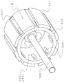
本発明の第1の態様は、図1から図4および図7に示されるように、通電可能な無鉄心の円筒コイル200と、円筒コイル200の一方の端面201が固定されて中心部310に駆動シャフト100が回転自在に連結されている蓋型マウント300とを有する固定子2と、蓋型マウント300に回転自在に連結されている駆動シャフト100が中心部410に連結固定されて蓋型マウント300の対極に配置されている、底部420と内側円筒空路形成体500および外側円筒空路形成体600とを有するカップ型マウント400と、外側円筒空路形成体600の内周面610および/または内側円筒空路形成体500の外周面520に円筒コイル200の円周方向に互いに隙間401を空けて配備されている複数のマグネット4とを有する回転子3と、
を含み、
カップ型マウント400は、底部420と内側円筒空路形成体500および外側円筒空路形成体600とで第1空隙のエアギャップ40が形成されており、エアギャップ40には、配備されている露出した複数のマグネット4と共に、円筒コイル200が該円筒コイル200の他方の端面202が底部420との間で隙間42を残して浮かせた状態で配置されており、カップ型マウント400の一方の端面530,630と蓋型マウント300との間に円筒コイル200の内周側210に位置する第2空隙20と円筒コイル200の外周側220に位置する第3空隙30とを有する無鉄心回転電気機械10であって、
カップ型マウント400は底部420に第2空隙20に外気70を引き込む通気孔430を有しており、回転子3の回転および複数のマグネット4の回転により発生する回転子周囲の圧力差によって第2空隙20に引き込まれた外気70は、第1空隙40を流通し、第1空隙40に露出した加熱している複数のマグネット4および第1空隙40に配置されている円筒コイル200の両面210,220を直接冷却し、第3空隙30を経由し、外部に排出されるようにした無鉄心回転電気機械10に関するものである。
As shown in FIGS. 1 to 4 and 7, the first aspect of the present invention is a coreless
Including
In the cup-
The cup-
本発明の第1の態様から明らかなように、無鉄心回転電気機械10は、カップ型マウント400の底部420に第2空隙20に外気70を引き込む通気孔430が設けられ、通気孔430を介し、回転子3の回転および複数のマグネット4の回転により発生する回転子周囲の圧力差によって第2空隙20に取り込まれた外気70は、第1空隙40に配置される円筒コイル200の内側および外側を通り、第3空隙30から排出されるように構成される。
As is clear from the first aspect of the present invention, the ironless rotary
本発明の一つの実施形態として、カップ型マウント400は、回転子3の回転および複数のマグネット4の回転により発生する回転子周囲の圧力差によって、内側円筒空路形成体500の内周側510に形成された第2空隙20に通じる空間540に外気70を取り入れるための複数の通気孔430および該通気孔430を覆うフィルター431を底部420に設けることができる。フィルター431は回転子3と一体に高速回転することによりごみをはじき飛ばすため、目詰まりしにくくなるという利点がある。
As one embodiment of the present invention, the cup-shaped
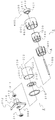
本発明のもう一つ実施形態として、図4に示されるように、複数のマグネット4の各々は、長辺は第1空隙40に配置されている円筒コイル200の長さLに対応し、短辺は円筒コイル200の円周方向に互いに隙間401を空けて、内側円筒空路形成体500の外周面520に円筒コイル200の長手方向に沿って配備されている直方体とすることができる。円筒コイル200の円周方向に互いに隙間401を空けて配備されている複数のマグネット4は、回転子3の回転と共に配備された複数のマグネット4の回転によって、第2空隙20に引き込まれる外気70の流量を増加させ、第1空隙40に流通する外気70による冷却効果をさらに高めることができる。
As another embodiment of the present invention, as shown in FIG. 4, each of the plurality of
本発明の一実施形態において、図2、図3および図4に示されるように、カップ型マウント400はさらに、円筒コイル200の長手方向に沿うように配備された複数のマグネット4の隙間401に相当する内側円筒空路形成体500の位置に内側排気孔560および/または外側円筒空路形成体600の位置に外側排気孔660を設けることができる。そうすることにより、第2空隙20に引き込まれる外気70の流量を増加させ、第1空隙40に流通する外気70による冷却効果をさらに高めることができる。
In one embodiment of the present invention, as shown in FIGS. 2, 3, and 4, the cup-
本発明のさらにもう一つの実施形態として、カップ型マウント400は、図6に示されるように、外側円筒空路形成体600の第3空隙30に対応する位置に2枚の円板2100と該円板2100の軸心に向い円板2100に懸架された複数の羽根板2200とを有する多翼遠心送風回転体が嵌装固定されている構成にすることができる。そうすることにより、外気70の流量をより増加させ、冷却効果を高めるようにすることができる。
As yet another embodiment of the present invention, as shown in FIG. 6, the cup-
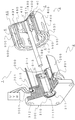
本発明の他の一つの実施形態として、固定子2は、蓋型マウント300に一方の端面901が支持された外側円筒空路形成体600より内径が大きい保護外套9を有する外装体をさらに含み、外装体9は第3空隙30から排出される外気70を外部に逃がす排出孔90を有する構成にすることができる。
As another embodiment of the present invention, the
本発明の第2の態様は、図1から図4および図7に示されるように、通電可能な無鉄心の円筒コイル200と、円筒コイル200の一方の端面201が固定されて中心部310に駆動シャフト100が回転自在に連結されている蓋型マウント300とを有する固定子2と、蓋型マウント300に回転自在に連結されている駆動シャフト100が中心部410に連結固定されて蓋型マウント300の対極に配置されている、底部420と内側円筒空路形成体500および外側円筒空路形成体600とを有するカップ型マウント400と、外側円筒空路形成体600の内周面610および/または内側円筒空路形成体500の外周面520に円筒コイル200の円周方向に互いに隙間401を空けて配備されている複数のマグネット4とを有する回転子3と、
を含み、
カップ型マウント400は、底部420と内側円筒空路形成体500および外側円筒空路形成体600とで第1空隙のエアギャップ40が形成されており、エアギャップ40には、配備されている露出した複数のマグネット4と共に、円筒コイル200が該円筒コイル200の他方の端面202が底部420との間で隙間42を残して浮かせた状態で配置されており、カップ型マウント400の一方の端面530,630と蓋型マウント300との間に円筒コイル200の内周側210に位置する第2空隙20と円筒コイル200の外周側220に位置する第3空隙30とを有しており、カップ型マウント400は底部420に第2空隙20に外気70を引き込む通気孔430を有する無鉄心回転電気機械10の冷却方法であって、
円筒コイル200に通電し、回転子3を作動させるステップと、回転子3の回転および複数のマグネット4の回転により発生する回転子3の周囲の圧力差によって、カップ型マウント400の通気孔430を介し、第2空隙20に外気70を引き込むステップと、第2空隙20に引き込まれた外気70は、回転子3の回転および複数のマグネット4の回転により発生する回転子3の周囲の圧力差によって、第1空隙40を流通し、第1空隙40に露出した加熱している複数のマグネット4および第1空隙40に配置されている円筒コイル200の両面210,220を直接冷却するステップと、回転子3の回転および複数のマグネット4の回転により発生する回転子3の周囲の圧力差によって第1空隙40を流通させた外気70を、第3空隙30を経由させ、無鉄心回転電気機械10から排出させるステップと、
を含む方法に関するものである。
As shown in FIGS. 1 to 4 and 7, the second aspect of the present invention is a coreless
Including
In the cup-
The
It is related with the method containing.
本発明の第2の態様から明らかなように、無鉄心回転電気機械10の冷却方法は、カップ型マウント400の底部420に設けられた第2空隙20に外気70を引き込むための通気孔430を介し、回転子3の回転および複数のマグネット4の回転により発生する回転子周囲の圧力差によって外気70を第2空隙20に取り込み、次に回転子3の回転および複数のマグネット4の回転により発生する回転子周囲の圧力差によって第2空隙20から外気70を、第1空隙40に流通させ、第1空隙40に露出した加熱している複数のマグネット4および第1空隙40に配置されている円筒コイル200の両面210,220を直接冷却させ、第3空隙30から排出させるものである。
As is apparent from the second aspect of the present invention, the cooling method for the iron-free rotating
本発明の一つの実施形態として、カップ型マウント400は、回転子3の回転および複数のマグネット4の回転により発生する回転子周囲の圧力差によって、内側円筒空路形成体500の内周側510に形成された第2空隙20に通じる空間540に外気70を取り入れるための複数の通気孔430および該通気孔430を覆うフィルター431を底部420に設けることができる。フィルター431は回転子3と一体に高速回転することによりごみをはじき飛ばすため、目詰まりしにくくなるという利点を有する。
As one embodiment of the present invention, the cup-shaped
本発明のもう一つ実施形態として、図4に示されるように、複数のマグネット4の各々は、長辺は第1空隙40に配置されている円筒コイル200の長さLに対応し、短辺は円筒コイル200の円周方向に互いに隙間401を空けて、外側円筒空路形成体600の内周面610および/または内側円筒空路形成体500の外周面520に円筒コイル200の長手方向に沿って配備されている直方体とすることができる。それにより、本方法は、回転子3の回転および配備された複数のマグネット4の回転により発生する回転子3周囲の圧力差をさらに高め、第2空隙20に引き込まれる外気70の流量を増加させ、第1空隙40に流通する外気70の冷却効果を高めることができるようにした方法である。
As another embodiment of the present invention, as shown in FIG. 4, each of the plurality of
本発明の一実施形態において、図2、図3および図4に示されるように、カップ型マウント400はさらに、円筒コイル200の長手方向に沿うように配備された複数のマグネット4の隙間401に相当する内側円筒空路形成体500の位置に内側排気孔560および/または外側円筒空路形成体600の位置に外側排気孔660を設けることができる。そうすることにより、第2空隙20に引き込まれる外気70の流量を増加させ、第1空隙40に流通する外気70による冷却効果をさらに高めることができるようにした方法である。
In one embodiment of the present invention, as shown in FIGS. 2, 3, and 4, the cup-
本発明のさらにもう一つの実施形態として、カップ型マウント300は、図6に示されるように、外側円筒空路形成体600の第3空隙30および/または外側排気孔660に対応する位置に2数の円板2100と該円板2100の軸心に向い円板2100に懸架された複数の羽根板2200とを有する多翼遠心送風回転体2000が外側円筒空路形成体600に嵌装固定されており、本方法は、多翼遠心送風回転体2000によって、回転子3の回転および複数のマグネット4の回転により発生する回転子3周囲の圧力差をさらに高め、第2空隙20に引き込まれた外気70の流量をさらに増加させ、外気70の冷却効果をより高め、それにより、外気70を、第1空隙40を流通させ、第3空隙30および外側排気孔660を経由させ、第1空隙40に露出した加熱している複数のマグネット4および第1空隙40に配置されている円筒コイル200の両面210,220を直接冷却し、無鉄心回転電気機械10から排出させるようにした方法である。
As yet another embodiment of the present invention, as shown in FIG. 6, the cup-
本発明の他のもう一つの実施形態として、図5に示されるように、固定子2は、蓋型マウント300に一方の端面201が支持された外側円筒空路形成体600より内径が大きい保護外套900を有する外装体9をさらに含み、外装体9は、外装体9の一部に排出孔90が設けられており、本方法は、それにより、第3空隙30および外側排気孔660から排出された外気70を排出孔90より逃がすステップをさらに含むことができる。
As another embodiment of the present invention, as shown in FIG. 5, the
回転電気機械の性能の一つである発生トルクT(N・m)は、電機子コイルに流れる電流の強さI(A)に比例し、出力P(W)はトルクT(N・m)と回転角速度ω(rad/s)の積で表される。一方電圧降下で見ると、電源電圧V(V)は電機子コイルに流れる電流I(A)と、電機子コイルの抵抗R(Ω)との積に誘導起電力である逆起電力E0(V)を合算した式とつりあう。
T=Kt×I・・・(1)
P=T×ω・・・(2)
V=IR+E0・・・(3)
上記の式より、トルクおよび出力を上げるためには、コイル抵抗値を下げることが重要であることがわかる。
The generated torque T (N · m), which is one of the performances of the rotating electrical machine, is proportional to the current intensity I (A) flowing through the armature coil, and the output P (W) is the torque T (N · m). And the rotational angular velocity ω (rad / s). On the other hand, in terms of the voltage drop, the power supply voltage V (V) is the product of the current I (A) flowing through the armature coil and the resistance R (Ω) of the armature coil, and the counter electromotive force E 0 ( It is balanced with the sum of V).
T = Kt × I (1)
P = T × ω (2)
V = IR + E 0 (3)
From the above equations, it can be seen that it is important to reduce the coil resistance value in order to increase the torque and output.
そこで本発明を特徴づける図1〜図4に示される円筒コイル200を含む固定子2を備えた無鉄心回転電気機械10(以下、「本発明の電動モータ10」と称する。)の基本構造について概観すると、基本構造の特徴は、第1に、固定電機子2を構成する通電可能なコイル体として、導電性金属シートの積層体構造によって成形された円筒コイル200を用いたことにある。それは、円筒コイル200およびその製造方法として、例えば特許文献7および特許文献8に記載されているように、長手方向に直交する離間された複数の線状部を有する導電性金属シートの複数で構成された積層体構造を有する円筒形であって導電性金属シートの各々の線状部が絶縁層で覆われている通電可能な無鉄心の円筒コイルであって、好ましくは、2層または4層からなる厚さが5mm以下の一定の剛性を有するものである。
Accordingly, the basic structure of a coreless rotary electric machine 10 (hereinafter referred to as “the
基本構造の特徴の第2には、それは、円筒コイル200の一方の端面201を、固定子2を構成する蓋型マウント300の内周面によって閉鎖し、円筒コイル200の開放された他方の端面202を、回転子3を構成する、例えば、カップ型マウント400の底部420と、複数のマグネット(永久磁石)4が配備された磁性体からなる外側円筒空路形成体600および内側円筒空路形成体500(これらの一実施形態として、以下外側円筒空路形成体を「アウターヨーク600」といい、内側円筒空路形成体を「インナーヨーク500」と称することとする。)と、によって断面ドーナツ状の磁界が形成される、第1空隙すなわちエアギャップ40に浮かせた状態で挿入配置する構造を有する。
The second feature of the basic structure is that one
さらに詳細には、エアギャップ40に挿入配置された円筒コイル200は、その内周面210および外周面220を回転子3のアウターヨーク600の内周面610およびインナーヨーク500の外周面520に接しないように、かつ、その開放端面202を、回転子3を構成するキャップ型マウント400の底部420に接しないように、エアギャップ40内に僅かの隙間42を空け浮かせた状態になる。それは、円筒コイル200がこのように配置されるように固定子2および回転子3を駆動シャフト100に配置する構造を有するものである。
More specifically, the
基本構造の特徴の第3には、それは、固定子2と円筒コイル200と回転子3とによって、第2空隙20および第3空隙30を形成する構造を有するものである。より詳細には、第2空隙20は、回転子3に一体化されたアウターヨークおよびインナーヨークの開放された端面と該端面に対置する固定子2の内面との間に、固定子2の内面によって閉鎖された円筒コイルの内周面210に形成され、その空隙540はエアギャップ40のみに通じる。また第3空隙30は、固定子2の内面によって閉鎖された円筒コイルの外周面220にエアギャップ40と外気との間に形成される。
A third feature of the basic structure is that the
そうなると、円筒コイル200の内周面210と固定子2の内面とで形成される閉鎖空間となる第2空隙20は、エアギャップ40のみに連通し、回転子3の内面を経て円筒コイル200の外周面220と固定子2の内面とアウターヨーク600の開放端とで形成される開放空間となる第3空隙30と連通させることができる。
Then, the
本発明の電動モータ10は、少なくとも第2空隙20が第3空隙30を経由してアウターヨーク600の開放端によって外気に通じる構造を有するものである。したがって、回転子3の回転により発生する回転子3の周囲の圧力差によって、第2空隙20は負圧状態が生成される。この負圧状態によって第2空隙20に外気70を取り入れ、ここに取り込まれた外気70は、磁界が形成されたエアギャップ40を通るときに円筒コイル200の内周面を経て外周面をなぞりながら、厚みが5mm以下の導電性金属シートの複数で構成された積層体構造の円筒コイル200の両面210,220を直接冷却し、第3空隙30を経由し、アウターヨーク600の開放端の第3空隙30から排出されることになる。
The
明らかなことは、本発明の電動モータ10は、回転子3の回転数が高まるほど、すなわち出力Wが大きくなればなるほど、回転子3の周囲の圧力差も大きくなるため、冷却効果も増すという画期的な技術的特徴を有する。それは、上記した本発明の電動モータ10の基本構造に由来するものである。すなわち、磁束密度が大きい狭隘のエアギャップ40に回転数が高まると増大する鉄損が存在しない無鉄心の円筒コイル200であって厚みが5mm以下の極薄厚の導電性金属シートの積層体構造に成形された剛性を有する円筒コイル200を浮かせた状態で挿入配置し、閉鎖空間540に通じる第2空隙20がアウターヨーク600の開放端30にのみ連通させた基本構造からなる電動モータという特徴に由来する。図7は、円筒コイル200を含む固定子2を備えた無鉄心回転電気機械10の一実施形態(プロトタイプ・モータ)である。
Obviously, the
図7に示される一実施形態の電動モータの断面図(a)および斜視図(b)について概説すると、第1に、厚みは1.35mmで外径は51mmの円筒コイル200は、幅11mmで長手方向の長さが37.75mmの第1空隙のエアギャップ40に挿入配置される。ところで複数のマグネット4は、図7の斜視図(b)に示されるように、厚さ3.85mmの直方体からなる8極のネオジム磁石を長手方向に1.19mmの間隔401を空けてインナーヨーク500の外周面520に配備される。なお間隔401を空けた複数のマグネット4の回転によるマグネット羽根機能については後述される。
Outline of the sectional view (a) and the perspective view (b) of the electric motor of one embodiment shown in FIG. 7 is as follows. First, the
第2に、回転子3に一体化されたアウターヨーク600およびインナーヨーク500の開放された端面と該端面に対置する固定子2の内面との間には、2.33mm幅の第2空隙20および第3空隙30が形成されており、閉鎖空間の第2空隙20には、冷却用空気を送り込むために外部と連通する内径3mmの経路3200を設けることができる。
Secondly, a
第3に、図7の断面図(a)に示されるように、円筒コイル200の内周面210とネオジム磁石の複数のマグネット4の外周面との間隙は僅か0.3mmであり、円筒コイル200の外周面220とアウターヨーク600の内周面610との間隙は、0.4mmに過ぎない。いずれの間隙も狭隘である。
Third, as shown in the sectional view (a) of FIG. 7, the gap between the inner peripheral surface 210 of the
ところで、電動機は電力を動力に変換する装置、つまり電気的エネルギーを機械的エネルギーに変換するためのものである。一方、発電機は動力を電力に変換するものであり、両者に構造的な違いは無いため、本発明は電動機および発電機が対象となる。エネルギー変換するプロセスにおいて、各種の損失が発生し熱に変わってしまう。一般的な回転電気機械の損失は、(i)銅損、(ii)鉄損(ヒステリシス損失+渦電流損失)、(iii)機械損に分類される。この中で(i)銅損、(ii)鉄損が損失に占める割合が大きい。厚みが5mm以下の導電性金属シートの複数で構成された積層体構造の円筒コイル200を含む固定子2および円筒コイル200を浮かせた状態で挿入配置するエアギャップ40を含む回転子3によって構成された本発明の電動モータにおいては、無鉄心であるため(ii)鉄損が生じることはないが、円筒コイル200に渦電流損が発生し、これも(i)銅損とともに円筒コイル200の発熱要因となる。したがって、本発明の技術的課題の第1は、円筒コイル200の発熱を制御することであり、技術的課題の第2は、エアギャップ40の長手方向にインナーヨーク500の外周面520に配備される直方体の複数のマグネット4が加熱により保磁力を劣化させないように、複数のマグネット4の加熱を抑制することである。
By the way, the electric motor is a device for converting electric power into motive power, that is, for converting electric energy into mechanical energy. On the other hand, since the generator converts power into electric power and there is no structural difference between the two, the present invention is directed to the electric motor and the generator. In the process of energy conversion, various losses occur and turn into heat. The loss of a general rotating electrical machine is classified into (i) copper loss, (ii) iron loss (hysteresis loss + eddy current loss), and (iii) mechanical loss. Among these, (i) copper loss and (ii) iron loss account for a large proportion of the loss. The
また複数のマグネットの加熱による保磁力の劣化について付言すると、電動モータの多くの用途で小型化が求められているものの、同じ素材のマグネットで磁束密度を高めることは難しい。ところが従来型のフェライト磁石を希土類磁石、例えばネオジム磁石に変更するだけで、同じ大きさの電動モータのトルクを高めることができる(非特許文献1の53ページを参照されたい。)。また希土類のネオジムと鉄とホウ素を主成分とするネオジム磁石についてさらに付言すると、それは、非常に磁力は強いけれども熱による減磁作用が大きく、80℃程度が使用限度であるという(非特許文献1の27ページを参照されたい。)。なお、本発明の電動モータに用いるマグネット4は、耐熱タイプのネオジム磁石であることがより好ましい。
In addition, regarding the deterioration of coercive force due to heating of a plurality of magnets, although miniaturization is required for many uses of electric motors, it is difficult to increase the magnetic flux density with magnets of the same material. However, the torque of an electric motor of the same magnitude can be increased only by changing a conventional ferrite magnet to a rare earth magnet, such as a neodymium magnet (see
電力モータの性能を見る尺度の一つは、モータの駆動電圧を高く設定すれば、当然、回転数(rpm)は増大する。それにともなって、出力(W)も高くなる。出力(W)が高くなればなるほど、円筒コイル200の発熱量(J/m3)も増大する。そのことにより、円筒コイル200の抵抗値Rは必然的に高まる。また、出力(W)の大きさによって評価することが出来る。電力モータの性能を見る上記とは別の尺度として、入力電力に対する出力動力の比(Po/Pi)すなわち効率ηによって評価することができる。
One of the measures for measuring the performance of an electric motor is that if the motor drive voltage is set high, the rotational speed (rpm) naturally increases. Along with this, the output (W) also increases. The higher the output (W), the greater the amount of heat generated by the cylindrical coil 200 (J / m 3 ). As a result, the resistance value R of the
上記した技術的課題に対しては、例えば、特許文献5および6に記載されている電動モータの内部に外気を取り入れ、マグネットの表面を冷却し何層にも巻線されたコイル表面を冷却する試み等がなされているが、抜本的な課題解決には至っていない。本発明は、こうした技術的課題に挑戦し開発された電動モータである。
For the above technical problem, for example, outside air is introduced into the electric motor described in
本発明において重要なことは、図1に示されたように、回転子3を構成するカップ型マウント400の底部420に複数の通気口430を設けて回転子3の回転により発生する回転子3の周囲の圧力差によって、外気70を取り入れるようにしたことである。電動モータ内に外気を取り入れて電動モータのコイルやマグネットの冷却することは周知である。しかしながら、本発明の電動モータの基本構造である図4に示された外側円筒空路形成体600の内周面610および/または内側円筒空路形成体500の外周面520に円筒コイル200の円周方向に互いに隙間401を空けて配備されている複数のマグネット4に着目し、以下のようなマグネットの羽根効果が生じることを明らかにした。
What is important in the present invention is that the
図7(b)の模式図に示されているインナーヨーク500の表面に駆動シャフト100の長手方向に沿って接着固定された直方体の複数のマグネット4は、インナーヨーク500の表面の形状に合わせエボキシ系の接着剤等を用い、ポリアミド樹脂等で固めた8極のマグネット4に相当する。1.19mmの間隔は、各々のマグネット4の間隔401に相当する。第2空隙に引き込まれた外気70は、回転子3の回転に加えて複数のマグネット4の回転により発生する回転子3の周囲の圧力差によって、第1空隙40を流通し、第1空隙に露出した加熱している複数のマグネット4および第1空隙40に配置されている円筒コイル200の両面を直接冷却し、第3空隙30を経由して本発明の電動モータ10の外部に排出される。
A plurality of
図6は、図1および図4に示された無鉄心回転電気機械10のインナーヨーク500およびアウターヨーク600に設けられた複数のマグネット4の各々の間隔401に対応する位置に、円筒コイル200およびインナーヨーク500およびアウターヨーク600に配備されている複数のマグネット4の各々に対する冷却効果を高めるための多翼遠心送風回転体2000が回転子3を構成するカップ型マウント400に嵌装固定されるようにしたものである。
6 shows a
そのカップ型マウント400は、第3空隙30および/または外側排気孔660に対応する位置に2枚の円板2100と円板2100の軸心に向い2枚の円板2100に懸架された複数の羽根板2200で構成された水車型のアウターヨーク600に嵌装固定される多翼遠心送風回転体2000を有し、それにより、第3空隙30および/または外側排気孔660から外気70を排出させる回転子3の回転および複数のマグネットの回転により発生する回転子3の周囲の圧力差を増幅させることができる。すなわち、吸引される外気70の流量を増やし、外気70を第1空隙40内の流通を高速化して冷却効果を高めることができる。
The cup-
本電動モータ内部に外気70を引き込むことができる閉鎖空間540に通じる第2空隙20が形成され、そこから、円筒コイル200の内周面210および外周面220をなぞりながら、第3空隙30および/または外側排気孔660から熱せられた外気70を外部に排出できるようにした。これは、駆動電圧を高く設定するほど、冷却効果が大きいという実現不能と思われていた技術的課題を解決させた。
A
本発明は、好ましい実施形態に関連して記載されたが、当業者であれば、本発明の範囲から逸脱することなく、様々な変更がなされ、均等物がそれについての要素に代替され得ることが理解されるであろう。したがって、本発明を実施するために考慮された最良の実施態様として開示された特定の実施態様に限定されるものではなく、特許請求の範囲に属する全ての実施形態を含むものであることがいとされる。
Although the present invention has been described with reference to preferred embodiments, those skilled in the art will recognize that various modifications can be made and equivalents can be substituted for elements thereof without departing from the scope of the invention. Will be understood. Accordingly, it is not intended to be limited to the specific embodiments disclosed as the best mode contemplated for carrying out the invention, but to include all embodiments that fall within the scope of the claims. .
1 電機子を含む無鉄心回転電気機械の構造
2 固定子
3 回転子
4 マグネット
9 外装体
10 電機子を含む無鉄心回転電気機械
20 第2空隙
30 第3空隙
40 第1空隙またはエアギャップ
41 内側間隙
42 中間間隙
43 外側間隙
70 第2空隙に引き込まれた外気
90 排出孔
100 駆動シャフト
110 駆動シャフトの中間部
120 駆動シャフトの終端部
200 円筒コイル
201 円筒コイルの(固定)端面
202 円筒コイルの(開放)端面
210 円筒コイルの内周面
220 円筒コイルの外周面
300 蓋型マウント
310 蓋型マウントの中心部
400 カップ型マウント
401 隣接するマグネットの間の隙間
410 カップ型マウントの中心部
420 カップ型マウントの底部
430 通気孔
431 通気孔用フィルター
500 内側円筒空路形成体またはインナーヨーク
510 内側円筒空路形成体またはインナーヨークの内周側
520 内側円筒空路形成体またはインナーヨークの外周面
530 内側円筒空路形成体またはインナーヨークの端面
540 内側円筒空路形成体またはインナーヨークの内周側空間
600 外側円筒空路形成体またはアウターヨーク
610 外側円筒空路形成体またはアウターヨークの内周面
620 外側円筒空路形成体またはアウターヨークの外周面
630 外側円筒空路形成体またはアウターヨークの端面
900 保護外套
901 保護外套の端面
2000 多翼遠心送風回転体
2100 多翼遠心送風回転体の円板
2200 多翼遠心送風回転体の羽根板
DESCRIPTION OF
DESCRIPTION OF
100 Drive shaft 110 Middle portion of drive shaft 120 End portion of drive shaft
200 Cylindrical coil 201 (fixed)
300
400 Cup-
500 Inner cylindrical air passage formation body or inner yoke 510 Inner cylindrical air passage formation body or inner yoke inner side 520 Inner cylindrical air passage formation body or inner yoke outer surface 530 Inner cylindrical air passage formation body or inner
600 Outer cylindrical air passage former or outer yoke 610 Outer cylindrical air passage former or outer yoke inner peripheral surface 620 Outer cylindrical air passage former or outer yoke outer
900
2000 Multiblade
Claims (14)
前記蓋型マウントに回転自在に連結されている前記駆動シャフトが中心部に連結固定されて前記蓋型マウントの対極に配置されている、底部と内側円筒空路形成体および外側円筒空路形成体とを有するカップ型マウントと、前記外側円筒空路形成体の内周面および/または前記内側円筒空路形成体の外周面に前記円筒コイルの円周方向に互いに間隙を空けて配備されている複数のマグネットとを有する回転子と、
を含み、
前記カップ型マウントは、前記底部と前記内側円筒空路形成体および前記外側円筒空路形成体とで第1空隙のエアギャップが形成されており、前記エアギャップには、配備されている露出した前記複数のマグネットと共に、前記円筒コイルが該円筒コイルの他方の端面が前記底部との間で隙間を残して浮かせた状態で配置されており、前記カップ型マウントの一方の端面と前記蓋型マウントとの間に前記円筒コイルの内周側に位置する第2空隙と前記円筒コイルの外周側に位置する第3空隙とを有する無鉄心回転電気機械であって、
前記カップ型マウントは前記底部に前記第2空隙に外気を引き込む通気孔を有しており、前記回転子の回転および前記複数のマグネットの回転により発生する前記回転子周囲の圧力差によって前記第2空隙に引き込まれた前記外気は、前記第1空隙を流通し、前記第1空隙に露出した加熱している前記複数のマグネットおよび前記第1空隙に配置されている前記円筒コイルの両面を直接冷却し、前記第3空隙を経由して外部に排出されるようにしたことを特徴とする無鉄心回転電気機械。 A stator having an iron-free cylindrical coil that can be energized, and a lid-type mount in which one end face of the cylindrical coil is fixed and a drive shaft is rotatably connected to a central portion;
The drive shaft, which is rotatably connected to the lid-type mount, is connected and fixed to the center portion, and is disposed at the counter electrode of the lid-type mount, and includes a bottom portion, an inner cylindrical air passage formation body, and an outer cylindrical air passage formation body. And a plurality of magnets disposed on the inner peripheral surface of the outer cylindrical air passage formation body and / or the outer peripheral surface of the inner cylindrical air passage formation body with a gap therebetween in the circumferential direction of the cylindrical coil. A rotor having
Including
In the cup-type mount, an air gap of a first gap is formed by the bottom portion, the inner cylindrical air passage formation body, and the outer cylindrical air passage formation body, and the plurality of exposed exposed plurality of air gaps are provided in the air gap. The cylindrical coil is disposed in a state where the other end surface of the cylindrical coil is left floating with a gap between the magnet and the one of the cup-type mount and the lid-type mount. An ironless rotary electric machine having a second gap located on the inner circumference side of the cylindrical coil and a third gap located on the outer circumference side of the cylindrical coil,
The cup-type mount has a vent hole at the bottom for drawing outside air into the second gap, and the second mount is formed by a pressure difference around the rotor generated by rotation of the rotor and rotation of the plurality of magnets. The outside air drawn into the gap flows through the first gap, and directly cools both surfaces of the heated magnets exposed to the first gap and the cylindrical coil arranged in the first gap. And a non-core rotating electric machine characterized by being discharged to the outside via the third gap.
前記蓋型マウントに回転自在に連結されている前記駆動シャフトが中心部に連結固定されて前記蓋型マウントの対極に配置されている、底部と内側円筒空路形成体および外側円筒空路形成体とを有するカップ型マウントと、前記外側円筒空路形成体の内周面および/または前記内側円筒空路形成体の外周面に前記円筒コイルの円周方向に互いに間隙を空けて配備されている複数のマグネットとを有する回転子と、
を含み、
前記カップ型マウントは、前記底部と前記内側円筒空路形成体および前記外側円筒空路形成体とで第1空隙のエアギャップが形成されており、前記エアギャップには、配備されている露出した前記複数のマグネットと共に、前記円筒コイルが該円筒コイルの他方の端面が前記底部との間で隙間を残して浮かせた状態で配置されており、前記カップ型マウントの一方の端面と前記蓋型マウントとの間には、前記円筒コイルの内周側に位置する第2空隙と前記円筒コイルの外周側に位置する第3空隙とを有しており、前記カップ型マウントは前記底部に前記第2空隙に外気を引き込む通気孔を有する無鉄心回転電気機械の冷却方法であって、
前記円筒コイルに通電し、前記回転子を作動させるステップと、
前記回転子の回転および前記複数のマグネットの回転により発生する前記回転子周囲の圧力差によって、前記通気孔を介して前記第2空隙に前記外気を引き込むステップと、
前記第2空隙に引き込まれた前記外気は、前記回転子の回転および前記複数のマグネットの回転により発生する前記回転子周囲の圧力差によって、前記第1空隙を流通して前記第1空隙に露出した加熱している前記複数のマグネットおよび前記第1空隙に配置されている前記円筒コイルを直接冷却するステップと、
前記回転子の回転および前記複数のマグネットの回転により発生する前記回転子周囲の圧力差によって前記第1空隙を流通させた前記外気を、前記第3空隙を経由させ、前記無鉄心回転電気機械から排出させるステップと、
を含むことを特徴とする方法。 A stator having an iron-free cylindrical coil that can be energized, and a lid-type mount in which one end face of the cylindrical coil is fixed and a drive shaft is rotatably connected to a central portion;
The drive shaft, which is rotatably connected to the lid-type mount, is connected and fixed to the center portion, and is disposed at the counter electrode of the lid-type mount, and includes a bottom portion, an inner cylindrical air passage formation body, and an outer cylindrical air passage formation body. And a plurality of magnets disposed on the inner peripheral surface of the outer cylindrical air passage formation body and / or the outer peripheral surface of the inner cylindrical air passage formation body with a gap therebetween in the circumferential direction of the cylindrical coil. A rotor having
Including
In the cup-type mount, an air gap of a first gap is formed by the bottom portion, the inner cylindrical air passage formation body, and the outer cylindrical air passage formation body, and the plurality of exposed exposed plurality of air gaps are provided in the air gap. The cylindrical coil is disposed in a state where the other end surface of the cylindrical coil is left floating with a gap between the magnet and the one of the cup-type mount and the lid-type mount. There is a second gap located on the inner circumference side of the cylindrical coil and a third gap located on the outer circumference side of the cylindrical coil, and the cup-type mount is located on the bottom portion in the second gap. A cooling method for a coreless rotating electrical machine having a vent hole for drawing outside air,
Energizing the cylindrical coil to actuate the rotor;
Drawing the outside air into the second gap through the vent hole by a pressure difference around the rotor generated by rotation of the rotor and rotation of the plurality of magnets;
The outside air drawn into the second gap flows through the first gap and is exposed to the first gap due to a pressure difference around the rotor generated by rotation of the rotor and rotation of the plurality of magnets. Directly cooling the heated magnets and the cylindrical coil disposed in the first gap;
The outside air that has circulated through the first air gap due to the pressure difference around the rotor generated by the rotation of the rotor and the rotation of the plurality of magnets passes through the third air gap, from the ironless rotary electric machine. Draining step;
A method comprising the steps of:
Applications Claiming Priority (2)
| Application Number | Priority Date | Filing Date | Title |
|---|---|---|---|
| JP2014180294 | 2014-09-04 | ||
| JP2014180294 | 2014-09-04 |
Related Parent Applications (1)
| Application Number | Title | Priority Date | Filing Date |
|---|---|---|---|
| JP2015551643A Division JP5943333B1 (en) | 2014-09-04 | 2015-03-04 | Iron-free rotating electric machine including a stator having a cylindrical coil and its cooling method |
Publications (3)
| Publication Number | Publication Date |
|---|---|
| JP2016154440A JP2016154440A (en) | 2016-08-25 |
| JP2016154440A5 true JP2016154440A5 (en) | 2017-05-25 |
| JP6198085B2 JP6198085B2 (en) | 2017-09-20 |
Family
ID=55439433
Family Applications (2)
| Application Number | Title | Priority Date | Filing Date |
|---|---|---|---|
| JP2015551643A Active JP5943333B1 (en) | 2014-09-04 | 2015-03-04 | Iron-free rotating electric machine including a stator having a cylindrical coil and its cooling method |
| JP2016061769A Active JP6198085B2 (en) | 2014-09-04 | 2016-03-25 | Iron-free rotating electric machine including a stator having a cylindrical coil and its cooling method |
Family Applications Before (1)
| Application Number | Title | Priority Date | Filing Date |
|---|---|---|---|
| JP2015551643A Active JP5943333B1 (en) | 2014-09-04 | 2015-03-04 | Iron-free rotating electric machine including a stator having a cylindrical coil and its cooling method |
Country Status (6)
| Country | Link |
|---|---|
| US (2) | US10651702B2 (en) |
| JP (2) | JP5943333B1 (en) |
| KR (1) | KR101996320B1 (en) |
| CN (1) | CN106716793B (en) |
| DE (1) | DE112015004041T5 (en) |
| WO (1) | WO2016035358A1 (en) |
Families Citing this family (33)
| Publication number | Priority date | Publication date | Assignee | Title |
|---|---|---|---|---|
| KR101996320B1 (en) * | 2014-09-04 | 2019-07-04 | 가부시키가이샤 앰링크 | Coreless rotating electric machine provided with stator including cylindrical coil and cooling method for same |
| JP6005886B1 (en) * | 2016-03-03 | 2016-10-12 | 株式会社エムリンク | Iron-free rotating electric machine including a stator having a cylindrical coil and its cooling method |
| US20180048195A1 (en) * | 2016-08-10 | 2018-02-15 | Chin-Hsing Feng | Electric motor |
| DE112016007469T5 (en) * | 2016-11-24 | 2019-08-14 | M-Link Co., Ltd. | Coreless rotating electrical machine for operation with overload, drive method for this and this containing drive system |
| JP6925825B2 (en) * | 2017-03-01 | 2021-08-25 | ミネベアミツミ株式会社 | motor |
| JP6579522B2 (en) * | 2017-03-27 | 2019-09-25 | 株式会社エムリンク | Brushless rotating electrical machine including a stator having a coreless cylindrical coil and a brushless rotating electrical machine including a stator having a coreless cylindrical coil mounted with the cooling assisting tool |
| CN106877539B (en) * | 2017-04-16 | 2018-10-26 | 朱幕松 | Iron-core-free brushless gearless big hub motor |
| FR3066968B1 (en) * | 2017-06-02 | 2021-01-01 | Valeo Systemes Dessuyage | MOTOR-REDUCER FOR AUTOMOTIVE VEHICLE WIPING SYSTEM |
| JP6501026B1 (en) * | 2017-07-21 | 2019-04-17 | 株式会社デンソー | Electric rotating machine |
| WO2019017496A1 (en) * | 2017-07-21 | 2019-01-24 | 株式会社デンソー | Rotating electrical machine |
| US11843334B2 (en) | 2017-07-13 | 2023-12-12 | Denso Corporation | Rotating electrical machine |
| JP6885328B2 (en) | 2017-07-21 | 2021-06-16 | 株式会社デンソー | Rotating machine |
| CN113972807B (en) * | 2017-07-21 | 2023-10-27 | 株式会社电装 | Rotary electric machine |
| JP6501427B2 (en) * | 2017-11-14 | 2019-04-17 | 株式会社エムリンク | Ironless core rotary electric machine for operating with load exceeding rating, method of driving the same, and driving system including the same |
| JP6927186B2 (en) | 2017-12-28 | 2021-08-25 | 株式会社デンソー | Rotating machine |
| DE112018006651T5 (en) | 2017-12-28 | 2020-10-08 | Denso Corporation | Wheel drive device |
| JP7006541B2 (en) * | 2017-12-28 | 2022-01-24 | 株式会社デンソー | Rotating machine |
| DE112018006717T5 (en) | 2017-12-28 | 2020-09-10 | Denso Corporation | Rotating electric machine |
| DE112018006699T5 (en) | 2017-12-28 | 2020-09-10 | Denso Corporation | Rotating electric machine |
| WO2019131911A1 (en) * | 2017-12-28 | 2019-07-04 | 株式会社デンソー | Rotating electrical machine |
| EP3518385B1 (en) | 2018-01-12 | 2023-03-01 | Carrier Corporation | Coreless electromagnetic machine with dual rotor |
| WO2020022366A1 (en) * | 2018-07-25 | 2020-01-30 | 株式会社デンソー | Dynamo-electric machine and wheel using said dynamo-electric machine |
| JP7255383B2 (en) * | 2018-07-25 | 2023-04-11 | 株式会社デンソー | Rotating electric machine |
| JP7172589B2 (en) * | 2018-12-27 | 2022-11-16 | 株式会社デンソー | Rotating electric machine |
| DE102019200098A1 (en) | 2019-01-07 | 2020-07-09 | Audi Ag | Fluid-cooled rotor for an electrical machine |
| US11128197B2 (en) * | 2019-09-20 | 2021-09-21 | Hts Llc | Linear electric device having reciprocating movement linked to rotational movement of a shaped cam |
| DE102019126980B4 (en) | 2019-10-08 | 2022-10-20 | Hirschvogel Umformtechnik Gmbh | electrical machine |
| CN110649731A (en) * | 2019-10-26 | 2020-01-03 | 山东华盛农业药械有限责任公司 | Column type coreless motor |
| US11437900B2 (en) | 2019-12-19 | 2022-09-06 | Black & Decker Inc. | Modular outer-rotor brushless motor for a power tool |
| US11757330B2 (en) | 2019-12-19 | 2023-09-12 | Black & Decker, Inc. | Canned outer-rotor brushless motor for a power tool |
| EP3993228A1 (en) * | 2020-10-27 | 2022-05-04 | BSH Hausgeräte GmbH | Rotor core, permanent magnet rotor, electric motor and electric pump for a household appliance |
| DE102022209762A1 (en) | 2022-09-16 | 2024-03-21 | Rolls-Royce Deutschland Ltd & Co Kg | Electric machine with open coil winding for direct cooling |
| CN116505686B (en) * | 2023-06-26 | 2023-09-26 | 中山格智美电器有限公司 | Rotor structure for improving heat dissipation performance of outer rotor brushless motor and motor |
Family Cites Families (28)
| Publication number | Priority date | Publication date | Assignee | Title |
|---|---|---|---|---|
| JPS494056A (en) | 1972-05-03 | 1974-01-14 | ||
| US4562367A (en) * | 1982-06-30 | 1985-12-31 | Mitsubishi Denki Kabushiki Kaisha | Low inertia, speed variable induction motor |
| MX161230A (en) | 1985-12-23 | 1990-08-24 | Unique Mobility Inc | IMPROVEMENTS IN LIGHTWEIGHT ELECTROMAGNETIC TRANSDUCER |
| US5319844A (en) | 1985-12-23 | 1994-06-14 | Unique Mobility, Inc. | Method of making an electromagnetic transducer |
| JPS62268335A (en) | 1986-05-14 | 1987-11-20 | Toshiba Corp | Rotary electric machine for rolling stock |
| JPH0522133A (en) | 1991-07-17 | 1993-01-29 | Hitachi Ltd | A/d converter and analog/digital mixing ic |
| JP2517970Y2 (en) | 1991-09-06 | 1996-11-20 | 株式会社四国総合研究所 | Cooling structure of electric motor for electric vehicle |
| JP2571289Y2 (en) | 1992-03-31 | 1998-05-18 | 神鋼電機株式会社 | Cooling structure of outer rotor type high speed rotating electric machine |
| JPH05344680A (en) * | 1992-06-05 | 1993-12-24 | Toshiba Toransupooto Eng Kk | Outer rotor motor for vehicle |
| JP2571302Y2 (en) * | 1992-07-20 | 1998-05-18 | 株式会社安川電機 | Cooling device for high-speed rotating electrical machines |
| JP2657192B2 (en) | 1992-11-17 | 1997-09-24 | セイコープレシジョン株式会社 | Linear DC brushless motor |
| DE4414527C1 (en) * | 1994-04-26 | 1995-08-31 | Orto Holding Ag | Electronically-commutated DC motor for vehicle propulsion drive |
| JPH09168246A (en) * | 1995-12-13 | 1997-06-24 | Fuji Electric Co Ltd | Cooling device of permanent magnet synchronous machine |
| JP3494056B2 (en) | 1999-01-25 | 2004-02-03 | 国産電機株式会社 | Outer rotor type magnet generator |
| US6111329A (en) | 1999-03-29 | 2000-08-29 | Graham; Gregory S. | Armature for an electromotive device |
| US6873085B2 (en) | 2001-05-16 | 2005-03-29 | G & G Technology, Inc. | Brushless motor |
| JP4728639B2 (en) * | 2004-12-27 | 2011-07-20 | 株式会社デンソー | Electric wheel |
| JP2006246678A (en) | 2005-03-07 | 2006-09-14 | Toyota Motor Corp | Outer-rotor in-wheel type motor, electric automobile, and hybrid vehicle |
| KR100677281B1 (en) * | 2005-06-16 | 2007-02-02 | 엘지전자 주식회사 | Hybride induction motor applied toroidal winding methode |
| JP2010166717A (en) | 2009-01-16 | 2010-07-29 | Nissan Motor Co Ltd | Cooling structure for multilayered motor |
| JP5798815B2 (en) | 2010-07-02 | 2015-10-21 | 株式会社エムリンク | Wheel-in motor and electric vehicle |
| US9150093B2 (en) * | 2010-07-02 | 2015-10-06 | M-Link Co., Ltd. | In-wheel motor and electrically driven vehicle |
| JP5562741B2 (en) | 2010-07-02 | 2014-07-30 | 株式会社エムリンク | Wheel-in motor and electric vehicle |
| CN202167957U (en) * | 2011-03-25 | 2012-03-14 | 安鲁荣 | Low rotate speed and multi-rotor generator |
| JP5702748B2 (en) * | 2012-03-07 | 2015-04-15 | 本田技研工業株式会社 | Electric vehicle high voltage equipment cooling system and electric vehicle high voltage equipment cooling method |
| CN102946181A (en) * | 2012-11-26 | 2013-02-27 | 王九龙 | Novel motor |
| KR101996320B1 (en) * | 2014-09-04 | 2019-07-04 | 가부시키가이샤 앰링크 | Coreless rotating electric machine provided with stator including cylindrical coil and cooling method for same |
| JP6005886B1 (en) * | 2016-03-03 | 2016-10-12 | 株式会社エムリンク | Iron-free rotating electric machine including a stator having a cylindrical coil and its cooling method |
-
2015
- 2015-03-04 KR KR1020177007599A patent/KR101996320B1/en active IP Right Grant
- 2015-03-04 CN CN201580047697.0A patent/CN106716793B/en active Active
- 2015-03-04 US US15/508,633 patent/US10651702B2/en active Active
- 2015-03-04 DE DE112015004041.2T patent/DE112015004041T5/en not_active Withdrawn
- 2015-03-04 WO PCT/JP2015/056310 patent/WO2016035358A1/en active Application Filing
- 2015-03-04 JP JP2015551643A patent/JP5943333B1/en active Active
-
2016
- 2016-03-25 JP JP2016061769A patent/JP6198085B2/en active Active
-
2018
- 2018-07-10 US US16/031,247 patent/US10637319B2/en active Active
Similar Documents
| Publication | Publication Date | Title |
|---|---|---|
| JP6198085B2 (en) | Iron-free rotating electric machine including a stator having a cylindrical coil and its cooling method | |
| JP2016154440A5 (en) | ||
| JP6005886B1 (en) | Iron-free rotating electric machine including a stator having a cylindrical coil and its cooling method | |
| JP4999990B2 (en) | Rotating motor and blower using the same | |
| US10630157B2 (en) | Axial flux machine | |
| TWI420786B (en) | Electric machine having segmented stator | |
| KR102117140B1 (en) | Pole Shoe Cooling Gap for Axial Motor | |
| US8760016B2 (en) | Electric machine with enhanced cooling | |
| JP2012175755A (en) | Permanent magnet rotary electric machine | |
| JP6469964B2 (en) | Permanent magnet rotating electric machine | |
| JP2009142024A (en) | Reluctance motor | |
| JP6579522B2 (en) | Brushless rotating electrical machine including a stator having a coreless cylindrical coil and a brushless rotating electrical machine including a stator having a coreless cylindrical coil mounted with the cooling assisting tool | |
| JP2010166703A (en) | Permanent magnet rotating electrical machine | |
| JP6602619B2 (en) | Rotating electric machine or wind power generation system | |
| WO2023112829A1 (en) | Single-phase rotary electric machine, and vacuum cleaner, electric aircraft, and electric machine to which single-phase rotary electric machine is applied | |
| KR101903169B1 (en) | Hollow type BLDC Motor | |
| JP2023072105A (en) | rotor and motor | |
| JP5404525B2 (en) | Rotating electric machine | |
| JP2010136460A (en) | Rotating electric machine | |
| TWI325470B (en) |