JP6579522B2 - Brushless rotating electrical machine including a stator having a coreless cylindrical coil and a brushless rotating electrical machine including a stator having a coreless cylindrical coil mounted with the cooling assisting tool - Google Patents
Brushless rotating electrical machine including a stator having a coreless cylindrical coil and a brushless rotating electrical machine including a stator having a coreless cylindrical coil mounted with the cooling assisting tool Download PDFInfo
- Publication number
- JP6579522B2 JP6579522B2 JP2017060960A JP2017060960A JP6579522B2 JP 6579522 B2 JP6579522 B2 JP 6579522B2 JP 2017060960 A JP2017060960 A JP 2017060960A JP 2017060960 A JP2017060960 A JP 2017060960A JP 6579522 B2 JP6579522 B2 JP 6579522B2
- Authority
- JP
- Japan
- Prior art keywords
- cylindrical
- gap
- rotor
- stator
- cylindrical coil
- Prior art date
- Legal status (The legal status is an assumption and is not a legal conclusion. Google has not performed a legal analysis and makes no representation as to the accuracy of the status listed.)
- Active
Links
Images


Classifications
-
- H—ELECTRICITY
- H02—GENERATION; CONVERSION OR DISTRIBUTION OF ELECTRIC POWER
- H02K—DYNAMO-ELECTRIC MACHINES
- H02K5/00—Casings; Enclosures; Supports
- H02K5/04—Casings or enclosures characterised by the shape, form or construction thereof
- H02K5/20—Casings or enclosures characterised by the shape, form or construction thereof with channels or ducts for flow of cooling medium
-
- H—ELECTRICITY
- H02—GENERATION; CONVERSION OR DISTRIBUTION OF ELECTRIC POWER
- H02K—DYNAMO-ELECTRIC MACHINES
- H02K9/00—Arrangements for cooling or ventilating
- H02K9/02—Arrangements for cooling or ventilating by ambient air flowing through the machine
Description
本発明は、無鉄心の円筒コイルを備えた固定子を含むブラシレス回転電気機械の冷却補助具および冷却補助具が装備された無鉄心の円筒コイルを備えた固定子を含むブラシレス回転電気機械に関する。より具体的には、本発明は、底部と内側円筒空路形成体および外側円筒空路形成体と複数のマグネットとを有する回転子と、回転子に対向するように配備される無鉄心の円筒コイルが固定された固定子とからなるブラシレス回転電気機械の冷却補助具、あるいは、冷却補助具が装着された無鉄心の円筒コイルを備えた固定子を含むブラシレス回転電気機械に関する。 The present invention relates to a cooling aid for a brushless rotary electric machine including a stator having a coreless cylindrical coil and a brushless rotary electric machine including a stator having a coreless cylindrical coil equipped with the cooling auxiliary. More specifically, the present invention relates to a rotor having a bottom portion, an inner cylindrical air passage formation body, an outer cylindrical air passage formation body, and a plurality of magnets, and a coreless cylindrical coil arranged to face the rotor. The present invention relates to a cooling aid for a brushless rotating electrical machine comprising a fixed stator, or a brushless rotating electrical machine including a stator having a coreless cylindrical coil on which the cooling aid is mounted.
電動モータと発電機は同じ構造を有する回転電気機械である。回転電気機械について、電気エネルギーを機械エネルギーに変換する電動モータを用いて説明する。電動モータは、磁界と電流の相互作用で発生する電磁力を出力させるものである。分類方法はさまざまであるが、大きくはブラシ付きのDCモータとブラシレスモータに区分され、前者は磁石を固定子(ステータ)に、コイルを回転子(ロータ)とし、後者は逆にコイルを固定子(ステータ)に、磁石を回転子(ロータ)としており、いずれも回転子より外部へ電磁力を出力するものである。一方磁界発生方法の違いにより巻線界磁型と永久磁石界磁型にも区分され、コイルに鉄心(コア)が有るものとないもの(コアレス)にも区分される。上記区分からすると、永久磁石界磁型の無鉄心(コアレス)の円筒コイルを含むブラシレスモータが本発明の対象になる。
したがって、本発明の「無鉄心の円筒コイルを備えた固定子を含むブラシレス回転電気機械」は、以下において、「コアレス・ブラシレスモータ」として説明される。
The electric motor and the generator are rotating electric machines having the same structure. A rotating electric machine will be described using an electric motor that converts electric energy into mechanical energy. An electric motor outputs an electromagnetic force generated by the interaction between a magnetic field and a current. There are various classification methods, but it is roughly divided into DC motors with brushes and brushless motors. The former uses a magnet as a stator (stator), a coil as a rotor (rotor), and the latter reverses the coil as a stator. A magnet (rotor) is used as the (stator), and both output electromagnetic force from the rotor to the outside. On the other hand, it is classified into a winding field type and a permanent magnet field type depending on the method of generating a magnetic field, and is classified into a coil having an iron core (core) and a coil having no core (coreless). From the above classification, a brushless motor including a permanent magnet field-type coreless core coil is an object of the present invention.
Accordingly, the “brushless rotary electric machine including a stator having a coreless cylindrical coil” according to the present invention will be described below as a “coreless brushless motor”.
特開2012−16218号公報(特許文献1)または特開2012−30786公報(特許文献2)には、通電可能な無鉄心の円筒コイルを用いたホイールインモータが記載されている。まず、特許文献1には電動モータを作動させるときに発生する熱を冷却することについての記載は全くない。またそれを想定したものでもない。一方、特許文献2には、回転子のインナーヨークの内周面に形成される空間にインナーヨークに固定するブレーキ手段をさらに含み、アウターヨークに固定されたホイールの端面を固定子に対して開放し、インナーヨークの内周面に形成された空間を外気と連通させる通気孔が示されているが、回転子の周囲に圧力差を発生する構成は記載されていない。単に外気に通じる通気孔にすぎず、ブレーキ手段による摩擦熱を外部に逃がすためのものと考えられる。いずれも本発明のコアレス・ブラシレスモータおよびその冷却方法とは関係のないホイールインモータに関するものである。
Japanese Patent Application Laid-Open No. 2012-16218 (Patent Document 1) or Japanese Patent Application Laid-Open No. 2012-30786 (Patent Document 2) describes a wheel-in motor using an ironless cylindrical coil that can be energized. First,
特許2657192号明細書(特許文献3)には、リニア直流ブラシレスモータが記載されており、固定電機子にエアー供給通路が穿設され「エアー供給通路から電機子コイルにエアーを直接吹き付け、電機子コイルを冷却すると共にマグネットヨークに対するステータヨーク自体も冷却する構成」を有する。だたし、エアー供給を回転子の周囲に発生する負圧によるのではない。 Japanese Patent No. 2657192 (Patent Document 3) describes a linear direct current brushless motor, in which an air supply passage is formed in a fixed armature, and air is directly blown from an air supply passage to an armature coil. In addition to cooling the coil, the stator yoke itself with respect to the magnet yoke is also cooled. However, the air supply is not due to the negative pressure generated around the rotor.
特開2006−246678号公報(特許文献4)には、アウターロータ型のホイールインモータが記載されている。この電動モータは中空車軸にステータ側6極、ロータ側4極の突極コアで構成されたSRモータにおいて、ステータ側6極に装着された導線が何層にも巻回形成されたコイルの冷却方法が記載されている。冷却方法は、中空車軸に流入通路と排気通路とを隔壁を介して設けてコイル表面上に空気を流通させた後に、該空気をステータ外に排気するものであり、空気は何層にも巻回形成された導線の露出面をなぞるだけであり、導線が巻回形成されたコイル内部の蓄熱を冷却することはできない。 Japanese Patent Laying-Open No. 2006-246678 (Patent Document 4) describes an outer rotor type wheel-in motor. This electric motor is an SR motor composed of a salient core of 6 poles on the stator side and 4 poles on the rotor side on a hollow axle. A method is described. In the cooling method, an inflow passage and an exhaust passage are provided in a hollow axle through a partition wall and air is circulated on the coil surface, and then the air is exhausted out of the stator. It is only possible to trace the exposed surface of the conductive wire formed by turns, and the heat storage inside the coil formed by winding the conductive wire cannot be cooled.
特許第3494056号公報(特許文献5)に記載されている、環状のステータコアに何層にも巻回形成された導線からなるコイルを巻装した固定子と、該固定子の外周を覆う筒部の内周面に永久磁石を支持させたアウターヨークからなる回転子とから構成されたアウターロータ型磁石発電機は、本発明の無鉄心の円筒コイルを含むブラシレスモータではない。この電動モータは、回転軸に回転自在に連結されたステータを支持するプレートに通風口を設け、ステータコアに導線が何層にも巻回されたコイルの表面および永久磁石を冷却するため、ロータの底部に設けた通風口と連通させ、該ロータを回転させてプレートの通風口から空気を吸入させ、回転子の通風口から吸出し、これをさらにロータの筒部に吹き付けて冷却する方法が記載されている。しかしながら、アウターロータ型磁石発電機において、導線が何層にも巻回されたコイル内部の蓄熱まで冷却することはできない。これはまた、本発明のコアレス・ブラシレスモータではない。 Patent No. 3494056 (Patent Document 5) describes a stator in which a coil made of a conductive wire wound in multiple layers is wound around an annular stator core, and a cylindrical portion that covers the outer periphery of the stator The outer rotor type magnet generator composed of a rotor composed of an outer yoke with a permanent magnet supported on its inner peripheral surface is not a brushless motor including the ironless cylindrical coil of the present invention. This electric motor is provided with a vent hole in a plate that supports a stator that is rotatably connected to a rotating shaft, and cools the surface of a coil and a permanent magnet in which a number of layers of conductive wires are wound around a stator core. A method is described in which the rotor is rotated and communicated with the ventilation opening provided at the bottom, the rotor is rotated to suck air from the ventilation opening of the plate, the air is sucked out from the ventilation opening of the rotor, and this is further blown onto the cylinder portion of the rotor for cooling. ing. However, in the outer rotor type magnet generator, it is not possible to cool the heat storage inside the coil in which the conductive wire is wound in multiple layers. This is also not the coreless brushless motor of the present invention.
実開平5−22133号公報(特許文献6)には、電気自動車用のアウターロータ型ホイールインモータの内部を強制的に冷却する方法が記載されているが、本発明の回転子周囲の発生する負圧で外気を取り込むようにしたコアレス・ブラシレスモータではない。 Japanese Utility Model Laid-Open No. 5-22133 (Patent Document 6) describes a method for forcibly cooling the inside of an outer rotor type wheel-in motor for an electric vehicle. However, it occurs around the rotor of the present invention. It is not a coreless brushless motor that takes in outside air with negative pressure.
特許第2831348号公報(特許文献7)には、ハウジング内に冷却ガス媒体を供給するようにした電磁変換機が記載されているが、冷却ガス媒体のハウジング内への供給は、ブロアにより強制的に供給されるものであり、本発明の回転子周囲の発生する負圧で外気を取り込むようにしたコアレス・ブラシレスモータではない。 Japanese Patent No. 2831348 (Patent Document 7) describes an electromagnetic converter in which a cooling gas medium is supplied into the housing, but the supply of the cooling gas medium into the housing is forced by a blower. It is not a coreless / brushless motor in which outside air is taken in by the negative pressure generated around the rotor of the present invention.
特許第3704044号公報(特許文献8)には、長手方向に離間された複数の線状部を有する導電性金属シートからなる積層体構造を有する円筒形であって導電性金属シートの各々の線状部が絶縁層で覆われている通電可能な無鉄心の円筒コイルを用いたブラッシレスモータが記載されているが、エアギャップに浮かせた状態で配置される円筒コイルや露出している複数のマグネットを冷却する方法も冷却手段についても全く想定されておらず、それについての記載は一切ない。 Japanese Patent No. 3770444 (Patent Document 8) discloses a cylindrical shape having a laminated structure composed of conductive metal sheets having a plurality of linear portions spaced in the longitudinal direction, and each wire of the conductive metal sheet. A brushless motor using an energized iron-free cylindrical coil whose shape is covered with an insulating layer is described, but a cylindrical coil arranged in an air gap and a plurality of exposed Neither the method of cooling the magnet nor the cooling means is assumed, and there is no description about it.
通電可能な無鉄心の円筒コイルと該円筒コイルの一方の端面が固定されている固定子に対し、底部と内側円筒空路形成体および外側円筒空路形成体とで円筒コイルが配置されるエアギャップを形成し、エアギャップ内に露出するように配備される複数のマグネットとを有する回転子が対向するように配備され、回転子の開放端面と固定子との間に閉鎖された円筒コイルの内側に位置する第2空隙と外気と接する円筒コイルの外側に位置する第3空隙とが形成されるように構成されたコアレス・ブラシレスモータにおいて、円筒コイルの銅損および導体に生じる渦電流に起因する発熱によるモータ内部の温度上昇は、こうしたコアレス・ブラシレスモータの効率ηを劣化させる技術的課題として認識されており、そのため、これまで様々な提案がなされてきたが、いずれの提案も作用効果に限界があり、抜本的な課題解決には至っていない。本発明者らはこうした技術的課題に挑戦し、本発明のコアレス・ブラシレスモータを開発するに至った。 An air gap in which the cylindrical coil is arranged between the bottom, the inner cylindrical air passage forming body, and the outer cylindrical air passage forming body is provided for the ironless cylindrical coil that can be energized and the stator to which one end surface of the cylindrical coil is fixed. A rotor having a plurality of magnets formed and exposed to be exposed in the air gap is arranged to face the inside of a cylindrical coil closed between the open end face of the rotor and the stator. Heat generation due to copper loss of a cylindrical coil and eddy current generated in a conductor in a coreless brushless motor configured to form a second gap that is positioned and a third gap that is positioned outside the cylindrical coil that is in contact with outside air The temperature rise inside the motor due to the above has been recognized as a technical issue that degrades the efficiency η of such coreless and brushless motors. It has made been in, but any proposal there is a limit to the effects does not reach the fundamental problem solution. The present inventors have challenged such technical problems and have developed the coreless / brushless motor of the present invention.
本発明の技術的課題は、底部と内側円筒空路形成体および外側円筒空路形成体と複数のマグネットとを有する回転子と、回転子に対向するように配備される通電可能な無鉄心の円筒コイルが固定された固定子とからなる、底部と内側円筒空路形成体とで形成される空間に外気を取り入れるように底部に複数の吸気孔が形成され、前記空間と連通する、内側円筒空路形成体と外側円筒空路形成体とからなるエアギャップに通じる複数の排気孔が外側円筒空路形成体の底部に近接する円周に帯状に穿設されたコアレス・ブラシレスモータにおける外側円筒空路形成体の底部に近接する円周に嵌装固定される円環からなる冷却補助具であって、外側円筒空路形成体に穿設された排気孔に一致するように設けられた複数の放射状の連通口を有することを特徴とする冷却補助具、および、前記冷却補助具が外側円筒空路形成体に嵌装固定されたコアレス・ブラシレスモータによって解決することができた。 A technical problem of the present invention is a rotor having a bottom portion, an inner cylindrical air passage formation body, an outer cylindrical air passage formation body, and a plurality of magnets, and an energized ironless cylindrical coil arranged so as to face the rotor. A plurality of air intake holes formed in the bottom so as to take outside air into a space formed by the bottom and the inner cylindrical air passage forming body, the inner cylindrical air passage forming body communicating with the space. And a plurality of exhaust holes leading to the air gap formed by the outer cylindrical air passage forming body at the bottom of the outer cylindrical air passage forming body in a coreless brushless motor that is formed in a belt shape around the circumference close to the bottom of the outer cylindrical air forming body. A cooling aid composed of an annulus that is fitted and fixed to an adjacent circumference, and has a plurality of radial communication ports provided so as to coincide with the exhaust holes formed in the outer cylindrical air passage forming body. Cooling aids, characterized, and the cooling aid could be solved by coreless-brushless motor, which is fitted fixed to the outer cylindrical flying former.
本発明は以下のような特徴を有する。無鉄心の円筒コイルに通電すると回転子が作動する。それにより、永久磁石界磁型のコアレス・ブラシレスモータが始動し、回転子の回転により回転子周囲に圧力差が発生する。発生する圧力差によって回転子の底部の吸気孔から底部と内側円筒空路形成体とで形成される円筒コイルの内側の第2空隙または空間に外気が引き込まれる。それと同時に、回転子の解放端と固定子とで形成される第3空隙からエアギャップの円筒コイルの外側に外気が引き込まれる。 The present invention has the following features. The rotor operates when energized in the iron-free cylindrical coil. As a result, the permanent magnet field type coreless / brushless motor is started, and a pressure difference is generated around the rotor due to the rotation of the rotor. Due to the generated pressure difference, outside air is drawn from the suction hole at the bottom of the rotor into the second gap or space inside the cylindrical coil formed by the bottom and the inner cylindrical air passage forming body. At the same time, outside air is drawn outside the cylindrical coil of the air gap from the third gap formed by the release end of the rotor and the stator.
ところで、回転子底部に吸気孔が設けられていないと、外気はコアレス・ブラシレスモータにどのように作用するだろうか。回転子周囲に発生する圧力差によって、瞬間的に第3空隙のみから外気が吸引される。しかし、吸引された外気は外部に排出される出口がないため、回転子周囲の圧力差は瞬時に消滅して外気圧と均衡すると考えられる。そのため、モータ内部に外気の流れが生じることはなく、内部は外気との温度差による冷却のみになる。 By the way, how does the outside air act on the coreless / brushless motor if there is no intake hole in the bottom of the rotor? Due to the pressure difference generated around the rotor, the outside air is instantaneously sucked only from the third gap. However, since the sucked outside air has no outlet to be discharged to the outside, it is considered that the pressure difference around the rotor disappears instantaneously and balances with the outside air pressure. Therefore, the flow of outside air does not occur inside the motor, and the inside is only cooled by a temperature difference from the outside air.
ところが本発明によると、回転子周囲に発生する圧力差によって第2空隙または円筒コイルの内側空間に引き込まれた外気は、エアギャップに配置されている円筒コイルの内側を流通して円筒コイルの内面を冷却する。また第3空隙から円筒コイルの外側に引き込まれた外気は、円筒コイルの外側を流通して円筒コイルの外面を冷却する。引き込まれたこれらの外気は、エアギャップに露出するように装備された複数のマグネットおよびエアギャップに配置されている円筒コイルの両面を冷却し、流通した後に、回転子の外側円筒空路形成体の排気孔を介し、冷却補助具の連通口を経由し、外部に排出される。 However, according to the present invention, the outside air drawn into the second gap or the inner space of the cylindrical coil due to the pressure difference generated around the rotor flows through the inner side of the cylindrical coil disposed in the air gap, and the inner surface of the cylindrical coil. Cool down. The outside air drawn from the third gap to the outside of the cylindrical coil flows through the outside of the cylindrical coil and cools the outer surface of the cylindrical coil. These drawn outside air cools both sides of the plurality of magnets that are equipped to be exposed to the air gap and the cylindrical coil disposed in the air gap, and after circulation, the outer cylindrical air passage forming body of the rotor It is discharged to the outside through the exhaust hole, the communication port of the cooling aid.
本発明のコアレス・ブラシレスモータが始動すると、回転子の底部の吸気孔と、外側円筒空路形成体の排気孔と、冷却補助具の連通口とが連動し、回転子周囲に圧力差を発生させ、それにより、吸気孔および第3空隙から外気を取り込み、取り込まれた外気はエアギャップ内を流通し、冷却し、しかる後に排気孔を介し連通口を経由して外部に排出されるように、動作する。 When the coreless / brushless motor of the present invention is started, the suction hole at the bottom of the rotor, the exhaust hole of the outer cylindrical air passage forming body, and the communication opening of the cooling aid are interlocked to generate a pressure difference around the rotor. In this way, outside air is taken in from the intake hole and the third gap, and the taken-in outside air flows through the air gap, cools, and then is discharged to the outside through the communication hole through the exhaust hole. Operate.
技術的観点から興味深いことは、第3空隙の働きにある。回転子の底部に吸気孔を有するが外側円筒空路形成体の円周に排気孔を有しない回転子からなるコアレス・ブラシレスモータを作動すると、第3空隙は排気孔として働く。具体的には、回転子周囲の圧力差によって、回転子底部の吸気孔から内側円筒空路形成体の内側空間または第2空隙に引き込まれた外気は、エアギャップに配置されている円筒コイルの内側を通り外側を経由して第3空隙から排出されるためである。ところが、外側円筒空路形成体の底部に近い円周にエアギャップに通じる排気孔が穿設されると、回転子周囲の圧力差は、吸気孔から内側円筒空路形成体の内側空間または第2空隙に外気を引き込むと同時に、第3空隙からも外気を排気孔に向けてエアギャップ内に引き込む。すなわち第3空隙は吸気孔として働くように機能を変化させることになる。 What is interesting from the technical point of view is the function of the third gap. When a coreless brushless motor including a rotor having an intake hole at the bottom of the rotor but not having an exhaust hole on the circumference of the outer cylindrical air passage forming body is operated, the third gap acts as an exhaust hole. Specifically, the outside air drawn into the inner space of the inner cylindrical air passage formation body or the second air gap from the suction hole at the bottom of the rotor due to the pressure difference around the rotor becomes the inner side of the cylindrical coil disposed in the air gap. This is because the air is discharged from the third gap through the outside through the outside. However, when an exhaust hole leading to the air gap is formed in the circumference close to the bottom of the outer cylindrical air passage formation body, the pressure difference around the rotor causes the pressure difference between the air intake hole and the inner space or the second gap of the inner cylindrical air passage formation body. At the same time, outside air is drawn into the air gap from the third gap toward the exhaust hole. That is, the function of the third gap is changed so as to function as an intake hole.
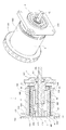
本発明の第1の態様は、図1および図2に示されるように、底部420と内側円筒空路形成体500および外側円筒空路形成体600と複数のマグネットとを有する回転子3と、回転子3に対向するように配備される通電可能な無鉄心の円筒コイル200が固定された固定子2とからなる、底部420と内側円筒空路形成体500とで形成される空間540に外気を取り入れように底部420に複数の吸気孔430が形成され、空間540と連通する、内側円筒空路形成体500と外側円筒空路形成体600とからなるエアギャップ40に通じる複数の排気孔660が外側円筒空路形成体600の底部620に近接する円周に帯状に設けられている無鉄心のブラシレス回転電気機械1における外側円筒空路形成体600の、外側円筒空路形成体600と内側円筒空路形成体500とを接続する接続部に近接する円周に嵌装固定される円環で構成された冷却補助具700であって、外側円筒空路形成体600の排気孔660に一致するように設けられた複数の放射状の連通口720を有する冷却補助具に関するものである。
1 and 2, the first aspect of the present invention includes a
冷却補助具700は、外側円筒空路形成体600に対し、着脱自在に嵌装固定される樹脂製リングからなる円環で構成され、外側円筒空路形成体600の排気孔660に対応する連通口720が形成されており、連通口720は、少なくとも排気孔660の内径Φおよび長さLを有することが好ましい。
The
本発明の第2の態様は、図1および図2に示されるように、無鉄心の円筒コイル200を備えた固定子2を含むブラシレス回転電気機械1を構成する、底部420と内側円筒空路形成体500および外側円筒空路形成体600とを有する回転子3は、底部420と内側円筒空路形成体500とで形成される空間540に外気を取り入れるための底部420に形成された複数の吸気孔430を有し、回転軸100に固定される回転子3に対向するように回転軸100に回転自在に支持された固定子2の円筒コイル200を浮かせた状態で配置される内側円筒空路形成体500と外側円筒空路形成体600とでエアギャップ40を形成し、かつ、エアギャップ40に複数のマグネット4を露出するように装備し、エアギャップ40の閉鎖された外側円筒空路形成体600の底部620に近接する円周にエアギャップ40に通じる複数の排気孔660を帯状に穿設し、排気孔660に対応する複数の放射状の連通口720が設けられた円環からなる冷却補助具700を、排気孔660に連通口720を一致するように外側円筒空路形成体600に嵌装固定した無鉄心の円筒コイル200を備えた固定子2を含むブラシレス回転電気機械1に関するものである。
As shown in FIGS. 1 and 2, the second aspect of the present invention is a bottom 420 and an inner cylindrical air passage forming the brushless rotating
無鉄心の円筒コイル200を備えた固定子2を含むブラシレス回転電気機械1を構成する外側円筒空路形成体600に着脱自在に嵌装固定される樹脂製リングからなる冷却補助具700に形成された連通口720は、外側円筒空路形成体600の排気孔660に対応するように、少なくとも排気孔660の内径Φおよび長さLを有することが好ましい。
It is formed in a
本発明の第1の態様および第2の態様から明らかなように、無鉄心の円筒コイル200を備えた固定子2を含むブラシレス回転電気機械1は、回転子3の回転により発生する回転子3の周囲の圧力差によって、空間540に吸気孔430から外気70を引き込み、回転子3の周囲の圧力差は、空間540に引き込まれた外気70をエアギャップ40に配置される円筒コイル200の内側を流通させ、流通する外気70は、エアギャップ40に露出するように装備された複数のマグネット4および円筒コイル200を冷却し、外側円筒空路形成体600の排気孔660を介し、冷却補助具700の連通口720を経由し、外部に排出させるようにしたことを特徴とする。
As is apparent from the first and second aspects of the present invention, the brushless rotating
本発明の第3の態様は、図1および図2に示されるように、通電可能な無鉄心の円筒コイル200、および、円筒コイル200の一方の端面201が固定されて中心部310に駆動シャフト100が回転自在に連結されている蓋型マウント300を有する固定子2と、駆動シャフト100が中心部410に連結固定されて蓋型マウント300の対極に配備されている、底部420と内側円筒空路形成体500および外側円筒空路形成体600とを有するカップ型マウント400、および、外側円筒空路形成体600の内周面610および/または内側円筒空路形成体500の外周面520に配備されている複数のマグネット4を有する回転子3と、を含み、
カップ型マウント400は、底部420と内側円筒空路形成体500および外側円筒空路形成体600とで第1空隙のエアギャップ40が形成されており、エアギャップ40に、複数のマグネット4を露出するように配備され、円筒コイル200の他方の端面202が底部420との間で隙間42を残して円筒コイル200を浮かせた状態で配置し、カップ型マウント400の開放端面530、630と蓋型マウント300との間に円筒コイル200の内側に位置する空間の第2空隙20、および、円筒コイル200の外側に位置する外気に通じる第3空隙30を有する無鉄心の円筒コイル200を備えた固定子2を含むブラシレス回転電気機械1であって、
カップ型マウント400は、底部420に第2空隙20に通じる吸気孔430を有し、外側円筒空路形成体600の底部620に近接する円周にエアギャップ40に通じる複数の排気孔660を帯状に穿設し、排気孔660に対応する複数の放射状の連通口720を設けた円環で構成する冷却補助具700を、連通口720を排気孔660に一致させて外側円筒空路形成体600に嵌装固定するようにし、回転子3の回転により発生する回転子3の周囲の圧力差によって、吸気孔430から第2空隙20に引き込まれた外気70および第3空隙30からエアギャップ40に引き込まれた外気80は、エアギャップ40内を流通し、エアギャップ40に露出するように配備された複数のマグネット4およびエアギャップ40に配置されている円筒コイル200の両面を冷却し、外側円筒空路形成体600の排気孔660を介し、冷却補助具700の連通口720を経由し、外部に排出されるようにしたことを特徴とする無鉄心の円筒コイル200を備えた固定子2を含むブラシレス回転電気機械1に関するものである。
As shown in FIGS. 1 and 2, the third aspect of the present invention is a non-iron-
In the cup-
The cup-
無鉄心の円筒コイル200を備えた固定子2を含むブラシレス回転電気機械1を構成する外側円筒空路形成体600に着脱自在に嵌装固定される樹脂製リングからなる冷却補助具700に形成された連通口720は、外側円筒空路形成体600の排気孔660に対応するように、少なくとも排気孔660の内径Φおよび長さLを有することが好ましい。
It is formed in a
無鉄心の円筒コイル200を備えた固定子2を含むブラシレス回転電気機械1を構成する通電可能な無鉄心の円筒コイル200は、長手方向に離間された複数の線状部を有する導電性金属シートの複数で構成された積層体構造を有する円筒形であって、導電性金属シートの各々の線状部が絶縁層で覆われていることが好ましい。
An energizable ironless
本発明の第3の態様から明らかなように、無鉄心の円筒コイル200を備えた固定子2を含むブラシレス回転電気機械1は、回転子3の回転により発生する回転子3の周囲の圧力差によって、第2空隙20に吸気孔430から外気70を引き込むと同時に、エアギャップ40に第3空隙30から外気80を引き込み、回転子3の周囲に発生する圧力差は、第2空隙20に引き込まれた外気70をエアギャップ40に配置される円筒コイル200の内側を流通させ、エアギャップ40に引き込まれた外気80を円筒コイル200の外側を流通させ、流通させた外気により、エアギャップ40に露出するように配備された複数のマグネット4およびエアギャップ40に浮かせた状態で配置された円筒コイル200の両面を冷却し、さらに、流通させた外気を、外側円筒空路形成体600の排気孔660を介し、冷却補助具700の連通口720を経由し、外部に排出させることを特徴とする。
As is apparent from the third aspect of the present invention, the brushless rotating
用語として、内側円筒空路形成体および外側円筒空路形成体は通常磁性体からなるので、内側円筒空路形成体をインナーヨークとし、外側円筒空路形成体をアウターヨークとする。また無鉄心の円筒コイルを備えた固定子を含むブラシレス回転電気機械は、コアレス・ブラシレスモータと略すことにする。 In terms of terminology, the inner cylindrical air passage formation body and the outer cylindrical air passage formation body are usually made of a magnetic material, so that the inner cylindrical air passage formation body is an inner yoke and the outer cylindrical air passage formation body is an outer yoke. Further, a brushless rotating electric machine including a stator having a coreless cylindrical coil is abbreviated as a coreless brushless motor.
電動モータの性能の一つである発生トルクT(N・m)は、電機子コイルに流れる電流の強さI(A)に比例し、出力P(W)はトルクT(N・m)と回転角速度ω(rad/s)の積で表される。一方電圧降下で見ると、電源電圧V(V)は電機子コイルに流れる電流I(A)と、電機子コイルの抵抗R(Ω)との積に誘導起電力である逆起電力E0(V)を合算した式と釣り合う。
T=Kt×I・・・(1)
P=T×ω・・・(2)
V=IR+E0・・・(3)
上記の式より、トルクおよび出力を上げるためには、コイル抵抗値を下げることが重要であることがわかる。
The generated torque T (N · m), which is one of the performances of the electric motor, is proportional to the current intensity I (A) flowing through the armature coil, and the output P (W) is the torque T (N · m). It is represented by the product of the rotational angular velocity ω (rad / s). On the other hand, in terms of the voltage drop, the power supply voltage V (V) is the product of the current I (A) flowing through the armature coil and the resistance R (Ω) of the armature coil, and the counter electromotive force E 0 ( It is balanced with the sum of V).
T = Kt × I (1)
P = T × ω (2)
V = IR + E 0 (3)
From the above equations, it can be seen that it is important to reduce the coil resistance value in order to increase the torque and output.
そこで本発明を特徴づける図1に示される本発明のコアレス・ブラシレスモータ1の基本構造について概観すると、基本構造の特徴は、第1に、固定子2を構成する通電可能なコイル体として、導電性金属シートの積層体構造によって成形された円筒コイルを用いたことにある。それは、円筒コイルおよびその製造方法として、例えば特許文献8に記載されているように、長手方向に離間された複数の線状部を有する導電性金属シートの複数で構成された積層体構造を有する円筒形であって導電性金属シートの各々の線状部が絶縁層で覆われており、好ましくは、2層または4層からなる厚さが5mm以下の一定の剛性を有するものである。
Therefore, when the basic structure of the coreless /
基本構造の特徴の第2に、それは、円筒コイルの一方の端面を、固定子2を構成する蓋型マウントの内周面によって閉鎖し、円筒コイルの開放された他方の端面を、回転子3を構成するカップ型マウントの底部と複数のマグネット(永久磁石)4が装備された磁性体からなるアウターヨークおよびインナーヨークとによって、断面ドーナツ状の磁界が形成される第1空隙のエアギャップに浮かせた状態で、挿入配置する構造を有する。
The second feature of the basic structure is that one end surface of the cylindrical coil is closed by the inner peripheral surface of the lid mount constituting the
さらに詳細には、エアギャップに挿入配置されている円筒コイルは、その内周面および外周面を回転子3のアウターヨークの内周面およびインナーヨークの外周面に接しないように、かつ、その他方の端面を、回転子3を構成するカップ型マウントの底部に接しないように、エアギャップ内に僅かの隙間を空け浮かせた状態になる。それは、円筒コイルがこのように配置されるように固定子2および回転子3を駆動シャフトに配置する構造を有するものである。
More specifically, the cylindrical coil inserted and arranged in the air gap has its inner peripheral surface and outer peripheral surface not in contact with the inner peripheral surface of the outer yoke of the
基本構造の特徴の第3に、それは、固定子2と円筒コイルと回転子3とによって、円筒コイルの内側空間の第2空隙20および円筒コイルの外側空間で外気に接する第3空隙30を形成する構造を有するものである。より詳細には、第2空隙20は、回転子3に一体化されたアウターヨークおよびインナーヨークの開放された開放端面と該開放端面に対置する固定子2の内面との間に、固定子2の内面によって閉鎖された円筒コイルの内周面に形成される。当然、その空隙はエアギャップに通じる。
The third feature of the basic structure is that the
回転子3を構成するカップ型マウントの底部に複数の吸気孔が設けられている本発明のコアレス・ブラシレスモータ1を作動させると、回転子3の回転により発生する回転子3の周囲の圧力差によって、吸気孔から第2空隙に外気を引き込むように作用する。また第3空隙は、固定子2の内面によって閉鎖された円筒コイルの外周面にエアギャップと外気との間に形成される。そうなると、円筒コイルの内周面と固定子2の内面とで形成される閉鎖空間となる第2空隙は、エアギャップに連通し、回転子3の内面を経て円筒コイルの外周面と固定子2の内面とアウターヨークの開放端面とで形成される開放空間となる第3空隙とのみ連通させることができる。
When the
本発明のコアレス・ブラシレスモータ1をアウターヨークにエアギャップに通じる排気孔を有しない構成にして作動すると、回転子3の周囲の圧力差によって吸気孔から第2空隙に引き込まれた外気は、円筒コイルの内周面を通り、外周面を経由して第3空隙から外部に排出される。すなわち回転子3の底部に設けられた吸気孔が外気の入り口で、第3空隙が排気のための出口になるためである。
When the coreless /
しかし、本発明のコアレス・ブラシレスモータ1は、エアギャップに通じる排気孔をアウターヨークに穿設し、かつ、排気孔に対応する連通口を有する冷却補助具を、連通口を排気孔に一致させて嵌装固定されたものである。そうなると、回転子3の周囲の圧力差によって、吸気孔から第2空隙に外気を取り込む一方、第3空隙30が排気孔から吸気孔の働きに変わるため、第3空隙30から別途に外気が取り込まれる。いずれの外気もエアギャップを通り、アウターヨークに穿設した複数の排気孔を介し、連通口から外部に排出されることになる。
However, in the coreless /
より明らかなことは、本発明のコアレス・ブラシレスモータ1は、回転子3の回転数が高まるほど、すなわち出力Pが大きくなればなるほど、回転子3の周囲の圧力差も大きくなり、取り込まれる外気量が増大し、冷却効果も増すという画期的な技術的特徴を有する。それは上記した本発明のコアレス・ブラシレスモータ1の基本構造に由来する。すなわち、磁束密度が大きい狭隘のエアギャップに回転数が高まると増大する鉄損が存在しないコアレスの円筒コイルを浮かせた状態で挿入配置し、一方で、閉鎖空間の第2空隙20に取り込まれた外気でエアギャップに配置されている円筒コイルの内周面を冷却し、他方で、その時に形成される負圧状態によってエアギャップに第3空隙から別途に取り込まれた外気で円筒コイルの外周面を冷却し、そして、外気はいずれもアウターヨークの複数の排気孔を介し連通口から外部に排出されるように作用する構造からなる本発明のコアレス・ブラシレスモータとしての特徴に由来する。
More clearly, in the coreless /
[連通口による冷却効果を評価するための測定実験]
本発明の被測定コアレス・ブラシレスモータCPH50の使用領域を48Vに設定した場合の冷却効果を評価するため、被測定コアレス・ブラシレスモータCPH50を作動し、回転子3の周囲に発生する圧力差によって、回転子3を構成する底部420に設けられた複数の吸気孔430および第3空隙30から取り込まれた外気による冷却効果を以下の3パターンに基づき評価した。
[1]比較例A:冷却補助具700を用いることなく、かつ、排気孔660を設けないCPH50を作動させた場合、すなわち、このパターンは、第3空隙30が排気孔としての働きをする場合である。
[2]比較例B:冷却補助具700を用いることなく、吸気孔430から取り込まれた外気および第3空隙30から取り込まれた外気をアウターヨーク600の排気孔660から外部に排出するようにCPH50を作動させた場合、このパターンは、第3空隙30が吸気孔としての働きをする場合である。
[3]本発明の測定例C:吸気孔430から取り込まれた外気および第3空隙30から取り込まれた外気をアウターヨーク600の排気孔660を介し、アウターヨーク600に嵌装固定された冷却補助具700の連通口720から外部に排出するようにCPH50を作動させた場合、このパターンは、第3空隙30が吸気孔としての働きをし、取り込まれた外気が排気孔660を経由し連通口720から外部に排出される場合である。
[Measurement experiment to evaluate the cooling effect of the communication port]
In order to evaluate the cooling effect when the use area of the measured coreless / brushless motor CPH50 of the present invention is set to 48V, the measured coreless / brushless motor CPH50 is operated, and the pressure difference generated around the
[1] Comparative Example A: When the
[2] Comparative Example B: CPH50 so that the outside air taken in from the
[3] Measurement Example C of the Present Invention: Cooling assistance in which the outside air taken in from the
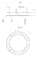
図2は、被測定コアレス・ブラシレスモータCPH50の断面図(a)および正面図(b)を表す。なお、図示されていないが、円筒コイルの温度測定のためのセンサは、円筒コイルの第3空隙に露出した部分の付近に取り付けた。 FIG. 2 shows a cross-sectional view (a) and a front view (b) of the coreless / brushless motor CPH50 to be measured. Although not shown, the sensor for measuring the temperature of the cylindrical coil was attached in the vicinity of the portion exposed to the third gap of the cylindrical coil.
被測定コアレス・ブラシレスモータCPH50について概説すると、第1に、厚みは1.85mmで外径は32.2mmの円筒コイルは、幅6.25mmで長手方向の長さが42.55mmの第1空隙のエアギャップ40に挿入配置される。マグネット4は、断面図(b)に示されるように、厚さ3.5mmの直方体からなる6個のネオジム磁石を長手方向に2.57mmの間隔を空けてアウターヨークの内周面に配備される。
An outline of the measured coreless / brushless motor CPH50 is as follows. First, a cylindrical coil having a thickness of 1.85 mm and an outer diameter of 32.2 mm has a first gap having a width of 6.25 mm and a longitudinal length of 42.55 mm. The
回転子3に一体化されたアウターヨーク600およびインナーヨーク500の開放端面530,630と該開放端面に対置する固定子2の内面との間に、2.5mm幅の第2空隙20および1.5mm幅の第3空隙30が形成されている。また、アウターヨーク600の、アウターヨーク600とインナーヨーク500とを接続する接続部に近接する帯状の円周には直径3mmの排気孔660が24個穿設されている。排気孔660を有しないCPH50を想定するパターンを測定する場合には、これらの排気孔66にアウターヨークの外周面側から樹脂テープを貼り付けることによって、これに対応した。また円筒コイル200の内周面とインナーヨーク500の外周面との間隙は0.5mmであり、円筒コイル200の外周面とネオジム磁石4の内周面との間隙は0.4mmである。
Between the open end surfaces 530 and 630 of the
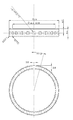
図3に示されるように、アウターヨーク600に嵌装固定される樹脂製リングからなる冷却補助具700は、内径Φが46.4mm、外径Φが62mmであり、アウターヨーク600の排気孔660に対応する24個の連通口720の直径は3.5mmであり、放射状に延びた連通口の長さは7.8mmになる。因みに、アウターヨーク600の24個の排気孔660の直径は3mmであり、長さは3.15mmになる。したがって、排気孔660の長さに連通口720の長さを加えると、外気が排気される通路の長さは10.95mmになる。これにより遠心力による排出圧力はより大きくなり、冷却効果もより高くなる。
As shown in FIG. 3, the
図4は、実験装置の概要図である。本測定実験では、被測定コアレス・ブラシレスモータCPH50の出力軸にトルク計(UNIPULSE TM301)920を接続したトルクセンサ(UNIPULSE UTM II−5Nm)930を介して発電機(m−link CP8048)800を連結し、発電機800が発電する電力を可変負荷(三相PWM方式駆動電源:ICAN TEC BLD750)810を外部可変抵抗器等で消費させることで生じる負荷トルクおよび回転数から導かれる出力動力と被測定コアレス・ブラシレスモータCPH50への入力電力は、駆動電源から供給される電圧と電流と駆動状態の力率によるため、モータ駆動装置900と被測定コアレス・ブラシレスモータCPH50との間に電力計(HIOKI PW3336)910を入れて測定するようにした。
FIG. 4 is a schematic diagram of the experimental apparatus. In this measurement experiment, a generator (m-link CP8048) 800 is connected via a torque sensor (UNIPULSE TMTM-5-5Nm) 930 in which a torque meter (UNIPULSE TM301) 920 is connected to the output shaft of the coreless brushless motor CPH50 to be measured. Then, the output power derived from the load torque and rotation speed generated by consuming the variable load (three-phase PWM drive power supply: ICAN TEC BLD750) 810 with an external variable resistor or the like as the power generated by the
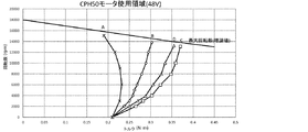
被測定コアレス・ブラシレスモータCPH50のアウターヨーク600の24個の排気孔660の位置に連通口720を合わせ、冷却補助具700をアウターヨーク600にズレ止めして嵌装固定する。測定項目は、CPH50の円筒コイル200の温度上昇の上限(飽和温度)を117℃に設定した負荷トルク、回転数、電流、入力電力の4点である。図5は、これらの条件で、[1]比較例A、[2]比較例B、および、[3]本発明の測定例Cの各負荷トルク(T/Nm)とCPH50の回転数(N/rpm)との関係を表す測定値に基づくグラフである。また図6はそれらの測定値のデータ表である。
The
測定手順は以下の通りである。最初に駆動装置900への入力電力を48Vにセットする。次にCPH50の回転数を任意に設定する。さらに発電機800の可変負荷810による可変抵抗によってトルク計920で負荷トルクT/Nmを調整しながら順次上げていく。次にCPH50の円筒コイル200の温度を測定し、飽和温度117℃に達しないときは、再度負荷トルクT/Nmを調整する。最終的に円筒コイル200の温度が飽和温度117℃に達したときの負荷トルクT/Nmを測定した。
The measurement procedure is as follows. First, the input power to the
[測定実験の評価]
図5のAラインは、アウターヨーク600に穿設した24個の排気孔660を樹脂テープで閉じた場合、すなわち[1]比較例Aの被測定CPH50を構成する円筒コイル200の温度が飽和温度117℃のときの測定値である。図5のAラインの左側領域は、被測定CPH50の正常運転領域になる。したがって、被測定CPH50は、図5の実線で示すAラインの右側領域においては、被測定CPH50の円筒コイルの発熱やマグネットの加熱に伴い性能面から正常運転を期待できなくなる。
[Evaluation of measurement experiment]
The A line in FIG. 5 shows the case where the 24
こうした性能低下を防ぐための技術的手段の一つがアウターヨーク600にエアギャップ40に通じるように穿設した排気孔660によって冷却機能を付加することである。それが[2]比較例Bの場合であり、図5のBラインで表される。具体的には、[2]比較例Bの被測定CPH50を構成する円筒コイル200の温度が飽和温度117℃のときの測定値である。図5のBラインは、図5のAラインに比べ回転全域で負荷トルクが増大し、排気孔660が被測定CPH50の正常運転領域を拡大させたことを示し、排気孔660のない被測定CPH50より冷却効果が高いことがこれで確認される。
One of the technical means for preventing such performance degradation is to add a cooling function by an
図5のCラインは、アウターヨーク600に穿設した24個の排気孔660に対応する放射状の連通口720を有する冷却補助具700をアウターヨーク600に嵌装固定された[3]本発明の測定例Cの被測定CPH50を構成する円筒コイル200の温度が飽和温度117℃のときの測定値である。[2]比較例Bの被測定CPH50との構成上の違いは、図3に示された冷却補助具700を、連通口720を24個の排気孔660に一致させて嵌装固定した点にある。そのことは、外気が排出される通路の長さが、アウターヨークの厚みに一致する排気孔660の長さが3.15mmであったものが、連通口720の長さ7.8mmを加えた10.95mmになったことである。通路の長さが伸びた分だけ遠心力が増すことによって排出される外気の流速が高まり、吸気孔430および第3空隙から取り込まれる外気量が増える結果、[3]本発明の測定例Cの被測定CPH50の冷却効果がさらに一段と高まることがこれで確認される。
C line in FIG. 5 was fitted fixed to the
図7および図8は、駆動装置900への入力電力を24Vにセットした場合のグラフと測定値データ表である。また図9および図10は、駆動装置900への入力電力を36Vにセットした場合のグラフと測定値データ表である。いずれも[3]本発明の測定例Cの被測定CPH50を構成する円筒コイル200の温度が飽和温度117℃のときの測定値をみると、[1]比較例Aおよび[2]比較例Bに比べ、回転全域で負荷トルクが増大し、被測定CPH50の正常運転領域を拡大させていることが確認される。24V、36V、および、48Vに設定された被測定CPH50の正常運転領域は、高速回転になるほど拡大し、冷却効果が高いことがこれでも確認される。
7 and 8 are a graph and a measurement value data table when the input power to the
参考のため、図11に別形状の冷却補助具700’を示す。図3の冷却補助具700との違いは連通口720の長さが異なる点のみである。別形状の冷却補助具700’の連通口720’の長さが3.8mmであり、連通口720の長さ7.8mmの1/2以下である。外気が排出される通路の長さが短い分だけ遠心力が低く排出される外気の流速も小さい。したがって、吸気孔430および第3空隙30から取り込まれる外気量も少ない結果、図5、図7、図9のDラインに示されるように、Cラインの左側に飽和温度117℃のときの測定値が示される。
For reference, FIG. 11 shows a
また、吸気孔430を閉鎖した被測定CPHによるパターンは、今回の測定実験には含まれていない。その場合は、説明するまでもなく、取り込まれる外気が十分でないため、冷却効果は低くなり、飽和温度117℃のときの測定値が図5のAラインより左側に位置することなる。
Further, the pattern by the measured CPH with the
本発明は、好ましい実施形態に関連して記載されたが、当業者であれば、本発明の範囲から逸脱することなく、様々な変更がなされ、均等物がそれについての要素に代替され得ることが理解されるであろう。したがって、本発明を実施するために考慮された最良の実施態様として開示された特定の実施態様に限定されるものではなく、特許請求の範囲に属する全ての実施形態を含むものであることが意図される。 Although the present invention has been described with reference to preferred embodiments, those skilled in the art will recognize that various modifications can be made and equivalents can be substituted for elements thereof without departing from the scope of the invention. Will be understood. Accordingly, it is not intended to be limited to the particular embodiment disclosed as the best mode contemplated for carrying out the invention, but is intended to include all embodiments within the scope of the claims. .
1 無鉄心の円筒コイルを備えた固定子を含むブラシレス回転電気機械またはコアレス・ブラシレスモータ
2 固定子
3 回転子
4 マグネット
20 第2空隙
30 第3空隙
40 第1空隙のエアギャップ
41 内側間隙
42 中間間隙
43 外側間隙
70 第2空隙に引き込まれた外気
80 第3空隙から引き込まれた外気
100 駆動シャフト
200 円筒コイル
201 円筒コイルの(固定)端面
202 円筒コイルの(開放)端面
300 蓋型マウント
310 蓋型マウントの中心部
400 カップ型マウント
410 カップ型マウントの中心部
420 カップ型マウントの底部
430 吸気孔
431 吸気孔フィルタ
500 内側円筒空路形成体またはインナーヨーク
530 内側円筒空路形成体またはインナーヨークの開放端面
540 内側円筒空路形成体またはインナーヨークの内側空間
600 外側円筒空路形成体またはアウターヨーク
630 外側円筒空路形成体またはアウターヨークの開放端面
660 外側円筒空路形成体またはアウターヨークの底部に穿設した排気孔
700 冷却補助具
720 冷却補助具の連通口
800 発電機
810 可変負荷
900 駆動装置
910 電力計
920 トルク計
930 トルクセンサ
1. Brushless rotating electrical machine or coreless brushless motor including a stator with a coreless
20 Second air gap 30
100 Drive shaft
200 Cylindrical coil 201 (fixed)
300
400 Cup-
500 Inner cylindrical air passage formation body or
600 Outer cylindrical air passage forming body or
700
800
900
Claims (10)
前記回転電気機械は、前記回転子の円周に複数の排気孔が穿設されてあり、
前記冷却補助具は、前記複数の排気孔に対応する複数の放射状の連通口を有し、前記円周の位置において前記回転子の外周側に嵌装固定されることを特徴とする冷却補助具。 The rotary electric machine comprising a stator and a rotor are rotor fitted fixed, a cooling aid constituted by a circular ring,
The rotating electrical machine has a plurality of exhaust holes formed in the circumference of the rotor,
The cooling aid, cooling aids, characterized in that said corresponding plurality of exhaust holes have a plurality of radial communication ports is fitted fixed to the outer peripheral side of the rotor at the location of the circumferential .
前記底部は、前記底部と前記内側円筒空路形成体とで形成される空間に外気を取り入れるための複数の吸気孔を有し、
前記固定子は、前記回転軸を回転自在に支持し、
前記内側円筒空路形成体と前記外側円筒空路形成体との間に形成されるエアギャップには、前記円筒コイルが配置され、かつ、前記回転子には、複数のマグネットが前記エアギャップに露出するように装備され、
前記外側円筒空路形成体の、前記内側円筒空路形成体と前記外側円筒空路形成体とを接続する接続部に近接する円周に、前記エアギャップに通じる複数の排気孔が穿設され、
前記排気孔に対応する複数の放射状の連通口が設けられた円環からなる冷却補助具が、前記排気孔の位置に前記連通口の位置を一致するように前記外側円筒空路形成体の外周側に嵌装固定されていることを特徴とする回転電気機械。 Rotation with a stator having a cylindrical coil-free core, wherein arranged so as to face the stator, and a rotor having a bottom and an inner cylindrical flying formed body and the outer cylindrical flying formed body and the rotary shaft, the An electrical machine,
It said bottom portion has a multiple suction holes for taking outside air into the space formed by the said bottom and the inner cylindrical flying formers,
The stator supports the rotating shaft rotatably,
The air gap formed between the front Symbol inner cylinder flying formers the outer cylindrical flying formed body, the cylindrical coil is arranged, and the rotor is exposed a plurality of magnets to the air gap Equipped to
Previous Kisotogawa cylindrical flying formed body, circumferentially adjacent to the connecting portion for connecting the inner cylindrical flying formed body and the outer cylindrical flying formed body, a plurality of exhaust holes communicating with the air gap is bored,
Cooling aid consisting of a circular ring having a plurality of radial communication port corresponding to the exhaust hole is provided, the outer peripheral side of the outer cylindrical flying formed body so as to match the position of the communication port to a position of the exhaust hole A rotating electric machine characterized by being fitted and fixed to .
前記駆動シャフトが中心部に連結固定されて前記蓋型マウントに対向するように配置されている、底部と内側円筒空路形成体および外側円筒空路形成体とを有するカップ型マウント、および、前記外側円筒空路形成体の内周面および/または前記内側円筒空路形成体の外周面に配備されている複数のマグネットを有する回転子と、
を含み、
前記カップ型マウントは、前記内側円筒空路形成体と前記外側円筒空路形成体との間に第1空隙のエアギャップが形成されており、前記エアギャップに、前記複数のマグネットが露出するように配備され、前記円筒コイルの他方の端面が前記内側円筒空路形成体と外側円筒空路形成体とを接続する接続部との間で隙間を残して前記円筒コイルを浮かせた状態で配置され、前記カップ型マウントの開放端面と前記蓋型マウントとの間に前記円筒コイルの内側に位置する空間の第2空隙、および、前記円筒コイルの外側に位置する外気に通じる第3空隙を有する無鉄心の円筒コイルを備えた固定子を含むブラシレス回転電気機械であって、
前記カップ型マウントは、前記底部に前記第2空隙に通じる吸気孔を有し、前記外側円筒空路形成体の前記接続部に近接する円周に前記エアギャップに通じる複数の排気孔が穿設され、前記排気孔に対応する複数の放射状の連通口を設けた円環で構成する冷却補助具が、前記連通口の位置を前記排気孔の位置に一致させて前記外側円筒空路形成体の外周側に嵌装固定されてあり、
前記回転子の回転により発生する前記回転子の周囲の圧力差によって、前記吸気孔から前記第2空隙に引き込まれた外気および前記第3空隙から前記エアギャップに引き込まれた外気は、前記エアギャップ内を流通し、前記エアギャップに露出するように配備された前記複数のマグネットおよび前記エアギャップに配置されている前記円筒コイルの両面を冷却し、前記外側円筒空路形成体の前記排気孔を介し、前記冷却補助具の前記連通口を経由し、外部に排出されるようにしたことを特徴とする無鉄心の円筒コイルを備えた固定子を含むブラシレス回転電気機械。 An ironless cylindrical coil that can be energized, and a stator having a lid-type mount in which one end face of the cylindrical coil is fixed and a drive shaft is rotatably connected to a central portion;
A cup-type mount having a bottom portion, an inner cylindrical air passage forming body and an outer cylindrical air passage forming body, the driving shaft being connected and fixed to a central portion so as to face the lid-type mount, and the outer cylinder A rotor having a plurality of magnets disposed on the inner peripheral surface of the air passage former and / or the outer peripheral surface of the inner cylindrical air passage former;
Including
The cup-shaped mount, the air gap of the first gap is formed between the before and Symbol inner cylinder flying formed body outer cylindrical flying formed body, the air gap, so that the plurality of magnets are exposed And the other end face of the cylindrical coil is disposed in a state where the cylindrical coil is floated leaving a gap between the connecting portion connecting the inner cylindrical air path forming body and the outer cylindrical air path forming body, and the cup A coreless cylinder having a second gap in a space located inside the cylindrical coil and a third gap communicating with the outside air located outside the cylindrical coil between an open end surface of the mold mount and the lid mold mount A brushless rotating electrical machine including a stator with coils,
The cup-type mount has an intake hole that communicates with the second gap at the bottom, and a plurality of exhaust holes that communicate with the air gap are formed in a circumference close to the connection portion of the outer cylindrical air passage forming body. , cooling aids consist of circular ring having a plurality of radial communication port corresponding to the exhaust hole, an outer peripheral side of the outer cylindrical flying former the position of the communication port by matching the position of the exhaust hole Fitted and fixed to
Due to the pressure difference around the rotor generated by the rotation of the rotor, the outside air drawn into the second gap from the suction hole and the outside air drawn into the air gap from the third gap are Cooling both surfaces of the plurality of magnets arranged so as to be exposed to the air gap and the cylindrical coil disposed in the air gap through the exhaust holes of the outer cylindrical air passage formation body A brushless rotating electric machine including a stator having a coreless cylindrical coil that is discharged to the outside through the communication port of the cooling aid.
Priority Applications (2)
| Application Number | Priority Date | Filing Date | Title |
|---|---|---|---|
| JP2017060960A JP6579522B2 (en) | 2017-03-27 | 2017-03-27 | Brushless rotating electrical machine including a stator having a coreless cylindrical coil and a brushless rotating electrical machine including a stator having a coreless cylindrical coil mounted with the cooling assisting tool |
| CN201711239766.5A CN108667198B (en) | 2017-03-27 | 2017-11-30 | Cooling aid and coreless brushless motor |
Applications Claiming Priority (1)
| Application Number | Priority Date | Filing Date | Title |
|---|---|---|---|
| JP2017060960A JP6579522B2 (en) | 2017-03-27 | 2017-03-27 | Brushless rotating electrical machine including a stator having a coreless cylindrical coil and a brushless rotating electrical machine including a stator having a coreless cylindrical coil mounted with the cooling assisting tool |
Publications (3)
| Publication Number | Publication Date |
|---|---|
| JP2018164373A JP2018164373A (en) | 2018-10-18 |
| JP2018164373A5 JP2018164373A5 (en) | 2018-11-29 |
| JP6579522B2 true JP6579522B2 (en) | 2019-09-25 |
Family
ID=63784997
Family Applications (1)
| Application Number | Title | Priority Date | Filing Date |
|---|---|---|---|
| JP2017060960A Active JP6579522B2 (en) | 2017-03-27 | 2017-03-27 | Brushless rotating electrical machine including a stator having a coreless cylindrical coil and a brushless rotating electrical machine including a stator having a coreless cylindrical coil mounted with the cooling assisting tool |
Country Status (2)
| Country | Link |
|---|---|
| JP (1) | JP6579522B2 (en) |
| CN (1) | CN108667198B (en) |
Families Citing this family (1)
| Publication number | Priority date | Publication date | Assignee | Title |
|---|---|---|---|---|
| JP7035915B2 (en) | 2018-09-03 | 2022-03-15 | 信越化学工業株式会社 | Manufacturing method of thin wafer |
Family Cites Families (14)
| Publication number | Priority date | Publication date | Assignee | Title |
|---|---|---|---|---|
| JPH05344680A (en) * | 1992-06-05 | 1993-12-24 | Toshiba Toransupooto Eng Kk | Outer rotor motor for vehicle |
| JP3494056B2 (en) * | 1999-01-25 | 2004-02-03 | 国産電機株式会社 | Outer rotor type magnet generator |
| JP2000328956A (en) * | 1999-05-20 | 2000-11-28 | Honda Motor Co Ltd | Engine power generator |
| JP2001339908A (en) * | 2000-05-30 | 2001-12-07 | Honda Motor Co Ltd | Outer rotor motor generator |
| JP3548143B2 (en) * | 2001-09-06 | 2004-07-28 | 三洋電機株式会社 | Drum type washing machine |
| JP3671398B2 (en) * | 2002-05-16 | 2005-07-13 | 三菱電機株式会社 | Magnet generator |
| JP4728639B2 (en) * | 2004-12-27 | 2011-07-20 | 株式会社デンソー | Electric wheel |
| JP5260824B2 (en) * | 2005-10-20 | 2013-08-14 | 日本電産テクノモータ株式会社 | Outer rotor motor |
| JP5826526B2 (en) * | 2011-06-08 | 2015-12-02 | 株式会社マキタ | Electric tool |
| KR102447418B1 (en) * | 2014-04-23 | 2022-09-27 | 가부시키가이샤 앰링크 | Rotary electrical machine |
| DE112015004041T5 (en) * | 2014-09-04 | 2017-07-13 | M-Link Co., Ltd. | CORELESS ROTATING ELECTRIC MACHINE WITH A STAND CONTAINING A CYLINDRICAL COIL AND COOLING METHOD THEREFOR |
| TWI565198B (en) * | 2015-01-08 | 2017-01-01 | 周文三 | Motor with heat dissipation structure capable ofrestraining temperature therein |
| JP6005886B1 (en) * | 2016-03-03 | 2016-10-12 | 株式会社エムリンク | Iron-free rotating electric machine including a stator having a cylindrical coil and its cooling method |
| CN106253505A (en) * | 2016-08-31 | 2016-12-21 | 无锡星诺电气有限公司 | A kind of efficient intermediate frequency generator of permanent magnetism |
-
2017
- 2017-03-27 JP JP2017060960A patent/JP6579522B2/en active Active
- 2017-11-30 CN CN201711239766.5A patent/CN108667198B/en active Active
Also Published As
| Publication number | Publication date |
|---|---|
| CN108667198A (en) | 2018-10-16 |
| CN108667198B (en) | 2021-12-07 |
| JP2018164373A (en) | 2018-10-18 |
Similar Documents
| Publication | Publication Date | Title |
|---|---|---|
| JP5943333B1 (en) | Iron-free rotating electric machine including a stator having a cylindrical coil and its cooling method | |
| JP6005886B1 (en) | Iron-free rotating electric machine including a stator having a cylindrical coil and its cooling method | |
| US8648514B2 (en) | Rotary electric motor and blower that uses the same | |
| JP2016154440A5 (en) | ||
| JPH0429547A (en) | Ac generator for vehicle | |
| WO2009011460A1 (en) | Rotating electric machine | |
| JP2009005419A (en) | Rotating electric machine | |
| WO2018051589A1 (en) | Electric blower | |
| JP2017022971A (en) | Single-phase motor, airflow generating device, and electric apparatus | |
| JP2015089332A (en) | Semienclosed-type induction motor | |
| JP6007951B2 (en) | Rotating electric machine | |
| JP6579522B2 (en) | Brushless rotating electrical machine including a stator having a coreless cylindrical coil and a brushless rotating electrical machine including a stator having a coreless cylindrical coil mounted with the cooling assisting tool | |
| JP2009033886A (en) | Dynamo-electric machine | |
| CN104218734A (en) | Rotating electrical machine | |
| WO2018051588A1 (en) | Electric blower | |
| JP5989181B2 (en) | Rotating electric machine | |
| JP2022062289A (en) | Electric motor and electric blower | |
| KR100492589B1 (en) | Cooling structure for motor | |
| JP6414092B2 (en) | Rotating electric machine for vehicles | |
| JP2013183508A (en) | Motor |
Legal Events
| Date | Code | Title | Description |
|---|---|---|---|
| A521 | Request for written amendment filed |
Free format text: JAPANESE INTERMEDIATE CODE: A523 Effective date: 20180903 |
|
| A621 | Written request for application examination |
Free format text: JAPANESE INTERMEDIATE CODE: A621 Effective date: 20180903 |
|
| A871 | Explanation of circumstances concerning accelerated examination |
Free format text: JAPANESE INTERMEDIATE CODE: A871 Effective date: 20180903 |
|
| A975 | Report on accelerated examination |
Free format text: JAPANESE INTERMEDIATE CODE: A971005 Effective date: 20181002 |
|
| A131 | Notification of reasons for refusal |
Free format text: JAPANESE INTERMEDIATE CODE: A131 Effective date: 20181218 |
|
| A601 | Written request for extension of time |
Free format text: JAPANESE INTERMEDIATE CODE: A601 Effective date: 20190207 |
|
| A521 | Request for written amendment filed |
Free format text: JAPANESE INTERMEDIATE CODE: A523 Effective date: 20190415 |
|
| TRDD | Decision of grant or rejection written | ||
| A01 | Written decision to grant a patent or to grant a registration (utility model) |
Free format text: JAPANESE INTERMEDIATE CODE: A01 Effective date: 20190723 |
|
| A61 | First payment of annual fees (during grant procedure) |
Free format text: JAPANESE INTERMEDIATE CODE: A61 Effective date: 20190819 |
|
| R150 | Certificate of patent or registration of utility model |
Ref document number: 6579522 Country of ref document: JP Free format text: JAPANESE INTERMEDIATE CODE: R150 |
|
| S111 | Request for change of ownership or part of ownership |
Free format text: JAPANESE INTERMEDIATE CODE: R313113 |
|
| R350 | Written notification of registration of transfer |
Free format text: JAPANESE INTERMEDIATE CODE: R350 |
|
| R250 | Receipt of annual fees |
Free format text: JAPANESE INTERMEDIATE CODE: R250 |
|
| S802 | Written request for registration of partial abandonment of right |
Free format text: JAPANESE INTERMEDIATE CODE: R311802 |
|
| R350 | Written notification of registration of transfer |
Free format text: JAPANESE INTERMEDIATE CODE: R350 |
|
| R250 | Receipt of annual fees |
Free format text: JAPANESE INTERMEDIATE CODE: R250 |