CN103166340A - Rotating electric machines, railway vehicles and electric vehicles equipped with the same - Google Patents
Rotating electric machines, railway vehicles and electric vehicles equipped with the same Download PDFInfo
- Publication number
- CN103166340A CN103166340A CN2012105444387A CN201210544438A CN103166340A CN 103166340 A CN103166340 A CN 103166340A CN 2012105444387 A CN2012105444387 A CN 2012105444387A CN 201210544438 A CN201210544438 A CN 201210544438A CN 103166340 A CN103166340 A CN 103166340A
- Authority
- CN
- China
- Prior art keywords
- rotor
- stator
- air
- holes
- rotating electrical
- Prior art date
- Legal status (The legal status is an assumption and is not a legal conclusion. Google has not performed a legal analysis and makes no representation as to the accuracy of the status listed.)
- Granted
Links
Images


Classifications
-
- H—ELECTRICITY
- H02—GENERATION; CONVERSION OR DISTRIBUTION OF ELECTRIC POWER
- H02K—DYNAMO-ELECTRIC MACHINES
- H02K9/00—Arrangements for cooling or ventilating
- H02K9/02—Arrangements for cooling or ventilating by ambient air flowing through the machine
- H02K9/04—Arrangements for cooling or ventilating by ambient air flowing through the machine having means for generating a flow of cooling medium
- H02K9/06—Arrangements for cooling or ventilating by ambient air flowing through the machine having means for generating a flow of cooling medium with fans or impellers driven by the machine shaft
-
- H—ELECTRICITY
- H02—GENERATION; CONVERSION OR DISTRIBUTION OF ELECTRIC POWER
- H02K—DYNAMO-ELECTRIC MACHINES
- H02K1/00—Details of the magnetic circuit
- H02K1/06—Details of the magnetic circuit characterised by the shape, form or construction
- H02K1/22—Rotating parts of the magnetic circuit
- H02K1/32—Rotating parts of the magnetic circuit with channels or ducts for flow of cooling medium
-
- H—ELECTRICITY
- H02—GENERATION; CONVERSION OR DISTRIBUTION OF ELECTRIC POWER
- H02K—DYNAMO-ELECTRIC MACHINES
- H02K9/00—Arrangements for cooling or ventilating
- H02K9/10—Arrangements for cooling or ventilating by gaseous cooling medium flowing in closed circuit, a part of which is external to the machine casing
-
- Y—GENERAL TAGGING OF NEW TECHNOLOGICAL DEVELOPMENTS; GENERAL TAGGING OF CROSS-SECTIONAL TECHNOLOGIES SPANNING OVER SEVERAL SECTIONS OF THE IPC; TECHNICAL SUBJECTS COVERED BY FORMER USPC CROSS-REFERENCE ART COLLECTIONS [XRACs] AND DIGESTS
- Y02—TECHNOLOGIES OR APPLICATIONS FOR MITIGATION OR ADAPTATION AGAINST CLIMATE CHANGE
- Y02T—CLIMATE CHANGE MITIGATION TECHNOLOGIES RELATED TO TRANSPORTATION
- Y02T10/00—Road transport of goods or passengers
- Y02T10/60—Other road transportation technologies with climate change mitigation effect
- Y02T10/64—Electric machine technologies in electromobility
Landscapes
- Engineering & Computer Science (AREA)
- Power Engineering (AREA)
- Motor Or Generator Cooling System (AREA)
- Motor Or Generator Frames (AREA)
- Iron Core Of Rotating Electric Machines (AREA)
Abstract
Description
技术领域 technical field
本发明涉及旋转电机及具备该旋转电机的铁道车辆以及电动车辆,尤其涉及适合使用设备内的空气和设备外的空气来进行冷却的旋转电机及具备该旋转电机的铁道车辆以及电动车辆。 The present invention relates to a rotating electrical machine, a railway vehicle and an electric vehicle equipped with the rotating electrical machine, and more particularly, to a rotating electrical machine suitable for cooling using air inside and outside the equipment, and a railway vehicle and an electric vehicle including the rotating electrical machine. the
背景技术 Background technique
通常,作为旋转电机的冷却方法,使用利用配设在设备内的内部风扇使设备内的空气(内部气体)循环来进行冷却、或者利用配设在设备外的外部风扇使设备外的空气(外部气体)向设备外表面流通来进行冷却、或者并用前者和后者来进行冷却这三种方法。 Generally, as a cooling method for a rotating electric machine, cooling is performed by circulating air (internal air) inside the equipment with an internal fan installed in the equipment, or circulating air outside the equipment (external air) with an external fan installed outside the equipment. Gas) is circulated to the outer surface of the equipment for cooling, or the former and the latter are used for cooling. the
上述的旋转电机的冷却方法在专利文献1至4中得以公开。专利文献1及2所公开的旋转电机的冷却方法的特征在于,并用了利用配设在设备内的内部风扇使内部气体循环来进行冷却的方法和利用配设在设备外的外部风扇使外部气体向设备外表面流通来进行冷却的方法。另外,专利文献3及4所公开的旋转电机的冷却方法的特征在于,使外部气体向旋转电机的内周部流通。
The above-mentioned cooling methods for rotating electric machines are disclosed in
【在先技术文献】 【Prior technical literature】
【专利文献】 【Patent Literature】
【专利文献1】日本特开2003-143809号公报 [Patent Document 1] Japanese Unexamined Patent Publication No. 2003-143809
【专利文献2】日本特开平9-149599号公报 [Patent Document 2] Japanese Patent Application Laid-Open No. 9-149599
【专利文献3】日本特开2006-271081号公报 [Patent Document 3] Japanese Patent Laid-Open No. 2006-271081
【专利文献4】日本特开平6-6958号公报 [Patent Document 4] Japanese Patent Application Laid-Open No. 6-6958
然而,在专利文献1及2所记载的冷却中,转子的冷却仅通过内部气体的循环来进行,因此存在内部气体在循环中变得高温而使转子的温度上升的问题。
However, in the cooling described in
进而,在为转子上配置有永磁铁的永磁铁式旋转电机的情况下,若内 部气体在循环中变得高温,则永磁铁可能会发生高温消磁,因此需要对转子效率良好地进行冷却。 Furthermore, in the case of a permanent magnet type rotating electrical machine in which permanent magnets are disposed on the rotor, if the internal air becomes high temperature during circulation, the permanent magnets may be demagnetized at high temperature, so the rotor needs to be cooled efficiently. the
另外,在专利文献3及4所记载的冷却中,仅使外部气体流通,而没有使对定子的线圈端部进行冷却的内部气体循环,因此存在定子的线圈端部变得高温的问题。
In addition, in the cooling described in
发明内容 Contents of the invention
本发明鉴于上述点而提出,其目的在于提供一种旋转电机及具备该旋转电机的铁道车辆以及电动车辆,所述旋转电机中当然不会出现内部气体变得高温的情况,并且能够防止定子的线圈端部变得高温,即使在所述旋转电机为永磁铁式的情况下,也不会出现永磁铁发生高温消磁的情况,从而能够提高冷却性能。 The present invention has been made in view of the above points, and an object of the present invention is to provide a rotating electrical machine, a railway vehicle and an electric vehicle equipped with the rotating electrical machine, which can prevent the temperature of the internal gas from becoming high in the rotating electrical machine and prevent the stator from becoming hot. The coil end becomes high temperature, and even if the rotating electric machine is a permanent magnet type, the permanent magnet does not demagnetize at high temperature, and the cooling performance can be improved. the
为了达成上述目的,本发明的旋转电机包括定子和在该定子的内径侧与该定子隔开规定的空隙而对置配置的转子,所述定子具备定子铁心、在该定子铁心的内径侧沿轴向延伸且在周向上隔开规定间隔而形成的多个定子槽、安装在该多个定子槽内的定子线圈,所述转子具备转子铁心、在该转子铁心的外周侧沿轴向延伸且在周向上隔开规定间隔而形成的多个转子槽、插入到该转子槽中的磁场构件,所述旋转电机的特征在于,在所述转子铁心上设有用于使设备外的空气流通的外部气体通风用的孔和用于使设备内的空气流通的内部气体通风用的孔。 In order to achieve the above objects, a rotating electric machine according to the present invention includes a stator and a rotor disposed opposite to the stator on the inner diameter side of the stator with a predetermined gap therebetween, and the stator includes a stator core along an axis on the inner diameter side of the stator core. A plurality of stator slots extending in the circumferential direction and formed at predetermined intervals in the circumferential direction, and stator coils installed in the plurality of stator slots. A plurality of rotor slots formed at predetermined intervals in the circumferential direction, and a field member inserted into the rotor slots, wherein the rotor core is provided with external air for circulating air outside the equipment. Holes for ventilation and holes for internal air ventilation to circulate the air inside the equipment. the
另外,为了达成上述目的,本发明的铁道车辆具备台车、旋转电机、增速齿轮和车轮,所述旋转电机经由所述增速齿轮来驱动所述车轮,所述铁道车辆的特征在于,所述旋转电机为上述结构的旋转电机。 In addition, in order to achieve the above object, the railway vehicle of the present invention includes a trolley, a rotating electrical machine, a speed-up gear, and wheels, and the rotating machine drives the wheels through the speed-up gear, and the railway vehicle is characterized in that the The rotating electric machine is a rotating electric machine having the above-mentioned structure. the
另外,为了达成上述目的,本发明的电动车辆具备车身、车轮、车轴和旋转电机,通过与所述车轴直接连结的所述旋转电机来驱动所述车轮,所述电动车辆的特征在于,所述旋转电机为上述结构的旋转电机。 In addition, in order to achieve the above object, the electric vehicle of the present invention includes a vehicle body, wheels, an axle, and a rotating electrical machine, and the wheels are driven by the rotating electrical machine directly connected to the axle, and the electric vehicle is characterized in that the The rotating electric machine is a rotating electric machine having the above-mentioned structure. the
【发明效果】 【Invention effect】
根据本发明,当然不会出现内部气体变得高温的情况,且能够防止定子的线圈端部变得高温,即使在所述旋转电机为永磁铁式的情况下,也不会出现永磁铁发生高温消磁的情况,且由于冷却性能得以提高,从而能够 有助于旋转电机的小型化。 According to the present invention, of course, the internal gas does not become high temperature, and the coil end of the stator can be prevented from becoming high temperature, and even in the case where the rotating electric machine is a permanent magnet type, the permanent magnet does not become high temperature. demagnetization, and since the cooling performance is improved, it can contribute to the miniaturization of rotating electrical machines. the
另外,通过具备该小型化了的旋转电机,由此能够获得输出大的铁道车辆或电动车辆。 In addition, by including the miniaturized rotating electrical machine, it is possible to obtain a railway vehicle or an electric vehicle with a large output. the
附图说明 Description of drawings
图1是表示发明的旋转电机的实施例1的剖视图。
Fig. 1 is a sectional
图2是图1的沿着A-A′线的剖视图。 Fig. 2 is a cross-sectional view along line A-A' of Fig. 1 . the
图3是表示本发明的旋转电机的实施例2的转子的立体图。
Fig. 3 is a perspective view showing a rotor of
图4是表示本发明的旋转电机的实施例3的转子的上部剖视图。
Fig. 4 is an upper cross-sectional view showing a rotor of
图5是表示本发明的旋转电机的实施例4的转子的上部剖视图。
Fig. 5 is an upper cross-sectional view showing a rotor of
图6是表示本发明的旋转电机的实施例5的转子的上部剖视图。
Fig. 6 is an upper sectional view showing a rotor of
图7是表示本发明的旋转电机的实施例6即永磁铁式旋转电机的剖视图。 Fig. 7 is a sectional view showing a permanent magnet type rotating electrical machine according to Embodiment 6 of the rotating electrical machine of the present invention. the
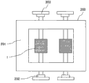
图8是表示搭载有表示本发明的实施例7的本发明的旋转电机的铁道车辆的结构图。 Fig. 8 is a structural view showing a railway vehicle equipped with a rotating electrical machine according to the present invention representing a seventh embodiment of the present invention. the
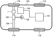
图9是表示搭载有表示本发明的实施例8的本发明的旋转电机的电气机动车的结构图。 Fig. 9 is a configuration diagram showing an electric vehicle equipped with a rotating electrical machine according to the present invention representing an eighth embodiment of the present invention. the
图10是对本发明的实施例1的设有外部气体通风用的孔的情况与现有技术的没有设置外部气体通风用的孔的情况下的线圈端处的温度上升的降低效果进行比较而示出的图。 10 is a comparison of the reduction effect of the temperature rise at the coil end in the case of providing the hole for external air ventilation in Example 1 of the present invention and the case of not providing the hole for external air ventilation in the prior art. out of the picture. the
具体实施方式 Detailed ways
以下,参照图示的实施例对本发明的旋转电机进行说明。需要说明的是,对各实施例中相同的结构部件使用同一符号。 Hereinafter, the rotating electric machine of the present invention will be described with reference to the illustrated embodiments. It should be noted that the same symbols are used for the same structural components in the various embodiments. the
【实施例1】 [Example 1]
图1及图2表示本发明的旋转电机的实施例1即感应电动机。需要说明的是,图2中省略了壳体的图示。 1 and 2 show an induction motor which is a first embodiment of a rotating electric machine according to the present invention. It should be noted that the illustration of the housing is omitted in FIG. 2 . the
如该图所示,作为感应电动机的旋转电机1包括定子2和转子3。定子2大致包括定子铁心4;设置在该定子铁心4的内周侧,且在周向上隔开规定间隔地形成,并且卷绕在沿轴向延伸的多个定子槽12上的多相的 定子绕组5;用内周面来保持定子铁心4的壳体11。
As shown in the figure, a rotary
层叠有多片电磁钢板的定子铁心4具备:圆筒状的磁轭部21(或者称作芯背(core back)部);从磁轭部21的内周表面向径向内侧突出,沿着磁轭部21的内周面而沿轴向延伸的多个齿部22。齿部22沿着磁轭部21的内周面在周向上等间隔地配置。另外,在定子2的齿部22之间配置有用于供上述的定子绕组5卷绕的定子槽12。
The
另外,转子3以与定子铁心4在径向上具有规定间隙的方式配置,且大致包括:层叠有多片电磁钢板的转子铁心7;设置在该转子铁心7的外周侧,在周向上隔开规定间隔地形成,并且插入到沿轴向延伸的多个转子槽6中的作为磁场构件的转子杆13;使各转子杆13在两轴端短路的由导体构成的端环14;与转子铁心7嵌合的轴8,其中,轴8由轴承10保持为能够旋转。
In addition, the
另外,转子铁心7被用于按压转子铁心7的按压板15在轴向上固定,进而,在转子3上安装有内部气体通风用的内部风扇50和外部气体通风用的外部风扇51。
The
上述轴承10由尾架9支承,尾架9固定在壳体11上。转子3沿顺时针方向、逆时针方向旋转,作为电动机而进行运转。
Above-mentioned
并且,在本实施例中,用于使外部气体流通的外部气体通风用的孔16和用于使内部气体向外侧流通的内部气体通风用的孔17a以在周向上隔开规定间隔且沿轴向贯通的方式在转子3的转子铁心7上形成多个。另外,在用于按压转子铁心7的按压板15上也同样地形成有外部气体通风用的孔16和用于使内部气体流通的内部气体通风用的孔17a。该外部气体通风用的孔16位于比内部气体通风用的孔17a靠转子3的内周侧的位置。
In addition, in this embodiment, the
即,本实施例的转子铁心7形成为打通有外部气体通风用的孔16、内部气体通风用的孔17a、转子槽6及轴8的孔的结构。并且,通过层叠打通有外部气体通风用的孔16、内部气体通风用的孔17a、转子槽6及轴8的孔的电磁钢板,并在贯通着的转子槽6和供轴穿过的孔中插入转子杆13及轴8,由此来构成转子3。
That is, the
接着,参照图1对本实施例中的使用了内部气体及外部气体的通风路径(冷却路径)进行说明。 Next, a ventilation path (cooling path) using internal air and external air in this embodiment will be described with reference to FIG. 1 . the
如该图所示,外部气体56在外部风扇51的作用下从外部气体入气口54进入,进入到空气积存部52后,在外部风扇51的离心力的作用下将粉尘从粉尘排出口53排出。
As shown in the figure, the
接着,被除去粉尘后的外部气体56在外部风扇51的作用下通过位于转子3的内周部的外部气体通风用的孔16,从外部气体排出口55排出。此时,外部气体56穿过转子铁心7来冷却转子铁心7、转子杆13及内部气体57。另一方面,内部气体57在内部风扇50的作用下通过位于定子绕组5的轴向端部的线圈端18及端环14,到达内部气体通风用通道17b。此时,内部气体57对线圈端18及端环14进行冷却。
Next, the
接着,内部气体57通过内部气体通风用通道17b,并通过位于相反的轴端的线圈端18及端环14。此时,内部气体57穿过壳体11而被外部气体56冷却。被外部气体56冷却后的内部气体57对线圈端18及端环14进行冷却。进而,通过了线圈端18及端环14的内部气体57穿过位于转子3的内周部的内部气体通风用的孔17a而在设备内进行循环。此时,内部气体57穿过转子铁心7(通过热传导)而对转子杆13进行冷却。进而,内部气体57穿过转子铁心7与在外部气体通风用的孔16中流通的外部气体56进行热交换而被冷却。
Next, the
即,在本实施例中,内部气体57对线圈端18及端环14进行冷却,外部气体56对转子3的转子铁心7、转子杆13及内部气体57进行冷却。
That is, in this embodiment, the
通过这样的本实施例的结构,由此当然不会产生内部气体变得高温的情况,且能够防止定子的线圈端部变得高温,由于冷却性能得以提高,因此能够有助于旋转电机的小型化。 With the structure of this embodiment, of course, the internal air does not become high temperature, and the coil end portion of the stator can be prevented from becoming high temperature. Since the cooling performance is improved, it can contribute to the miniaturization of the rotating electrical machine. change. the
即,根据本实施例,由于空气温度降低,因此相应地能够减小旋转电机整体。即,若旋转电机的轴向长度相同,则能够减小径向长度,若径向长度相同,则能够减小轴向长度,因此能够有助于旋转电机的小型化。 That is, according to the present embodiment, since the air temperature is lowered, the size of the entire rotary electric machine can be reduced accordingly. That is, if the axial lengths of the rotating electrical machines are the same, the radial length can be reduced, and if the radial lengths are the same, the axial length can be reduced, thus contributing to miniaturization of the rotating electrical machines. the
需要说明的是,在上述的实施例中,外部气体通风用的孔16和内部气体通风用的孔17a在周向上隔开规定间隔而形成多个,但这两种孔只要至少具有一个就能够达到效果。
It should be noted that, in the above-mentioned embodiment, the
图10是对本发明的实施例1的设有外部气体通风用的孔的情况和现有技术的没有设置外部气体通风用的孔的情况下的线圈端处的温度上升 的降低效果进行比较而示出的图。 Fig. 10 is a comparison of the reduction effect of the temperature rise at the coil end in the case where the hole for external air ventilation is provided in Example 1 of the present invention and the case of not providing the hole for external air ventilation in the prior art. out of the picture. the
如该图所示,可知实施例1的设有外部气体通风用的孔的情况与现有技术的没有设置外部气体通风用的孔的情况相比,能够将线圈端的温度上升降低大约14K左右。 As shown in the figure, it can be seen that the temperature rise at the coil end can be reduced by about 14K in Example 1 with holes for outside air ventilation, compared with the conventional case without holes for outside air ventilation. the
【实施例2】 【Example 2】
接着,使用图3对本发明的旋转电机的实施例2进行说明。图3中省略了定子2、壳体11、轴8、轴承10、转子杆13及端环14的图示。
Next,
如该图所示,实施例2与实施例1的不同之处在于,在转子铁心7上沿周向被实施扭斜(skew),并且在外部气体通风用的孔16及内部气体通风用的孔17a的入口附近的按压板15上安装有叶片20这些点。需要说明的是,19表示轴孔。
As shown in the figure, the difference between
根据这样的本实施例,由于在转子铁心7上实施有扭斜且在按压板15上安装有叶片20,因此在转子3旋转时,通过叶片20将空气向外部气体通风用的孔16及内部气体通风用的孔17a导入。另外,通过使转子铁心7扭斜,由此内部气体通风用的孔16及内部气体通风用的孔17a也被扭斜,能够减小孔部的空气阻力,从而增加风量。因此,能够形成为不需要用于内部气体通风及外部气体通风的内部风扇50及外部风扇51这样的机构,获得与实施例1同样的效果,从而能够有助于旋转电机的进一步小型化。
According to this embodiment, since the
【实施例3】 [Example 3]
接着,使用图4对本发明的旋转电机的实施例3进行说明。图4中省略了定子2、轴承10及壳体11的图示。
Next,
如该图所示,实施例3与实施例1的不同之处在于,安装在转子铁心7上的内部风扇50和外部风扇51形成为一体的结构这一点。该一体结构的内部风扇50和外部风扇51安装在按压板15上。
As shown in the drawing, the third embodiment differs from the first embodiment in that the
根据这样的本实施例,当然能够获得与实施例1同样的效果,通过将内部风扇50和外部风扇51形成为一体结构,由此能够增加风量,且与实施例1比较,结构变得简单,能够实现低成本化。
According to such this embodiment, the same effect as that of
【实施例4】 【Example 4】
接着,使用图5对本发明的旋转电机的实施例4进行说明。图5中省略了定子2、轴承10及壳体11的图示。
Next,
如该图所示,实施例4与实施例1的不同之处在于,在转子铁心7的按压板15上安装的内部风扇50设置在转子3的一方的轴端且外部风扇51设置在转子3的另一方的轴端这一点。
As shown in the figure, the difference between
根据这样的实施例,当然能够获得与实施例1同样的效果,且通过将内部风扇50和外部风扇51配置在转子3的两轴端,由此能够有效地灵活运用轴向端部的布局,能够有助于旋转电机的进一步小型化。
According to such an embodiment, of course, the same effect as that of
需要说明的是,内部风扇50和外部风扇51也可以分别与配置在转子铁心7的轴向两端且从轴向上按压该转子铁心7的按压板15一体地构成。
It should be noted that the
【实施例5】 【Example 5】
接着,使用图6对本发明的旋转电机的实施例5进行说明。图6中省略了定子2、轴承10、壳体11及外部风扇51的图示。
Next,
如该图所示,实施例5与实施例1的不同之处在于,外部气体通风用的孔16比内部气体通风用的孔17a靠转子3的外周侧这一点。
As shown in the figure, the fifth embodiment is different from the first embodiment in that the
通过这样的本实施例的结构,由此被风扇取入的外部气体通过按压板15而被向外部气体通风用的孔16引导。此时,在按压板15上从内周侧朝向外周侧方向的径向上存在倾斜贯通孔15a,通过该倾斜贯通孔15a使外部气体进入位于转子3的外周部的外部气体通风用的孔16中。另外,通过外部气体通风用的孔16后的外部气体向轴向相反侧的按压板15流通,而通过倾斜贯通孔15b从外周侧朝向内周侧方向的径向上向设备外排出。
With the configuration of this embodiment, the outside air taken in by the fan passes through the
另一方面,通过内部风扇50而循环的内部气体在具有从外周侧朝向内周侧方向的径向上倾斜开设的倾斜贯通孔15c的按压板15的作用下进入位于转子3的内周侧的内部气体通风用的孔17a中。通过内部气体通风用的孔17a后的内部气体向轴向相反侧的具有从内周侧朝向外周侧方向的径向上倾斜开设的倾斜贯通孔15d的按压板15流通。
On the other hand, the internal air circulated by the
根据这样的本实施例,当然能够获得与实施例1同样的效果,且由于能够在发热大的转子杆13的附近配置外部气体通风用的孔17a,因此能够有效地进行转子杆13的冷却,能够提高旋转电机的冷却性能。
According to such this embodiment, it is obvious that the same effect as that of
【实施例6】 【Example 6】
接着,使用图7对本发明的旋转电机的实施例6进行说明。图7表示本发明的旋转电机为永磁铁式旋转电机的情况。 Next, Embodiment 6 of the rotating electric machine of the present invention will be described using FIG. 7 . Fig. 7 shows a case where the rotating electrical machine of the present invention is a permanent magnet type rotating electrical machine. the
如该图所示,实施例6与实施例1的不同之处在于,在实施例1中,作为感应电机的例子,将转子杆用于转子3,但在本实施例中,取代转子杆而将永磁铁23用于转子3。
As shown in the figure, Embodiment 6 differs from
即,在本实施例中,在转子铁心7的磁铁插入孔中以在周向上隔开规定间隔且沿轴向延伸的方式设置有多个作为磁场构件的永磁铁23。其它结构与图1的结构同样。
That is, in this embodiment, a plurality of
根据这样的本实施例,当然能够获得与实施例1同样的效果,且通过使外部气体56通过外部气体通风用的孔16且使内部气体57通过内部气体通风用的孔17a,由此能够抑制永磁铁23的发热,因此不存在永磁铁23发生高温消磁的可能性,并且由于还能够进行内部气体57的冷却,因此能够提高永磁铁式旋转电机的冷却性能。
According to such this embodiment, of course, the same effect as that of
需要说明的是,本发明当然能够适用于分布卷绕方式的旋转电机或集中卷绕方式的旋转电机这两者。 It should be noted that, of course, the present invention can be applied to both a rotating electric machine of a distributed winding system and a rotating electric machine of a concentrated winding system. the
【实施例7】 【Example 7】
接着,作为本发明的实施例7,使用图8对使用了本发明的上述各实施例中的一个旋转电机的铁道车辆进行说明。 Next, as a seventh embodiment of the present invention, a railway vehicle using one rotating electrical machine in each of the above-described embodiments of the present invention will be described with reference to FIG. 8 . the
如该图所示,铁道车辆200在台车201上具备实施例1至6中的任一种旋转电机1、增速齿轮202、车轮203,旋转电机1经由增速齿轮202来驱动车轮203。
As shown in the figure, a
需要说明的是,旋转电机1在本实施例中设有两台,但也可以搭载一台或两台以上的多台来进行驱动。另外,在以上的说明中,对将旋转电机1用于铁道车辆200的车轮203的驱动的例子进行了说明,但旋转电机可以在电动建筑机械用的驱动装置及其它所有的驱动装置中使用。
In addition, although two rotating
根据这样的本实施例,通过将本发明的旋转电机适用于电动车辆、尤其是铁道车辆,由此能够实现旋转电机的小型化,因此能够提高输出大的铁道车辆。 According to such this embodiment, by applying the rotating electrical machine of the present invention to electric vehicles, especially railway vehicles, the size of the rotating electrical machine can be reduced, so that a high-power railway vehicle can be improved. the
【实施例8】 【Example 8】
接着,作为本发明的实施例8,使用图9对适用了本发明的上述各实施例中的任一种旋转电机的电气机动车进行说明。 Next, as an eighth embodiment of the present invention, an electric vehicle to which any one of the rotating electrical machines in the above-described embodiments of the present invention is applied will be described using FIG. 9 . the
如该图所示,电气机动车的车身100由四个车轮110、112、114、116 支承。该电气机动车为前轮驱动式,因此在前方的车轴154上直接连结安装有实施例1至6中的任一种旋转电机1。
As shown in the figure, the
旋转电机1通过控制装置130来控制驱动转矩。作为控制装置130的动力源设置有蓄电池151,从该蓄电池151将电力经由控制装置130向旋转电机1供给,从而驱动旋转电机1而使车轮110、114旋转。转向盘150的旋转通过由转向齿轮152、拉杆及转向臂等构成的传递机构向两个车轮110、114传递,从而改变车轮的角度。
The rotating
根据这样的本实施例,若将本发明的旋转电机适用于电动车辆、尤其是电气机动车,则能够实现旋转电机的小型化,因此能够提供输出大的电气机动车。 According to this embodiment, if the rotating electrical machine of the present invention is applied to an electric vehicle, especially an electric vehicle, the size of the rotating electrical machine can be reduced, so that an electric vehicle with a large output can be provided. the
【符号说明】 【Symbol Description】
1…旋转电机 1…rotating motor
2…定子 2…Stator
3…转子 3…Rotor
4…定子铁心 4...Stator core
5…定子绕组 5... Stator winding
6…转子槽 6...rotor slot
7…转子铁心 7...Rotor core
8…轴 8…axis
9…尾架 9... Tailstock
10…轴承 10…Bearing
11…壳体 11…shell
12…定子槽 12...Stator slot
13…转子杆 13…rotor rod
14…端环 14...end ring
15…按压板 15...press plate
15a、15b、15c、15d…倾斜贯通孔 15a, 15b, 15c, 15d... Inclined through holes
16…外部气体通风用的孔 16...holes for external air ventilation
17a…内部气体通风用的孔 17a...holes for internal gas ventilation
17b…内部气体通风用通道 17b... Passages for internal gas ventilation
18…线圈端 18...coil end
19…轴孔 19... shaft hole
20…叶片 20… blades
21…磁轭部 21...Yoke part
22…齿部 22...tooth part
23…永磁铁 23…Permanent magnet
50…内部风扇 50…Internal fan
51…外部风扇 51…external fan
52…空气积存部 52...Air storage unit
53…粉尘排出口 53…Dust outlet
54…外部气体入气口 54...External gas inlet port
55…外部气体排出口 55...External air outlet
56…外部气体 56…external gas
57…内部气体 57…Internal gas
100…车身 100...body
110、112、114、116、203…车轮130…控制装置
110, 112, 114, 116, 203...
150…转向盘 150…Steering wheel
151…蓄电池 151…Battery
152…转向齿轮 152…Steering gear
154…车轴 154…Axle
200…铁道车辆 200…railway vehicles
201…台车 201…Trolley
202…增速齿轮。 202…increasing gear. the
Claims (13)
Applications Claiming Priority (2)
| Application Number | Priority Date | Filing Date | Title |
|---|---|---|---|
| JP2011274046A JP5879116B2 (en) | 2011-12-15 | 2011-12-15 | Rotating electric machine, railway vehicle including the same, and electric vehicle |
| JP2011-274046 | 2011-12-15 |
Publications (2)
| Publication Number | Publication Date |
|---|---|
| CN103166340A true CN103166340A (en) | 2013-06-19 |
| CN103166340B CN103166340B (en) | 2015-07-22 |
Family
ID=47358008
Family Applications (1)
| Application Number | Title | Priority Date | Filing Date |
|---|---|---|---|
| CN201210544438.7A Expired - Fee Related CN103166340B (en) | 2011-12-15 | 2012-12-14 | Rotating electric machine, rail vehicle and electric vehicle equipped therewith |
Country Status (3)
| Country | Link |
|---|---|
| EP (1) | EP2605380B1 (en) |
| JP (1) | JP5879116B2 (en) |
| CN (1) | CN103166340B (en) |
Cited By (14)
| Publication number | Priority date | Publication date | Assignee | Title |
|---|---|---|---|---|
| CN104218736A (en) * | 2014-10-10 | 2014-12-17 | 永济新时速电机电器有限责任公司 | Self-ventilation asynchronous motor with large induced draught fan |
| CN104659942A (en) * | 2013-11-19 | 2015-05-27 | 东芝三菱电机产业系统株式会社 | Rotor Of Rotary Motor |
| CN106104975A (en) * | 2014-03-05 | 2016-11-09 | 拉普兰塔理工大学 | Electricity turbine and power plant |
| CN108566043A (en) * | 2018-05-24 | 2018-09-21 | 深圳市贝优通新能源技术开发有限公司 | A kind of New energy automobile motor of good heat dissipation effect |
| CN108702046A (en) * | 2016-02-22 | 2018-10-23 | 西门子股份公司 | The rotor of the electric rotating machine of permanent-magnet-field and its application |
| WO2019223043A1 (en) * | 2018-05-25 | 2019-11-28 | 苏州优德通力科技有限公司 | Air-cooled anti-spray motor structure |
| CN111725928A (en) * | 2019-03-22 | 2020-09-29 | 东芝三菱电机产业系统株式会社 | Rotating electric machine and rotor shaft |
| CN113937953A (en) * | 2021-10-22 | 2022-01-14 | 中车株洲电机有限公司 | Active air supply cooling permanent magnet motor and electric locomotive |
| CN113949188A (en) * | 2021-10-22 | 2022-01-18 | 中车株洲电机有限公司 | Rotor air-cooled permanent magnet motor and electric locomotive |
| CN116231912A (en) * | 2021-12-02 | 2023-06-06 | 中车永济电机有限公司 | High-power fully enclosed self-ventilated traction motor for high-speed EMU |
| CN116827017A (en) * | 2023-06-23 | 2023-09-29 | 常州工学院 | A heat dissipation-enhanced guide vane for a rotor axial air-cooled induction motor and its optimization method |
| CN116846115A (en) * | 2023-06-29 | 2023-10-03 | 中车永济电机有限公司 | a motor |
| WO2024051047A1 (en) * | 2022-09-09 | 2024-03-14 | 中车株洲电机有限公司 | Motor stator structure and motor |
| CN118353189A (en) * | 2024-06-20 | 2024-07-16 | 浙江大学 | Motor |
Families Citing this family (15)
| Publication number | Priority date | Publication date | Assignee | Title |
|---|---|---|---|---|
| JP6016722B2 (en) * | 2013-07-03 | 2016-10-26 | 三菱電機株式会社 | Electric motor core, rotary electric motor, and linear motor |
| CN103607073B (en) * | 2013-11-30 | 2015-11-04 | 永济新时速电机电器有限责任公司 | The independent three wind path structure motors of high efficiency cooling heat radiation |
| DE102014101039A1 (en) | 2014-01-29 | 2015-07-30 | Dr. Ing. H.C. F. Porsche Aktiengesellschaft | Electric machine |
| US10161416B2 (en) * | 2014-06-02 | 2018-12-25 | Hamilton Sundstrand Corporation | Rotary machine heat sink |
| JP2017208874A (en) * | 2016-05-16 | 2017-11-24 | 株式会社日立製作所 | Rotary electric machine, rotary electric machine drive system, and railway vehicle |
| DE102016210930B4 (en) | 2016-06-20 | 2021-10-07 | Vitesco Technologies GmbH | Electric machine |
| EP3396816A1 (en) * | 2017-04-27 | 2018-10-31 | Hitachi, Ltd. | Rotary electric machine, rotary electric machine driving system and railway vehicle |
| JP7339882B2 (en) * | 2019-12-26 | 2023-09-06 | 株式会社日立製作所 | Wheel built-in electric device |
| CN112713712A (en) * | 2020-12-14 | 2021-04-27 | 中车永济电机有限公司 | Direct drive motor of oil field winch |
| EP4016813A1 (en) * | 2020-12-17 | 2022-06-22 | Rolls-Royce Deutschland Ltd & Co KG | Electric motor with a cooling device |
| DE102020216225A1 (en) * | 2020-12-18 | 2022-06-23 | Zf Friedrichshafen Ag | Electrical machine for driving a motor vehicle |
| FR3128078A1 (en) | 2021-10-12 | 2023-04-14 | Nidec Psa Emotors | Flange for rotating electrical machine |
| DE102021212248A1 (en) | 2021-10-29 | 2023-05-04 | Valeo Eautomotive Germany Gmbh | Rotor for an electric machine with improved cooling |
| WO2024252571A1 (en) * | 2023-06-07 | 2024-12-12 | 三菱電機株式会社 | Rotary electrical machine |
| EP4496189A1 (en) * | 2023-07-18 | 2025-01-22 | ALSTOM Holdings | Electric traction motor for a vehicle |
Citations (5)
| Publication number | Priority date | Publication date | Assignee | Title |
|---|---|---|---|---|
| GB328661A (en) * | 1928-11-05 | 1930-05-05 | Donald Bright Hoseason | Improvements in electric motors |
| GB467527A (en) * | 1936-03-27 | 1937-06-18 | Mather & Platt Ltd | Improvements relating to the cooling of dynamo electric machines |
| CN2572651Y (en) * | 2002-09-30 | 2003-09-10 | 永济电机厂 | DC motor |
| CN1848620A (en) * | 2005-03-23 | 2006-10-18 | 株式会社东芝 | Fully-enclosed fan-cooled motor |
| CN101521427A (en) * | 2008-11-15 | 2009-09-02 | 永济新时速电机电器有限责任公司 | Self-ventilation pulling motor |
Family Cites Families (12)
| Publication number | Priority date | Publication date | Assignee | Title |
|---|---|---|---|---|
| GB826423A (en) * | 1957-01-28 | 1960-01-06 | Vickers Electrical Co Ltd | Improvements relating to the cooling of flame proof motors |
| FR2349228A1 (en) * | 1976-04-21 | 1977-11-18 | Sabev Todor | Async. motor with cage rotor - has water cooled stator and air cooled rotor enabling higher power operation |
| JPH066958A (en) * | 1992-06-17 | 1994-01-14 | Hitachi Ltd | Main motor for vehicle |
| JPH0865933A (en) * | 1994-08-11 | 1996-03-08 | Matsushita Electric Ind Co Ltd | Motor rotor core |
| JPH09149599A (en) | 1995-11-27 | 1997-06-06 | Hitachi Ltd | Fully closed rotating electric machine |
| JP3825679B2 (en) | 2001-10-31 | 2006-09-27 | 東芝トランスポートエンジニアリング株式会社 | Fully enclosed outer fan motor for vehicles |
| JP2004352196A (en) * | 2003-05-30 | 2004-12-16 | Aruze Corp | Electric vehicle suspension mechanism |
| JP2005312097A (en) * | 2004-04-16 | 2005-11-04 | Toshiba Corp | Electric motor |
| JP2006340571A (en) * | 2005-06-06 | 2006-12-14 | Toshiba Corp | Electric motor for vehicle |
| JP4627788B2 (en) * | 2008-06-27 | 2011-02-09 | 株式会社日立製作所 | Permanent magnet rotating electric machine |
| DE102009051651B4 (en) * | 2009-11-02 | 2012-01-26 | Siemens Aktiengesellschaft | Wind power generator with internal cooling circuit |
| JP2011166908A (en) * | 2010-02-08 | 2011-08-25 | Toshiba Corp | Totally enclosed motor |
-
2011
- 2011-12-15 JP JP2011274046A patent/JP5879116B2/en active Active
-
2012
- 2012-12-14 CN CN201210544438.7A patent/CN103166340B/en not_active Expired - Fee Related
- 2012-12-14 EP EP12197185.7A patent/EP2605380B1/en active Active
Patent Citations (5)
| Publication number | Priority date | Publication date | Assignee | Title |
|---|---|---|---|---|
| GB328661A (en) * | 1928-11-05 | 1930-05-05 | Donald Bright Hoseason | Improvements in electric motors |
| GB467527A (en) * | 1936-03-27 | 1937-06-18 | Mather & Platt Ltd | Improvements relating to the cooling of dynamo electric machines |
| CN2572651Y (en) * | 2002-09-30 | 2003-09-10 | 永济电机厂 | DC motor |
| CN1848620A (en) * | 2005-03-23 | 2006-10-18 | 株式会社东芝 | Fully-enclosed fan-cooled motor |
| CN101521427A (en) * | 2008-11-15 | 2009-09-02 | 永济新时速电机电器有限责任公司 | Self-ventilation pulling motor |
Cited By (17)
| Publication number | Priority date | Publication date | Assignee | Title |
|---|---|---|---|---|
| CN104659942A (en) * | 2013-11-19 | 2015-05-27 | 东芝三菱电机产业系统株式会社 | Rotor Of Rotary Motor |
| CN106104975A (en) * | 2014-03-05 | 2016-11-09 | 拉普兰塔理工大学 | Electricity turbine and power plant |
| CN106104975B (en) * | 2014-03-05 | 2019-03-19 | 拉普兰塔理工大学 | Electric turbines and power plants |
| CN104218736A (en) * | 2014-10-10 | 2014-12-17 | 永济新时速电机电器有限责任公司 | Self-ventilation asynchronous motor with large induced draught fan |
| CN108702046A (en) * | 2016-02-22 | 2018-10-23 | 西门子股份公司 | The rotor of the electric rotating machine of permanent-magnet-field and its application |
| CN108566043A (en) * | 2018-05-24 | 2018-09-21 | 深圳市贝优通新能源技术开发有限公司 | A kind of New energy automobile motor of good heat dissipation effect |
| WO2019223043A1 (en) * | 2018-05-25 | 2019-11-28 | 苏州优德通力科技有限公司 | Air-cooled anti-spray motor structure |
| CN111725928B (en) * | 2019-03-22 | 2022-09-13 | 东芝三菱电机产业系统株式会社 | Rotating electric machine and rotor shaft |
| CN111725928A (en) * | 2019-03-22 | 2020-09-29 | 东芝三菱电机产业系统株式会社 | Rotating electric machine and rotor shaft |
| CN113937953A (en) * | 2021-10-22 | 2022-01-14 | 中车株洲电机有限公司 | Active air supply cooling permanent magnet motor and electric locomotive |
| CN113949188A (en) * | 2021-10-22 | 2022-01-18 | 中车株洲电机有限公司 | Rotor air-cooled permanent magnet motor and electric locomotive |
| CN116231912A (en) * | 2021-12-02 | 2023-06-06 | 中车永济电机有限公司 | High-power fully enclosed self-ventilated traction motor for high-speed EMU |
| WO2024051047A1 (en) * | 2022-09-09 | 2024-03-14 | 中车株洲电机有限公司 | Motor stator structure and motor |
| CN116827017A (en) * | 2023-06-23 | 2023-09-29 | 常州工学院 | A heat dissipation-enhanced guide vane for a rotor axial air-cooled induction motor and its optimization method |
| CN116846115A (en) * | 2023-06-29 | 2023-10-03 | 中车永济电机有限公司 | a motor |
| WO2025001015A1 (en) * | 2023-06-29 | 2025-01-02 | 中车永济电机有限公司 | Electric motor |
| CN118353189A (en) * | 2024-06-20 | 2024-07-16 | 浙江大学 | Motor |
Also Published As
| Publication number | Publication date |
|---|---|
| EP2605380A3 (en) | 2017-12-06 |
| JP2013126309A (en) | 2013-06-24 |
| CN103166340B (en) | 2015-07-22 |
| JP5879116B2 (en) | 2016-03-08 |
| EP2605380B1 (en) | 2019-02-20 |
| EP2605380A2 (en) | 2013-06-19 |
Similar Documents
| Publication | Publication Date | Title |
|---|---|---|
| CN103166340B (en) | Rotating electric machine, rail vehicle and electric vehicle equipped therewith | |
| KR102030302B1 (en) | Motor rotor holder and motor | |
| JP6013062B2 (en) | Induction motor and railway vehicle using the same | |
| CN116231917A (en) | Rotor for an electric machine with radial cooling ducts in a laminated core | |
| CN101263642A (en) | motor with permanent magnets | |
| KR102286885B1 (en) | Rotary electrical machine | |
| JP2006033965A (en) | Stator cooling structure of disk-type dynamo-electric machine | |
| US20210194303A1 (en) | Rotor of a Permanent-Magnet Dynamoelectric Rotary Machine | |
| CN116231918A (en) | Electric motor rotor with cooling ducts extending in end plates | |
| JP2004312898A (en) | Rotor, stator and rotating machine | |
| EP2988398B1 (en) | Rotating electric machine | |
| US20150115752A1 (en) | Open-type induction motor | |
| JP2014017980A (en) | Rotary machine | |
| JP5892091B2 (en) | Multi-gap rotating electric machine | |
| CN107154697A (en) | External rotor electric machine | |
| JP2007325436A (en) | Fully closed liquid-cooled electric motor | |
| JP2014158342A (en) | Dynamo-electric machine | |
| KR102609596B1 (en) | Axial flux motor with cooling structure using a tesla turbine | |
| US20020149289A1 (en) | Permanent magnet type rotary electric machine and electrically driven vehicle using the same | |
| JP7283139B2 (en) | Rotating electric machine | |
| JP6169496B2 (en) | Permanent magnet rotating electric machine | |
| JP2021197826A (en) | Rotating machine | |
| JP2008043149A (en) | Motor cooling structure | |
| KR20150068224A (en) | Cooling structure of drive motor | |
| CN117321893A (en) | Magnetic gear electrical equipment, power generation systems and drive systems |
Legal Events
| Date | Code | Title | Description |
|---|---|---|---|
| C06 | Publication | ||
| PB01 | Publication | ||
| C10 | Entry into substantive examination | ||
| SE01 | Entry into force of request for substantive examination | ||
| C14 | Grant of patent or utility model | ||
| GR01 | Patent grant | ||
| CF01 | Termination of patent right due to non-payment of annual fee |
Granted publication date: 20150722 Termination date: 20181214 |
|
| CF01 | Termination of patent right due to non-payment of annual fee |