EP2139078A2 - Connecteur bas-profil pour application photovoltaique - Google Patents
Connecteur bas-profil pour application photovoltaique Download PDFInfo
- Publication number
- EP2139078A2 EP2139078A2 EP09162857A EP09162857A EP2139078A2 EP 2139078 A2 EP2139078 A2 EP 2139078A2 EP 09162857 A EP09162857 A EP 09162857A EP 09162857 A EP09162857 A EP 09162857A EP 2139078 A2 EP2139078 A2 EP 2139078A2
- Authority
- EP
- European Patent Office
- Prior art keywords
- receptacle
- plug
- low profile
- connector
- cable
- Prior art date
- Legal status (The legal status is an assumption and is not a legal conclusion. Google has not performed a legal analysis and makes no representation as to the accuracy of the status listed.)
- Withdrawn
Links
Images




Classifications
-
- H—ELECTRICITY
- H01—ELECTRIC ELEMENTS
- H01R—ELECTRICALLY-CONDUCTIVE CONNECTIONS; STRUCTURAL ASSOCIATIONS OF A PLURALITY OF MUTUALLY-INSULATED ELECTRICAL CONNECTING ELEMENTS; COUPLING DEVICES; CURRENT COLLECTORS
- H01R13/00—Details of coupling devices of the kinds covered by groups H01R12/70 or H01R24/00 - H01R33/00
- H01R13/46—Bases; Cases
- H01R13/52—Dustproof, splashproof, drip-proof, waterproof, or flameproof cases
- H01R13/5219—Sealing means between coupling parts, e.g. interfacial seal
-
- H—ELECTRICITY
- H01—ELECTRIC ELEMENTS
- H01R—ELECTRICALLY-CONDUCTIVE CONNECTIONS; STRUCTURAL ASSOCIATIONS OF A PLURALITY OF MUTUALLY-INSULATED ELECTRICAL CONNECTING ELEMENTS; COUPLING DEVICES; CURRENT COLLECTORS
- H01R13/00—Details of coupling devices of the kinds covered by groups H01R12/70 or H01R24/00 - H01R33/00
- H01R13/58—Means for relieving strain on wire connection, e.g. cord grip, for avoiding loosening of connections between wires and terminals within a coupling device terminating a cable
- H01R13/5845—Means for relieving strain on wire connection, e.g. cord grip, for avoiding loosening of connections between wires and terminals within a coupling device terminating a cable the strain relief being achieved by molding parts around cable and connections
-
- H—ELECTRICITY
- H01—ELECTRIC ELEMENTS
- H01R—ELECTRICALLY-CONDUCTIVE CONNECTIONS; STRUCTURAL ASSOCIATIONS OF A PLURALITY OF MUTUALLY-INSULATED ELECTRICAL CONNECTING ELEMENTS; COUPLING DEVICES; CURRENT COLLECTORS
- H01R13/00—Details of coupling devices of the kinds covered by groups H01R12/70 or H01R24/00 - H01R33/00
- H01R13/62—Means for facilitating engagement or disengagement of coupling parts or for holding them in engagement
- H01R13/627—Snap or like fastening
- H01R13/6271—Latching means integral with the housing
- H01R13/6273—Latching means integral with the housing comprising two latching arms
-
- H—ELECTRICITY
- H01—ELECTRIC ELEMENTS
- H01R—ELECTRICALLY-CONDUCTIVE CONNECTIONS; STRUCTURAL ASSOCIATIONS OF A PLURALITY OF MUTUALLY-INSULATED ELECTRICAL CONNECTING ELEMENTS; COUPLING DEVICES; CURRENT COLLECTORS
- H01R13/00—Details of coupling devices of the kinds covered by groups H01R12/70 or H01R24/00 - H01R33/00
- H01R13/40—Securing contact members in or to a base or case; Insulating of contact members
- H01R13/405—Securing in non-demountable manner, e.g. moulding, riveting
-
- H—ELECTRICITY
- H01—ELECTRIC ELEMENTS
- H01R—ELECTRICALLY-CONDUCTIVE CONNECTIONS; STRUCTURAL ASSOCIATIONS OF A PLURALITY OF MUTUALLY-INSULATED ELECTRICAL CONNECTING ELEMENTS; COUPLING DEVICES; CURRENT COLLECTORS
- H01R13/00—Details of coupling devices of the kinds covered by groups H01R12/70 or H01R24/00 - H01R33/00
- H01R13/64—Means for preventing incorrect coupling
- H01R13/641—Means for preventing incorrect coupling by indicating incorrect coupling; by indicating correct or full engagement
-
- H—ELECTRICITY
- H01—ELECTRIC ELEMENTS
- H01R—ELECTRICALLY-CONDUCTIVE CONNECTIONS; STRUCTURAL ASSOCIATIONS OF A PLURALITY OF MUTUALLY-INSULATED ELECTRICAL CONNECTING ELEMENTS; COUPLING DEVICES; CURRENT COLLECTORS
- H01R43/00—Apparatus or processes specially adapted for manufacturing, assembling, maintaining, or repairing of line connectors or current collectors or for joining electric conductors
- H01R43/20—Apparatus or processes specially adapted for manufacturing, assembling, maintaining, or repairing of line connectors or current collectors or for joining electric conductors for assembling or disassembling contact members with insulating base, case or sleeve
- H01R43/24—Assembling by moulding on contact members
Definitions
- the present invention is directed to a connector for photovoltaic (PV) systems, and more particularly to a low profile connector in a PV system that provides a solution for space-restricted areas.
- PV photovoltaic
- PV Photovoltaic
- PV modules or PV arrays, produce electricity from solar energy.
- Electrical power produced by PV modules reduces the amount of energy required from non-renewable resources such as fossil fuels and nuclear energy.
- Significant environmental benefits are also realized from solar energy production, for example, reduction in air pollution from burning fossil fuels, reduction in water and land use from power generation plants, and reduction in the storage of waste byproducts. Solar energy produces no noise, and has few moving components. Because of their reliability, PV modules also reduce the cost of residential and commercial power to consumers.
- PV cells are essentially large-area semiconductor diodes. Due to the photovoltaic effect, the energy of photons is converted into electrical power within a PV cell when the PV cell is irradiated by a light source such as sunlight.
- PV cells are typically interconnected into solar modules that have power ranges of up to 100 watts (W) or greater. For large PV systems, special PV modules are manufactured with a typical power range of up to several hundred watts.
- a PV module is the basic element of a (PV) power generation system.
- PV module has many solar cells interconnected in series or parallel, according to the desired voltage and current parameters. PV cells are connected and placed between a polyvinyl plate on the bottom and a tempered glass on the top. PV cells are interconnected with thin contacts on the upper side of the semiconductor material. The typical crystalline modules power ranges from several watts to two hundred watts per module.
- the PV system may be installed during construction or added to the building after it is built. Roof systems are generally lower powered systems, e.g., 10 kW, to meet typical residential loads. Roof-integrated PV systems may consist of different module types, such as crystalline and micro-perforated amorphous modules. Roof-integrated PV systems are integrated into the roof such that the entire roof or a portion thereof is covered with PV modules, or they are added to the roof later. PV cells may be integrated with roof tiles or shingles.
- PV modules or arrays require specially designed devices adapted for interconnecting the various PV modules with each other, and with electrical power distribution systems.
- PV connection systems are used to accommodate serial and parallel connection of PV arrays.
- a PV connection system includes connectors that allow for speedy field installation or high-speed manufacture of made-to-length cable assemblies. Connectors or connection boxes may be required to receive specialized cable terminations from PV modules, with power diodes inside for controlling current flow to the load. PV modules may be required in areas with tight space restraints and requirements, requiring the size of the PV module to be minimized.
- US2009/0084570 describes a low profile PV junction box for use with PV modules.
- a low profile connector comprising a plug comprising a strain relief, a plug body, a male connection, and a cable; and a receptacle comprising a strain relief, a receptacle body, and a receiver; wherein the plug is matable with the receptacle to form an electrical connection, and wherein when the plug and receptacle are mated, the plug and the receptacle are locked together and wherein the plug and the receptacle have a vertical profile not substantially greater than a width of the cable.
- the plug and the receptacle have a vertical profile not greater than twice +the width of the cable and still more preferably not greater than the width of the cable.
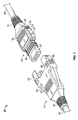
- FIG. 1 shows a perspective view of a plug and a receptacle of a locking low profile PV connector in an unmated position.
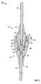
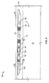
- FIG. 2 shows a side view of the plug and receptacle of FIG. 1 .
- FIG. 3 shows a cross-sectional view of the plug and receptacle in a mated position.
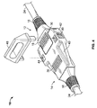
- FIG. 4 shows a perspective view of the mated connector and an extraction tool.
- FIG. 5 shows a perspective view of a plug and a receptacle of a non-locking low profile PV connector in an unmated position.
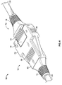
- FIG. 6 shows a perspective view of a plug and a receptacle of the non-locking connector in a mated position.
- FIG. 7 shows a cross-sectional view of the non-locking connector.
- FIG. 8 shows a perspective view of a plug and a receptacle of an alternate embodiment of a low profile PV connector.
- FIG. 9 shows the connector of FIG. 8 in communication with solar arrays.
- An advantage of the present invention is that the low profile PV junction connector allows a PV solar array to be placed in restricted spaces.
- FIGS. 1 , 2 and 3 show a low profile PV (LPPV) connector 10.
- Connector 10 has a plug 12 and a receptacle 14 that are mateable to form an electrical connection.
- Plug 12 includes a strain relief 16, a body 18, locking latches 20, and a male connection 22.
- Strain relief 16 provides a waterproof seal and relieves strain caused by pulling and bending of a cable 24 that extends from plug 12 or receptacle 14.
- Strain relief 16 may be manufactured from a flexible and sturdy material such as Santoprene® rubber, or any other suitable material. Cable 24 conducts power from a solar array 26 (see FIG. 9 ) to plug 12.
- cable 24 may range from a 14 AWG (American Wire Gauge) cable to a 10 AWG cable and may communicate power or data from any source to plug 12 or receptacle 14.
- Plug 12 and receptacle 14 are limited in vertical elevation by the width of cable 24 used with connector 10.
- a five (5) millimeter cable may be used with connector 10.
- any cable may be used with connector 10, including but not limited to, ribbon cable.
- Plug body 18 extends from strain relief 16, and is manufactured from a rigid plastic material or any other suitable material. Plug 12 may be formed by an overmolding process, or any other suitable manufacturing process. Disposed inside plug body 18 is a contact, or blade 28 for facilitating an electrical connection with receptacle 14. Blade 28 may be a faston blade or any other suitable blade or contact. Plug body 18 may also include a grip 30 on the top surface to provide a non-slippery surface for a user to grasp plug 12. Grip 30 may be molded from the same material, or grip 30 may be molded from the same flexible material as strain relief 16. Disposed on both sides of body 18 are locking latches 20. Locking latches 20 extend from plug body 18 and bend at an elbow 32 to extend substantially parallel to body 18. Locking latches 20 have protrusions 34 at the distal end of latch 20. Protrusions 34 engage with receptacle 14 when plug 12 is mated with receptacle 14.
- male connection 22 Extending from body 18 is male connection 22.
- Male connection 22 mateably connects with receptacle 14.
- Sealing ribs 36 are disposed on the outer surface of male connection 22.
- the figures show three sealing ribs 36 disposed on the outer surface of male connection 22. However, any suitable number of sealing ribs 36 may be used.
- Sealing ribs 36 may be formed from a flexible material such as Santoprene® rubber, or any other suitable slightly compressible material.
- sealing ribs 36 When plug 12 is mated with receptacle 14, sealing ribs 36 are compressed against the receptacle to form a seal between plug 12 and receptacle 14. Sealing ribs 36 prevent moisture, dust particles or other matter from entering connector 10.
- Receptacle 14 has a strain relief 16 extending from one end of a receptacle body 40 and a female connection receiver 42 opposite strain relief 16 for receiving plug 12. Strain relief 16 provides waterproof protection and strain relief to a cable 24 that extends from receptacle 14. Cable 24 communicates solar power and energy from a solar array 26 (see FIG. 9 ) to receptacle 14. While a solar array 26 is described, it is appreciated that cable 24 may communicate power or data from other sources and is not limited to solar arrays. Strain relief 16 may be manufactured from a flexible and sturdy material such as Santoprene® rubber, or any other suitable material.
- Receptacle body 40 extends from strain relief 16, and is manufactured from a rigid plastic material or any other suitable material.
- Receptacle 14 may be formed by an overmolding process, or any other suitable manufacturing process.
- Disposed inside receptacle body 40 is a contact, or blade 28 for facilitating an electrical connection with blade 28 in plug 12.
- Blade 28 may be a faston blade or any other suitable blade or contact.
- Receptacle body 40 may also include a grip 30 on the top surface to provide an abrasive surface for a user to grasp receptacle 14.
- Grip 30 may be unitary with receptacle body 40 and molded from the same material, or grip 30 may be molded from the same flexible material as strain relief 16.
- Receiver 42 Extending from receptacle body 40 is receiver 42.
- Receiver 42 is unitary with receptacle body 40 and configured to mate with male connection 22 on plug 12.
- grips 30 Disposed on each side surface of receiver 42 are grips 30 to provide an abrasive surface for a user to grasp receptacle 14.
- Grip 30 may be molded from the same material as receptacle body 40, or grip 30 may be molded from the same flexible material as strain relief 16.
- Apertures 44 are disposed on opposites sides of receiver 42. Apertures 44 are configured and disposed to align with protrusions 34 on locking latches 20 when plug 12 is mated with receptacle 14. Apertures 44 provide access to locking latches 20 when plug 12 is mated with receptacle 14.
- Receiver 42 also includes a ledge 46.
- Ledge 46 engages locking latch 20 when plug 12 is mated with receptacle 14.
- Protrusions 34 engage with ledges 46 and maintain plug 12 engagement with receptacle 14.
- an audible and/or tactile signal may notify the user that plug 12 is secured in receptacle 14.
- an extraction tool may be used to disengage locking latches 20 from ledges 46.
- Extraction tool 48 may be inserted into apertures 44 and contact protrusions 34, to disengage locking latches 20 from ledges 46.
- elbow 32 permits movement of locking latches 20 to disengaged protrusions 34 from ledges 46.
- Plug 12 may be removed from receptacle 14 when extraction tool 48 has disengaged locking latches 20 from ledges 46. Both plug 12 and receptacle 14 of connector 10 are configured not to exceed a maximum height of 8 mm. However, connector 10 may be configured within any suitable height requirement.
- plug 12 may include at least one engaging latch 50.
- Engaging latch 50 extends outward from body 18 of plug 12 and has a projection 52.
- Engaging latch 50 is deformable, as plug 12 is mated with receptacle 14, engaging latch 50 may be displaced inward towards body 18 until projection 52 engages with cavity 54 in receiver 42 in receptacle 14.
- an audible and/or tactile signal may notify the user that plug 12 is secured in receptacle 14.
- plug 12 Once plug 12 is mated with receptacle 14, plug 12 may be removed from receptacle 14 without the aid of a tool or other device.
- a normal force of about 89 Newtons (twenty pounds) or greater may be applied to plug 12, receptacle 14, or both substantially simultaneously to remove plug 12 from receptacle 14.
- Receptacle body 40 of receiver 14 may not include apertures 44 (see, e.g. FIG. 1 ).
- An extraction tool 48 ( FIG. 4 ) or other removal device is unnecessary to remove plug 12 from receptacle 14.
- junction box 54 In another alternate embodiment shown in FIG. 8 , connector 10 is used with a junction box 54.
- Plug 12 is in communication with junction box 54 through cable 24.
- Junction box 54 may be an LPPV junction box, or any other suitable junction box and may include a body 58, strain relief 16, and a solder pad 60.
- An adhesive is used to mount and secure body 58 of junction box 54 to a solar array 26 (see FIG. 9 ) or other suitable device.
- Junction box 54 is disposed on solar array 26 ( FIG. 9 ) such that a conductive foil (not shown) on solar array 26 contacts solder pad 60 on junction box 54. Conductive foil (not shown) is used to provide electrical interconnections between multiple solar arrays 26.
- Conductive foil may be unitary with, or in communication with solar array 26, and extend from solar array 26 to enable a connection with junction box 54 or other suitable connection device.
- Solder pad 60 has a slot 62 for soldering solder pad 60 to a conductive foil (not shown). Once foil (not shown) has been soldered to solder pad 60, an epoxy or other seal or filling (not shown) is applied to solder pad 60. The epoxy (not shown) prevents external objects or elements from damaging solder pad 60 and from damaging the soldered connection between solder pad 60 and foil (not shown).
- Plug 12 may also be a locking plug 12 as described above with reference to FIGS. 1 , 2 , 3 and 4 , above, or plug 12 may be a non-locking plug 12 as described with reference to FIGS. 5 , 6 , and 7 , above.
- Receptacle 64 is mateable with plug 12 and may include a body 66, solder pad 60, and receiver 42. An adhesive is used to mount and secure body 66 of receptacle 64 to a solar array 26 (see FIG. 9 ) or other suitable device. Receptacle 64 is disposed on solar array 26 such that a conductive foil (not shown) on solar array 26 contacts solder pad 60 on receptacle 64. Solder pad 60 has a slot 62 for soldering solder pad 60 to foil (not shown). Once a solder connection has been made between foil (not shown) and solder pad 60, an epoxy or other seal or filling (not shown) is applied to solder pad 60.
- Receiver 42 receives plug 12 and secures plug 12 in receptacle 64.
- Receptacle 64 may be a locking receptacle as described with reference to FIGS. 1 , 2 , 3 , and 4 , above, or receptacle 64 may be a non-locking receptacle as described with reference to FIGS. 5 , 6 and 7 , above.
- FIG. 9 shows connector 10 with junction box 54 mounted and secured to solar array 26.
- Solar arrays 26 are mounted to a roof 70 or other suitable location, where solar arrays 26 may gather solar energy and power.
- Junction box 54 is mounted to a first solar array 26 when body 58 is secured to solar array 26 with an adhesive.
- Receptacle 64 is mounted to a second solar array 26 when body 66 is secured to solar array 26 with an adhesive.
- a small air gap 72 between roof 70 and connector 10 and solar arrays 26 provide space for a user to access solar arrays 26 and/or connector 10 if necessary.
- Connector 10 facilitates communication or power transfer between the first and second solar arrays 26.
- a plurality of connectors 10 may be used to connect a plurality of solar arrays 26.
- FIGS. 1 through 9 Both a locking LPPV connector 10 and a non-locking LPPV connector 10 are shown in FIGS. 1 through 9 . It is appreciated that the locking and non-locking LPPV connectors 10 may be interchanged within applications. It is also appreciated that a locking LPPV connector 10 may be required for certain applications by standards known to those of ordinary skill in the art.
Landscapes
- Details Of Connecting Devices For Male And Female Coupling (AREA)
- Connector Housings Or Holding Contact Members (AREA)
- Coupling Device And Connection With Printed Circuit (AREA)
- Photovoltaic Devices (AREA)
Applications Claiming Priority (1)
| Application Number | Priority Date | Filing Date | Title |
|---|---|---|---|
| US12/144,085 US20090318004A1 (en) | 2008-06-23 | 2008-06-23 | Low profile photovoltaic connector |
Publications (2)
| Publication Number | Publication Date |
|---|---|
| EP2139078A2 true EP2139078A2 (fr) | 2009-12-30 |
| EP2139078A3 EP2139078A3 (fr) | 2011-05-04 |
Family
ID=40791186
Family Applications (1)
| Application Number | Title | Priority Date | Filing Date |
|---|---|---|---|
| EP09162857A Withdrawn EP2139078A3 (fr) | 2008-06-23 | 2009-06-16 | Connecteur bas-profil pour application photovoltaique |
Country Status (5)
| Country | Link |
|---|---|
| US (1) | US20090318004A1 (fr) |
| EP (1) | EP2139078A3 (fr) |
| CN (1) | CN101630796A (fr) |
| CA (1) | CA2668373A1 (fr) |
| MX (1) | MX2009006830A (fr) |
Cited By (2)
| Publication number | Priority date | Publication date | Assignee | Title |
|---|---|---|---|---|
| EP2434587A1 (fr) * | 2010-09-24 | 2012-03-28 | Lapp Engineering & Co. | Dispositif de raccordement pour câbles électriques |
| WO2014072217A1 (fr) * | 2012-11-12 | 2014-05-15 | Multi-Holding Ag | Boîtier de fiche mâle et boîtier de fiche femelle destinés à un connecteur |
Families Citing this family (21)
| Publication number | Priority date | Publication date | Assignee | Title |
|---|---|---|---|---|
| JP2010033836A (ja) * | 2008-07-28 | 2010-02-12 | Fujitsu Ltd | コネクタ及びコネクタ用伝送配線 |
| US7850476B2 (en) * | 2008-10-29 | 2010-12-14 | Tyco Electronics Corporation | Low profile solar laminate connector assembly |
| US20100255724A1 (en) * | 2009-04-03 | 2010-10-07 | Tyco Electronics Corporation | Locking clip for an electrical connector assembly |
| US8038462B2 (en) * | 2010-02-04 | 2011-10-18 | Anderson Power Products, Inc. | Water-tight electrical connector with laterally compressed O-ring |
| US20120085040A1 (en) * | 2010-10-07 | 2012-04-12 | Delphi Technologies, Inc. | Low profile electrical connection system |
| CN202076598U (zh) * | 2011-02-18 | 2011-12-14 | 富士康(昆山)电脑接插件有限公司 | 电连接器组件及其插头连接器 |
| US8408932B2 (en) * | 2011-05-17 | 2013-04-02 | Apple Inc. | Connector with locking mechanisms |
| US8782869B2 (en) * | 2011-05-17 | 2014-07-22 | Apple Inc. | Unlocking tool for male connector |
| US8435063B2 (en) | 2011-06-07 | 2013-05-07 | Phoenix Contact Development & Manufacturing, Inc. | Electrical connector assembly |
| CN102386524A (zh) * | 2011-09-13 | 2012-03-21 | 苏州桑斯达光伏电子有限公司 | 太阳能光伏组件用电连接器 |
| CN102403390A (zh) * | 2011-11-30 | 2012-04-04 | 常熟泓淋连接技术有限公司 | 太阳能光伏组件接线盒 |
| CN102544157A (zh) * | 2012-02-06 | 2012-07-04 | 浙江信达利新能源科技有限公司 | 太阳能光伏接线盒组件 |
| CN103427226A (zh) * | 2012-05-21 | 2013-12-04 | 纬创资通股份有限公司 | 信号线保护装置 |
| US20140035747A1 (en) * | 2012-08-02 | 2014-02-06 | Sennco Solutions Inc. | Dongle, system, and/or method for securing an electronic device |
| DE102012025106A1 (de) * | 2012-12-21 | 2014-06-26 | Erni Production Gmbh & Co. Kg | Elektrischer Steckverbinder |
| US9413110B1 (en) * | 2015-07-08 | 2016-08-09 | Chao-Chieh Liu | Embedded short leaf-spring-equipped crystal head and extractor thereof |
| JP2017208193A (ja) * | 2016-05-17 | 2017-11-24 | 日本圧着端子製造株式会社 | 防水コネクタ |
| CN108631117B (zh) * | 2017-03-23 | 2020-01-31 | 南宁富桂精密工业有限公司 | 自动上锁防盗结构 |
| DE102017125915B4 (de) * | 2017-11-07 | 2026-01-29 | Phoenix Contact Gmbh & Co. Kg | Verriegelung für Steckverbinder |
| CN108649086A (zh) * | 2018-04-23 | 2018-10-12 | 深圳市拓日新能源科技股份有限公司 | 小型双玻组件及建筑幕墙发电系统 |
| CA3250001A1 (fr) * | 2022-04-25 | 2023-11-02 | Affordable Wire Management, Llc | Dispositifs de verrouillage et procédés d’utilisation |
Citations (1)
| Publication number | Priority date | Publication date | Assignee | Title |
|---|---|---|---|---|
| US20090084570A1 (en) | 2007-10-02 | 2009-04-02 | Tyco Electronics Corporation | Low Profile Photovoltaic (LPPV) Box |
Family Cites Families (20)
| Publication number | Priority date | Publication date | Assignee | Title |
|---|---|---|---|---|
| US4310211A (en) * | 1979-12-26 | 1982-01-12 | Amp Incorporated | High current contact system for solar modules |
| GB2244181B (en) * | 1990-04-13 | 1994-12-21 | Oki Electric Cable | Double lock male/female type connector |
| US5382177A (en) * | 1991-11-21 | 1995-01-17 | The Whitaker Corporation | Connector housing with improved latch members |
| EP0650229A3 (fr) * | 1993-10-22 | 1997-01-02 | Amphenol Tuchel Elect | Système de sécurité à sac gonflable. |
| DE19631040A1 (de) * | 1996-08-01 | 1998-02-05 | Bosch Gmbh Robert | Leitungsverbindung zweier elektrischer Leitungen |
| JP3792867B2 (ja) * | 1997-11-06 | 2006-07-05 | キヤノン株式会社 | 太陽電池モジュール、太陽電池アレイ及び太陽光発電装置の施工方法 |
| JPH11159090A (ja) * | 1997-11-27 | 1999-06-15 | Canon Inc | 太陽電池屋根およびその施工方法 |
| JP2000036346A (ja) * | 1998-07-16 | 2000-02-02 | Sumitomo Wiring Syst Ltd | 電気接続用コネクタ |
| JP2000040547A (ja) * | 1998-07-22 | 2000-02-08 | Sumitomo Wiring Syst Ltd | 電気接続用コネクタ |
| DE19921265C2 (de) * | 1999-05-07 | 2001-05-23 | Webasto Vehicle Sys Int Gmbh | Solarmodul zur Anbringung an Fahrzeugen, Verfahren zur Herstellung desselben und seine Verwendung |
| JP3065582U (ja) * | 1999-05-26 | 2000-02-02 | 木谷電器株式会社 | 太陽光発電装置における電力接続用コネクタ |
| US6257920B1 (en) * | 1999-06-25 | 2001-07-10 | Itt Manufacturing Enterprises, Inc. | Cable retention clip |
| JP2001085111A (ja) * | 1999-09-10 | 2001-03-30 | Sumitomo Wiring Syst Ltd | コネクタ |
| DE60039019D1 (de) * | 1999-11-17 | 2008-07-10 | Tyco Electronics Amp Gmbh | Vorrichtung zur Verbindung von Leiterfolien, insbesondere von einem Solarmodul |
| JP4098458B2 (ja) * | 2000-05-10 | 2008-06-11 | 矢崎総業株式会社 | ワイヤハーネスおよびその製造方法 |
| US20040092186A1 (en) * | 2000-11-17 | 2004-05-13 | Patricia Wilson-Nguyen | Textile electronic connection system |
| JP2004014920A (ja) * | 2002-06-10 | 2004-01-15 | Sumitomo Wiring Syst Ltd | ケーブル連結部構造 |
| GB2404094B (en) * | 2003-07-17 | 2008-01-02 | Thales Plc | Electrical connector |
| DE102004012883A1 (de) * | 2004-03-16 | 2005-11-10 | Hirschmann Electronics Gmbh & Co. Kg | Steckverbinder für den elektrischen Anschluss von Solarpanels |
| US7387537B1 (en) * | 2007-01-03 | 2008-06-17 | Tyco Electronics Corporation | Connector system for solar cell roofing tiles |
-
2008
- 2008-06-23 US US12/144,085 patent/US20090318004A1/en not_active Abandoned
-
2009
- 2009-06-09 CA CA002668373A patent/CA2668373A1/fr not_active Abandoned
- 2009-06-16 EP EP09162857A patent/EP2139078A3/fr not_active Withdrawn
- 2009-06-22 MX MX2009006830A patent/MX2009006830A/es not_active Application Discontinuation
- 2009-06-23 CN CN200910166955A patent/CN101630796A/zh active Pending
Patent Citations (1)
| Publication number | Priority date | Publication date | Assignee | Title |
|---|---|---|---|---|
| US20090084570A1 (en) | 2007-10-02 | 2009-04-02 | Tyco Electronics Corporation | Low Profile Photovoltaic (LPPV) Box |
Cited By (3)
| Publication number | Priority date | Publication date | Assignee | Title |
|---|---|---|---|---|
| EP2434587A1 (fr) * | 2010-09-24 | 2012-03-28 | Lapp Engineering & Co. | Dispositif de raccordement pour câbles électriques |
| WO2014072217A1 (fr) * | 2012-11-12 | 2014-05-15 | Multi-Holding Ag | Boîtier de fiche mâle et boîtier de fiche femelle destinés à un connecteur |
| CN104823336A (zh) * | 2012-11-12 | 2015-08-05 | 马尔遆公开股份有限公司 | 插头壳体和用于插接连接器的插座壳体 |
Also Published As
| Publication number | Publication date |
|---|---|
| US20090318004A1 (en) | 2009-12-24 |
| EP2139078A3 (fr) | 2011-05-04 |
| CN101630796A (zh) | 2010-01-20 |
| MX2009006830A (es) | 2010-01-18 |
| CA2668373A1 (fr) | 2009-12-23 |
Similar Documents
| Publication | Publication Date | Title |
|---|---|---|
| US20090318004A1 (en) | Low profile photovoltaic connector | |
| US7850476B2 (en) | Low profile solar laminate connector assembly | |
| EP2115786B1 (fr) | Système connecteur pour tuiles à cellules solaires | |
| US7291036B1 (en) | Photovoltaic connection system | |
| CN101842913B (zh) | 小型光电边缘连接器 | |
| US7824189B1 (en) | Junction box for photovoltaic modules | |
| US8523609B2 (en) | Photovoltaic connector assembly | |
| US7963802B2 (en) | External electrical connectors for solar modules | |
| CN102714248B (zh) | 太阳能模块装置 | |
| EP3314747B1 (fr) | Boîte de jonction solaire | |
| US10224447B2 (en) | Connector and solar cell module comprising the same | |
| CN109863693B (zh) | 太阳能接线盒 | |
| KR102377270B1 (ko) | 전력 전자 기기를 광기전 모듈에 연결하기 위한 장치 및 시스템 | |
| JP2009206416A (ja) | 太陽電池モジュール用端子ボックス | |
| KR102237579B1 (ko) | 창호 일체형 태양광 발전 시스템 및 이의 설치공법 | |
| KR102237578B1 (ko) | 원터치 커넥터 일체형 태양광 모듈용 어셈블리 및 이의 설치 공법 | |
| KR101523048B1 (ko) | 정션박스 | |
| CN107820675A (zh) | 用于太阳能接线盒的端子 | |
| KR101063257B1 (ko) | 터미널단자 | |
| WO2019106602A1 (fr) | Boîte de jonction solaire |
Legal Events
| Date | Code | Title | Description |
|---|---|---|---|
| PUAI | Public reference made under article 153(3) epc to a published international application that has entered the european phase |
Free format text: ORIGINAL CODE: 0009012 |
|
| AK | Designated contracting states |
Kind code of ref document: A2 Designated state(s): AT BE BG CH CY CZ DE DK EE ES FI FR GB GR HR HU IE IS IT LI LT LU LV MC MK MT NL NO PL PT RO SE SI SK TR |
|
| PUAL | Search report despatched |
Free format text: ORIGINAL CODE: 0009013 |
|
| AK | Designated contracting states |
Kind code of ref document: A3 Designated state(s): AT BE BG CH CY CZ DE DK EE ES FI FR GB GR HR HU IE IS IT LI LT LU LV MC MK MT NL NO PL PT RO SE SI SK TR |
|
| STAA | Information on the status of an ep patent application or granted ep patent |
Free format text: STATUS: THE APPLICATION IS DEEMED TO BE WITHDRAWN |
|
| 18D | Application deemed to be withdrawn |
Effective date: 20111105 |