EP2139011A1 - Magnetic core for antenna, method for producing magnetic core for antenna, and antenna - Google Patents
Magnetic core for antenna, method for producing magnetic core for antenna, and antenna Download PDFInfo
- Publication number
- EP2139011A1 EP2139011A1 EP08740203A EP08740203A EP2139011A1 EP 2139011 A1 EP2139011 A1 EP 2139011A1 EP 08740203 A EP08740203 A EP 08740203A EP 08740203 A EP08740203 A EP 08740203A EP 2139011 A1 EP2139011 A1 EP 2139011A1
- Authority
- EP
- European Patent Office
- Prior art keywords
- antenna
- magnetic core
- thin metal
- laminate
- thin
- Prior art date
- Legal status (The legal status is an assumption and is not a legal conclusion. Google has not performed a legal analysis and makes no representation as to the accuracy of the status listed.)
- Granted
Links
Images

Classifications
-
- H—ELECTRICITY
- H01—ELECTRIC ELEMENTS
- H01F—MAGNETS; INDUCTANCES; TRANSFORMERS; SELECTION OF MATERIALS FOR THEIR MAGNETIC PROPERTIES
- H01F41/00—Apparatus or processes specially adapted for manufacturing or assembling magnets, inductances or transformers; Apparatus or processes specially adapted for manufacturing materials characterised by their magnetic properties
- H01F41/02—Apparatus or processes specially adapted for manufacturing or assembling magnets, inductances or transformers; Apparatus or processes specially adapted for manufacturing materials characterised by their magnetic properties for manufacturing cores, coils, or magnets
- H01F41/0206—Manufacturing of magnetic cores by mechanical means
- H01F41/0233—Manufacturing of magnetic circuits made from sheets
-
- H—ELECTRICITY
- H01—ELECTRIC ELEMENTS
- H01F—MAGNETS; INDUCTANCES; TRANSFORMERS; SELECTION OF MATERIALS FOR THEIR MAGNETIC PROPERTIES
- H01F1/00—Magnets or magnetic bodies characterised by the magnetic materials therefor; Selection of materials for their magnetic properties
- H01F1/01—Magnets or magnetic bodies characterised by the magnetic materials therefor; Selection of materials for their magnetic properties of inorganic materials
- H01F1/03—Magnets or magnetic bodies characterised by the magnetic materials therefor; Selection of materials for their magnetic properties of inorganic materials characterised by their coercivity
- H01F1/12—Magnets or magnetic bodies characterised by the magnetic materials therefor; Selection of materials for their magnetic properties of inorganic materials characterised by their coercivity of soft-magnetic materials
- H01F1/14—Magnets or magnetic bodies characterised by the magnetic materials therefor; Selection of materials for their magnetic properties of inorganic materials characterised by their coercivity of soft-magnetic materials metals or alloys
- H01F1/147—Alloys characterised by their composition
- H01F1/153—Amorphous metallic alloys, e.g. glassy metals
- H01F1/15391—Elongated structures, e.g. wires
-
- H—ELECTRICITY
- H01—ELECTRIC ELEMENTS
- H01Q—ANTENNAS, i.e. RADIO AERIALS
- H01Q7/00—Loop antennas with a substantially uniform current distribution around the loop and having a directional radiation pattern in a plane perpendicular to the plane of the loop
- H01Q7/06—Loop antennas with a substantially uniform current distribution around the loop and having a directional radiation pattern in a plane perpendicular to the plane of the loop with core of ferromagnetic material
- H01Q7/08—Ferrite rod or like elongated core
-
- H—ELECTRICITY
- H01—ELECTRIC ELEMENTS
- H01F—MAGNETS; INDUCTANCES; TRANSFORMERS; SELECTION OF MATERIALS FOR THEIR MAGNETIC PROPERTIES
- H01F1/00—Magnets or magnetic bodies characterised by the magnetic materials therefor; Selection of materials for their magnetic properties
- H01F1/01—Magnets or magnetic bodies characterised by the magnetic materials therefor; Selection of materials for their magnetic properties of inorganic materials
- H01F1/03—Magnets or magnetic bodies characterised by the magnetic materials therefor; Selection of materials for their magnetic properties of inorganic materials characterised by their coercivity
- H01F1/12—Magnets or magnetic bodies characterised by the magnetic materials therefor; Selection of materials for their magnetic properties of inorganic materials characterised by their coercivity of soft-magnetic materials
- H01F1/14—Magnets or magnetic bodies characterised by the magnetic materials therefor; Selection of materials for their magnetic properties of inorganic materials characterised by their coercivity of soft-magnetic materials metals or alloys
- H01F1/147—Alloys characterised by their composition
- H01F1/153—Amorphous metallic alloys, e.g. glassy metals
- H01F1/15316—Amorphous metallic alloys, e.g. glassy metals based on Co
-
- H—ELECTRICITY
- H01—ELECTRIC ELEMENTS
- H01F—MAGNETS; INDUCTANCES; TRANSFORMERS; SELECTION OF MATERIALS FOR THEIR MAGNETIC PROPERTIES
- H01F1/00—Magnets or magnetic bodies characterised by the magnetic materials therefor; Selection of materials for their magnetic properties
- H01F1/01—Magnets or magnetic bodies characterised by the magnetic materials therefor; Selection of materials for their magnetic properties of inorganic materials
- H01F1/03—Magnets or magnetic bodies characterised by the magnetic materials therefor; Selection of materials for their magnetic properties of inorganic materials characterised by their coercivity
- H01F1/12—Magnets or magnetic bodies characterised by the magnetic materials therefor; Selection of materials for their magnetic properties of inorganic materials characterised by their coercivity of soft-magnetic materials
- H01F1/14—Magnets or magnetic bodies characterised by the magnetic materials therefor; Selection of materials for their magnetic properties of inorganic materials characterised by their coercivity of soft-magnetic materials metals or alloys
- H01F1/147—Alloys characterised by their composition
- H01F1/153—Amorphous metallic alloys, e.g. glassy metals
- H01F1/15383—Applying coatings thereon
-
- H—ELECTRICITY
- H01—ELECTRIC ELEMENTS
- H01F—MAGNETS; INDUCTANCES; TRANSFORMERS; SELECTION OF MATERIALS FOR THEIR MAGNETIC PROPERTIES
- H01F10/00—Thin magnetic films, e.g. of one-domain structure
- H01F10/08—Thin magnetic films, e.g. of one-domain structure characterised by magnetic layers
- H01F10/10—Thin magnetic films, e.g. of one-domain structure characterised by magnetic layers characterised by the composition
- H01F10/12—Thin magnetic films, e.g. of one-domain structure characterised by magnetic layers characterised by the composition being metals or alloys
- H01F10/13—Amorphous metallic alloys, e.g. glassy metals
- H01F10/138—Amorphous metallic alloys, e.g. glassy metals containing nanocrystallites, e.g. obtained by annealing
-
- H—ELECTRICITY
- H01—ELECTRIC ELEMENTS
- H01F—MAGNETS; INDUCTANCES; TRANSFORMERS; SELECTION OF MATERIALS FOR THEIR MAGNETIC PROPERTIES
- H01F27/00—Details of transformers or inductances, in general
- H01F27/28—Coils; Windings; Conductive connections
- H01F27/32—Insulating of coils, windings, or parts thereof
- H01F27/324—Insulation between coil and core, between different winding sections, around the coil; Other insulation structures
-
- H—ELECTRICITY
- H01—ELECTRIC ELEMENTS
- H01F—MAGNETS; INDUCTANCES; TRANSFORMERS; SELECTION OF MATERIALS FOR THEIR MAGNETIC PROPERTIES
- H01F3/00—Cores, Yokes, or armatures
- H01F3/02—Cores, Yokes, or armatures made from sheets
Definitions
- the present invention relates to a bar-shaped magnetic core for antenna using a laminate of thin metal strips having soft magnetism, and an antenna using the magnetic core for antenna, which is used for a keyless entry system for vehicles and the like.
- antennas having a ferrite core have been used for RFID (wireless IC tag) for a keyless entry system of a vehicle or the like.
- RFID wireless IC tag
- ferrite is brittle, cracks occur therein even due to slight deformation.
- a crack generates by a shock when a key falls to the ground or when a user walks around with the key in a pocket of trousers, etc. so that properties thereof deteriorate.
- an amorphous thin metal strip has been used for a material of the magnetic core for antenna, and the laminated amorphous thin metal strips have been used as the magnetic core.
- patent document 1 discloses a magnetic core for antenna in which an amorphous thin metal strip is wound around a plate bobbin and a coil is wound therearound. It discloses that the end of the magnetic core can thereby have an arbitrary curved surface and thickness, and fluctuation in transmission/reception performance of the magnetic core for antenna can be prevented.
- an object of the present invention is to provide a magnetic core for antenna that can be manufactured in an easy process and has a high Q value (i.e. antenna properties), and to provide a high-performance antenna using the magnetic core for antenna.
- the present invention relates to a method for producing a magnetic core for antenna, wherein thin metal strips are laminate, characterized in that a thin metal band is processed into thin strips having a width of the aimed magnetic core for antenna, that the thin strips are stacked through a resin layer to form a laminate, and subsequently, the laminate is cut to have a length of the aimed magnetic core for antenna.
- magnetic anisotropy is introduced in the magnetic core for antenna in either state of the thin metal band, the thin strip, or the laminate in a width direction thereof, and then cut is performed in the width direction thereof.
- the width direction is a direction along a short side of the magnetic core for antenna. While the width direction may not always be perpendicular to the longitudinal direction, inclination therebetween is preferably within 20° in terms of processability and mechanical strength of products.
- Slit is preferably used as means of processing the continuous thin metal band.
- the processed thin strip preferably has a width of not more than 5 mm.
- a resin layer is preferably formed by applying a polyamic acid solution that is a precursor of a thermosetting polyimide resin, because of its excellent thermal resistance. That can be used for antennas for vehicles in particular.
- the present invention provides a magnetic core for antenna having a rectangular parallelepiped shape and comprising a laminate of thin metal strips, characterized in that projections and depressions of the thin metal strips observed on a long side of a stacking surface are larger than those on a short side of the stacking surface.
- the present invention is also characterized in that parallel machining marks are observed only on the stacking surface along the short side.
- a width of the magnetic core for antenna is not more than 5 mm.
- the magnetic core for antenna preferably has a ratio of a length in relation to a width being not less than 3.
- the thin metal band is preferably manufactured continuously in a band having a thickness of 5 to 100 ⁇ m by the roll quenching method, or manufactured by the roll quenching method and then cut to a length of not less than 50 mm. For example, it has a preferable dimension of not less than 1000 mm 2 in area.
- a thin metal band itself manufactured by the roll quenching method or the laminate of the thin metal strips is subjected to heat treatment in a magnetic field, so that induced magnetic anisotropy is given to all over the thin metal strips.
- the magnetic field in the magnetic heat treatment is applied in the direction to be the short side of the magnetic core for antenna, in other words, the width direction, or the thickness direction. Application of the magnetic field in this direction increases the antenna properties Q.
- the thin metal strips are stacked through an insulating layer made of a material such as a polyimide resin.
- a method for manufacturing the laminate may include heat press bonding.
- the roll press method is preferable since continuous stacking can be attained.
- the magnetic core for antenna is cut out of the laminate only along the width direction of the thin metal strip. Machining of the stacking side surface on the long side will extremely reduce the antenna properties Q of the laminate. As the reason therefor, it is presumed that when the machined surface of the stacking surface becomes larger, machining strain remains and orientation of the given induced magnetic anisotropy becomes uneven, and cutting chippages of the thin metal strip and the resin generated by machining enter between the thin metal strips so that the thin metal strips are conducted and eddy current loss easily increases.
- Heat treatment of the thin metal strip in the magnetic field can induce magnetic anisotropy in the thin metal strip.
- induced magnetic anisotropy is preferably given perpendicular to a magnetic flux generating direction (in the width direction or thickness direction of the thin metal strip). After the induced magnetic anisotropy is given to a continuous thin metal strip or laminate, an endmost part on the short side of the continuous thin metal strips or laminate is preferably cut off. Magnetic anisotropy is not sufficiently given at the endmost part on the short side due to an effect of a demagnetizing field. If the magnetic core for antenna includes the endmost part, the antenna properties decrease.
- a region to be cut is preferably not less than 1 mm from the endmost part, and more preferably not less than 2 mm.
- the end part influenced by the demagnetizing field must be included in the magnetic core for antenna as it is.
- the elongated laminate is heat treated in the magnetic field, and then cut along the width direction thereof so as to have a desired length. Thereby, the magnetic core for antenna can be produced without wasteful cut off portions.
- the present invention is applied to the magnetic core for antenna having a width of not more than 5 mm.
- the demagnetizing field becomes larger as the width is smaller.
- the production method according to the present invention is particularly preferable for producing an antenna having a width of not more than 5 mm which is difficult to give magnetic anisotropy, since the magnetic heat treatment is performed on the thin metal strip or laminate which do not have the end yet formed and then the thin metal strip or laminate is processed.
- the width exceeds 5 mm and a thermosetting resin or the like is used as an adhesive, stacked layers easily peel off.
- the thin metal strip is not more than 30 ⁇ m in thickness.
- the Q value remarkably lowers and sensitivity as an antenna deteriorates, and a level of an output signal lowers, and so on.
- the thin metal strip becomes less practical.
- the thickness of not more than 20 ⁇ m is more preferable, and the thickness of not more than 18 ⁇ m is still more preferable.
- the thin metal strips can be electrically insulated by the resin while they are bonded with a resin.
- a resin polyimide, polyamide imide, epoxy, and the like can be used. From the viewpoint of productivity, it is preferable to apply a liquid resin.
- a method for giving induced magnetic anisotropy for example, heat treatment is performed at a temperature of not more than the Curie temperature while applying a magnetic field.
- a method for performing heat treatment in the magnetic field at a comparatively low temperature of not more than 300°C and not more than the Curie temperature of the material is preferable since embrittlement of the material is reduced and properties thereof are rather improved.
- a relative initial magnetic permeability of the material is not so high, more effect in improvement of the Q value at 100 kHz to 150 kHz is obtained.
- the relative initial magnetic permeability of the material may be selected depending on an application in which the material is used.
- the thin metal strip is an (Fe, Co) SiB-based amorphous strip.
- a CoSiB-based amorphous strip is particularly preferable.
- an FeSiB-based amorphous strip is also preferable because of its enhanced strength.
- a nano crystal thin metal strip such as FeSiCuB, it is necessary to deal with it carefully. In order to produce such a nano crystal thin metal strip, a thin metal strip is heat treated at a temperature of not less than a eutectic temperature, therefore causing embrittlement of the alloy strip.
- an amount “b” of Si is in a range of 1 ⁇ b ⁇ 18, and an amount “c” of B is in a range of 5 ⁇ c ⁇ 15.
- the antenna used for RFID and the like is used at 30 to 200 kHz, and the antenna property Q value useful for the RFID application is obtained unless the amount "b" of Si and the amount “c” of B are respectively within the above ranges.
- the processes includes subsequently, roll quenching, slit processing, applying and drying of a resin, stacking, pressure bonding, and annealing heat treatment.
- the thin metal band is produced by injecting molten alloy heated at a temperature of not less than the melting point (approximately 1000°C to 1500°C in the case of an usual Fe-based material and Co-based material) on a rotating metal cooling roll from a nozzle having a slit (the single rolling method).
- the width of the nozzle slit for injection preferably approximately (a thickness of the strip to be produced) * 0.3 to 0.8 mm. Ceramics such as quartz, silicon nitride and BN are used as a material of the nozzle.
- the thin metal band may be produced using multiple slits.
- a gap between the cooling roll and the nozzle tip is not less than 20 ⁇ m but not more than 500 ⁇ m when the molten alloy is being injected, and is usually not more than 250 ⁇ m.
- the thin metal band is peeled off from the cooling roll at a position of 100 to 1000 mm distant from a position of the roll outer circumference directly under the nozzle slit, measured along a roll outer circumference. Thereby, breakage hardly occurs and a continuous thin metal band having a length not less than 200 m in the longitudinal direction can be produced. Further, by holding a surface temperature of the cooling roll at a temperature of not more than 100 to 250°C, a long thin metal band can be produced with less embrittlement and smaller curvature of the strip in the width direction.
- a metal cooling roll is often water-cooled at a time of mass production.
- Cu and Cu alloys such as Cu-Be, Cu-Zr, and Cu-Cr have great cooling performance and are preferable when producing a wider band.
- an amount of water for cooling the roll is 0.1 to 10 m 3 /min, a thin metal band having little curvature, breakage, embrittlement, or the like can be produced even when an amount of production is as large as not less than 5 kg.
- a preferable amount of water is 0.1 to 1 m 3 /min.
- a diameter of the cooling roll is usually approximately 300 to 1200 mm, and preferably approximately 400 to 1000 mm.
- the diameter thereof is 500 to 800 mm.
- a roll rotational speed is 20 to 40 m/s and an injection pressure is not less than 270 gf/cm 2
- the thin metal band may be produced in inert gas such as He and Ar, if necessary.
- He gas, CO gas, or CO 2 gas is flown near the nozzle during manufacturing, the surface properties of the thin metal band is further improved.
- heated inert gas or nitrogen gas is flown near the nozzle during manufacturing, the surface properties of the thin metal band is also improved.
- slit processing is performed on the thin metal band thus obtained.
- the thin metal band 1 set on an uncoiler is withdrawn, and passed through a one pair slitter provided with a plurality of rotary knives on each of top and bottom slitter. Then, the thin metal band is cut to a size of the magnetic core for antenna to obtain a thin strip 1'. The cut thin strip is taken up on a recoiler.
- a resin solution applied on a thin strip preferably has a thermosetting property.
- Commercially available resins can be used. Usually, the resin is diluted to 5 to 20% by weight with a solvent for use. When a thickness after drying of the solvent is smaller, a space factor improves. However, a rate of occurrence of defects such as pinholes also increases, and insulation between adjacent strips in the laminate may be insufficient. Accordingly, 0.5 to 3 ⁇ m is preferable as the thickness after drying.
- a dip method, a doctor blade method, a gravure roll method or the like can be used as the coating method. The gravure roll method is excellent, in terms of homogeneity of a coating thickness and productivity per time (coating speed). In order to apply the resin on both sides using the gravure roll method, it is necessary to apply the resin on one side at one time.
- a far-infrared heater may be also used for drying.
- a plurality of slit thin strips are withdrawn from the roll, and are continuously stacked with a hot roll.
- the thin strips may be cut to a certain length, stacked, and placed into a mold, and then heat-pressed.
- a commercially available resin film may be sandwiched between the laminate and the movable mold so that the laminate can released from the mold after the pressure bonding in the subsequent step.
- the laminate is heated preferably in a nitrogen atmosphere. A temperature in a furnace is increased to a glass transition point of the coated resin. With holding the temperature, pressure is applied on the thin metal strips to bond them to each other.
- a magnetic field of not less than 200 A/m may be applied, preferably not less than 400 A/m. Any of a direct current magnetic field, an alternating current magnetic field, or a repeated pulsed magnetic field may be used as the magnetic field to be applied. The magnetic field may be applied only in a part of a heat treatment pattern.
- the Fe-based amorphous metal strip having the above-mentioned composition is heat treated at 300 to 400°C
- the Co-based amorphous metal strip is heat treated at 300 to 600°C. Since the material embrittles at this time, defects such as chips and cracks may occur if pressure is applied on the amorphous metal strip laminate during annealing heat treatment. For that reason, annealing is performed preferable without applying load. In order to prevent oxidization of the thin metal strip surface, the same atmosphere as that in the pressure bonding process is preferable. Heat treatment time of 0.1 to 20 hours is preferable.
- An atmosphere in a heat treating furnace may be inert gas such as argon or nitrogen gas, in a vacuum or in air depending on the case.
- temperature distribution of the magnetic core during heat treatment is controlled within 10°C.
- An average heating rate is preferably 0.3 to 100°C/min for not less than 0.5 hours, and an average cooling rate is preferably 0.3 to 300°C/min.
- the heating rate of 1 to 20°C/min, a maximum temperature of 300 to 370°C for 1 to 3 hours are further preferable.
- the same effect is also obtained by two-stage heat treatment, by heat treatment for a long time at low temperature of not more than 250°C, or the like.
- the range of 320 to 350°C is preferably set in a part of a heat treatment pattern for approximately 0.2 to 1 hour.
- a heat treatment pattern is preferable such that the magnetic core is once maintained at a temperature lower than a target temperature, then heated and maintained at the target temperature and cooled at the cooling rate of 0.3 to 5°C/min.
- heat treatment is usually performed in an inert gas atmosphere at a dew point of not more than -30°C.
- the present invention it is possible to provide a magnetic core for antenna having a high Q value (namely, antenna properties) and a high-performance antenna using the magnetic core for antenna with a simple production method.
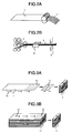
- Fig. 1 shows a laminate 3 obtained by heat treating a thin metal strip 1 in a magnetic field, and stacking the thin metal strips 1 through an insulating layer 2.
- a longitudinal (traverse) direction in Fig. 1 is a longitudinal direction of a thin strip obtained by slitting the thin metal band produced with a hyperquenching roll.
- a magnetic field is applied in a direction perpendicularly to the longitudinal direction, and reference numeral 4 denotes a direction of induced magnetic anisotropy.
- the thin metal strip 1 is coated with a polyamic acid solution, which is a precursor of a polyimide resin, and pressure bonded by roll pressing.
- a polyamic acid solution which is a precursor of a polyimide resin
- the laminate is cut along a cutout line 5 only along a width direction (short side direction) so that the cut laminate may have a long side in the longitudinal direction thereof.
- Order of the stacking process and annealing heat treatment process can be changed depending on a temperature of each process, and continuous processing is possible. For that reason, the manufacturing method is flexible and also has the advantage of reduction of manufacturing cost.
- Figs. 3A and 3B are diagrams showing a process for producing a magnetic core for antenna in the prior art.
- the thin metal band 1 is cut along a cutout line 15 in a direction perpendicularly to a direction 14 of induced magnetic anisotropy applied in the longitudinal direction, and a plurality of metal thin pieces 6 are obtained.
- the plurality of metal thin pieces 6 are stacked through a resin layer, and a magnetic core 7 for an antenna is obtained.
- the thin metal bands 1 are stacked through a resin layer, and a laminate 3' to which induced magnetic anisotropy is given in the longitudinal direction is obtained.
- the laminate 3' is cut along the cutout line 15 in the direction perpendicularly to the direction 14 of induced magnetic anisotropy, and a magnetic core 7 for an antenna is obtained.
- Chippages of the thin metal strip 1 generated in cutting adhere to the insulating layer 2 interposed between the thin metal strips 1. Since the scraps have conductivity, the chippages electrically form a short-circuit between the thin metal strips 1 across the interposed insulating layer 2. This is because a thickness of the insulating layer 2 is as thin as approximately 1 ⁇ m while a thickness of the thin metal strip 1 is usually approximately 15 to 25 ⁇ m. As a result, the thin metal strips 1 are apparently integrated although locally, and a thickness thereof increases.
- strain is induced in the strip by cutting, so that magnetic properties deteriorate.
- the antenna property Q value improves if the laminate 3 is immersed in an etching solution to remove the scraps after cut, or if a process for remove a cutting surface containing strain is employed.
- the etching process causes increase of cost, and further, reliability may deteriorate due to the residual etching solution.
- the thin metal strips are stacked, and subsequently the laminate is cut only along the width direction which is to be the short side of the magnetic core for antenna after stacked, in order to suppress the influences. This suppresses the above-mentioned influences as much as possible.
- An amorphous magnetic band of an alloy represented by CO bal. Fe 1.3 Mn 3.7 Mo 2.5 Si 14.6 B 9.5 (atomic %) and having a width of 20 mm and a thickness of 15 ⁇ m was produced continuously.
- the amorphous magnetic alloy band was subjected to slit processing in the longitudinal direction of the band, and a thin strip having a width of 2 mm was obtained. By winding the thin strip in a rolled form, a strip roll was produced. Then, as shown in Fig. 2B , a laminate was produced by simultaneously withdrawing the thin strips from a plurality of strip rolls.
- a polyamic acid solution that is a precursor of a thermosetting polyimide resin was applied in 10 -3 kg/m 2 (not shown).
- a total of 23 sheets of thin strips coated with the resin were heated at 360°C by roll pressing 10 having a feed-speed of 300 mm/min to produce a long laminate having a width of 2 mm and 23 layers.
- the long laminate after roll pressing was subjected to annealing in order to cure the polyimide resin and remove distortion in the strips generated during the roll pressing.
- the long laminate was passed through a magnetic field generator 8, and a magnetic field of 320 kA/m was applied to the strip in the width direction thereof.
- the long laminate was temporarily cut by a cutting device 9 to have a length of 1 m. Then, the long laminate was cut with a revolving diamond cutter along the width direction of the strip to produce a magnetic core for antenna having a width of 2 mm, a length of 18 mm, and 23 stacked layers. On a stacking surface in a width direction of the magnetic core for antenna, a cutting trace caused by the diamond cutter was observed. While the displacement of the strips on the stacking surface in a longitudinal direction was not less than 0.5 ⁇ m, that in the width direction (short side direction) was not less than 0.5 ⁇ m.
- Comparative Example 1 is a sample in a case where production was made in the same manner as Example 1 except that no magnetic field was applied.
- Comparative Example 2 is a sample in a case where the thin metal band was subjected to slit processing to have a dimension (18 mm) in the longitudinal direction of the magnetic core for antenna, and then the thin metal strips were stacked, and the obtained laminate was cut in the longitudinal direction so as to have a width of 2 mm.
- Comparative Example 3 is a sample in a case where the thin metal strips were stacked to produce a laminate, and then the obtained laminate was cut both in the longitudinal direction and in the width direction (short side direction) to produce a magnetic core for antenna.
- Comparative Example 4 is a sample in a case where the laminate was cut in the longitudinal direction and then etched. Table 1 shows that the example 1 without etching according to the present invention can obtain the Q value as comparable with that of Comparative Example 4 (etching is essential).
- An antenna was produced using the magnetic core for antenna of in Example 1.
- An enamel-coated copper wire having a diameter of 0.07 mm and insulated was wound around the magnetic core for antenna for 1200 turns.
- a magnetic field having a frequency of 40 kHz and a magnetic field strength of 14 pT was applied to the antenna from the outside as an effective value of an alternating current magnetic field corresponding to a magnetic field component of an electromagnetic wave. Then, an output voltage was measured.
- Table 2 shows results. Table 2 shows that an output voltage comparable with that of Comparative Example 4 is obtained.
- An amorphous magnetic alloy band represented by Co bal. Fe 1.3 Mn 3 , 7 Mo 2.5 Si 14.6 B 9.5 (atomic %) and having a width of 20 mm and a thickness of 15 ⁇ m was produced continuously.
- the amorphous magnetic alloy band was subjected to slit processing in a longitudinal direction of the strip, and a thin strip having a width of 2 mm was obtained.
- the thin strip was continuously passed through a heat treating furnace, and simultaneously, a magnetic field of 320 kA/m was applied to the thin strip in the width direction thereof.
- a polyamic acid solution, that is a precursor of a thermosetting polyimide resin, was applied, in 10 -3 kg/m 2 , to the thus-obtained thin strip having magnetic anisotropy.
- An amorphous magnetic alloy band represented by Co bal. Fe i.3 Mn 3.7 Mo 2.5 Si 14.6 B 9.5 (atomic %) and having a width of 20 mm and a thickness of 15 ⁇ m was produced continuously.
- This amorphous magnetic alloy strip was continuously passed through a heat treating furnace, and simultaneously, a magnetic field of 320 kA/m was applied to the amorphous magnetic alloy strip in the thickness direction thereof.
- Thus-obtained amorphous magnetic alloy band having magnetic anisotropy was subjected to slit processing in the longitudinal direction thereof, and a thin strip having a width of 2 mm was obtained.
- a polyamic acid solution that is a precursor of a thermosetting polyimide resin was applied in 10 -3 kg/m 2 , to the thin strip. Then, 23 sheets of the thin strips coated with the resin were prepared. Subsequently, the 23 sheets of thin strips were heated at 360°C by roll pressing having a feed-speed of 300 mm/min to produce a long laminate having a width of 2 mm and 23 layers. Then, the long laminate was cut by a revolving diamond cutter in the width direction thereof to produce a magnetic core for antenna having a width of 2 mm, a length of 18 mm, and 23 stacked layers.
- the amorphous magnetic alloy strips each having a width of 3 mm, 4.5 mm, 6 mm and 10 mm were prepared. Under the same conditions as those in Example 1 except for the width, 250 of the magnetic cores for an antenna were produced for each width mentioned above. Out of the magnetic cores for an antenna, defective items in which peeling off occurred between stacked layers of the strips of the magnetic core for antenna were discriminated by inspection, and yield rate was examined. Table 3 shows the result. When the width of the strip exceeds 5 mm, the yield rate suddenly deteriorates. As for a cause of such peeling off, it is presumed that the thermosetting polyimide resin used as the adhesive layer generates gas when drying or heating during heat treatment in a magnetic field, and the gas did not escape from the side surface of the laminate.
- the antenna according to the present invention can be used for a radio wave receiving antenna used for radio-controlled clocks, and keyless entry systems for automobiles, residences etc., and a RFID tag system. Particularly, since the antenna according to the present invention can be miniaturized, the antenna according to the present invention has possibility of launching a new ubiquitous era.
Landscapes
- Engineering & Computer Science (AREA)
- Power Engineering (AREA)
- Manufacturing & Machinery (AREA)
- Physics & Mathematics (AREA)
- Electromagnetism (AREA)
- Chemical & Material Sciences (AREA)
- Dispersion Chemistry (AREA)
- Manufacturing Cores, Coils, And Magnets (AREA)
- Soft Magnetic Materials (AREA)
Abstract
Description
- The present invention relates to a bar-shaped magnetic core for antenna using a laminate of thin metal strips having soft magnetism, and an antenna using the magnetic core for antenna, which is used for a keyless entry system for vehicles and the like.
- Conventionally, antennas having a ferrite core have been used for RFID (wireless IC tag) for a keyless entry system of a vehicle or the like.
However, since ferrite is brittle, cracks occur therein even due to slight deformation. Thus, a crack generates by a shock when a key falls to the ground or when a user walks around with the key in a pocket of trousers, etc. so that properties thereof deteriorate. In order to solve the problem, an amorphous thin metal strip has been used for a material of the magnetic core for antenna, and the laminated amorphous thin metal strips have been used as the magnetic core.
For example,patent document 1 discloses a magnetic core for antenna in which an amorphous thin metal strip is wound around a plate bobbin and a coil is wound therearound. It discloses that the end of the magnetic core can thereby have an arbitrary curved surface and thickness, and fluctuation in transmission/reception performance of the magnetic core for antenna can be prevented. - Further decrease in thickness and higher magnetic properties (low loss, high magnetic permeability, and high magnetic flux density) are demanded of the magnetic core for antenna for the RFID in recent years. For that reason, development of a magnetic core formed of laminated thin metal strips as disclosed in
patent document 2 has been made, as well as the antennas having the thick core material as mentioned above. Such a magnetic core is obtained by stacking and integrating thin metal strips having high magnetic properties, such as amorphous or nano crystal thin metal strips.
An adhesive such as a resin is applied on a surface of the thin metal strip, and subsequently, the thin metal strips are pressure bonded using a hot press, etc. These techniques have been also disclosed inpatent document 3, etc. -
- PATENT DOCUMENT 1:
JP-A-2004-166071 - PATENT DOCUMENT 2:
JP-A-07-278763 - PATENT DOCUMENT 3:
WO2003/060175 - However, in manufacturing an antenna having an elongated shape using a magnetic core made of such an amorphous soft magnetic strip material, there is a problem that a sufficient Q value is not obtained. The Q value is defined by Q = ωL/R, where ω = 2πf, L: inductance, and R: resistance including loss of a coil.
Further, a strip has been conventionally cut and subsequently stacked. In this method, however, small sized soft magnetic strips must be stacked, and thus working efficiency is very low. In order to improve the working efficiency, soft magnetic strips having a certain dimension are desirably stacked, and then, processed into a desired antenna shape.
Accordingly, an object of the present invention is to provide a magnetic core for antenna that can be manufactured in an easy process and has a high Q value (i.e. antenna properties), and to provide a high-performance antenna using the magnetic core for antenna. - The present invention relates to a method for producing a magnetic core for antenna, wherein thin metal strips are laminate, characterized in that a thin metal band is processed into thin strips having a width of the aimed magnetic core for antenna, that the thin strips are stacked through a resin layer to form a laminate, and subsequently, the laminate is cut to have a length of the aimed magnetic core for antenna.
Preferably, magnetic anisotropy is introduced in the magnetic core for antenna in either state of the thin metal band, the thin strip, or the laminate in a width direction thereof, and then cut is performed in the width direction thereof.
Here, the width direction is a direction along a short side of the magnetic core for antenna. While the width direction may not always be perpendicular to the longitudinal direction, inclination therebetween is preferably within 20° in terms of processability and mechanical strength of products. - Slit is preferably used as means of processing the continuous thin metal band. Moreover, the processed thin strip preferably has a width of not more than 5 mm.
- A resin layer is preferably formed by applying a polyamic acid solution that is a precursor of a thermosetting polyimide resin, because of its excellent thermal resistance. That can be used for antennas for vehicles in particular.
- The present invention provides a magnetic core for antenna having a rectangular parallelepiped shape and comprising a laminate of thin metal strips, characterized in that projections and depressions of the thin metal strips observed on a long side of a stacking surface are larger than those on a short side of the stacking surface. The present invention is also characterized in that parallel machining marks are observed only on the stacking surface along the short side.
- Preferably, a width of the magnetic core for antenna is not more than 5 mm. Moreover, the magnetic core for antenna preferably has a ratio of a length in relation to a width being not less than 3.
- The thin metal band is preferably manufactured continuously in a band having a thickness of 5 to 100 µm by the roll quenching method, or manufactured by the roll quenching method and then cut to a length of not less than 50 mm. For example, it has a preferable dimension of not less than 1000 mm2 in area.
- In the magnetic core for antenna including a laminate of the thin metal strips, eddy current loss decreases and a Q value improves. According to the present invention, a thin metal band itself manufactured by the roll quenching method or the laminate of the thin metal strips is subjected to heat treatment in a magnetic field, so that induced magnetic anisotropy is given to all over the thin metal strips. The magnetic field in the magnetic heat treatment is applied in the direction to be the short side of the magnetic core for antenna, in other words, the width direction, or the thickness direction. Application of the magnetic field in this direction increases the antenna properties Q.
- The thin metal strips are stacked through an insulating layer made of a material such as a polyimide resin. A method for manufacturing the laminate may include heat press bonding. The roll press method is preferable since continuous stacking can be attained. The magnetic core for antenna is cut out of the laminate only along the width direction of the thin metal strip. Machining of the stacking side surface on the long side will extremely reduce the antenna properties Q of the laminate. As the reason therefor, it is presumed that when the machined surface of the stacking surface becomes larger, machining strain remains and orientation of the given induced magnetic anisotropy becomes uneven, and cutting chippages of the thin metal strip and the resin generated by machining enter between the thin metal strips so that the thin metal strips are conducted and eddy current loss easily increases.
- Heat treatment of the thin metal strip in the magnetic field can induce magnetic anisotropy in the thin metal strip. In order to improve the antenna properties Q, induced magnetic anisotropy is preferably given perpendicular to a magnetic flux generating direction (in the width direction or thickness direction of the thin metal strip).
After the induced magnetic anisotropy is given to a continuous thin metal strip or laminate, an endmost part on the short side of the continuous thin metal strips or laminate is preferably cut off. Magnetic anisotropy is not sufficiently given at the endmost part on the short side due to an effect of a demagnetizing field. If the magnetic core for antenna includes the endmost part, the antenna properties decrease. A region to be cut is preferably not less than 1 mm from the endmost part, and more preferably not less than 2 mm.
When the magnetic heat treatment is performed after processing the laminate into the size of the magnetic core for antenna in a width and a length direction, the end part influenced by the demagnetizing field must be included in the magnetic core for antenna as it is. In order to avoid that, it is necessary to perform the magnetic heat treatment on a laminate that is at least longer than the length of the magnetic core for antenna, and then process the laminate to the length of the aimed magnetic core for antenna in the width direction of the laminate. Preferably, the elongated laminate is heat treated in the magnetic field, and then cut along the width direction thereof so as to have a desired length. Thereby, the magnetic core for antenna can be produced without wasteful cut off portions. - Preferably, the present invention is applied to the magnetic core for antenna having a width of not more than 5 mm. As described above, when the magnetic field is applied, the demagnetizing field becomes larger as the width is smaller. For that reason, the production method according to the present invention is particularly preferable for producing an antenna having a width of not more than 5 mm which is difficult to give magnetic anisotropy, since the magnetic heat treatment is performed on the thin metal strip or laminate which do not have the end yet formed and then the thin metal strip or laminate is processed.
When the width exceeds 5 mm and a thermosetting resin or the like is used as an adhesive, stacked layers easily peel off. This is because a gas is generated from the resin when heat is applied thereto during drying process, or the magnetic heat treatment, etc., and an adhesion surface of the stacked layers becomes smaller due to the gas. When the width is not more than 5 mm, such a problem of peeling off reduces since the generated gas escapes from the side surface of the laminate. - Preferably, the thin metal strip is not more than 30 µm in thickness. When the thickness exceeds 30 µm, the Q value remarkably lowers and sensitivity as an antenna deteriorates, and a level of an output signal lowers, and so on. Thus, the thin metal strip becomes less practical. The thickness of not more than 20 µm is more preferable, and the thickness of not more than 18 µm is still more preferable.
- The thin metal strips can be electrically insulated by the resin while they are bonded with a resin. As the resin, polyimide, polyamide imide, epoxy, and the like can be used. From the viewpoint of productivity, it is preferable to apply a liquid resin.
- As for a method for giving induced magnetic anisotropy, for example, heat treatment is performed at a temperature of not more than the Curie temperature while applying a magnetic field. For an antenna, a method for performing heat treatment in the magnetic field at a comparatively low temperature of not more than 300°C and not more than the Curie temperature of the material is preferable since embrittlement of the material is reduced and properties thereof are rather improved. When a relative initial magnetic permeability of the material is not so high, more effect in improvement of the Q value at 100 kHz to 150 kHz is obtained. The relative initial magnetic permeability of the material may be selected depending on an application in which the material is used.
- Preferably, the thin metal strip is an (Fe, Co) SiB-based amorphous strip. When the antenna properties have priority, a CoSiB-based amorphous strip is particularly preferable. For the antenna, an FeSiB-based amorphous strip is also preferable because of its enhanced strength.
As for a nano crystal thin metal strip, such as FeSiCuB, it is necessary to deal with it carefully. In order to produce such a nano crystal thin metal strip, a thin metal strip is heat treated at a temperature of not less than a eutectic temperature, therefore causing embrittlement of the alloy strip. - A CoSiB-based thin metal strip represented by a general formula: (Co1-aFea)100-b-c-dSibBcMd (in atomic %, where, M denotes at least a kind of element selected from Cr, Mn, Ti, Zr, Mo, W, Ni, Hf, Nb, Ta, and Cu, and "a", "b", "c" and "d" respectively satisfy 0 ≤ a ≤ 0.2, 1 ≤ b ≤ 18, 5 ≤ c ≤ 15, and 0 ≤ d ≤ 20) is preferably. Inevitable impurities may be also included as long as a total amount thereof are not more than 1% (in atomic %). "M" of the alloy composition of the strip has effect of improving the antenna property Q value and corrosion resistance.
- When a content ratio "a" of Fe exceeds 0.2, magnetostriction increases and the Q value easily lowers due to deformation and adhesion of the resin, etc. Preferably, an amount "b" of Si is in a range of 1 ≤ b ≤ 18, and an amount "c" of B is in a range of 5 ≤ c ≤ 15. The antenna used for RFID and the like is used at 30 to 200 kHz, and the antenna property Q value useful for the RFID application is obtained unless the amount "b" of Si and the amount "c" of B are respectively within the above ranges.
- Next, an embodiment of a method for producing a magnetic core for antenna according to the present invention will be described in detail in the order of processes. The processes includes subsequently, roll quenching, slit processing, applying and drying of a resin, stacking, pressure bonding, and annealing heat treatment.
- The thin metal band is produced by injecting molten alloy heated at a temperature of not less than the melting point (approximately 1000°C to 1500°C in the case of an usual Fe-based material and Co-based material) on a rotating metal cooling roll from a nozzle having a slit (the single rolling method).
The width of the nozzle slit for injection preferably approximately (a thickness of the strip to be produced) * 0.3 to 0.8 mm. Ceramics such as quartz, silicon nitride and BN are used as a material of the nozzle. The thin metal band may be produced using multiple slits. In the single rolling method, a gap between the cooling roll and the nozzle tip is not less than 20 µm but not more than 500 µm when the molten alloy is being injected, and is usually not more than 250 µm.
In particular, the thin metal band is peeled off from the cooling roll at a position of 100 to 1000 mm distant from a position of the roll outer circumference directly under the nozzle slit, measured along a roll outer circumference. Thereby, breakage hardly occurs and a continuous thin metal band having a length not less than 200 m in the longitudinal direction can be produced. Further, by holding a surface temperature of the cooling roll at a temperature of not more than 100 to 250°C, a long thin metal band can be produced with less embrittlement and smaller curvature of the strip in the width direction. - A metal cooling roll is often water-cooled at a time of mass production. As the material of the cooling roll, Cu and Cu alloys such as Cu-Be, Cu-Zr, and Cu-Cr have great cooling performance and are preferable when producing a wider band. Particularly, when an amount of water for cooling the roll is 0.1 to 10 m3/min, a thin metal band having little curvature, breakage, embrittlement, or the like can be produced even when an amount of production is as large as not less than 5 kg.
Particularly when a very thin strip is produced, a preferable amount of water is 0.1 to 1 m3/min. A diameter of the cooling roll is usually approximately 300 to 1200 mm, and preferably approximately 400 to 1000 mm. Particularly desirably, the diameter thereof is 500 to 800 mm.
Moreover, when a roll rotational speed is 20 to 40 m/s and an injection pressure is not less than 270 gf/cm2, a thin metal band with satisfactory surface properties can be produced. The thin metal band may be produced in inert gas such as He and Ar, if necessary.
In addition, when He gas, CO gas, or CO2 gas is flown near the nozzle during manufacturing, the surface properties of the thin metal band is further improved. Moreover, when heated inert gas or nitrogen gas is flown near the nozzle during manufacturing, the surface properties of the thin metal band is also improved. - As shown in
Fig. 2A , slit processing is performed on the thin metal band thus obtained. Thethin metal band 1 set on an uncoiler is withdrawn, and passed through a one pair slitter provided with a plurality of rotary knives on each of top and bottom slitter. Then, the thin metal band is cut to a size of the magnetic core for antenna to obtain a thin strip 1'. The cut thin strip is taken up on a recoiler. - A resin solution applied on a thin strip preferably has a thermosetting property. Commercially available resins can be used. Usually, the resin is diluted to 5 to 20% by weight with a solvent for use. When a thickness after drying of the solvent is smaller, a space factor improves. However, a rate of occurrence of defects such as pinholes also increases, and insulation between adjacent strips in the laminate may be insufficient. Accordingly, 0.5 to 3 µm is preferable as the thickness after drying.
When the resin is applied on both sides of the thin metal strip, sufficient bonding strength between the resin and the metal is obtained in the steps after drying and thereafter. A dip method, a doctor blade method, a gravure roll method or the like can be used as the coating method. The gravure roll method is excellent, in terms of homogeneity of a coating thickness and productivity per time (coating speed). In order to apply the resin on both sides using the gravure roll method, it is necessary to apply the resin on one side at one time. - In order to dry the resin, it is preferable to increase an amount of wind within a drying furnace. A far-infrared heater may be also used for drying.
- A plurality of slit thin strips are withdrawn from the roll, and are continuously stacked with a hot roll. Alternatively, the thin strips may be cut to a certain length, stacked, and placed into a mold, and then heat-pressed. In this case, since a movable mold for applying pressure contacts the top and bottom strips in the laminate, a commercially available resin film may be sandwiched between the laminate and the movable mold so that the laminate can released from the mold after the pressure bonding in the subsequent step.
The laminate is heated preferably in a nitrogen atmosphere. A temperature in a furnace is increased to a glass transition point of the coated resin. With holding the temperature, pressure is applied on the thin metal strips to bond them to each other. An upper limit of the temperature is less than the thermal decomposition starting temperature of the resin.
Preferably, the applied pressure is not less than 1 MPa since the resin solution sufficiently match the adjacent resin film or the thin metal strip surface. When the pressure exceeds 70 MPa, adjacent thin metal strips may contact each other. However, when conditions such as a drying atmosphere match, the applied pressure is not always necessary, and the laminate can be produced only by stacking.
Anisotropy can be induced in the laminate by heat treating the laminate at a temperature of not more than the Curie temperature while applying a magnetic field to the laminate in the width direction thereof. The process to give anisotropy may be performed in a state of the thin metal band or in a state of the thin strip. A magnetic field of not less than 200 A/m may be applied, preferably not less than 400 A/m. Any of a direct current magnetic field, an alternating current magnetic field, or a repeated pulsed magnetic field may be used as the magnetic field to be applied. The magnetic field may be applied only in a part of a heat treatment pattern. - When an amorphous thin metal strip is annealed, magnetic properties can be further improved. Preferably, the Fe-based amorphous metal strip having the above-mentioned composition is heat treated at 300 to 400°C, and the Co-based amorphous metal strip is heat treated at 300 to 600°C. Since the material embrittles at this time, defects such as chips and cracks may occur if pressure is applied on the amorphous metal strip laminate during annealing heat treatment.
For that reason, annealing is performed preferable without applying load. In order to prevent oxidization of the thin metal strip surface, the same atmosphere as that in the pressure bonding process is preferable. Heat treatment time of 0.1 to 20 hours is preferable. - An atmosphere in a heat treating furnace may be inert gas such as argon or nitrogen gas, in a vacuum or in air depending on the case. Preferably, temperature distribution of the magnetic core during heat treatment is controlled within 10°C. An average heating rate is preferably 0.3 to 100°C/min for not less than 0.5 hours, and an average cooling rate is preferably 0.3 to 300°C/min. The heating rate of 1 to 20°C/min, a maximum temperature of 300 to 370°C for 1 to 3 hours are further preferable.
The same effect is also obtained by two-stage heat treatment, by heat treatment for a long time at low temperature of not more than 250°C, or the like. Even in the case of low-temperature heat treatment, the range of 320 to 350°C is preferably set in a part of a heat treatment pattern for approximately 0.2 to 1 hour.
When a dimension of the magnetic core is large and a heat capacity of the magnetic core is large, or when a large number of magnetic cores are heat treated at once, it is important to control the temperature distribution of the magnetic core within 10°C. As the means, a heat treatment pattern is preferable such that the magnetic core is once maintained at a temperature lower than a target temperature, then heated and maintained at the target temperature and cooled at the cooling rate of 0.3 to 5°C/min.
Desirably, heat treatment is usually performed in an inert gas atmosphere at a dew point of not more than -30°C. When heat treatment is performed in an inert gas atmosphere whose dew point is not higher than -60°C, fluctuation is further reduced. - According to the present invention, it is possible to provide a magnetic core for antenna having a high Q value (namely, antenna properties) and a high-performance antenna using the magnetic core for antenna with a simple production method.
- Hereinafter, a method for producing a magnetic core for antenna according to the present invention will be described referring to
Figs. 1 ,2A and 2B .
Fig. 1 shows alaminate 3 obtained by heat treating athin metal strip 1 in a magnetic field, and stacking thethin metal strips 1 through an insulatinglayer 2. A longitudinal (traverse) direction inFig. 1 is a longitudinal direction of a thin strip obtained by slitting the thin metal band produced with a hyperquenching roll. A magnetic field is applied in a direction perpendicularly to the longitudinal direction, andreference numeral 4 denotes a direction of induced magnetic anisotropy. In stacking, for example, thethin metal strip 1 is coated with a polyamic acid solution, which is a precursor of a polyimide resin, and pressure bonded by roll pressing. Thereby, the stacking process can be performed in a roll to roll (Roll-to-Roll) process, and thus continuous manufacturing is possible. The laminate is cut along acutout line 5 only along a width direction (short side direction) so that the cut laminate may have a long side in the longitudinal direction thereof. Order of the stacking process and annealing heat treatment process can be changed depending on a temperature of each process, and continuous processing is possible. For that reason, the manufacturing method is flexible and also has the advantage of reduction of manufacturing cost. -
Figs. 3A and 3B are diagrams showing a process for producing a magnetic core for antenna in the prior art.
InFig. 3A , thethin metal band 1 is cut along acutout line 15 in a direction perpendicularly to adirection 14 of induced magnetic anisotropy applied in the longitudinal direction, and a plurality of metal thin pieces 6 are obtained. Subsequently, the plurality of metal thin pieces 6 are stacked through a resin layer, and amagnetic core 7 for an antenna is obtained.
InFig. 3B , thethin metal bands 1 are stacked through a resin layer, and a laminate 3' to which induced magnetic anisotropy is given in the longitudinal direction is obtained. The laminate 3' is cut along thecutout line 15 in the direction perpendicularly to thedirection 14 of induced magnetic anisotropy, and amagnetic core 7 for an antenna is obtained.
Chippages of thethin metal strip 1 generated in cutting adhere to the insulatinglayer 2 interposed between the thin metal strips 1. Since the scraps have conductivity, the chippages electrically form a short-circuit between thethin metal strips 1 across the interposed insulatinglayer 2. This is because a thickness of the insulatinglayer 2 is as thin as approximately 1 µm while a thickness of thethin metal strip 1 is usually approximately 15 to 25 µm.
As a result, thethin metal strips 1 are apparently integrated although locally, and a thickness thereof increases. Increase of the thickness leads to increase of eddy current loss when alternating voltage is applied to the product used as a magnetic core for antenna. Increase of the eddy current loss leads to increase of a resistance component R, remarkably reducing the Q value (= ωL/R).
In addition, strain is induced in the strip by cutting, so that magnetic properties deteriorate.
The antenna property Q value improves if thelaminate 3 is immersed in an etching solution to remove the scraps after cut, or if a process for remove a cutting surface containing strain is employed.
However, the etching process causes increase of cost, and further, reliability may deteriorate due to the residual etching solution.
Accordingly, in the present invention, the thin metal strips are stacked, and subsequently the laminate is cut only along the width direction which is to be the short side of the magnetic core for antenna after stacked, in order to suppress the influences. This suppresses the above-mentioned influences as much as possible. - Next, the present invention will be described in detail with Examples, which do not limit the present invention.
- An amorphous magnetic band of an alloy represented by CObal.Fe1.3Mn3.7Mo2.5Si14.6B9.5 (atomic %) and having a width of 20 mm and a thickness of 15 µm was produced continuously. As shown in
Fig. 2A , the amorphous magnetic alloy band was subjected to slit processing in the longitudinal direction of the band, and a thin strip having a width of 2 mm was obtained.
By winding the thin strip in a rolled form, a strip roll was produced. Then, as shown inFig. 2B , a laminate was produced by simultaneously withdrawing the thin strips from a plurality of strip rolls. While the thin strips were withdrawn, a polyamic acid solution that is a precursor of a thermosetting polyimide resin was applied in 10-3 kg/m2 (not shown). A total of 23 sheets of thin strips coated with the resin were heated at 360°C by roll pressing 10 having a feed-speed of 300 mm/min to produce a long laminate having a width of 2 mm and 23 layers.
The long laminate after roll pressing was subjected to annealing in order to cure the polyimide resin and remove distortion in the strips generated during the roll pressing. Moreover, in order to induce magnetic anisotropy in the strip, the long laminate was passed through amagnetic field generator 8, and a magnetic field of 320 kA/m was applied to the strip in the width direction thereof. Then, the long laminate was temporarily cut by acutting device 9 to have a length of 1 m.
Then, the long laminate was cut with a revolving diamond cutter along the width direction of the strip to produce a magnetic core for antenna having a width of 2 mm, a length of 18 mm, and 23 stacked layers. On a stacking surface in a width direction of the magnetic core for antenna, a cutting trace caused by the diamond cutter was observed. While the displacement of the strips on the stacking surface in a longitudinal direction was not less than 0.5 µm, that in the width direction (short side direction) was not less than 0.5 µm.
A conducting wire having a diameter of 0.06 mm was wound around the thus produced magnetic core for antenna to form an antenna of L = 2.7 mH (test frequency: 34.2 kHz), and the Q value at the frequency was measured. Table 1 shows obtained results.
Comparative Example 1 is a sample in a case where production was made in the same manner as Example 1 except that no magnetic field was applied. Comparative Example 2 is a sample in a case where the thin metal band was subjected to slit processing to have a dimension (18 mm) in the longitudinal direction of the magnetic core for antenna, and then the thin metal strips were stacked, and the obtained laminate was cut in the longitudinal direction so as to have a width of 2 mm. Comparative Example 3 is a sample in a case where the thin metal strips were stacked to produce a laminate, and then the obtained laminate was cut both in the longitudinal direction and in the width direction (short side direction) to produce a magnetic core for antenna. Comparative Example 4 is a sample in a case where the laminate was cut in the longitudinal direction and then etched.
Table 1 shows that the example 1 without etching according to the present invention can obtain the Q value as comparable with that of Comparative Example 4 (etching is essential). -

- An antenna was produced using the magnetic core for antenna of in Example 1. An enamel-coated copper wire having a diameter of 0.07 mm and insulated was wound around the magnetic core for antenna for 1200 turns. A magnetic field having a frequency of 40 kHz and a magnetic field strength of 14 pT was applied to the antenna from the outside as an effective value of an alternating current magnetic field corresponding to a magnetic field component of an electromagnetic wave. Then, an output voltage was measured. Table 2 shows results. Table 2 shows that an output voltage comparable with that of Comparative Example 4 is obtained.
-

- An amorphous magnetic alloy band represented by Cobal.Fe1.3Mn3,7Mo2.5Si14.6B9.5 (atomic %) and having a width of 20 mm and a thickness of 15 µm was produced continuously. The amorphous magnetic alloy band was subjected to slit processing in a longitudinal direction of the strip, and a thin strip having a width of 2 mm was obtained. The thin strip was continuously passed through a heat treating furnace, and simultaneously, a magnetic field of 320 kA/m was applied to the thin strip in the width direction thereof.
A polyamic acid solution, that is a precursor of a thermosetting polyimide resin, was applied, in 10-3 kg/m2, to the thus-obtained thin strip having magnetic anisotropy. Then, 23 sheets of the thin strips coated with the resin were prepared. Subsequently, the 23 sheets of thin strips were heated at 360°C by roll pressing having a feed-speed of 300 mm/min to produce a long laminate having a width of 2 mm and 23 layers.
Then, the long laminate was cut by a revolving diamond cutter along the width direction thereof to produce a magnetic core for antenna having a width of 2 mm, a length of 18 mm, and 23 stacked layers. A conduction wire having a diameter of 0.06 mm was wound around thus produced magnetic core for antenna to produce an antenna of L = 2.7 mH (test frequency: 34.2 kHz) and the Q value at the frequency was measured. Then, it was confirmed that a Q value as high as that of Example 1 is obtained. - An amorphous magnetic alloy band represented by Cobal.Fei.3Mn3.7Mo2.5Si14.6B9.5 (atomic %) and having a width of 20 mm and a thickness of 15 µm was produced continuously. This amorphous magnetic alloy strip was continuously passed through a heat treating furnace, and simultaneously, a magnetic field of 320 kA/m was applied to the amorphous magnetic alloy strip in the thickness direction thereof.
Thus-obtained amorphous magnetic alloy band having magnetic anisotropy was subjected to slit processing in the longitudinal direction thereof, and a thin strip having a width of 2 mm was obtained.
A polyamic acid solution that is a precursor of a thermosetting polyimide resin was applied in 10-3 kg/m2, to the thin strip. Then, 23 sheets of the thin strips coated with the resin were prepared. Subsequently, the 23 sheets of thin strips were heated at 360°C by roll pressing having a feed-speed of 300 mm/min to produce a long laminate having a width of 2 mm and 23 layers.
Then, the long laminate was cut by a revolving diamond cutter in the width direction thereof to produce a magnetic core for antenna having a width of 2 mm, a length of 18 mm, and 23 stacked layers. A conducting wire having a diameter of 0.06 mm was wound around thus produced magnetic core for antenna to form an antenna of L = 2.7 mH (test frequency: 34.2 kHz) and the Q value at the frequency was measured. Then, it was confirmed that a Q value as high as that of Example 1 is obtained. - The amorphous magnetic alloy strips each having a width of 3 mm, 4.5 mm, 6 mm and 10 mm were prepared. Under the same conditions as those in Example 1 except for the width, 250 of the magnetic cores for an antenna were produced for each width mentioned above. Out of the magnetic cores for an antenna, defective items in which peeling off occurred between stacked layers of the strips of the magnetic core for antenna were discriminated by inspection, and yield rate was examined. Table 3 shows the result. When the width of the strip exceeds 5 mm, the yield rate suddenly deteriorates. As for a cause of such peeling off, it is presumed that the thermosetting polyimide resin used as the adhesive layer generates gas when drying or heating during heat treatment in a magnetic field, and the gas did not escape from the side surface of the laminate.
-
[Table 3] Width of alloy strip (mm) Yield 1.0 100.0 2.0 100.0 3.0 98.0 4.0 95.2 4.5 92.8 6.0 82.4 10.0 74.4 - The antenna according to the present invention can be used for a radio wave receiving antenna used for radio-controlled clocks, and keyless entry systems for automobiles, residences etc., and a RFID tag system. Particularly, since the antenna according to the present invention can be miniaturized, the antenna according to the present invention has possibility of launching a new ubiquitous era.
-
-
Fig. 1 is a schematic view showing a laminate for a magnetic core for antenna according to the present invention and a direction of induced magnetic anisotropy; -
Fig. 2A is a diagram showing one step in an embodiment of a process for producing the magnetic core for antenna according to the present invention; -
Fig. 2B is a diagram showing another step in an embodiment of a process for producing the magnetic core for antenna according to the present invention; -
Fig. 3A is a diagram showing an example of a process for producing the magnetic core for antenna in the prior art; and -
Fig. 3B is a diagram showing another example of a process for producing the magnetic core for antenna in the prior art.
Claims (9)
- A method for producing a magnetic core for antenna wherein thin metal strips are stacked, characterized the steps of:processing a thin metal band into thin strips having a width of the aimed magnetic core for antenna;stacking the thin strips through a resin layer to form a laminate; andthen, cutting the laminate to have a length of the aimed magnetic core for antenna.
- The method according to claim 1, characterized in that the magnetic core for antenna is provided with magnetic anisotropy along a width direction thereof in either state of the thin metal band, the thin strip, or the laminate, and subsequently cut along the width direction thereof.
- The method according to claim 1 or claim 2, characterized in that the processing step comprises slitting.
- The method according to anyone of the preceding claims, characterized in that processing step comprises processing the thin metal band into the thin strips so as to have a width of not more than 5 mm.
- The method according to anyone of the preceding claims, characterized in that the resin layer comprises a polyamic acid solution that is a precursor of a thermosetting polyimide resin.
- A magnetic core for antenna according to anyone of the preceding claims, characterized in that the magnetic core for antenna has a rectangular parallelepiped shape, and has projections and depressions of the thin metal strips observed on the long side of a stacking surface are larger than those on the short side.
- A magnetic core for antenna according to anyone of claims 1 to 5, characterized in that the magnetic core for antenna has a rectangular parallelepiped shape, and that a parallel processing mark is observed only on the short side of a stacking surface.
- The magnetic core for antenna according to claim 6 or claim 7, characterized in that the magnetic core for antenna has a width of not more than 5 mm.
- An antenna using the magnetic core according to anyone of claims 6 to 8.
Applications Claiming Priority (2)
| Application Number | Priority Date | Filing Date | Title |
|---|---|---|---|
| JP2007106356 | 2007-04-13 | ||
| PCT/JP2008/057102 WO2008133026A1 (en) | 2007-04-13 | 2008-04-10 | Magnetic core for antenna, method for producing magnetic core for antenna, and antenna |
Publications (3)
| Publication Number | Publication Date |
|---|---|
| EP2139011A1 true EP2139011A1 (en) | 2009-12-30 |
| EP2139011A4 EP2139011A4 (en) | 2013-09-04 |
| EP2139011B1 EP2139011B1 (en) | 2015-08-26 |
Family
ID=39925485
Family Applications (1)
| Application Number | Title | Priority Date | Filing Date |
|---|---|---|---|
| EP08740203.8A Active EP2139011B1 (en) | 2007-04-13 | 2008-04-10 | Magnetic core for antenna, method for producing magnetic core for antenna, and antenna |
Country Status (4)
| Country | Link |
|---|---|
| EP (1) | EP2139011B1 (en) |
| JP (1) | JP4471037B2 (en) |
| CN (1) | CN101657868B (en) |
| WO (1) | WO2008133026A1 (en) |
Cited By (5)
| Publication number | Priority date | Publication date | Assignee | Title |
|---|---|---|---|---|
| US9381889B2 (en) | 2008-12-22 | 2016-07-05 | Kabushiki Kaisha Toshiba | Antenna core and method of manufacturing the same, and antenna and detection system using the same |
| US20160261046A1 (en) * | 2013-11-18 | 2016-09-08 | Takashi Seigenji | Method of manufacturing coil antenna and method of manufacturing coil antenna package |
| EP3503139A1 (en) * | 2017-12-20 | 2019-06-26 | Bertram Ehmann | Method and semi-finished product for manufacturing of at least one packet segment of a soft-magnetic component, and packet segment and soft-magnetic component |
| EP3557734A1 (en) * | 2018-04-16 | 2019-10-23 | Muhr und Bender KG | Method and device for producing multilayer metal strip packages |
| US11594356B2 (en) | 2018-09-19 | 2023-02-28 | Amosense Co., Ltd. | Magnetic field shielding sheet, method for manufacturing magnetic field shielding sheet, and antenna module using same |
Families Citing this family (16)
| Publication number | Priority date | Publication date | Assignee | Title |
|---|---|---|---|---|
| JP5029956B2 (en) * | 2006-10-24 | 2012-09-19 | 日立金属株式会社 | Magnetic core for antenna, method for manufacturing the same, and antenna |
| JP5979997B2 (en) * | 2012-06-15 | 2016-08-31 | 株式会社日立産機システム | Method for manufacturing a device having a magnetic core |
| CN105206411B (en) * | 2014-06-23 | 2018-03-30 | 乾坤科技股份有限公司 | Method for manufacturing magnetic core component with distributed air gaps |
| WO2016017511A1 (en) * | 2014-07-28 | 2016-02-04 | 株式会社村田製作所 | Electronic component and method for producing same |
| KR102480127B1 (en) * | 2016-07-08 | 2022-12-22 | 주식회사 위츠 | Wireless communication antenna and fabrication method thereof |
| KR20180047889A (en) * | 2016-11-01 | 2018-05-10 | 삼성전기주식회사 | Antenna device |
| JP6490313B2 (en) * | 2016-12-07 | 2019-03-27 | パナソニック株式会社 | Iron core and motor |
| CN108231316B (en) * | 2016-12-14 | 2024-08-16 | 上海威斯科电子材料有限公司 | Amorphous nanocrystalline modularized laminated sheet, magnetic element and preparation method thereof |
| JP2018113522A (en) | 2017-01-10 | 2018-07-19 | 株式会社リコー | Antenna device, communication device, and method for manufacturing antenna device |
| CN107742575A (en) * | 2017-10-10 | 2018-02-27 | 深圳市信维通信股份有限公司 | A kind of preparation method and manufacture system of amorphous or nanocrystalline strip lamination |
| CN108987092B (en) * | 2018-08-17 | 2021-08-24 | 佛山市中研非晶科技股份有限公司 | Manufacturing method of bulk amorphous alloy laminated element |
| CN109346304A (en) * | 2018-08-23 | 2019-02-15 | 广东思泉新材料股份有限公司 | A kind of preparation method of multi-layer nano chip |
| JP7428098B2 (en) * | 2020-07-31 | 2024-02-06 | Tdk株式会社 | Inductor parts and DC/DC converters using the same |
| CN112398295B (en) * | 2020-10-23 | 2022-03-25 | 飞竞电机(深圳)有限公司 | Amorphous alloy stator punch forming method |
| CN112904699B (en) * | 2021-03-02 | 2022-11-04 | 上海科世达-华阳汽车电器有限公司 | An automobile PEPS system and its degaussing control method |
| US20240387104A1 (en) * | 2021-09-28 | 2024-11-21 | Proterial, Ltd. | Method and apparatus for producing multilayer body of rapidly quenched soft magnetic alloy ribbons |
Family Cites Families (15)
| Publication number | Priority date | Publication date | Assignee | Title |
|---|---|---|---|---|
| JPS62140408A (en) * | 1985-12-13 | 1987-06-24 | Mitsubishi Electric Corp | Manufacture of iron core for stationary induction apparatus |
| JPS62218036A (en) * | 1986-03-19 | 1987-09-25 | Mitsubishi Electric Corp | Cutting method for electro magnetic steel plate |
| JPH05267922A (en) * | 1992-03-19 | 1993-10-15 | Toshiba Corp | Car antenna |
| JP3891448B2 (en) * | 1994-04-11 | 2007-03-14 | 日立金属株式会社 | Thin antenna and card using the same |
| FR2788455B1 (en) * | 1999-01-19 | 2001-04-06 | Imphy Ugine Precision | PROCESS FOR TREATING A FRAGILE METAL THIN STRIP AND MAGNETIC PARTS MADE FROM A NANOCRYSTALLINE ALLOY STRIP |
| US6744342B2 (en) * | 2000-07-27 | 2004-06-01 | Decristofaro Nicholas J. | High performance bulk metal magnetic component |
| JP4537712B2 (en) * | 2002-01-16 | 2010-09-08 | 中川特殊鋼株式会社 | Magnetic substrate, laminate of magnetic substrate, and method for producing laminate |
| JP4045925B2 (en) | 2002-11-14 | 2008-02-13 | アイシン精機株式会社 | Antenna core |
| JP4148817B2 (en) * | 2003-04-09 | 2008-09-10 | シャープ株式会社 | Panoramic image photographing apparatus and panoramic image photographing method |
| EP1679727A4 (en) * | 2003-10-23 | 2015-02-25 | Toshiba Kk | INDUCTIVE DEVICE AND METHOD OF MANUFACTURING THE SAME |
| JP4522688B2 (en) * | 2003-10-24 | 2010-08-11 | 中川特殊鋼株式会社 | Magnetic substrate and laminate and method for producing the same |
| JP3964401B2 (en) * | 2004-04-27 | 2007-08-22 | Necトーキン株式会社 | Antenna core, coil antenna, watch, mobile phone, electronic device |
| JP2008172099A (en) * | 2007-01-12 | 2008-07-24 | Mitsui Chemicals Inc | Core for antenna, and antenna |
| JP2008219305A (en) * | 2007-03-02 | 2008-09-18 | Hitachi Metals Ltd | Transmission antenna and transmitter using the same |
| JP4910824B2 (en) * | 2007-03-28 | 2012-04-04 | アイシン精機株式会社 | Antenna core |
-
2008
- 2008-04-10 WO PCT/JP2008/057102 patent/WO2008133026A1/en not_active Ceased
- 2008-04-10 EP EP08740203.8A patent/EP2139011B1/en active Active
- 2008-04-10 JP JP2009511772A patent/JP4471037B2/en active Active
- 2008-04-10 CN CN200880011879.2A patent/CN101657868B/en active Active
Cited By (6)
| Publication number | Priority date | Publication date | Assignee | Title |
|---|---|---|---|---|
| US9381889B2 (en) | 2008-12-22 | 2016-07-05 | Kabushiki Kaisha Toshiba | Antenna core and method of manufacturing the same, and antenna and detection system using the same |
| US20160261046A1 (en) * | 2013-11-18 | 2016-09-08 | Takashi Seigenji | Method of manufacturing coil antenna and method of manufacturing coil antenna package |
| EP3073573A4 (en) * | 2013-11-18 | 2017-06-21 | Ricoh Company, Ltd. | Method for manufacturing coil antenna and method for manufacturing coil antenna mounting body |
| EP3503139A1 (en) * | 2017-12-20 | 2019-06-26 | Bertram Ehmann | Method and semi-finished product for manufacturing of at least one packet segment of a soft-magnetic component, and packet segment and soft-magnetic component |
| EP3557734A1 (en) * | 2018-04-16 | 2019-10-23 | Muhr und Bender KG | Method and device for producing multilayer metal strip packages |
| US11594356B2 (en) | 2018-09-19 | 2023-02-28 | Amosense Co., Ltd. | Magnetic field shielding sheet, method for manufacturing magnetic field shielding sheet, and antenna module using same |
Also Published As
| Publication number | Publication date |
|---|---|
| EP2139011A4 (en) | 2013-09-04 |
| CN101657868B (en) | 2013-08-28 |
| JP4471037B2 (en) | 2010-06-02 |
| CN101657868A (en) | 2010-02-24 |
| WO2008133026A1 (en) | 2008-11-06 |
| JPWO2008133026A1 (en) | 2010-07-22 |
| EP2139011B1 (en) | 2015-08-26 |
Similar Documents
| Publication | Publication Date | Title |
|---|---|---|
| EP2139011B1 (en) | Magnetic core for antenna, method for producing magnetic core for antenna, and antenna | |
| CN100474461C (en) | Soft magnetic alloy thin band, magnetic part made therefrom and making method thereof | |
| EP2357656B1 (en) | Method for producing a metal laminated substrate for an oxide superconducting wire, and oxide superconducting wire using the substrate | |
| JP4836749B2 (en) | Manufacturing method of magnetic sheet | |
| EP3576111B1 (en) | Wireless charging module comprising a shield sheet | |
| CN113748473A (en) | Method for producing nanocrystalline alloy ribbon with resin film | |
| JP3594123B2 (en) | Alloy ribbon, member using the same, and method of manufacturing the same | |
| WO2005041224A1 (en) | Inductive device and method for manufacturing same | |
| KR20080034841A (en) | Method of producing a strip of nanocrystalline material and device for producing a wound core from said strip | |
| JP2008213410A (en) | Laminated sheet and manufacturing method of laminate | |
| EP3109872B1 (en) | Core for high-frequency transformer, and manufacturing method therefor | |
| JP7247564B2 (en) | Soft magnetic sheet manufacturing method | |
| EP3366803B1 (en) | Soft magnetic alloy and magnetic device | |
| JP5093572B2 (en) | LAMINATED CORE AND MANUFACTURING METHOD THEREOF | |
| JP2004353090A (en) | Amorphous alloy ribbon and member using the same | |
| JP2004048136A (en) | Thin antenna | |
| JP5029956B2 (en) | Magnetic core for antenna, method for manufacturing the same, and antenna | |
| JP2004356468A (en) | Laminated magnetic core and magnetic component | |
| EP3109870B1 (en) | Core for high-frequency acceleration cavity, and manufacturing method thereof | |
| JP5177641B2 (en) | Laminated body and antenna | |
| CN113450994B (en) | Alloy ribbon and magnetic core | |
| JP2004048135A (en) | Rfid antenna | |
| JP2009253543A (en) | Multi-layer antenna | |
| JPH06132128A (en) | Amorphous soft magnetic laminated film | |
| WO2023190963A1 (en) | Method for manufacturing nanocrystal alloy ribbon, and method for manufacturing magnetic sheet |
Legal Events
| Date | Code | Title | Description |
|---|---|---|---|
| PUAI | Public reference made under article 153(3) epc to a published international application that has entered the european phase |
Free format text: ORIGINAL CODE: 0009012 |
|
| 17P | Request for examination filed |
Effective date: 20091105 |
|
| AK | Designated contracting states |
Kind code of ref document: A1 Designated state(s): AT BE BG CH CY CZ DE DK EE ES FI FR GB GR HR HU IE IS IT LI LT LU LV MC MT NL NO PL PT RO SE SI SK TR |
|
| DAX | Request for extension of the european patent (deleted) | ||
| A4 | Supplementary search report drawn up and despatched |
Effective date: 20130802 |
|
| RIC1 | Information provided on ipc code assigned before grant |
Ipc: H01F 41/02 20060101AFI20130729BHEP Ipc: H01F 27/24 20060101ALI20130729BHEP Ipc: H01F 17/04 20060101ALI20130729BHEP Ipc: H01Q 7/06 20060101ALI20130729BHEP |
|
| 17Q | First examination report despatched |
Effective date: 20140707 |
|
| GRAP | Despatch of communication of intention to grant a patent |
Free format text: ORIGINAL CODE: EPIDOSNIGR1 |
|
| INTG | Intention to grant announced |
Effective date: 20150316 |
|
| GRAS | Grant fee paid |
Free format text: ORIGINAL CODE: EPIDOSNIGR3 |
|
| GRAA | (expected) grant |
Free format text: ORIGINAL CODE: 0009210 |
|
| AK | Designated contracting states |
Kind code of ref document: B1 Designated state(s): AT BE BG CH CY CZ DE DK EE ES FI FR GB GR HR HU IE IS IT LI LT LU LV MC MT NL NO PL PT RO SE SI SK TR |
|
| REG | Reference to a national code |
Ref country code: GB Ref legal event code: FG4D |
|
| REG | Reference to a national code |
Ref country code: CH Ref legal event code: EP |
|
| REG | Reference to a national code |
Ref country code: AT Ref legal event code: REF Ref document number: 745616 Country of ref document: AT Kind code of ref document: T Effective date: 20150915 |
|
| REG | Reference to a national code |
Ref country code: IE Ref legal event code: FG4D |
|
| REG | Reference to a national code |
Ref country code: DE Ref legal event code: R096 Ref document number: 602008039794 Country of ref document: DE |
|
| REG | Reference to a national code |
Ref country code: AT Ref legal event code: MK05 Ref document number: 745616 Country of ref document: AT Kind code of ref document: T Effective date: 20150826 |
|
| REG | Reference to a national code |
Ref country code: LT Ref legal event code: MG4D |
|
| PG25 | Lapsed in a contracting state [announced via postgrant information from national office to epo] |
Ref country code: NO Free format text: LAPSE BECAUSE OF FAILURE TO SUBMIT A TRANSLATION OF THE DESCRIPTION OR TO PAY THE FEE WITHIN THE PRESCRIBED TIME-LIMIT Effective date: 20151126 Ref country code: LT Free format text: LAPSE BECAUSE OF FAILURE TO SUBMIT A TRANSLATION OF THE DESCRIPTION OR TO PAY THE FEE WITHIN THE PRESCRIBED TIME-LIMIT Effective date: 20150826 Ref country code: LV Free format text: LAPSE BECAUSE OF FAILURE TO SUBMIT A TRANSLATION OF THE DESCRIPTION OR TO PAY THE FEE WITHIN THE PRESCRIBED TIME-LIMIT Effective date: 20150826 Ref country code: GR Free format text: LAPSE BECAUSE OF FAILURE TO SUBMIT A TRANSLATION OF THE DESCRIPTION OR TO PAY THE FEE WITHIN THE PRESCRIBED TIME-LIMIT Effective date: 20151127 Ref country code: FI Free format text: LAPSE BECAUSE OF FAILURE TO SUBMIT A TRANSLATION OF THE DESCRIPTION OR TO PAY THE FEE WITHIN THE PRESCRIBED TIME-LIMIT Effective date: 20150826 |
|
| REG | Reference to a national code |
Ref country code: NL Ref legal event code: MP Effective date: 20150826 |
|
| PG25 | Lapsed in a contracting state [announced via postgrant information from national office to epo] |
Ref country code: SE Free format text: LAPSE BECAUSE OF FAILURE TO SUBMIT A TRANSLATION OF THE DESCRIPTION OR TO PAY THE FEE WITHIN THE PRESCRIBED TIME-LIMIT Effective date: 20150826 Ref country code: IS Free format text: LAPSE BECAUSE OF FAILURE TO SUBMIT A TRANSLATION OF THE DESCRIPTION OR TO PAY THE FEE WITHIN THE PRESCRIBED TIME-LIMIT Effective date: 20151226 Ref country code: PL Free format text: LAPSE BECAUSE OF FAILURE TO SUBMIT A TRANSLATION OF THE DESCRIPTION OR TO PAY THE FEE WITHIN THE PRESCRIBED TIME-LIMIT Effective date: 20150826 Ref country code: AT Free format text: LAPSE BECAUSE OF FAILURE TO SUBMIT A TRANSLATION OF THE DESCRIPTION OR TO PAY THE FEE WITHIN THE PRESCRIBED TIME-LIMIT Effective date: 20150826 Ref country code: PT Free format text: LAPSE BECAUSE OF FAILURE TO SUBMIT A TRANSLATION OF THE DESCRIPTION OR TO PAY THE FEE WITHIN THE PRESCRIBED TIME-LIMIT Effective date: 20151228 Ref country code: ES Free format text: LAPSE BECAUSE OF FAILURE TO SUBMIT A TRANSLATION OF THE DESCRIPTION OR TO PAY THE FEE WITHIN THE PRESCRIBED TIME-LIMIT Effective date: 20150826 Ref country code: HR Free format text: LAPSE BECAUSE OF FAILURE TO SUBMIT A TRANSLATION OF THE DESCRIPTION OR TO PAY THE FEE WITHIN THE PRESCRIBED TIME-LIMIT Effective date: 20150826 |
|
| REG | Reference to a national code |
Ref country code: FR Ref legal event code: PLFP Year of fee payment: 9 |
|
| PG25 | Lapsed in a contracting state [announced via postgrant information from national office to epo] |
Ref country code: NL Free format text: LAPSE BECAUSE OF FAILURE TO SUBMIT A TRANSLATION OF THE DESCRIPTION OR TO PAY THE FEE WITHIN THE PRESCRIBED TIME-LIMIT Effective date: 20150826 |
|
| PG25 | Lapsed in a contracting state [announced via postgrant information from national office to epo] |
Ref country code: IT Free format text: LAPSE BECAUSE OF FAILURE TO SUBMIT A TRANSLATION OF THE DESCRIPTION OR TO PAY THE FEE WITHIN THE PRESCRIBED TIME-LIMIT Effective date: 20150826 Ref country code: EE Free format text: LAPSE BECAUSE OF FAILURE TO SUBMIT A TRANSLATION OF THE DESCRIPTION OR TO PAY THE FEE WITHIN THE PRESCRIBED TIME-LIMIT Effective date: 20150826 Ref country code: DK Free format text: LAPSE BECAUSE OF FAILURE TO SUBMIT A TRANSLATION OF THE DESCRIPTION OR TO PAY THE FEE WITHIN THE PRESCRIBED TIME-LIMIT Effective date: 20150826 Ref country code: SK Free format text: LAPSE BECAUSE OF FAILURE TO SUBMIT A TRANSLATION OF THE DESCRIPTION OR TO PAY THE FEE WITHIN THE PRESCRIBED TIME-LIMIT Effective date: 20150826 Ref country code: CZ Free format text: LAPSE BECAUSE OF FAILURE TO SUBMIT A TRANSLATION OF THE DESCRIPTION OR TO PAY THE FEE WITHIN THE PRESCRIBED TIME-LIMIT Effective date: 20150826 |
|
| REG | Reference to a national code |
Ref country code: DE Ref legal event code: R097 Ref document number: 602008039794 Country of ref document: DE |
|
| PG25 | Lapsed in a contracting state [announced via postgrant information from national office to epo] |
Ref country code: RO Free format text: LAPSE BECAUSE OF FAILURE TO SUBMIT A TRANSLATION OF THE DESCRIPTION OR TO PAY THE FEE WITHIN THE PRESCRIBED TIME-LIMIT Effective date: 20150826 |
|
| PLBE | No opposition filed within time limit |
Free format text: ORIGINAL CODE: 0009261 |
|
| STAA | Information on the status of an ep patent application or granted ep patent |
Free format text: STATUS: NO OPPOSITION FILED WITHIN TIME LIMIT |
|
| 26N | No opposition filed |
Effective date: 20160530 |
|
| PG25 | Lapsed in a contracting state [announced via postgrant information from national office to epo] |
Ref country code: SI Free format text: LAPSE BECAUSE OF FAILURE TO SUBMIT A TRANSLATION OF THE DESCRIPTION OR TO PAY THE FEE WITHIN THE PRESCRIBED TIME-LIMIT Effective date: 20150826 Ref country code: BE Free format text: LAPSE BECAUSE OF NON-PAYMENT OF DUE FEES Effective date: 20160430 |
|
| REG | Reference to a national code |
Ref country code: CH Ref legal event code: PL |
|
| PG25 | Lapsed in a contracting state [announced via postgrant information from national office to epo] |
Ref country code: BE Free format text: LAPSE BECAUSE OF FAILURE TO SUBMIT A TRANSLATION OF THE DESCRIPTION OR TO PAY THE FEE WITHIN THE PRESCRIBED TIME-LIMIT Effective date: 20150826 Ref country code: LU Free format text: LAPSE BECAUSE OF FAILURE TO SUBMIT A TRANSLATION OF THE DESCRIPTION OR TO PAY THE FEE WITHIN THE PRESCRIBED TIME-LIMIT Effective date: 20160410 |
|
| REG | Reference to a national code |
Ref country code: IE Ref legal event code: MM4A |
|
| PG25 | Lapsed in a contracting state [announced via postgrant information from national office to epo] |
Ref country code: LI Free format text: LAPSE BECAUSE OF NON-PAYMENT OF DUE FEES Effective date: 20160430 Ref country code: CH Free format text: LAPSE BECAUSE OF NON-PAYMENT OF DUE FEES Effective date: 20160430 |
|
| REG | Reference to a national code |
Ref country code: FR Ref legal event code: PLFP Year of fee payment: 10 |
|
| PG25 | Lapsed in a contracting state [announced via postgrant information from national office to epo] |
Ref country code: IE Free format text: LAPSE BECAUSE OF NON-PAYMENT OF DUE FEES Effective date: 20160410 |
|
| REG | Reference to a national code |
Ref country code: FR Ref legal event code: PLFP Year of fee payment: 11 |
|
| PG25 | Lapsed in a contracting state [announced via postgrant information from national office to epo] |
Ref country code: HU Free format text: LAPSE BECAUSE OF FAILURE TO SUBMIT A TRANSLATION OF THE DESCRIPTION OR TO PAY THE FEE WITHIN THE PRESCRIBED TIME-LIMIT; INVALID AB INITIO Effective date: 20080410 Ref country code: CY Free format text: LAPSE BECAUSE OF FAILURE TO SUBMIT A TRANSLATION OF THE DESCRIPTION OR TO PAY THE FEE WITHIN THE PRESCRIBED TIME-LIMIT Effective date: 20150826 |
|
| PG25 | Lapsed in a contracting state [announced via postgrant information from national office to epo] |
Ref country code: TR Free format text: LAPSE BECAUSE OF FAILURE TO SUBMIT A TRANSLATION OF THE DESCRIPTION OR TO PAY THE FEE WITHIN THE PRESCRIBED TIME-LIMIT Effective date: 20150826 Ref country code: MT Free format text: LAPSE BECAUSE OF NON-PAYMENT OF DUE FEES Effective date: 20160430 Ref country code: MC Free format text: LAPSE BECAUSE OF FAILURE TO SUBMIT A TRANSLATION OF THE DESCRIPTION OR TO PAY THE FEE WITHIN THE PRESCRIBED TIME-LIMIT Effective date: 20150826 |
|
| PG25 | Lapsed in a contracting state [announced via postgrant information from national office to epo] |
Ref country code: BG Free format text: LAPSE BECAUSE OF FAILURE TO SUBMIT A TRANSLATION OF THE DESCRIPTION OR TO PAY THE FEE WITHIN THE PRESCRIBED TIME-LIMIT Effective date: 20150826 |
|
| PGFP | Annual fee paid to national office [announced via postgrant information from national office to epo] |
Ref country code: DE Payment date: 20250305 Year of fee payment: 18 |
|
| PGFP | Annual fee paid to national office [announced via postgrant information from national office to epo] |
Ref country code: GB Payment date: 20260313 Year of fee payment: 19 |
|
| PGFP | Annual fee paid to national office [announced via postgrant information from national office to epo] |
Ref country code: FR Payment date: 20260309 Year of fee payment: 19 |