EP2138760A2 - Fahrzeuglampe - Google Patents
Fahrzeuglampe Download PDFInfo
- Publication number
- EP2138760A2 EP2138760A2 EP09163503A EP09163503A EP2138760A2 EP 2138760 A2 EP2138760 A2 EP 2138760A2 EP 09163503 A EP09163503 A EP 09163503A EP 09163503 A EP09163503 A EP 09163503A EP 2138760 A2 EP2138760 A2 EP 2138760A2
- Authority
- EP
- European Patent Office
- Prior art keywords
- light
- convex lens
- light distribution
- distribution pattern
- lens
- Prior art date
- Legal status (The legal status is an assumption and is not a legal conclusion. Google has not performed a legal analysis and makes no representation as to the accuracy of the status listed.)
- Granted
Links
- 230000003287 optical effect Effects 0.000 claims abstract description 34
- 230000007246 mechanism Effects 0.000 claims description 23
- 238000009792 diffusion process Methods 0.000 description 32
- 230000002093 peripheral effect Effects 0.000 description 13
- 230000002194 synthesizing effect Effects 0.000 description 6
- 238000005516 engineering process Methods 0.000 description 2
- 239000002184 metal Substances 0.000 description 2
- 230000003247 decreasing effect Effects 0.000 description 1
- 238000005286 illumination Methods 0.000 description 1
- 239000000758 substrate Substances 0.000 description 1
- 239000010409 thin film Substances 0.000 description 1
Images





Classifications
-
- F—MECHANICAL ENGINEERING; LIGHTING; HEATING; WEAPONS; BLASTING
- F21—LIGHTING
- F21S—NON-PORTABLE LIGHTING DEVICES; SYSTEMS THEREOF; VEHICLE LIGHTING DEVICES SPECIALLY ADAPTED FOR VEHICLE EXTERIORS
- F21S41/00—Illuminating devices specially adapted for vehicle exteriors, e.g. headlamps
- F21S41/60—Illuminating devices specially adapted for vehicle exteriors, e.g. headlamps characterised by a variable light distribution
- F21S41/63—Illuminating devices specially adapted for vehicle exteriors, e.g. headlamps characterised by a variable light distribution by acting on refractors, filters or transparent cover plates
- F21S41/635—Illuminating devices specially adapted for vehicle exteriors, e.g. headlamps characterised by a variable light distribution by acting on refractors, filters or transparent cover plates by moving refractors, filters or transparent cover plates
-
- F—MECHANICAL ENGINEERING; LIGHTING; HEATING; WEAPONS; BLASTING
- F21—LIGHTING
- F21S—NON-PORTABLE LIGHTING DEVICES; SYSTEMS THEREOF; VEHICLE LIGHTING DEVICES SPECIALLY ADAPTED FOR VEHICLE EXTERIORS
- F21S41/00—Illuminating devices specially adapted for vehicle exteriors, e.g. headlamps
- F21S41/20—Illuminating devices specially adapted for vehicle exteriors, e.g. headlamps characterised by refractors, transparent cover plates, light guides or filters
- F21S41/25—Projection lenses
- F21S41/255—Lenses with a front view of circular or truncated circular outline
-
- F—MECHANICAL ENGINEERING; LIGHTING; HEATING; WEAPONS; BLASTING
- F21—LIGHTING
- F21S—NON-PORTABLE LIGHTING DEVICES; SYSTEMS THEREOF; VEHICLE LIGHTING DEVICES SPECIALLY ADAPTED FOR VEHICLE EXTERIORS
- F21S41/00—Illuminating devices specially adapted for vehicle exteriors, e.g. headlamps
- F21S41/20—Illuminating devices specially adapted for vehicle exteriors, e.g. headlamps characterised by refractors, transparent cover plates, light guides or filters
- F21S41/25—Projection lenses
- F21S41/265—Composite lenses; Lenses with a patch-like shape
-
- F—MECHANICAL ENGINEERING; LIGHTING; HEATING; WEAPONS; BLASTING
- F21—LIGHTING
- F21S—NON-PORTABLE LIGHTING DEVICES; SYSTEMS THEREOF; VEHICLE LIGHTING DEVICES SPECIALLY ADAPTED FOR VEHICLE EXTERIORS
- F21S41/00—Illuminating devices specially adapted for vehicle exteriors, e.g. headlamps
- F21S41/60—Illuminating devices specially adapted for vehicle exteriors, e.g. headlamps characterised by a variable light distribution
- F21S41/62—Illuminating devices specially adapted for vehicle exteriors, e.g. headlamps characterised by a variable light distribution for adaptation between right-hand and left-hand traffic
-
- F—MECHANICAL ENGINEERING; LIGHTING; HEATING; WEAPONS; BLASTING
- F21—LIGHTING
- F21S—NON-PORTABLE LIGHTING DEVICES; SYSTEMS THEREOF; VEHICLE LIGHTING DEVICES SPECIALLY ADAPTED FOR VEHICLE EXTERIORS
- F21S41/00—Illuminating devices specially adapted for vehicle exteriors, e.g. headlamps
- F21S41/20—Illuminating devices specially adapted for vehicle exteriors, e.g. headlamps characterised by refractors, transparent cover plates, light guides or filters
- F21S41/29—Attachment thereof
- F21S41/295—Attachment thereof specially adapted to projection lenses
-
- F—MECHANICAL ENGINEERING; LIGHTING; HEATING; WEAPONS; BLASTING
- F21—LIGHTING
- F21W—INDEXING SCHEME ASSOCIATED WITH SUBCLASSES F21K, F21L, F21S and F21V, RELATING TO USES OR APPLICATIONS OF LIGHTING DEVICES OR SYSTEMS
- F21W2102/00—Exterior vehicle lighting devices for illuminating purposes
- F21W2102/10—Arrangement or contour of the emitted light
- F21W2102/13—Arrangement or contour of the emitted light for high-beam region or low-beam region
- F21W2102/135—Arrangement or contour of the emitted light for high-beam region or low-beam region the light having cut-off lines, i.e. clear borderlines between emitted regions and dark regions
- F21W2102/155—Arrangement or contour of the emitted light for high-beam region or low-beam region the light having cut-off lines, i.e. clear borderlines between emitted regions and dark regions having inclined and horizontal cutoff lines
-
- F—MECHANICAL ENGINEERING; LIGHTING; HEATING; WEAPONS; BLASTING
- F21—LIGHTING
- F21Y—INDEXING SCHEME ASSOCIATED WITH SUBCLASSES F21K, F21L, F21S and F21V, RELATING TO THE FORM OR THE KIND OF THE LIGHT SOURCES OR OF THE COLOUR OF THE LIGHT EMITTED
- F21Y2115/00—Light-generating elements of semiconductor light sources
- F21Y2115/10—Light-emitting diodes [LED]
Definitions
- Apparatuses and devices consistent with the present invention relate to vehicle lamps which use a light emitting element as a light source, and particularly, to vehicle lamps in which a left light distribution and a right light distribution can be switched to each other.
- a light emitting element such as a light emitting diode is used as a light source of a vehicle lamp.
- JP-A-2005-235708 describes a so-called projector-type vehicle lamp.
- the projector-type vehicle lamp includes: a convex lens which is disposed on an optical axis extending in a longitudinal direction of the vehicle lamp; a light emitting element which is disposed near a rear focal point of the convex lens; and a reflector which reflects light emitted from the light emitting element to the vicinity of the optical axis in a forward direction.
- a light distribution pattern whose upper end portion has a horizontal cutoff line and a tilted cutoff line, is formed in such a manner that a part of the light reflected toward the convex lens by the reflector is shielded by a shade.
- the related-art vehicle lamp described above is configured to be rotatable about the optical axis thereof, thereby selectively forming a left light distribution pattern (i.e., a light distribution suitable for a left-side travel) and a right light distribution pattern (i.e., a light distribution suitable for a right-side travel).
- a left light distribution pattern i.e., a light distribution suitable for a left-side travel
- a right light distribution pattern i.e., a light distribution suitable for a right-side travel
- one vehicle lamp can be used for both of the left light distribution and the right light distribution by employing the configuration of the related-art vehicle lamp, it is not necessary to provide two types of vehicle lamps depending on the place in which the vehicle lamp is used.
- the light distribution pattern cannot be changed while maintaining a uniform shape and a uniform light intensity distribution.
- a disadvantage arises in that the shape and light intensity distribution suitable for the right light distribution pattern cannot easily be obtained.
- a similar disadvantage arises in that the shape and light intensity distribution suitable for the left light distribution pattern cannot easily be obtained.
- Exemplary embodiments of the present invention address the foregoing disadvantages and other disadvantages not described above.
- the exemplary embodiments of the present invention are not required to overcome all the disadvantages described above and, thus, some implementations of the present invention may not overcome some specific disadvantage described above.
- a vehicle lamp includes: a convex lens which is disposed on an optical axis extending in a longitudinal direction of a vehicle; and a light emitting element which is disposed near a rear focal point of the convex lens so as to face a forward direction.
- the convex lens controls deflection of light emitted from the light emitting element to form a light distribution pattern having cut-off lines at the upper end thereof.
- An almost half portion of the convex lens is formed as a first lens region which deflects and diffuses the light emitted from the light emitting element toward a first direction.
- An almost left half portion of the convex lens is formed as a second lens region which deflects and diffuses the light emitted from the light emitting element toward a second direction, the second direction forming an obtuse angle with respect to the first direction.
- the convex lens is disposed so as to be rotatable about a first axis disposed above the optical axis and extending substantially parallel to the optical axis, thereby selecting: a first angular position where the first direction is a horizontal direction; and a second angular position where the second direction is the horizontal direction.
- the detailed configuration such as a size or a shape of the light emitting surface is not particularly limited as long as "the light emitting element" is disposed near the rear focal point of the convex lens so as to face a forward direction.
- the detailed configuration of the first lens region is not particularly limited as long as “the first lens region” is configured to deflect and diffuse the light emitted from the light emitting element toward the first direction.
- the detailed configuration of the second lens region is not particularly limited as long as “the second lens region” is configured to deflect and diffuse the light emitted from the light emitting element toward the second direction.
- the deflection and diffusion means only the deflection, only the diffusion, or both the deflection and diffusion.
- the first direction and “the second direction” form an obtuse angle (an angle larger than 90° and smaller than 180°) therebetween.
- an included angle forming "the obtuse angle” indicates the included angle in which the axis is included in the range of the included angle.
- the detailed position of "the first axis" above the optical axis is not particularly limited as long as the first direction is substantially aligned with the horizontal direction when the convex lens is located at the first angular position and the second direction is substantially aligned with the horizontal direction when the convex lens is located at the second angular position.
- the inverse projection image of the light emitting surface is formed on the imaginary vertical screen in front of the lamp.
- the first direction is substantially aligned with the horizontal direction when the convex lens is located at the first angular position
- the light passing through the first lens region is deflected and diffused toward the horizontal direction.
- the light passing through the second lens region is deflected and diffused toward a tilted direction forming an obtuse angle with respect to the horizontal direction. Accordingly, the left light distribution pattern, whose upper end portion has the horizontal cutoff line and the tilted cutoff line, is formed.
- the second direction is substantially aligned with the horizontal direction when the convex lens is located at the second angular position.
- the light passing through the second lens region is deflected and diffused toward the horizontal direction.
- the light passing through the first lens region is deflected and diffused toward a tilted angle forming an obtuse angle with respect to the horizontal direction. Accordingly, the right light distribution pattern, whose upper end portion has the horizontal cutoff line and the tilted cutoff line, is formed.
- the left light distribution pattern and the right light distribution pattern can be switched to each other such that the position of the light emitting element is constant and the convex lens is rotated about the axis located above the optical axis. Accordingly, as compared with the known technology in which the left light distribution pattern is just rotated by a predetermined angle while maintaining the shape and light intensity distribution thereof to be uniform so as to form the right light distribution pattern, it is possible to form the right light distribution pattern as a light distribution pattern which has the shape and light intensity distribution different from those of the left light distribution pattern (e.g., a light distribution pattern which has the shape and light intensity distribution bilaterally symmetric with the left light distribution pattern).
- the vehicle lamp using the light emitting element as a light source it is possible to switch the left light distribution and the right light distribution to each other. Additionally, it is possible to form any one of the light distribution patterns for the left light distribution and the right light distribution so as to have the appropriate shape and light intensity distribution. In addition, it is possible to decrease the size of the driving mechanism for performing the switching operation.
- the detailed configuration of the light emitting element is not particularly limited to the configuration described above.
- the light emitting element including the rectangular light emitting surface is disposed such that the lower edge of the light emitting surface is located on the horizontal plane including the optical axis and the almost middle point of the lower edge is located on the optical axis.
- the boundary line between the first lens region and the second lens region passes through the left end point of the lower edge of the light emitting surface when the convex lens is located at the first angular position, and the boundary line passes through the right end point of the lower edge of the light emitting surface when the convex lens is located at the second angular position. Accordingly, the following advantage can be obtained.
- the central axis of the convex lens is located at the left end point of the lower edge of the light emitting surface when the convex lens is located at the first angular position. For this reason, when the light passing through the first lens region is deflected and diffused toward the horizontal direction, it is possible to obtain a horizontal cutoff line having a high brightness ratio. Also, when the light passing through the second lens region is deflected and diffused toward the tilted direction forming an obtuse angle with respect to the horizontal direction, it is possible to obtain a tilted cutoff line having a high brightness ratio, which is not higher than that of the horizontal cutoff line.
- the convex lens when the convex lens is located at the second angular position, the central axis of the convex lens is located at the right end point of the lower edge of the light emitting surface. For this reason, when the light passing through the second lens region is deflected and diffused toward the horizontal direction, it is possible to obtain a horizontal cutoff line having a high brightness ratio. Also, when the light passing through the first lens region is deflected and diffused toward the tilted direction, it is possible to obtain a tilted cutoff line having a high brightness ratio which is not higher than that of the horizontal cutoff line.
- the convex lens is capable of selecting the third angular position located in the middle of the first and second angular positions. Accordingly, when the convex lens is located at the third angular position, the light passing through the first and second lens regions is deflected and diffused obliquely upward in the horizontal direction at a middle angle between the horizontal direction and the tilted direction.
- a mechanism is provided so as to displace upward the light distribution pattern when the convex lens is located at the third angular position, it is possible to improve the performance of the vehicle lamp for providing visibility of a far area of the road surface in front of the vehicle and to further improve the visibility of the road shoulders on both left and right sides of the road surface.
- Fig. 1 is a front view showing a vehicle lamp 10 according to an exemplary embodiment of the invention.
- Fig. 2 is a sectional view taken along a line II-II of Fig. 1 .
- the vehicle lamp 10 includes a convex lens 12 which is disposed on an optical axis Ax extending in a vehicle longitudinal direction; and a light emitting element 14 which is disposed near a rear focal point F of the convex lens 12.
- the vehicle lamp 10 is a direct lamp which controls the deflection of a direct light emitted from the light emitting element 14 using the convex lens 12.
- the vehicle lamp 10 includes a metal plate 16 which supports the light emitting element 14, a base member 18 which supports the metal plate 16 in a fixed manner, a lens holder 20, and a driving mechanism 22.
- the lens holder 20 is supported by the base member 18, and is rotatable about an axis Ax1 (first axis) located above the optical axis Ax and extending parallel to the optical axis Ax together with the convex lens 12 in the state where the convex lens 12 is supported in a fixed manner.
- the driving mechanism 22 rotates the lens holder 20 about the axis Ax1.
- the vehicle lamp 10 is used as a lamp unit of a vehicle headlamp while being assembled to a lamp body (not shown) so as to adjust the optical axis thereof. After adjusting the optical axis, the vehicle lamp 10 is disposed such that the optical axis Ax thereof extends downward so as to be tilted by about 0.5° to 0.6° with respect to a vehicle longitudinal direction. In addition, the vehicle lamp 10 is configured to be tilted in a vertical direction by means of a tilting mechanism 24, which is fixed to the lamp body or the like through an output shaft thereof connected to the base member 18.
- the convex lens 12 is capable of selecting a first angular position depicted by the dashed line in Fig. 1 , a second angular position depicted by the dashed-two dotted line in the same drawing, and a third angular position depicted by the solid line in the same drawing by means of the driving mechanism 22.
- the first angular position is set to a position which is rotated by 7.5° relative to the third angular position in a clockwise direction ("counter-clockwise direction" when viewed from the front side of the lamp)
- the second angular position is set to a position which is rotated by 7.5° relative to the third angular position in a counter-clockwise direction.
- the lens holder 20 includes an outer peripheral surface 20a which is formed in a circular-arc shape about the axis Ax1.
- the base member 18 includes an inner peripheral surface 18a which is formed in a circular-arc shape along the outer peripheral surface 20a.
- a part of the outer peripheral surface 20a of the lens holder 20 is provided with a gear-shaped portion 20b which meshes with a pinion 22a attached to the output shaft of the driving mechanism 22.
- the light emitting element 14 is formed as a white light emitting diode, and includes a light-emitting chip 14a which has a light emitting surface formed in a horizontally-long rectangular shape (e.g., a rectangular having a lengthwise dimension of about 1 mm and a widthwise dimension of about 2 mm) and a substrate 14b which supports the light-emitting chip 14a. At this time, the light-emitting chip 14a is sealed by a thin film which is formed so as to shield the light emitting surface.
- the light emitting element 14 is disposed so as to face a forward direction such that a lower edge 14a1 of the light-emitting chip 14a is located on a horizontal plane including the optical axis Ax and a middle point P3 in a horizontal direction of the lower edge 14a1 is located on the optical axis Ax.
- the convex lens 12 is a lens which has substantially the same shape as that of a plane-convex nonspherical lens having a front surface 12a formed as a convex surface and a rear surface 12b formed as a flat surface.
- the right half portion (“left half portion" when viewed from the front side of the lamp) of the convex lens forms a first lens region 12Z1 and the left half portion ("right half portion” when viewed from the front side of the lamp) thereof forms a second lens region 12Z2.
- a boundary line B between the first lens region 12Z1 and the second lens region 12Z2 is located on a perpendicular plane including the optical axis Ax.
- the convex lens 12 is formed in a shape in which the first lens region 12Z1 and the second lens region 12Z2 are bilaterally symmetric with each other about the boundary line B.
- the outer peripheral edge of the convex lens 12 is formed in a flat plate shape, and an annular flat plate portion 12c is positioned on the lens holder 20.
- the boundary line B passes through the right end point P2 of the lower edge 14a1 of the light-emitting chip 14a when the convex lens 12 is located at the second angular position depicted by the dashed-two dotted line in Fig. 1 .
- the sectional shape taken along a plane including the boundary line B of the front surface 12a of the convex lens 12 is the same as that of the front surface of the plane-convex nonspherical lens.
- the sectional shape except for the sectional shape taken along the plane including the boundary line B is the shape which is obtained by slightly deforming the sectional shape of the front surface of the plane-convex nonspherical lens. Accordingly, the rear focal point F of the convex lens 12 indicates a rear focal point in a plane including the boundary line B.
- the central axis is aligned with the optical axis Ax.
- the middle point P3 in a horizontal direction of the lower edge 14a1 of the light-emitting chip 14a is located at the rear focal point F of the convex lens 12 located at the third angular position.
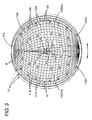
- Fig. 3 is a view specifically showing only the convex lens 12 and the light-emitting chip 14a in Fig. 1 .
- the first lens region 12Z1 is configured to deflect and diffuse the light emitted from the light emitting element 14 toward a first direction tilted by 7.5° in a right-up direction ("left-up direction" when viewed from the front side of the lamp) with respect to a direction perpendicular to the boundary line B.
- the second lens region 12Z2 is configured to deflect and diffuse the light emitted from the light emitting element 14 toward a second direction tilted by 7.5° in a left-up direction with respect to the direction perpendicular to the boundary line B.
- a portion located at the first lens region 12Z1 is formed as a right-up-direction diffusion region 12Z1a, and a portion located at the second lens region 12Z2 is formed as a left-up-direction diffusion region 12Z2a.
- the right-up-direction diffusion region 12Z1a is a region in which the light emitted from the light emitting element 14 and reaching the region 12Z1a is emitted as light deflected and diffused toward the right-up direction in the first direction.
- the left-up-direction diffusion region 12Z2a is a region in which light emitted from the light emitting element 14 and reaching the region 12Z2a is emitted as light deflected and diffused toward the left-up direction in the second direction.
- the deflection and diffusion control of the emitted light in the right-up-direction diffusion region 12Z1a is carried out by setting a direction of the emitted light for each position of the right-up-direction diffusion region 12Z1a.
- the right-up-direction diffusion region 12Z1a is divided into a plurality of cells C1.
- the plurality of cells C1 is formed by a plurality of curves L1c extending in the first direction at a uniform interval in the vertical direction and a plurality of curves L1m extending from the upper end point to the lower end point in a meridian shape.
- the direction of the emitted light is set for each cell C1.
- the direction of the emitted light in the cells C1 which are close to the boundary line B is slightly set to the right direction
- the direction of the emitted light in the cells C1 which are close to the outer peripheral edge of the convex lens 12 is set to the right direction at a comparatively larger amount
- the direction of the emitted light in the cells C1 located therebetween is set to the right direction at an amount therebetween.
- the direction of the emitted light is gradually changed in a horizontal plane from the cells C1 close to the boundary line B to the cells C1 close to the outer peripheral edge of the convex lens 12.
- the deflection and diffusion control of the light passing through the left-up-direction diffusion region 12Z2a is carried out by setting a direction of the emitted light for each position of the left-up-direction diffusion region 12Z2a, thereby performing the deflection and diffusion control so as to have a characteristic bilaterally symmetric with the right-up-direction diffusion region 12Z1a.
- the left-up-direction diffusion region 12Z2a is divided into a plurality of cells C2.
- the plurality of cells C2 is formed by a plurality of curves L2c extending in the first direction at a uniform interval in the vertical direction and a plurality of curves L2m extending from the upper end point to the lower end point in a meridian shape.
- the direction of the emitted light is set for each cell C2.
- the directions of the emitted light in the cells C2 which are close to the boundary line B are slightly set to the left direction
- the direction of the emitted light in the cells C2 which are close to the outer peripheral edge of the convex lens 12 is set to the left direction at a comparatively larger amount
- the direction of the emitted light in the cells C2 located therebetween is set to the left direction at an amount therebetween.
- the direction of the emitted light is gradually changed in a horizontal plane from the cells C2 close to the boundary line B to the cells C2 close to the outer peripheral edge of the convex lens 12.
- the arrows extending from each central position of the cells C1 and C2 in Fig. 3 indicates a direction where the light emitted from the middle point P3 in a horizontal direction of the lower edge 14a1 of the light-emitting chip 14a and being incident to the convex lens 12 passes through the cells C1 and C2.
- the front surface 12a of the convex lens 12 when the front surface 12a of the convex lens 12 is formed, the front surface 12a has a discontinuous surface shape in the boundary line B between the right-up-direction diffusion region 12Z1a and the left-up-direction diffusion region 12Z2a, and the boundary line B is formed as a ridge.
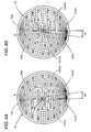
- Fig. 4A is a view showing the convex lens 12 located at a first angular position
- Fig. 4B is a view showing the convex lens 12 located at a second angular position.
- the convex lens 12 when the convex lens 12 is located at the first angular position, the central axis thereof passes through the left end point P1 of the lower edge 14a1 of the light-emitting chip 14a, and the boundary line B thereof is tilted in the right direction by 7.5° with respect to the perpendicular direction.
- the first direction is aligned with a horizontal direction
- the second direction is aligned with a direction which is tilted in the left-up direction by 15° with respect to the horizontal direction.
- the right-up-direction diffusion region 12Z1a of the first lens region 12Z1 deflects and diffuses the light emitted from the light emitting element 14 and reaching the region 12Z1a toward the right direction in a horizontal plane (i.e., a plane parallel to the lower edge 14a1 of the light-emitting chip 14a).
- the left-up-direction diffusion region 12Z2a of the second lens region 12Z2 deflects and diffuses the light emitted from the light emitting element 14 and reaching the region 12Z2a toward the left-up direction tilted by 15°.
- the central axis thereof passes through the right end point P2 of the lower edge 14a1 of the light-emitting chip 14a, and the boundary line B thereof is tilted in the left direction by 7.5° with respect to the perpendicular direction.
- the second direction is aligned with the horizontal direction
- the first direction is aligned with the right-up direction tilted by 15° with respect to the horizontal direction.
- the left-up-direction diffusion region 12Z2a of the second lens region 12Z2 deflects and diffuses the light emitted from the light emitting element 14 and reaching the region 12Z2a toward the left direction in a horizontal plane (i.e., a plane parallel to the lower edge 14a1 of the light-emitting chip 14a).
- the right-up-direction diffusion region 12Z1a of the first lens region 12Z1 deflects and diffuses the light emitted from the light emitting element 14 and reaching the region 12Z1a toward the right-up direction tilted by 15°.
- Fig. 5 is a perspective view showing a light distribution pattern PA which is formed on an imaginary vertical screen disposed at a position in front of the lamp by 25 meters.
- the light distribution pattern PA is formed by light irradiated from the vehicle lamp 10 according to this exemplary embodiment in a forward direction when the convex lens 12 is located at the first angular position.
- the light distribution pattern PA is a light distribution pattern which is formed as a part of the low beam light distribution pattern PL1 depicted by the dashed-two dotted line.
- the low beam light distribution pattern PL1 is a light distribution pattern which is formed by synthesizing the light distribution pattern PA with a light distribution pattern formed by light irradiated in a forward direction from another lamp unit (not shown).
- the low beam light distribution pattern PL1 is a low beam light distribution pattern of a left side light distribution pattern, whose upper end portion includes a horizontal cutoff line CL1 and a tilted cutoff line CL2.
- the horizontal cutoff line CL1 is formed on the right side (opposite lane side) thereof and the tilted cutoff line CL2 is formed on the left side (self lane side) thereof.
- An elbow point E as an intersection point between both cutoff lines CL1 and CL2, is located below the vanishing point H-V by about 0.5 to 0.6°.
- a hot zone HZ as a high-illumination region, is formed in the vicinity of the left side of the elbow point E.
- the light distribution pattern PA is a light distribution pattern which is formed by synthesizing the first light distribution pattern PA1 shown in Fig. 6A with the second light distribution pattern PA2 shown in Fig. 6B .
- a curve showing an outline thereof and a plurality of substantially concentric curves are iso-intensity curves.
- the light distribution pattern PA gradually becomes bright from the outer peripheral edge thereof to the center thereof.
- the light distribution pattern PA1 shown in Fig. 6A is a light distribution pattern which is formed by the light passing through the first lens region 12Z1, where an upper edge PA1a thereof is substantially aligned with the horizontal cutoff line CL1.
- the light distribution pattern PA2 shown in Fig. 6B is a light distribution pattern which is formed by the light passing through the second lens region 12Z2, where an upper edge PA2a thereof is substantially aligned with the tilted cutoff line CL2.
- the hot zone HZ of the low beam light distribution pattern PL1 is mainly formed by an overlap portion of two light distribution patterns PA1 and PA2.
- an inverse projection image Io of the light-emitting chip 14a is formed on the imaginary vertical screen so that the opposite-lane-side end point of an upper edge Ioa is located at the position of the elbow point E (i.e., the intersection point between the imaginary vertical screen and the optical axis Ax) and the upper edge Ioa is located on the horizontal line passing through the elbow point E.
- the lower edge 14a1 of the light-emitting chip 14a is located on the horizontal plane including the optical axis Ax and the left end point P1 of the lower edge 14a1 is located at the rear focal point F of the convex lens 12. Since the lower edge 14a1 of the light-emitting chip 14a extends in the horizontal direction from the rear focal point F of the convex lens 12, the upper edge Ioa of the inverse projection image Io has a high brightness ratio.
- the right-up-direction diffusion region 12Z1a located on the right side thereof deflects and diffuses the light emitted from the light emitting element 14 toward the right direction in the horizontal plane.
- the left-up-direction diffusion region 12Z2a located on the left side thereof deflects and diffuses the light emitted from the light emitting element 14 toward the left-up direction tilted by 15°.
- the light distribution pattern PA1 is formed on the imaginary vertical screen by the light passing through the right-up-direction diffusion region 12Z1a.
- the light distribution pattern PA1 is a light distribution pattern in which the inverse projection image Io is stretched in the right direction.
- the light distribution pattern PA2 is formed on the imaginary vertical screen by the light passing through the left-up-direction diffusion region 12Z2a.
- the light distribution pattern PA2 is a light distribution pattern in which the inverse projection image Io is stretched in the left-up direction tilted by 15° with respect to the horizontal direction.
- Fig. 6A shows a light distribution pattern PA1 obtained by overlapping a plurality of inverse projection images Iz1.
- the light distribution pattern PA1 forms a light distribution pattern in which the inverse projection image Io of the light-emitting chip 14a is stretched in the right direction with respect to the horizontal direction. Since the upper edge Ioa of the inverse projection image Io is located at the horizontal line passing through the elbow point E, the upper edge PA1 a of the light distribution pattern PA1 has a high brightness ratio, thereby making the horizontal cutoff line CL1 clear.
- Fig. 6B shows a light distribution pattern PA2 obtained by overlapping the plurality of inverse projection images Iz2.
- the light distribution pattern PA2 forms a light distribution pattern in which the inverse projection image Io of the light-emitting chip 14a is stretched in the left-up direction tilted by 15°. Since the extension direction of the upper edge Ioa of the inverse projection image Io is not aligned with the stretch direction of the inverse projection image Io, the upper edge PA2a of the light distribution pattern PA2 has a high brightness ratio, but one which is not higher than that of the upper edge PA1a of the light distribution pattern PA1. However, it is possible to make the tilted cutoff line CL2 clear to a certain degree.
- Fig. 7 is a perspective view showing a light distribution pattern PB which is formed on the imaginary vertical screen disposed at a position in front of the lamp by 25 meters.
- the light distribution pattern PB is formed by light irradiated from the vehicle lamp 10 according to this exemplary embodiment in a forward direction when the convex lens 12 is located at the second angular position.
- the light distribution pattern PB is a light distribution pattern which is formed as a part of the low beam light distribution pattern PL2 depicted by the dashed-two dotted line.
- the low beam light distribution pattern PL2 is formed by synthesizing the light distribution pattern PB with a light distribution pattern formed by the light irradiated in a forward direction from another lamp unit (not shown).
- the low beam light distribution pattern PL2 is a light distribution pattern of a right side light distribution pattern, whose upper end portion includes the horizontal cutoff line CL1 and the tilted cutoff line CL2.
- the horizontal cutoff line CL1 is formed on the left side (opposite lane side) thereof and the tilted cutoff line CL2 is formed on the right side (self lane side) thereof.
- the elbow point E is located below the vanishing point H-V by about 0.5° to 0.6°.
- the hot zone HZ is formed in the vicinity of the right side of the elbow point E.
- the light distribution pattern PB is a light distribution pattern which is formed by synthesizing the first light distribution pattern PB1 shown in Fig. 8A with the second light distribution pattern PB2 shown in Fig. 8B .
- a curve showing an outline thereof and a plurality of substantially concentric curves are iso-intensity curves.
- the light distribution pattern PB gradually becomes bright from the outer peripheral edge thereof to the center thereof.
- the light distribution pattern PB1 shown in Fig. 8A is a light distribution pattern which is formed by the light passing through the first lens region 12Z1, where an upper edge PB1a thereof is substantially aligned with the tilted cutoff line CL2.
- the light distribution pattern PB2 shown in Fig. 8B is a light distribution pattern which is formed by the light passing through the second lens region 12Z2, where an upper edge PB2a thereof is substantially aligned with the horizontal cutoff line CL1.
- the hot zone HZ of the low beam light distribution pattern PL2 is mainly formed by an overlap portion of two light distribution patterns PB1 and PB2.
- the inverse projection image Io of the light-emitting chip 14a is formed on the imaginary vertical screen so that the opposite-lane-side end point of the upper edge Ioa is located at the position of the elbow point E and the upper edge Ioa is located on the horizontal line passing through the elbow point E.
- the lower edge 14a1 of the light-emitting chip 14a is located on the horizontal plane including the optical axis Ax and the right end point P2 of the lower edge 14a1 is located at the rear focal point F of the convex lens 12. Since the lower edge 14a1 of the light-emitting chip 14a extends in the horizontal direction from the rear focal point F of the convex lens 12, the upper edge Ioa of the inverse projection image Io has a high brightness ratio.
- the right-up-direction diffusion region 12Z1a located on the right side thereof deflects and diffuses the light emitted from the light emitting element 14 toward the right-up direction tilted by 15°
- the left-up-direction diffusion region 12Z2a located on the left side thereof deflects and diffuses the light emitted from the light emitting element 14 toward the left direction in a horizontal plane.
- the light distribution pattern PB1 is formed on the imaginary vertical screen by the light passing through the right-up-direction diffusion region 12Z1a
- the light distribution pattern PB1 is a light distribution pattern in which the inverse projection image Io is stretched in the right-up direction tilted by 15°.
- the light distribution pattern PB2 is formed on the imaginary vertical screen by the light passing through the left-up-direction diffusion region 12Z2a, and the light distribution pattern PB2 is a light distribution pattern in which the inverse projection image Io is stretched in the left direction with respect to the horizontal direction.
- Fig. 8A shows a diffusion shape of the light distribution pattern PB1 obtained by overlapping the plurality of inverse projection images Iz1.
- the light distribution pattern PB1 forms a light distribution pattern in which the inverse projection image Io of the light-emitting chip 14a is stretched in the right-up direction tilted by 15°. Since the extension direction of the upper edge Ioa of the inverse projection image Io is not aligned with the stretch direction of the inverse projection image Io, the upper edge PB1a of the light distribution pattern PB1 has a high brightness ratio but one which is not higher than that of the upper edge PB2a of the light distribution pattern PB2. However, it is possible to make the tilted cutoff line CL2 clear to a certain degree.
- Fig. 8B shows the light distribution pattern PB2 obtained by overlapping the plurality of inverse projection images Iz2.
- the light distribution pattern PB2 forms a light distribution pattern in which the inverse projection image Io of the light-emitting chip 14a is stretched in the left direction with respect to the horizontal direction. Since the upper edge Ioa of the inverse projection image Io is located at the horizontal line passing through the elbow point E, the upper edge PB2a of the light distribution pattern PB2 has a high brightness ratio, thereby making the horizontal cutoff line CL1 clear.
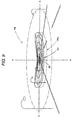
- Fig. 9 is a perspective view showing a light distribution pattern PC which is formed on the imaginary vertical screen disposed at a position in front of the lamp by 25 meters, and the light distribution pattern PC is formed by light irradiated from the vehicle lamp 10 according to this exemplary embodiment in a forward direction when the convex lens 12 is located at the third angular position.
- the light distribution pattern PC is a light distribution pattern which is formed as a part of the high beam light distribution pattern PH depicted by the dashed-two dotted line.
- the high beam light distribution pattern PH is formed by synthesizing the light distribution pattern PC with a light distribution pattern formed by the light irradiated in a forward direction from another lamp unit (not shown).
- the high beam light distribution pattern PH is a light distribution pattern which is horizontally-long about the vanishing point H-V and has a hot zone HZ in the vicinity of the vanishing point H-V.
- the light distribution pattern PC is a horizontally-long light distribution pattern which extends in the horizontal direction from the vicinity of the vanishing point H-V along the horizontal line H-H passing through the vanishing point H-V and has the hot zone HZ in the vicinity of the vanishing point H-V.
- the both end portions of the light distribution pattern PC are curved slightly upward.
- the light distribution pattern PC is formed by driving a tilting mechanism 24 so as to displace upward a light distribution pattern PCo (which is depicted by the dashed-two dotted line in Fig. 9 ).
- the light distribution pattern PCo is formed by synthesizing a first light distribution pattern PCo1 shown in Fig. 10A with a second light distribution pattern PCo2 shown in Fig. 10B .
- a curve showing an outline thereof and a plurality of substantially concentric curves are iso-intensity curves.
- the light distribution pattern PC gradually becomes bright from the outer peripheral edge thereof to the center thereof.
- the light distribution pattern PCo1 shown in Fig. 10A is a light distribution pattern which is formed by the light passing through the first lens region 12Z1, where the light distribution pattern PCo1 extends from a position below the vanishing point H-V toward the right-up direction tilted by 7.5°.
- the light distribution pattern PCo2 shown in Fig. 10B is a light distribution pattern which is formed by the light passing through the second lens region 12Z2, where the light distribution pattern PCo2 extends from a position below the vanishing point H-V toward the left-up direction tilted by 7.5°.
- the hot zone HZ of the high beam light distribution pattern PH is mainly formed by an overlapping portion of two light distribution patterns PCo1 and PCo2.
- the direct light emitted from the light emitting element 14 is controlled and deflected by the convex lens 12 so as to form the light distribution patterns PA and PB whose upper end portions have the horizontal cutoff line CL1 and the tilted cutoff line CL2.
- the substantially right half portion of the convex lens 12 is formed as the first lens region 12Z1 which is used to deflect and diffuse the light emitted from the light emitting element 14 toward the first direction.
- the substantially left half portion thereof is formed as the second lens region 12Z2 which is used to deflect and diffuse the light emitted from the light emitting element 14 toward the second direction forming an obtuse angle with respect to the first direction.
- the convex lens 12 is disposed so as to be rotatable about the axis Ax1 which is disposed above the optical axis Ax and extends parallel thereto. Further, the first angular position where the first direction is the horizontal direction and the second angular position where the second direction is the horizontal direction can be selected. Accordingly, the following advantages can be obtained.
- the inverse projection image of the light-emitting chip 14a is formed on the imaginary vertical screen in front of the lamp.
- the first direction is substantially aligned with the horizontal direction when the convex lens 12 is located at the first angular position.
- the light passing through the first lens region 12Z1 is deflected and diffused toward the horizontal direction.
- the light emitted from the second lens region 12Z2 is deflected and diffused toward a tilted direction forming an obtuse angle with respect to the horizontal direction. Accordingly, the light distribution pattern PA for the left light distribution, whose upper end portion has the horizontal cutoff line CL1 and the tilted cutoff line CL2, is formed.
- the second direction is substantially aligned with the horizontal direction when the convex lens 12 is located at the second angular position.
- the light passing through the second lens region 12Z2 is deflected and diffused toward the horizontal direction.
- the light passing through the first lens region 12Z1 is deflected and diffused toward a tilted angle forming an obtuse angle with respect to the horizontal direction.
- the light distribution pattern PB for the right light distribution whose upper end portion has the horizontal cutoff line CL1 and the tilted cutoff line CL2, is formed.
- the light distribution pattern PA for the left light distribution and the light distribution pattern PB for the right light distribution can be switched from one to the other and vice versa such that the position of the light emitting element 14 is constant and the convex lens 12 is rotated about the axis Ax1 located above the optical axis Ax. Accordingly, as compared with the known technology in which the left light distribution pattern is just rotated by a predetermined angle while maintaining the shape and light intensity distribution thereof to be uniform so as to form the right light distribution pattern, it is possible to form the light distribution pattern PB for the right light distribution as a light distribution pattern which has the shape and light intensity distribution bilaterally symmetric with the light distribution pattern PA for the left light distribution.
- the vehicle lamp 10 using the light emitting element 14 as a light source it is possible to switch the left light distribution and the right light distribution from one to the other. Additionally, it is possible to form any one of the light distribution patterns PA and PB for the left light distribution and the right light distribution so as to have the appropriate shape and light intensity distribution. In addition, it is possible to decrease the size of the driving mechanism 22 for performing the switching operation.
- the light emitting element 14 including the rectangular light-emitting chip 14a is disposed such that the lower edge 14a1 of the light-emitting chip 14a is located on the horizontal plane including the optical axis Ax and the middle point P3 in the horizontal direction of the lower edge 14a1 is located on the optical axis Ax.
- the position of the axis Ax1 is set such that the boundary line B between the first lens region 12Z1 and the second lens region 12Z2 passes through the left end point P1 of the lower edge 14a1 of the light-emitting chip 14a when the convex lens 12 is located at the first angular position, and the boundary line B passes through the right end point P2 of the lower edge 14a1 of the light-emitting chip 14a when the convex lens 12 is located at the second angular position. Accordingly, the following advantage can be obtained.
- the central axis of the convex lens 12 is located at the left end point P1 of the lower edge 14a1 of the light-emitting chip 14a when the convex lens 12 is located at the first angular position. For this reason, when the light passing through the first lens region 12Z1 is deflected and diffused toward the horizontal direction, it is possible to obtain the horizontal cutoff line CL1 having a high brightness ratio. Also, when the light passing through the second lens region 12Z2 is deflected and diffused toward the tilted direction forming an obtuse angle with respect to the horizontal direction, it is possible to obtain the tilted cutoff line CL2 having a high brightness ratio, but one which is not higher than that of the horizontal cutoff line CL1.
- the central axis of the convex lens 12 is located at the right end point P2 of the lower edge 14a1 of the light-emitting chip 14a.
- the horizontal cutoff line CL1 having a high brightness ratio.
- the tilted cutoff line CL2 having a high brightness ratio but one which is not higher than that of the horizontal cutoff line CL1.
- the convex lens 12 is capable of selecting the third angular position located in the middle of the first and second angular positions. Accordingly, when the convex lens 12 is located at the third angular position, the light passing through the first and second lens regions 12Z1 and 12Z2 becomes light which is deflected and diffused obliquely upward in the horizontal direction at a middle angle between the horizontal direction and the tilted direction.
- the convex lens 12 when the convex lens 12 is rotated to the third angular position upon turning on the high beam, it is possible to form the light distribution pattern PCo of which both end portions are curved slightly upward. Accordingly, it is possible to improve a visualizing performance for seeing road shoulders on both left and right sides of a road surface in front of the vehicle.
- the light distribution pattern PCo is displaced upward by the tilting mechanism 24 so as to obtain the light distribution pattern PC. Accordingly, it is possible to improve the visualizing performance for seeing a far area of the road surface in front of the vehicle and to further improve the visualizing performance for seeing the road shoulders on both left and right sides of the road surface.
- the rear surface 12b of the convex lens 12 is formed as a flat surface, but the rear surface may be formed as a convex surface or a concave surface.
- the size of the included angle may be an appropriate value other than 165° as long as the angle is an obtuse angle. It is advantageous that the value be not less than 135°.
- the driving mechanism 22 used for rotating the convex lens 12 about the axis Ax1 includes: the gear-shaped portion 20b formed on the outer peripheral surface 20a of the lens holder 20; and the pinion 22a meshing with the gear-shaped portion, but other mechanisms (e.g., a rack and pinion mechanism, a solenoid capable of selecting three positions) may be used.
- the tilting mechanism 24 for displacing upward the entire part of the vehicle lamp 10 is provided to displace upward the light distribution pattern PCo when the convex lens 12 is located at the third angular position, but other mechanisms (e.g., a mechanism for displacing downward the light emitting element 14, a mechanism for displacing upward the convex lens 12) may be used to displace upward the light distribution pattern PCo.
- the third angular position is located in the middle of the first and second angular positions, but the third angular position may be located at a position slightly away from the center.
- the dimension data is an example, and may be, of course, set to appropriately different values.
Landscapes
- Engineering & Computer Science (AREA)
- General Engineering & Computer Science (AREA)
- Non-Portable Lighting Devices Or Systems Thereof (AREA)
Applications Claiming Priority (1)
| Application Number | Priority Date | Filing Date | Title |
|---|---|---|---|
| JP2008162835A JP2010003604A (ja) | 2008-06-23 | 2008-06-23 | 車両用照明灯具 |
Publications (3)
| Publication Number | Publication Date |
|---|---|
| EP2138760A2 true EP2138760A2 (de) | 2009-12-30 |
| EP2138760A3 EP2138760A3 (de) | 2011-04-06 |
| EP2138760B1 EP2138760B1 (de) | 2012-12-12 |
Family
ID=41151787
Family Applications (1)
| Application Number | Title | Priority Date | Filing Date |
|---|---|---|---|
| EP09163503A Not-in-force EP2138760B1 (de) | 2008-06-23 | 2009-06-23 | Fahrzeuglampe |
Country Status (2)
| Country | Link |
|---|---|
| EP (1) | EP2138760B1 (de) |
| JP (1) | JP2010003604A (de) |
Cited By (3)
| Publication number | Priority date | Publication date | Assignee | Title |
|---|---|---|---|---|
| WO2012098142A1 (fr) * | 2011-01-20 | 2012-07-26 | Valeo Vision | Module de projection d'un faisceau |
| WO2014012878A1 (fr) * | 2012-07-19 | 2014-01-23 | Valeo Vision Belgique | Dispositif d'emission d'un faisceau lumineux et projecteur, notamment pour vehicule automobile, comprenant ledit dispositif |
| EP2565521A3 (de) * | 2011-08-31 | 2017-08-30 | Ichikoh Industries, Ltd. | Fahrzeugscheinwerfer |
Family Cites Families (5)
| Publication number | Priority date | Publication date | Assignee | Title |
|---|---|---|---|---|
| US6186651B1 (en) * | 1999-07-21 | 2001-02-13 | Visteon Global Technologies, Inc. | Bifunctional high intensity discharge projector headlamp |
| JP4261452B2 (ja) * | 2004-01-23 | 2009-04-30 | 株式会社小糸製作所 | 車両用前照灯 |
| JP2005235708A (ja) * | 2004-02-23 | 2005-09-02 | Ichikoh Ind Ltd | プロジェクタ型車両用灯具 |
| AT504505B1 (de) * | 2006-10-23 | 2008-06-15 | Zizala Lichtsysteme Gmbh | Optikelement für einen fahrzeugscheinwerfer |
| DE202007018181U1 (de) * | 2007-12-31 | 2008-05-08 | Automotive Lighting Reutlingen Gmbh | Projektionsmodul mit dynamischer Kurvenlichtfunktion |
-
2008
- 2008-06-23 JP JP2008162835A patent/JP2010003604A/ja active Pending
-
2009
- 2009-06-23 EP EP09163503A patent/EP2138760B1/de not_active Not-in-force
Non-Patent Citations (1)
| Title |
|---|
| None |
Cited By (9)
| Publication number | Priority date | Publication date | Assignee | Title |
|---|---|---|---|---|
| WO2012098142A1 (fr) * | 2011-01-20 | 2012-07-26 | Valeo Vision | Module de projection d'un faisceau |
| FR2973861A1 (fr) * | 2011-01-20 | 2012-10-12 | Valeo Vision | Module de projection d'un faisceau |
| EP2565521A3 (de) * | 2011-08-31 | 2017-08-30 | Ichikoh Industries, Ltd. | Fahrzeugscheinwerfer |
| WO2014012878A1 (fr) * | 2012-07-19 | 2014-01-23 | Valeo Vision Belgique | Dispositif d'emission d'un faisceau lumineux et projecteur, notamment pour vehicule automobile, comprenant ledit dispositif |
| FR2993632A1 (fr) * | 2012-07-19 | 2014-01-24 | Valeo Vision Belgique | Dispositif d'emission d'un faisceau lumineux et projecteur, notamment de vehicule automobile, comprenant ledit dispositif |
| CN105008793A (zh) * | 2012-07-19 | 2015-10-28 | 法雷奥照明比利时公司 | 光束发射装置以及特别是用于机动车的包括该装置的灯 |
| RU2597206C1 (ru) * | 2012-07-19 | 2016-09-10 | Валео Визьон Бельжик | Устройство излучения светового пучка и фара, в частности, автотранспортного средства, содержащая указанное устройство |
| US9664353B2 (en) | 2012-07-19 | 2017-05-30 | Valeo Vision Belgique | Device for emitting a light beam and light, especially for an automotive vehicle, comprising said device |
| CN105008793B (zh) * | 2012-07-19 | 2018-04-27 | 法雷奥照明比利时公司 | 光束发射装置以及特别是用于机动车的包括该装置的灯 |
Also Published As
| Publication number | Publication date |
|---|---|
| EP2138760A3 (de) | 2011-04-06 |
| EP2138760B1 (de) | 2012-12-12 |
| JP2010003604A (ja) | 2010-01-07 |
Similar Documents
| Publication | Publication Date | Title |
|---|---|---|
| US7204627B2 (en) | Lamp unit for forming a cut-off line and vehicular headlamp using the same | |
| CN112805500B (zh) | 车辆用灯具 | |
| JP4964753B2 (ja) | 車両用照明灯具 | |
| CN100557296C (zh) | 车辆用前照灯的灯具单元 | |
| CN106574762B (zh) | 车辆用灯具 | |
| US10359169B2 (en) | Lamp unit and vehicle headlamp | |
| JP4982269B2 (ja) | 車両用照明灯具 | |
| CN101285561B (zh) | 车辆用灯具单元 | |
| JP5157883B2 (ja) | 車両用前照灯 | |
| JP5133862B2 (ja) | 車両用照明灯具 | |
| JP4663548B2 (ja) | 車両用前照灯の灯具ユニット | |
| JP5235502B2 (ja) | 車両用照明灯具 | |
| EP2405187A1 (de) | Lampeneinheit | |
| US7866863B2 (en) | Vehicle lamp | |
| US20050248955A1 (en) | Vehicle headlamp | |
| US10378716B2 (en) | Vehicle lamp | |
| CN111550745B (zh) | 车辆用灯具 | |
| EP2172694B1 (de) | Fahrzeuglampe | |
| US7210831B2 (en) | Vehicle illumination lamp | |
| EP2138760B1 (de) | Fahrzeuglampe | |
| JP2020057631A (ja) | 車両用灯具 | |
| JP2007234562A (ja) | 車両用前照灯の灯具ユニット | |
| JP2024169903A (ja) | 車両用灯具 |
Legal Events
| Date | Code | Title | Description |
|---|---|---|---|
| PUAI | Public reference made under article 153(3) epc to a published international application that has entered the european phase |
Free format text: ORIGINAL CODE: 0009012 |
|
| 17P | Request for examination filed |
Effective date: 20090623 |
|
| AK | Designated contracting states |
Kind code of ref document: A2 Designated state(s): AT BE BG CH CY CZ DE DK EE ES FI FR GB GR HR HU IE IS IT LI LT LU LV MC MK MT NL NO PL PT RO SE SI SK TR |
|
| PUAL | Search report despatched |
Free format text: ORIGINAL CODE: 0009013 |
|
| AK | Designated contracting states |
Kind code of ref document: A3 Designated state(s): AT BE BG CH CY CZ DE DK EE ES FI FR GB GR HR HU IE IS IT LI LT LU LV MC MK MT NL NO PL PT RO SE SI SK TR |
|
| AX | Request for extension of the european patent |
Extension state: AL BA RS |
|
| GRAP | Despatch of communication of intention to grant a patent |
Free format text: ORIGINAL CODE: EPIDOSNIGR1 |
|
| RIC1 | Information provided on ipc code assigned before grant |
Ipc: F21V 14/04 20060101ALI20120709BHEP Ipc: F21S 8/12 20060101AFI20120709BHEP Ipc: F21W 101/10 20060101ALN20120709BHEP |
|
| GRAS | Grant fee paid |
Free format text: ORIGINAL CODE: EPIDOSNIGR3 |
|
| GRAA | (expected) grant |
Free format text: ORIGINAL CODE: 0009210 |
|
| AK | Designated contracting states |
Kind code of ref document: B1 Designated state(s): AT BE BG CH CY CZ DE DK EE ES FI FR GB GR HR HU IE IS IT LI LT LU LV MC MK MT NL NO PL PT RO SE SI SK TR |
|
| REG | Reference to a national code |
Ref country code: GB Ref legal event code: FG4D |
|
| RIN1 | Information on inventor provided before grant (corrected) |
Inventor name: YAGI, TAKAYUKI C/O KOITO MANUFACTURING CO., LTD. |
|
| REG | Reference to a national code |
Ref country code: CH Ref legal event code: EP |
|
| REG | Reference to a national code |
Ref country code: AT Ref legal event code: REF Ref document number: 588510 Country of ref document: AT Kind code of ref document: T Effective date: 20121215 |
|
| REG | Reference to a national code |
Ref country code: IE Ref legal event code: FG4D |
|
| REG | Reference to a national code |
Ref country code: DE Ref legal event code: R096 Ref document number: 602009011858 Country of ref document: DE Effective date: 20130207 |
|
| PG25 | Lapsed in a contracting state [announced via postgrant information from national office to epo] |
Ref country code: NO Free format text: LAPSE BECAUSE OF FAILURE TO SUBMIT A TRANSLATION OF THE DESCRIPTION OR TO PAY THE FEE WITHIN THE PRESCRIBED TIME-LIMIT Effective date: 20130312 Ref country code: ES Free format text: LAPSE BECAUSE OF FAILURE TO SUBMIT A TRANSLATION OF THE DESCRIPTION OR TO PAY THE FEE WITHIN THE PRESCRIBED TIME-LIMIT Effective date: 20130323 Ref country code: LT Free format text: LAPSE BECAUSE OF FAILURE TO SUBMIT A TRANSLATION OF THE DESCRIPTION OR TO PAY THE FEE WITHIN THE PRESCRIBED TIME-LIMIT Effective date: 20121212 Ref country code: HR Free format text: LAPSE BECAUSE OF FAILURE TO SUBMIT A TRANSLATION OF THE DESCRIPTION OR TO PAY THE FEE WITHIN THE PRESCRIBED TIME-LIMIT Effective date: 20121212 Ref country code: SE Free format text: LAPSE BECAUSE OF FAILURE TO SUBMIT A TRANSLATION OF THE DESCRIPTION OR TO PAY THE FEE WITHIN THE PRESCRIBED TIME-LIMIT Effective date: 20121212 Ref country code: FI Free format text: LAPSE BECAUSE OF FAILURE TO SUBMIT A TRANSLATION OF THE DESCRIPTION OR TO PAY THE FEE WITHIN THE PRESCRIBED TIME-LIMIT Effective date: 20121212 |
|
| REG | Reference to a national code |
Ref country code: NL Ref legal event code: VDEP Effective date: 20121212 |
|
| REG | Reference to a national code |
Ref country code: AT Ref legal event code: MK05 Ref document number: 588510 Country of ref document: AT Kind code of ref document: T Effective date: 20121212 |
|
| REG | Reference to a national code |
Ref country code: LT Ref legal event code: MG4D |
|
| PG25 | Lapsed in a contracting state [announced via postgrant information from national office to epo] |
Ref country code: LV Free format text: LAPSE BECAUSE OF FAILURE TO SUBMIT A TRANSLATION OF THE DESCRIPTION OR TO PAY THE FEE WITHIN THE PRESCRIBED TIME-LIMIT Effective date: 20121212 Ref country code: SI Free format text: LAPSE BECAUSE OF FAILURE TO SUBMIT A TRANSLATION OF THE DESCRIPTION OR TO PAY THE FEE WITHIN THE PRESCRIBED TIME-LIMIT Effective date: 20121212 Ref country code: GR Free format text: LAPSE BECAUSE OF FAILURE TO SUBMIT A TRANSLATION OF THE DESCRIPTION OR TO PAY THE FEE WITHIN THE PRESCRIBED TIME-LIMIT Effective date: 20130313 |
|
| PG25 | Lapsed in a contracting state [announced via postgrant information from national office to epo] |
Ref country code: AT Free format text: LAPSE BECAUSE OF FAILURE TO SUBMIT A TRANSLATION OF THE DESCRIPTION OR TO PAY THE FEE WITHIN THE PRESCRIBED TIME-LIMIT Effective date: 20121212 Ref country code: IS Free format text: LAPSE BECAUSE OF FAILURE TO SUBMIT A TRANSLATION OF THE DESCRIPTION OR TO PAY THE FEE WITHIN THE PRESCRIBED TIME-LIMIT Effective date: 20130412 Ref country code: CZ Free format text: LAPSE BECAUSE OF FAILURE TO SUBMIT A TRANSLATION OF THE DESCRIPTION OR TO PAY THE FEE WITHIN THE PRESCRIBED TIME-LIMIT Effective date: 20121212 Ref country code: BE Free format text: LAPSE BECAUSE OF FAILURE TO SUBMIT A TRANSLATION OF THE DESCRIPTION OR TO PAY THE FEE WITHIN THE PRESCRIBED TIME-LIMIT Effective date: 20121212 Ref country code: SK Free format text: LAPSE BECAUSE OF FAILURE TO SUBMIT A TRANSLATION OF THE DESCRIPTION OR TO PAY THE FEE WITHIN THE PRESCRIBED TIME-LIMIT Effective date: 20121212 Ref country code: BG Free format text: LAPSE BECAUSE OF FAILURE TO SUBMIT A TRANSLATION OF THE DESCRIPTION OR TO PAY THE FEE WITHIN THE PRESCRIBED TIME-LIMIT Effective date: 20130312 Ref country code: EE Free format text: LAPSE BECAUSE OF FAILURE TO SUBMIT A TRANSLATION OF THE DESCRIPTION OR TO PAY THE FEE WITHIN THE PRESCRIBED TIME-LIMIT Effective date: 20121212 |
|
| PG25 | Lapsed in a contracting state [announced via postgrant information from national office to epo] |
Ref country code: PT Free format text: LAPSE BECAUSE OF FAILURE TO SUBMIT A TRANSLATION OF THE DESCRIPTION OR TO PAY THE FEE WITHIN THE PRESCRIBED TIME-LIMIT Effective date: 20130412 Ref country code: PL Free format text: LAPSE BECAUSE OF FAILURE TO SUBMIT A TRANSLATION OF THE DESCRIPTION OR TO PAY THE FEE WITHIN THE PRESCRIBED TIME-LIMIT Effective date: 20121212 Ref country code: RO Free format text: LAPSE BECAUSE OF FAILURE TO SUBMIT A TRANSLATION OF THE DESCRIPTION OR TO PAY THE FEE WITHIN THE PRESCRIBED TIME-LIMIT Effective date: 20121212 Ref country code: NL Free format text: LAPSE BECAUSE OF FAILURE TO SUBMIT A TRANSLATION OF THE DESCRIPTION OR TO PAY THE FEE WITHIN THE PRESCRIBED TIME-LIMIT Effective date: 20121212 |
|
| PLBE | No opposition filed within time limit |
Free format text: ORIGINAL CODE: 0009261 |
|
| STAA | Information on the status of an ep patent application or granted ep patent |
Free format text: STATUS: NO OPPOSITION FILED WITHIN TIME LIMIT |
|
| PG25 | Lapsed in a contracting state [announced via postgrant information from national office to epo] |
Ref country code: DK Free format text: LAPSE BECAUSE OF FAILURE TO SUBMIT A TRANSLATION OF THE DESCRIPTION OR TO PAY THE FEE WITHIN THE PRESCRIBED TIME-LIMIT Effective date: 20121212 |
|
| 26N | No opposition filed |
Effective date: 20130913 |
|
| PG25 | Lapsed in a contracting state [announced via postgrant information from national office to epo] |
Ref country code: CY Free format text: LAPSE BECAUSE OF FAILURE TO SUBMIT A TRANSLATION OF THE DESCRIPTION OR TO PAY THE FEE WITHIN THE PRESCRIBED TIME-LIMIT Effective date: 20121212 |
|
| PG25 | Lapsed in a contracting state [announced via postgrant information from national office to epo] |
Ref country code: IT Free format text: LAPSE BECAUSE OF FAILURE TO SUBMIT A TRANSLATION OF THE DESCRIPTION OR TO PAY THE FEE WITHIN THE PRESCRIBED TIME-LIMIT Effective date: 20121212 |
|
| REG | Reference to a national code |
Ref country code: DE Ref legal event code: R097 Ref document number: 602009011858 Country of ref document: DE Effective date: 20130913 |
|
| PG25 | Lapsed in a contracting state [announced via postgrant information from national office to epo] |
Ref country code: MC Free format text: LAPSE BECAUSE OF FAILURE TO SUBMIT A TRANSLATION OF THE DESCRIPTION OR TO PAY THE FEE WITHIN THE PRESCRIBED TIME-LIMIT Effective date: 20121212 |
|
| REG | Reference to a national code |
Ref country code: CH Ref legal event code: PL |
|
| REG | Reference to a national code |
Ref country code: IE Ref legal event code: MM4A |
|
| PG25 | Lapsed in a contracting state [announced via postgrant information from national office to epo] |
Ref country code: IE Free format text: LAPSE BECAUSE OF NON-PAYMENT OF DUE FEES Effective date: 20130623 Ref country code: CH Free format text: LAPSE BECAUSE OF NON-PAYMENT OF DUE FEES Effective date: 20130630 Ref country code: LI Free format text: LAPSE BECAUSE OF NON-PAYMENT OF DUE FEES Effective date: 20130630 |
|
| PGFP | Annual fee paid to national office [announced via postgrant information from national office to epo] |
Ref country code: GB Payment date: 20140618 Year of fee payment: 6 |
|
| PGFP | Annual fee paid to national office [announced via postgrant information from national office to epo] |
Ref country code: DE Payment date: 20140618 Year of fee payment: 6 |
|
| PGFP | Annual fee paid to national office [announced via postgrant information from national office to epo] |
Ref country code: FR Payment date: 20140609 Year of fee payment: 6 |
|
| PG25 | Lapsed in a contracting state [announced via postgrant information from national office to epo] |
Ref country code: MT Free format text: LAPSE BECAUSE OF FAILURE TO SUBMIT A TRANSLATION OF THE DESCRIPTION OR TO PAY THE FEE WITHIN THE PRESCRIBED TIME-LIMIT Effective date: 20121212 |
|
| PG25 | Lapsed in a contracting state [announced via postgrant information from national office to epo] |
Ref country code: TR Free format text: LAPSE BECAUSE OF FAILURE TO SUBMIT A TRANSLATION OF THE DESCRIPTION OR TO PAY THE FEE WITHIN THE PRESCRIBED TIME-LIMIT Effective date: 20121212 |
|
| PG25 | Lapsed in a contracting state [announced via postgrant information from national office to epo] |
Ref country code: HU Free format text: LAPSE BECAUSE OF FAILURE TO SUBMIT A TRANSLATION OF THE DESCRIPTION OR TO PAY THE FEE WITHIN THE PRESCRIBED TIME-LIMIT; INVALID AB INITIO Effective date: 20090623 Ref country code: MK Free format text: LAPSE BECAUSE OF FAILURE TO SUBMIT A TRANSLATION OF THE DESCRIPTION OR TO PAY THE FEE WITHIN THE PRESCRIBED TIME-LIMIT Effective date: 20121212 Ref country code: LU Free format text: LAPSE BECAUSE OF NON-PAYMENT OF DUE FEES Effective date: 20130623 |
|
| REG | Reference to a national code |
Ref country code: DE Ref legal event code: R119 Ref document number: 602009011858 Country of ref document: DE |
|
| GBPC | Gb: european patent ceased through non-payment of renewal fee |
Effective date: 20150623 |
|
| REG | Reference to a national code |
Ref country code: FR Ref legal event code: ST Effective date: 20160229 |
|
| PG25 | Lapsed in a contracting state [announced via postgrant information from national office to epo] |
Ref country code: DE Free format text: LAPSE BECAUSE OF NON-PAYMENT OF DUE FEES Effective date: 20160101 Ref country code: GB Free format text: LAPSE BECAUSE OF NON-PAYMENT OF DUE FEES Effective date: 20150623 |
|
| PG25 | Lapsed in a contracting state [announced via postgrant information from national office to epo] |
Ref country code: FR Free format text: LAPSE BECAUSE OF NON-PAYMENT OF DUE FEES Effective date: 20150630 |