EP2138263B1 - Method of Manufacturing a Blade - Google Patents
Method of Manufacturing a Blade Download PDFInfo
- Publication number
- EP2138263B1 EP2138263B1 EP09163418.8A EP09163418A EP2138263B1 EP 2138263 B1 EP2138263 B1 EP 2138263B1 EP 09163418 A EP09163418 A EP 09163418A EP 2138263 B1 EP2138263 B1 EP 2138263B1
- Authority
- EP
- European Patent Office
- Prior art keywords
- steel strip
- hard material
- blade
- mixture
- dispenser
- Prior art date
- Legal status (The legal status is an assumption and is not a legal conclusion. Google has not performed a legal analysis and makes no representation as to the accuracy of the status listed.)
- Active
Links
Images


Classifications
-
- B—PERFORMING OPERATIONS; TRANSPORTING
- B23—MACHINE TOOLS; METAL-WORKING NOT OTHERWISE PROVIDED FOR
- B23P—METAL-WORKING NOT OTHERWISE PROVIDED FOR; COMBINED OPERATIONS; UNIVERSAL MACHINE TOOLS
- B23P15/00—Making specific metal objects by operations not covered by a single other subclass or a group in this subclass
- B23P15/28—Making specific metal objects by operations not covered by a single other subclass or a group in this subclass cutting tools
- B23P15/40—Making specific metal objects by operations not covered by a single other subclass or a group in this subclass cutting tools shearing tools
-
- B—PERFORMING OPERATIONS; TRANSPORTING
- B23—MACHINE TOOLS; METAL-WORKING NOT OTHERWISE PROVIDED FOR
- B23D—PLANING; SLOTTING; SHEARING; BROACHING; SAWING; FILING; SCRAPING; LIKE OPERATIONS FOR WORKING METAL BY REMOVING MATERIAL, NOT OTHERWISE PROVIDED FOR
- B23D65/00—Making tools for sawing machines or sawing devices for use in cutting any kind of material
-
- B—PERFORMING OPERATIONS; TRANSPORTING
- B23—MACHINE TOOLS; METAL-WORKING NOT OTHERWISE PROVIDED FOR
- B23K—SOLDERING OR UNSOLDERING; WELDING; CLADDING OR PLATING BY SOLDERING OR WELDING; CUTTING BY APPLYING HEAT LOCALLY, e.g. FLAME CUTTING; WORKING BY LASER BEAM
- B23K15/00—Electron-beam welding or cutting
- B23K15/0046—Welding
- B23K15/0086—Welding welding for purposes other than joining, e.g. built-up welding
-
- B—PERFORMING OPERATIONS; TRANSPORTING
- B23—MACHINE TOOLS; METAL-WORKING NOT OTHERWISE PROVIDED FOR
- B23K—SOLDERING OR UNSOLDERING; WELDING; CLADDING OR PLATING BY SOLDERING OR WELDING; CUTTING BY APPLYING HEAT LOCALLY, e.g. FLAME CUTTING; WORKING BY LASER BEAM
- B23K15/00—Electron-beam welding or cutting
- B23K15/0046—Welding
- B23K15/0093—Welding characterised by the properties of the materials to be welded
-
- B—PERFORMING OPERATIONS; TRANSPORTING
- B23—MACHINE TOOLS; METAL-WORKING NOT OTHERWISE PROVIDED FOR
- B23K—SOLDERING OR UNSOLDERING; WELDING; CLADDING OR PLATING BY SOLDERING OR WELDING; CUTTING BY APPLYING HEAT LOCALLY, e.g. FLAME CUTTING; WORKING BY LASER BEAM
- B23K26/00—Working by laser beam, e.g. welding, cutting or boring
- B23K26/14—Working by laser beam, e.g. welding, cutting or boring using a fluid stream, e.g. a jet of gas, in conjunction with the laser beam; Nozzles therefor
- B23K26/144—Working by laser beam, e.g. welding, cutting or boring using a fluid stream, e.g. a jet of gas, in conjunction with the laser beam; Nozzles therefor the fluid stream containing particles, e.g. powder
-
- B—PERFORMING OPERATIONS; TRANSPORTING
- B23—MACHINE TOOLS; METAL-WORKING NOT OTHERWISE PROVIDED FOR
- B23K—SOLDERING OR UNSOLDERING; WELDING; CLADDING OR PLATING BY SOLDERING OR WELDING; CUTTING BY APPLYING HEAT LOCALLY, e.g. FLAME CUTTING; WORKING BY LASER BEAM
- B23K26/00—Working by laser beam, e.g. welding, cutting or boring
- B23K26/20—Bonding
- B23K26/32—Bonding taking account of the properties of the material involved
-
- B—PERFORMING OPERATIONS; TRANSPORTING
- B23—MACHINE TOOLS; METAL-WORKING NOT OTHERWISE PROVIDED FOR
- B23K—SOLDERING OR UNSOLDERING; WELDING; CLADDING OR PLATING BY SOLDERING OR WELDING; CUTTING BY APPLYING HEAT LOCALLY, e.g. FLAME CUTTING; WORKING BY LASER BEAM
- B23K26/00—Working by laser beam, e.g. welding, cutting or boring
- B23K26/34—Laser welding for purposes other than joining
-
- B—PERFORMING OPERATIONS; TRANSPORTING
- B23—MACHINE TOOLS; METAL-WORKING NOT OTHERWISE PROVIDED FOR
- B23K—SOLDERING OR UNSOLDERING; WELDING; CLADDING OR PLATING BY SOLDERING OR WELDING; CUTTING BY APPLYING HEAT LOCALLY, e.g. FLAME CUTTING; WORKING BY LASER BEAM
- B23K31/00—Processes relevant to this subclass, specially adapted for particular articles or purposes, but not covered by only one of the preceding main groups
- B23K31/02—Processes relevant to this subclass, specially adapted for particular articles or purposes, but not covered by only one of the preceding main groups relating to soldering or welding
- B23K31/025—Connecting cutting edges or the like to tools; Attaching reinforcements to workpieces, e.g. wear-resisting zones to tableware
-
- B—PERFORMING OPERATIONS; TRANSPORTING
- B23—MACHINE TOOLS; METAL-WORKING NOT OTHERWISE PROVIDED FOR
- B23K—SOLDERING OR UNSOLDERING; WELDING; CLADDING OR PLATING BY SOLDERING OR WELDING; CUTTING BY APPLYING HEAT LOCALLY, e.g. FLAME CUTTING; WORKING BY LASER BEAM
- B23K35/00—Rods, electrodes, materials, or media, for use in soldering, welding, or cutting
- B23K35/02—Rods, electrodes, materials, or media, for use in soldering, welding, or cutting characterised by mechanical features, e.g. shape
- B23K35/0222—Rods, electrodes, materials, or media, for use in soldering, welding, or cutting characterised by mechanical features, e.g. shape for use in soldering, brazing
- B23K35/0244—Powders, particles or spheres; Preforms made therefrom
-
- B—PERFORMING OPERATIONS; TRANSPORTING
- B23—MACHINE TOOLS; METAL-WORKING NOT OTHERWISE PROVIDED FOR
- B23K—SOLDERING OR UNSOLDERING; WELDING; CLADDING OR PLATING BY SOLDERING OR WELDING; CUTTING BY APPLYING HEAT LOCALLY, e.g. FLAME CUTTING; WORKING BY LASER BEAM
- B23K35/00—Rods, electrodes, materials, or media, for use in soldering, welding, or cutting
- B23K35/22—Rods, electrodes, materials, or media, for use in soldering, welding, or cutting characterised by the composition or nature of the material
- B23K35/24—Selection of soldering or welding materials proper
- B23K35/32—Selection of soldering or welding materials proper with the principal constituent melting at more than 1550 degrees C
- B23K35/327—Selection of soldering or welding materials proper with the principal constituent melting at more than 1550 degrees C comprising refractory compounds, e.g. carbides
-
- B—PERFORMING OPERATIONS; TRANSPORTING
- B23—MACHINE TOOLS; METAL-WORKING NOT OTHERWISE PROVIDED FOR
- B23P—METAL-WORKING NOT OTHERWISE PROVIDED FOR; COMBINED OPERATIONS; UNIVERSAL MACHINE TOOLS
- B23P15/00—Making specific metal objects by operations not covered by a single other subclass or a group in this subclass
- B23P15/28—Making specific metal objects by operations not covered by a single other subclass or a group in this subclass cutting tools
-
- B—PERFORMING OPERATIONS; TRANSPORTING
- B26—HAND CUTTING TOOLS; CUTTING; SEVERING
- B26D—CUTTING; DETAILS COMMON TO MACHINES FOR PERFORATING, PUNCHING, CUTTING-OUT, STAMPING-OUT OR SEVERING
- B26D1/00—Cutting through work characterised by the nature or movement of the cutting member or particular materials not otherwise provided for; Apparatus or machines therefor; Cutting members therefor
- B26D1/0006—Cutting members therefor
-
- C—CHEMISTRY; METALLURGY
- C22—METALLURGY; FERROUS OR NON-FERROUS ALLOYS; TREATMENT OF ALLOYS OR NON-FERROUS METALS
- C22C—ALLOYS
- C22C29/00—Alloys based on carbides, oxides, nitrides, borides, or silicides, e.g. cermets, or other metal compounds, e.g. oxynitrides, sulfides
- C22C29/02—Alloys based on carbides, oxides, nitrides, borides, or silicides, e.g. cermets, or other metal compounds, e.g. oxynitrides, sulfides based on carbides or carbonitrides
- C22C29/06—Alloys based on carbides, oxides, nitrides, borides, or silicides, e.g. cermets, or other metal compounds, e.g. oxynitrides, sulfides based on carbides or carbonitrides based on carbides, but not containing other metal compounds
- C22C29/08—Alloys based on carbides, oxides, nitrides, borides, or silicides, e.g. cermets, or other metal compounds, e.g. oxynitrides, sulfides based on carbides or carbonitrides based on carbides, but not containing other metal compounds based on tungsten carbide
-
- B—PERFORMING OPERATIONS; TRANSPORTING
- B23—MACHINE TOOLS; METAL-WORKING NOT OTHERWISE PROVIDED FOR
- B23K—SOLDERING OR UNSOLDERING; WELDING; CLADDING OR PLATING BY SOLDERING OR WELDING; CUTTING BY APPLYING HEAT LOCALLY, e.g. FLAME CUTTING; WORKING BY LASER BEAM
- B23K2101/00—Articles made by soldering, welding or cutting
- B23K2101/20—Tools
-
- B—PERFORMING OPERATIONS; TRANSPORTING
- B23—MACHINE TOOLS; METAL-WORKING NOT OTHERWISE PROVIDED FOR
- B23K—SOLDERING OR UNSOLDERING; WELDING; CLADDING OR PLATING BY SOLDERING OR WELDING; CUTTING BY APPLYING HEAT LOCALLY, e.g. FLAME CUTTING; WORKING BY LASER BEAM
- B23K2103/00—Materials to be soldered, welded or cut
- B23K2103/50—Inorganic material, e.g. metals, not provided for in B23K2103/02 – B23K2103/26
-
- B—PERFORMING OPERATIONS; TRANSPORTING
- B26—HAND CUTTING TOOLS; CUTTING; SEVERING
- B26D—CUTTING; DETAILS COMMON TO MACHINES FOR PERFORATING, PUNCHING, CUTTING-OUT, STAMPING-OUT OR SEVERING
- B26D1/00—Cutting through work characterised by the nature or movement of the cutting member or particular materials not otherwise provided for; Apparatus or machines therefor; Cutting members therefor
- B26D1/0006—Cutting members therefor
- B26D2001/002—Materials or surface treatments therefor, e.g. composite materials
Definitions
- the present invention relates to a method of manufacturing a blade of a cutting tool, according to the preamble of claim 1. Such a method is known from US 2007/0042205 A1 .
- tungsten carbide as cutting material is well known in the art. Tungsten carbide is used extensively in various cutting, drilling, milling and other abrasive operations due to its high abrasion resistant properties. Conventional cutting tools like power saw blades have tungsten carbide inserts brazed onto the blade teeth. This makes the actual cutting surface extremely hard and durable. However, brazing is not a suitable process for mounting tungsten carbide inserts on many cutting tools, such as utility knife blades, chisels and plane irons.
- US 3,490,314 discloses a process for producing a cutting edge in a deposit on a metallic substrate.
- US 2007/0042205 discloses a coated steel strip product with a dense and hard abrasion resistant coating on the strip. The coating is applied by election beam evaporation.
- One example involves a method of manufacturing a blade having a hard coating deposited on its edge.
- the method includes depositing a hard material, e.g. tungsten carbide, onto the edge of a cutting tool and then sharpening the edge such that the surface is entirely made of the hard material, e.g. tungsten carbide, after sharpening.
- a hard material e.g. tungsten carbide
- a method of manufacturing a blade of a cutting tool including depositing a mixture including a hard material, e.g. tungsten carbide, onto an edge of a movable steel strip to form a hard material (e.g. tungsten carbide) coated steel strip; grinding the edge of the hard material (e.g. tungsten carbide) coated steel strip; and forming individual blades from the hard material (e.g. tungsten carbide) coated steel strip.
- a hard material e.g. tungsten carbide
- a blade of a cutting tool the blade being made using a method of manufacturing, the method comprising depositing a mixture including a hard material onto an edge of a movable steel strip to form a hard material coated steel strip; grinding the edge of the hard material coated steel strip; and subsequently to the grinding, forming individual blades from the hard material coated steel strip.
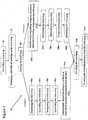
- Figure 1 is flow chart of a process of manufacturing a blade according to an embodiment of the present invention.
- a strip of steel blade stock material from which a plurality of blades are produced, is provided at step 20.
- the steel is provided in a coil form, for example, to render the strip more compact to facilitate handling.
- the steel material is a high carbon steel such as, for example, steel grade C1095 or a low alloy steel (e.g. AISI 4147), although it is contemplated that other types of materials could be used.
- the length of the strip in the coil can be as long as 1 km or more.
- the strip may also be provided in a multiple coils configuration, the multiple coils being welded end to end.
- the dimension of the strip can be selected according to desired dimensions of the blade.
- the strip can have a width of 19 mm and a thickness of 0.6 mm.
- the strip can have other dimensions depending on the intended use of the blade that would be formed from the steel strip.
- the steel strip is provided with a maximum hardness of about 300 HV.
- the steel strip material is delivered to a punch press where a plurality of openings are stamped into the strip to define attachment points employed to retain the blade in a cartridge or onto a blade carrier for utility knife.
- a brand name, logo or other indicia may also be stamped thereon.
- the steel strip is then scored at step 40 to form a plurality of axially spaced score lines, wherein each score line corresponds to a side edge of a respective blade and defines a breaking line for later snapping or cutting the scored strip into a plurality of blades.
- Figure 2 is a schematic representation of a portion of the steel strip 200 that shows the score lines 210.
- the score lines define individual blades 205 that have a trapezoid shape. Other forms and shapes such as parallelogram blades, hook blades, etc. may also be obtained with a selection of an appropriate scoring configuration.
- the scoring and piercing procedures of steps 30 and 40 can be combined into a single stamping operation.
- Option 1 includes hardening the steel strip prior to depositing a hard material (e.g. tungsten carbide) and is represented by steps 50a-90a in Figure 1 .
- Option 2 includes depositing a hard material (e.g. tungsten carbide) prior to hardening the steel strip and is represented by steps 50b-90b. Options 1 and 2 will be described in more detail hereinafter.
- the coil of pressed steel strip of blade stock is then fed at step 50a through a heat treatment line to harden the steel strip material.
- the steel is run off of the coil and passed through a hardening furnace which heats the steel to a temperature above a transition temperature.
- the transition temperature is the temperature at which the structure of the steel changes from a body centred cubic structure, which is stable at room temperature, to a face centred cubic structure known as austenite (austenitic structure), which is stable at elevated temperatures, i.e. above the transition temperature.
- the transition temperature varies depending on the steel material used.
- the heating to harden the steel strip is performed at a temperature between about 800°C and 900°C.
- the transition temperature is approximately 820°C (approximately 1508F).
- the heating to harden the steel strip is performed at a temperature above approximately 820°C.
- the length of the hardening/heating furnace is approximately 26 feet (approximately 8 meters).
- the steel strip travels at a speed approximately between 16 and 22 feet per minute (approximately between 5 and 7 meters per minute).
- cracked ammonia may be used to prevent oxidation and discoloration other gases may be used, such as but not limited to, "a scrubbed endothermic gas” or "molecular sieved exothermic gas.”
- the heating of the steel strip to harden the steel strip is performed for a time period between about 75 and 105 seconds.
- the heat hardened steel strip is quenched.
- the hardened steel strip is passed between liquid cooled conductive blocks disposed above and below the steel strip to quench the steel strip.
- the heat hardened steel strip is passed through water-cooled brass blocks with carbide wear strips in contact with the steel strip to quench the steel. The brass blocks cool the steel strip from the hardening temperature, for example (approximately 820°C), to ambient temperature (approximately 25°C) at a speed above a critical rate of cooling.
- the critical rate of cooling is a rate at which the steel is cooled in order to ensure that the austenitic structure is transformed to martensitic structure.
- a martensitic structure is a body centred tetragonal structure. In the martensitic structure, the steel is highly stressed internally. This internal stress is responsible for the phenomenon known as hardening of the steel. After hardening, the hardness of the steel which was originally less than approximately 300 HV (before heat treatment) becomes approximately 850 HV (approximately 63 HRC).
- the quenching of the steel strip is performed for about 2 to 4 seconds. In another example, a gas or a liquid is used to quench the steel strip.
- the hardened steel strip then passes through a tempering furnace which heats the steel to a temperature between 150°C and 400°C. This process improves the toughness of the blade and reduces the blade hardness to HRc 62 to 55, depending on the tempering temperature selected.
- the length of the tempering furnace is approximately 26 feet (approximately 8 meters).
- the steel strip travels at a speed approximately between 16 and 22 feet per minute (approximately between 5 and 7 meters per minute).
- cracked ammonia may be used to prevent oxidation and discoloration other gases may be used, such as but not limited to a "scrubbed endothermic gas" or "molecular sieved exothermic gas".
- the heating of the strip to temper the strip is performed for a time period between about 75 and 105 seconds.
- the hardened and tempered steel strip is quenched.
- the hardened and tempered steel strip is passed between liquid cooled conductive quench blocks disposed above and below the steel strip to quench the steel strip.
- the heat hardened and tempered steel strip is passed through water-cooled brass blocks with carbide wear strips in contact with the steel strip to quench the steel.
- the brass blocks cool the steel strip from the tempering temperature, for example (approximately 150°C to 400°C), to ambient temperature (approximately 25°C) at a speed above a critical rate of cooling to prevent oxidation of the steel surface.
- the coil of quenched steel strip is then continuously fed at step 90a to a hard material (e.g. tungsten carbide) deposition station that is configured to apply a coating of hard material (e.g. tungsten carbide) to an edge of the steel strip.
- a hard material e.g. tungsten carbide
- the hard material has a hardness that is significantly greater than the steel strip. In one example, the hardness of the hard material is at least 60 Rc. In one example, the hardness of the hard material is in a range from about 70 to 80 Rc.
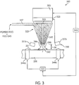
- FIG. 3 this figure is a schematic representation of a deposition station, generally indicated at 300, for depositing a coating of hard material, e.g. tungsten carbide, onto an edge 201 of the moving steel strip 200.
- the deposition station 300 includes a radiation source 305 configured to provide a beam of radiation 355 onto the steel strip 200.
- the deposition station 300 further includes a projection system 325 configured to project and focus the beam of radiation 355 onto a target portion of the steel strip 200.
- the deposition of the hard material (e.g. tungsten carbide/binder) powder takes place (step 50b) before the steel strip is hardened and tempered.
- the hardening and tempering operations are shown in steps 60b-90b and are substantially similar to those of steps 50a-80a. Specifically, after depositing the hard material (e.g. tungsten carbide), the steel strip is hardened at step 60b and quenched at step 70b. Then, the steel strip is tempered at step 80b and quenched at step 90b.
- the radiation source 305 is configured to output a radiation beam with sufficient power and energy to melt the steel strip 200.
- the radiation source is a laser that outputs a beam of radiation in the infrared (IR) range, with a wavelength of a few micrometers.
- IR infrared
- An example of an IR laser that may be used is a CO2 laser with the principal wavelength bands centering around 9.4 and 10.6 micrometers.
- the power of the CO2 laser may be in the range of about a few kWatts, for example between 1 and 8kWatts.. In one example, the power of the CO2 laser is about 6kWatts.
- a laser operating in the ultra-violet (UV) range could also be used in another example such as, for example, a UV laser with a wavelength lower than 400nm. Examples of UV lasers include excimer lasers.
- the beam of radiation 355 outputted by the radiation source 305 is directed to a projection system 325 that is configured to focus the beam onto the edge of the moving steel strip 200.
- the energy of the projected beam 355 that is concentrated on the edge 201 of the steel strip 200 is used to melt the target portion of the steel strip, and when used, the binder within the feed powder 342.
- the projection system 325 may include various types of optical components, such as refractive, reflective, magnetic, electromagnetic, electrostatic or other types of optical components, or any combination thereof, to direct, shape, or control the radiation.
- the projection system 325 may be integral with the radiation source 305.
- the projection system 325 is preferably mounted to a frame that is stationary, although it is contemplated that one or more optical elements of the projection system 325 may be movable to control the shape of the projected radiation beam 355.
- a dispenser or deposition head 320 arranged between the radiation source 305 and the steel strip 200, is configured to supply a mixture 342 of hard material (e.g. tungsten carbide) and a binder element to the thin edge 201 of the steel strip 200.
- the dispenser 320 has a generally hollow shape to allow the beam of radiation 355 to pass there-through.
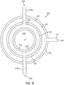
- Figure 4 shows a top view of the dispenser 320 in accordance with an example.
- the dispenser 320 has a generally conical annular shape, although it is contemplated that other shapes (e.g. square, rectangular, oval, polygonal) could be used to dispense the mixture 342.
- the dispenser 320 includes a series of conical annular cavities designed to deliver the powder 342, inert shield gas 361 and laser beam to a single focus point F.
- the shielding gas 361 is Argon.
- the dispenser 320 includes an outer cone 370 and a gas inlet 371 through which the inert shield gas 361 is supplied.
- the dispenser 370 further includes an inner cone 373 and inlets 374a-b through which the mixture 342 is supplied.
- a central cone 375 defines a passage in the dispenser 320 to allow the projected radiation beam 355 to pass therethrough.
- the inner cone 373 is arranged between the central cone 375 and the outer cone 370 and defines a channel 376.
- the inner cone 373 and the outer cone 370 define a channel 377 therebetween to allow the inert shield gas 361 to flow therethrough. It will be appreciated that other arrangements are contemplated. It will also be appreciated that additional or fewer channels may be used to supply the mixture 342 to the steel strip 200.
- the diameter of the periphery 362 of the central cone 375 is selected along with the distance D1 separating the dispenser 320 from the steel strip 200 and the length of the channel 376 such that the particles of the mixture 342 fall under the action of gravity onto a predetermined portion of the steel strip 200. Such predetermined portion generally corresponds to the point of focus F of the beam of radiation 355 onto the steel strip 200.
- the diameter of the inner periphery 362 is also selected in order to allow the radiation beam 355 to pass through the dispenser 320..
- the inner shield gas 361 is configured to form a shield 346 around the mixture 342 at a location near the point of focus F, as shown in Figure 3 .
- the shield 346 provides a protective atmosphere during deposition of the mixture 342 of hard material (e.g. tungsten carbide) in order to prevent oxidation of the steel strip 200.
- the inner shield gas 361 is flushed from the inlet 371 down the channel 377 to the steel strip in a manner that is such that the environment around the melted portion of the steel strip 200 is non-oxidizing.
- the dispenser 320 is fixedly mounted to a frame (not shown) of deposition station 300 and may be either stationary or moveable in at least three directions, e.g. x, y and z directions.
- a benefit of having a moveable dispenser 320 is that the position of the dispenser 320 relative to the steel strip 200 can be accurately controlled.
- Supply of the mixture 342 to the dispenser 320 is effected via the plurality of inlets 374a-b.
- a container (not shown) is used to store the particles of mixture 342.
- the container is arranged to communicate with the plurality of inlets 374a-b via one or more conduits 347 such that the mixture is conveyed to the predetermined portion of the steel strip 200 via the channel 376 under the action of gravity.
- the supply of the mixture 342 be mechanically assisted with, for example, a compressed gas or a mechanical pusher.
- one or more individual nozzles or deposition heads may be used to supply the particles to thin edge 201 of the steel strip 200.
- This configuration is shown in Figure 5 .
- a single power source 505 may be used in conjunction with individual deposition heads or dispensers 510a-f.
- Each individual deposition head 510a-f may be similar to the deposition head 320 shown in Figures 3-4 .
- the radiation beam (e.g. laser beam) provided by the power source 505 is directed to the individual deposition heads 510a-f such that each deposition head supplies its own radiation beam 511 a-f on the thin edge 201 of the steel strip 200.
- Power is individually controlled for each deposition head.
- each deposition head is configured to individually supply its own mixture 512a-f.
- the power source independently supports up to six laser deposition heads. It will be appreciated that additional or fewer deposition heads could be used.
- This configuration is greatly beneficial. Indeed, by independently controlling the power to each deposition head, it is possible to better control the shape of the deposited layer and deposit different compositions (e.g. different mixtures of materials or different compositions of the same mixture) at each deposition edge. In that way, it is possible to have multiple depositions from a single coating process without coiling and re-coating the steel strip 200. In operation, the steel strip 200 moves along the x direction such that various layers can be coated on the thin edge 201 by the different deposition heads 20a-f.
- different compositions e.g. different mixtures of materials or different compositions of the same mixture
- the individual heads 510a-f are positioned along the edge of the thin edge 201 of the steel strip 200.
- the individual deposition heads may be arranged around the predetermined portion of the steel strip 200 where the beam of radiation is focused (point F).
- the one or more individual deposition heads may be stationary or moveable relative to the steel strip 200 in a similar manner as the deposition head or dispenser 320 and compressed air may be used to convey the particles to the steel strip 200.
- the dispenser 320 may also include one or more shutters (not shown) to prevent particles of mixture 342 from exiting the nozzles 360 after completing the deposition process.
- the shutters may be arranged on the inner periphery of the dispenser 320, or within the channels or on the upper portion of the dispenser.
- the steel strip 200 may be moved in at least three directions, x, y and z, relative to the beam of radiation 355 with the aid of an actuator 335.
- the movable steel strip 200 is moved under the radiation beam 355 along the x direction with the use of two rollers 344a-b.
- the two rollers 344a-b can be positioned with the actuator 335.
- One or more separate motors may be used to move the steel strip 200 in the at least three directions, x, y and z.
- actuators that may be used include electric and electromagnetic actuators.
- the position of the steel strip 200 may be controlled with the aid of dedicated electronics and servo control systems. To that effect, a measurement system (not shown) may be used to measure the position of the moving steel strip 200 under the radiation beam 355.
- deposition of the mixture 342 of hard material (e.g. tungsten carbide) and binder element could be carried out in an unprotective environment.
- oxidation of the steel strip 200 will occur at the locations on the blade where the mixture 342 is deposited. The oxidation could then be mechanically or chemically removed after completing the deposition process.
- an in-line polishing process using a wire brushing be applied after deposition of the mixture 342 onto the steel strip 200.
- An in-line measurement system 350 may be used to control the characteristics of the deposited mixture 342 onto the blade perform 10.
- the measurement system 350 is a non-destructive optical system, such as an ellipsometer, that controls the quality/composition and thickness of the film mixture 342.
- the in-line measurement system 350 may include an emitter 351a and a detector 351b.
- the emitter 351a is configured to illuminate the portions of the steel strip 200 with a radiation beam.
- the radiation beam is reflected by the steel strip 200 and then detected by the detector 351b.
- the reflected radiation beam is subsequently analyzed with dedicated instrumentations in order to measure the characteristics of the coating of mixture 342.
- the measurements are performed by the in-line measurement system 350 after completing the deposition process. If the measured characteristics of the steel strip 200 are not within specification, the portion of the steel strip can be marked with a marker to indicate that the final blade should be rejected.
- a controller 345 is used to control the deposition process.
- the controller 345 may be operatively connected to the dispenser 320, the radiation source 305 and the actuator 335.
- the controller 345 may be accessed by an operator to input the illumination settings, control the amount and flow of particles of the mixture 342 in the dispenser 320 and/or the desired positioning of the steel strip 200 during the deposition process.
- the operator can input to the controller 345 the desired composition in each deposition head. It will be appreciated that the positioning of the thin edge 201 of the steel strip 200 under the radiation beam 355, the amount of particles of mixture 342 and the illumination settings of the radiation source 305 may substantially change depending on the geometry and nature of the steel strip 200.
- the thin edge 201 of the steel strip 200 is continuously moved under the radiation beam 355.
- FIG 6 this figure schematically depicts a view of the steel strip 200 during the deposition process.
- the x-direction represents the direction of movement of the steel strip 200 during deposition.
- irradiation of the thin edge 201 of the steel strip 200 creates a weld pool 365 at the point of focus F of the beam of radiation 355.
- Particles 367 of the mixture 342 are released by the dispenser 320 and fall freely within the weld pool under the action of gravity.
- the particles 367 are irradiated and melted by the radiation beam 355 while falling on the steel strip 200. As a result, substantially all the particles 367 are already melted when they reach the weld pool 365.
- the binder element is selected to bind the hard material (e.g. tungsten carbide) to the melted material of the weld pool. All bonding between the particles 367 and the steel strip 200 is achieved by solidification of the hard material (e.g. tungsten carbide)/binder element within the weld pool. This results in a void free deposit of hard material (e.g. tungsten carbide)/binder onto the steel strip 200.
- An example of binder that may be used includes cobalt. However, this is not limiting. It is contemplated that additional binders could be used in other examples.
- the thickness of the deposit is controlled by the particle feed rate, the particle size, the illumination settings of the radiation source (e.g. energy, power, frequency of the radiation pulses) and the rate of passage of the steel strip 200 beneath the focused beam of radiation 355. These parameters are inputted and controlled by the controller 345. The thickness of the deposit is measured by the measurement device 351.
- the illumination settings of the radiation source e.g. energy, power, frequency of the radiation pulses
- the speed of displacement of the steel strip 200 is controlled such that the thickness of the deposit remains within specification at all times.
- the speed of the steel strip 200 may vary depending on the characteristics of the beam of radiation (e.g. wavelength and frequency, energy and power of the pulses), the size of the focus spot and the materials constituting the steel strip 200.
- FIG. 7 shows a schematic representation of the steel strip 200 after deposition of the mixture 342 using a single head or nozzle.
- a single layer 202 of the mixture 342 is coated on the thin edge 201 of the steel strip 200.
- Figure 8 shows a schematic representation of the steel strip 200 after deposition of different mixtures using multiple heads or nozzles. In this example, two heads are used and each head is configured to provide a different mixture composition.
- two layers 203a-b are coated on the thin edge 201 of the steel strip 200. It will be appreciated that more than two layers having the same or a different mixture composition could be coated on the thin edge 201. Further, each of the layers may be coated with a different deposition head or nozzle.
- the deposition of the hard material e.g. tungsten carbide
- the deposition of the hard material could be performed in a similar manner on the opposite side of the blade preform.
- the steel strip 200 is delivered to a grinding machine.
- the steel strip is recoiled and is transferred to a grinding machine for grinding an edge of the strip.
- a relatively shallow angle such as between 10 to 32 degrees is ground onto the edge of the strip. This angle is ground on both sides of the blade, so that the blade is generally symmetrical relative to a longitudinal axis of the blade that bisects the edge, as can be appreciated from Figure 9 .
- the ground angle is measured relative to the longitudinal axis as can also be appreciated from Figure 9 .
- the angle is selected to be shallow to reduce the force that may be required to push the blade through the material it is cutting.
- Figure 9 shows a cross section of an example of a ground edge of a steel strip, according to an example.
- the angle of the ground edge 371 of the steel strip 200 is 22°+-2°.
- the steel strip 200 can be further thermally processed after depositing the hard metal coating at step 90 in accordance with Option 1.
- the steel strip 200 could be again hardened, quenched and tempered in a similar manner as described at steps, 50a, 60a, 70a and 80a.
- the edge of the steel strip may be honed.
- the process of honing puts a second, less acute, angle, such as between 26 to 36 degrees, on top of the ground edge. This deeper honed angle gives a stronger edge than the more shallow ground angle and allows to extend the life span of the cutting edge. As a result the strip has an edge with a double angle.
- the processed steel strip is snapped along the length of the steel strip at each score line to break the steel strip along the score lines to produce a plurality of blades, at step 90.
- An example of an embodiment of a blade obtained according to the manufacturing process of the present invention is shown with its various dimensions in Figure 9 .
- Figure 9 shows a cross section of a blade 205 after grinding and sharpening the steel strip 200
- the blade 205 includes a cutting edge 271 that is mainly made of a hard material (e.g. tungsten carbide) 272 while the remaining portion of the blade is made of the core material constituting the blade 205, denoted as 273 in Figure 9 .
- a hard material e.g. tungsten carbide
- the deposition of tungsten carbide in accordance with an example provides a blade that has a surface of tungsten carbide that is flushed with the remaining surface of the blade.
- the tungsten carbide is welded to the blade so as to form a seamless transition between the tungsten carbide and the core material 273 of the blade.
Landscapes
- Engineering & Computer Science (AREA)
- Mechanical Engineering (AREA)
- Physics & Mathematics (AREA)
- Optics & Photonics (AREA)
- Plasma & Fusion (AREA)
- Chemical & Material Sciences (AREA)
- Materials Engineering (AREA)
- Metallurgy (AREA)
- Organic Chemistry (AREA)
- Life Sciences & Earth Sciences (AREA)
- Forests & Forestry (AREA)
- Other Surface Treatments For Metallic Materials (AREA)
- Welding Or Cutting Using Electron Beams (AREA)
- Polishing Bodies And Polishing Tools (AREA)
- Finish Polishing, Edge Sharpening, And Grinding By Specific Grinding Devices (AREA)
Applications Claiming Priority (2)
| Application Number | Priority Date | Filing Date | Title |
|---|---|---|---|
| US7487508P | 2008-06-23 | 2008-06-23 | |
| US12/486,529 US8505414B2 (en) | 2008-06-23 | 2009-06-17 | Method of manufacturing a blade |
Publications (3)
| Publication Number | Publication Date |
|---|---|
| EP2138263A2 EP2138263A2 (en) | 2009-12-30 |
| EP2138263A3 EP2138263A3 (en) | 2010-02-17 |
| EP2138263B1 true EP2138263B1 (en) | 2017-01-18 |
Family
ID=41198568
Family Applications (1)
| Application Number | Title | Priority Date | Filing Date |
|---|---|---|---|
| EP09163418.8A Active EP2138263B1 (en) | 2008-06-23 | 2009-06-22 | Method of Manufacturing a Blade |
Country Status (4)
| Country | Link |
|---|---|
| US (1) | US8505414B2 (ja) |
| EP (1) | EP2138263B1 (ja) |
| JP (1) | JP5534720B2 (ja) |
| AU (1) | AU2009202494B2 (ja) |
Families Citing this family (32)
| Publication number | Priority date | Publication date | Assignee | Title |
|---|---|---|---|---|
| US8505414B2 (en) * | 2008-06-23 | 2013-08-13 | Stanley Black & Decker, Inc. | Method of manufacturing a blade |
| US8769833B2 (en) * | 2010-09-10 | 2014-07-08 | Stanley Black & Decker, Inc. | Utility knife blade |
| US20120144680A1 (en) | 2010-12-10 | 2012-06-14 | Stanley Black & Decker, Inc. | Cutting blade and method of manufacturing the same |
| EP2855078B1 (en) * | 2012-05-25 | 2020-08-12 | European Space Agency | Multi-wire feeder method for alloy sample formation and additive manufacturing |
| GB201212629D0 (en) * | 2012-07-16 | 2012-08-29 | Prec Engineering Technologies Ltd | A machine tool |
| WO2014063910A1 (en) * | 2012-10-24 | 2014-05-01 | Nv Bekaert Sa | A flat fixed abrasive sawing wire |
| US8884407B2 (en) * | 2012-12-04 | 2014-11-11 | Infineon Technologies Ag | Devices for providing an electrical connection |
| US9833785B2 (en) * | 2012-12-17 | 2017-12-05 | Kooima Company | Method of making a processor disk |
| EP2774714A1 (de) * | 2013-03-06 | 2014-09-10 | Siemens Aktiengesellschaft | Laserauftragsschweißen mit geringem Energieeintrag im Substrat |
| EP2875890A1 (de) * | 2013-11-25 | 2015-05-27 | Böhler-Uddeholm Precision Strip GmbH | Verfahren zur Herstellung eines Vormaterials für ein Zerspanungswerkzeug und entsprechendes Vormaterial |
| EP2875891A1 (de) * | 2013-11-25 | 2015-05-27 | Böhler-Uddeholm Precision Strip GmbH | Verfahren zur Herstellung eines Vormaterials für ein Zerspanungswerkzeug und entsprechendes Vormaterial |
| CN103707024B (zh) * | 2013-12-25 | 2016-04-13 | 安徽日升机械制造有限公司 | 一种高精度纵剪分条刀片的制备方法 |
| CN103639676B (zh) * | 2013-12-25 | 2016-02-10 | 安徽日升机械制造有限公司 | 一种具有高耐磨性和强抗冲击性的月牙剪刀片加工方法 |
| WO2015189600A2 (en) | 2014-06-09 | 2015-12-17 | Ex Scintilla Ltd | Material processing methods and related apparatus |
| JP6092467B2 (ja) * | 2015-03-24 | 2017-03-08 | 技術研究組合次世代3D積層造形技術総合開発機構 | 加工ノズル、加工ヘッド、加工装置 |
| US10648051B2 (en) * | 2015-04-24 | 2020-05-12 | Kondex Corporation | Reciprocating cutting blade with cladding |
| GB2540476A (en) * | 2015-07-15 | 2017-01-18 | C4 Carbides Ltd | Improvements in or relating to tool blades and their manufacture |
| GB2540385B (en) * | 2015-07-15 | 2017-10-11 | C4 Carbides Ltd | Improvements in or relating to tool blades and their manufacture |
| CN107486690B (zh) * | 2015-08-14 | 2019-05-17 | 安徽省凌锋冶金机械有限公司 | 一种圆盘剪刀片的制造方法 |
| US10688596B2 (en) * | 2015-12-18 | 2020-06-23 | Illinois Tool Works Inc. | Wire manufactured by additive manufacturing methods |
| JP7099800B2 (ja) * | 2016-07-29 | 2022-07-12 | 三菱マテリアル株式会社 | 複合部材およびこれからなる切削工具 |
| JP6761596B2 (ja) * | 2016-07-29 | 2020-09-30 | 三菱マテリアル株式会社 | 複合材料からなる切削工具 |
| US10321633B1 (en) * | 2016-11-10 | 2019-06-18 | Ronald J. Kile | Threshing bars with reinforced spikes and cutting blades |
| US10457035B2 (en) | 2017-03-07 | 2019-10-29 | General Electric Company | Apparatuses and systems for net shape manufacturing |
| CN107130239B (zh) * | 2017-06-28 | 2019-12-31 | 苏州大学 | 局部气氛保护金属或合金激光熔覆成形的方法 |
| US10994379B2 (en) * | 2019-01-04 | 2021-05-04 | George H. Lambert | Laser deposition process for a self sharpening knife cutting edge |
| JP7227826B2 (ja) * | 2019-03-29 | 2023-02-22 | 株式会社フジクラ | 光ファイバカッタ用刃体の製造方法 |
| DE102019117796A1 (de) * | 2019-07-02 | 2021-01-07 | WIKUS-Sägenfabrik Wilhelm H. Kullmann GmbH & Co. KG | Zerspanungswerkzeug mit Pufferpartikeln |
| CN111673193B (zh) * | 2020-06-15 | 2021-04-23 | 浙江津灿工贸有限公司 | 一种电锯用锯齿平面加工机构 |
| CN112123285B (zh) * | 2020-09-09 | 2021-12-24 | 阳江市睿盈科技有限公司 | 一种焊接刀具及其制作方法 |
| US20220347876A1 (en) * | 2021-05-03 | 2022-11-03 | The Gillette Company Llc | Metals for razor blade applications |
| WO2023220770A1 (en) * | 2022-05-17 | 2023-11-23 | Commonwealth Scientific And Industrial Research Organisation | Process of forming a cutting tool with additively deposited cutting edge |
Family Cites Families (110)
| Publication number | Priority date | Publication date | Assignee | Title |
|---|---|---|---|---|
| US476531A (en) * | 1892-06-07 | Thomas a | ||
| US1639335A (en) * | 1924-06-24 | 1927-08-16 | Autostrop Patents Corp | Blade holder |
| US1823976A (en) * | 1927-03-11 | 1931-09-22 | Gillette Safety Razor Co | Safety razor |
| US1855478A (en) * | 1927-03-12 | 1932-04-26 | Gillette Safety Razor Co | Safety razor |
| US1849919A (en) * | 1929-02-11 | 1932-03-15 | Gillette Safety Razor Co | Safety razor |
| US1821578A (en) * | 1929-04-25 | 1931-09-01 | Fedco System Inc | Process of making identification plates |
| US2073501A (en) * | 1932-10-08 | 1937-03-09 | Gillette Safety Razor Co | Coloring and hardening steel |
| US2137817A (en) * | 1934-03-30 | 1938-11-22 | Windsor Mfg Co | Process of coloring metal |
| US2032963A (en) * | 1934-09-29 | 1936-03-03 | Rockwell W S Co | Method of coloring and hardening steel |
| US2244053A (en) * | 1935-06-22 | 1941-06-03 | Gregory J Comstock | Hard cemented carbide composite |
| US2073502A (en) * | 1936-04-08 | 1937-03-09 | Gillette Safety Razor Co | Safety razor blade and blade strip |
| US2131505A (en) * | 1938-08-16 | 1938-09-27 | Henry M Garsson | Treating steel |
| US2326774A (en) * | 1939-07-11 | 1943-08-17 | Benjamin H Freedman | Safety razor |
| US2964420A (en) | 1955-06-14 | 1960-12-13 | Union Carbide Corp | Refractory coated body |
| US3283117A (en) * | 1965-04-22 | 1966-11-01 | Philip Morris Inc | Method for coating cutting edges of sharpened instruments |
| US3480483A (en) * | 1965-05-06 | 1969-11-25 | Wilkinson Sword Ltd | Razor blades and methods of manufacture thereof |
| GB1147393A (en) * | 1966-02-14 | 1969-04-02 | Wilkinson Sword Ltd | Improvements in or relating to the marking of metal surfaces by electrolytic action |
| GB1149781A (en) | 1966-06-09 | 1969-04-23 | Gillette Industries Ltd | Improvements in or relating to razor blades |
| US3490314A (en) * | 1967-03-01 | 1970-01-20 | Gillette Co | Cutting instruments |
| US3496973A (en) * | 1967-04-12 | 1970-02-24 | Robert L Ballard | Cutting tool edge construction |
| US3652342A (en) * | 1967-06-07 | 1972-03-28 | Gillette Co | Razor blades and processes for the preparation thereof |
| US3754329A (en) * | 1967-11-06 | 1973-08-28 | Warner Lambert Co | Razor blade with rf sputtered coating |
| US3664884A (en) * | 1968-03-11 | 1972-05-23 | Concept Research Corp | Method of coloring metals by the application of heat |
| US3916523A (en) * | 1969-09-29 | 1975-11-04 | Warner Lambert Co | Coated razor blade |
| BR7102060D0 (pt) * | 1970-04-17 | 1973-04-05 | Wilkinson Sword Ltd | Lamina de barbear e processo para a fabricacao da mesma |
| US3751283A (en) * | 1971-03-08 | 1973-08-07 | Remington Arms Co Inc | Armored metal tools and production thereof |
| US4015100A (en) * | 1974-01-07 | 1977-03-29 | Avco Everett Research Laboratory, Inc. | Surface modification |
| US3952180A (en) * | 1974-12-04 | 1976-04-20 | Avco Everett Research Laboratory, Inc. | Cladding |
| US4004042A (en) * | 1975-03-07 | 1977-01-18 | Sirius Corporation | Method for applying a wear and impact resistant coating |
| GB2052566B (en) * | 1979-03-30 | 1982-12-15 | Rolls Royce | Laser aplication of hard surface alloy |
| US4323756A (en) * | 1979-10-29 | 1982-04-06 | United Technologies Corporation | Method for fabricating articles by sequential layer deposition |
| US4299860A (en) * | 1980-09-08 | 1981-11-10 | The United States Of America As Represented By The Secretary Of The Navy | Surface hardening by particle injection into laser melted surface |
| DE3202697A1 (de) * | 1982-01-28 | 1983-08-04 | Kapp & Co Werkzeugmaschinenfabrik, 8630 Coburg | Verfahren und vorrichtung zum feinprofilieren von mit superharten werkstoffen beschichteten werkzeugen |
| JPS58177238A (ja) * | 1982-04-05 | 1983-10-17 | Toshiba Corp | 刃物の製造方法 |
| DE3216456A1 (de) | 1982-05-03 | 1983-11-03 | Robert Bosch Gmbh, 7000 Stuttgart | Verfahren zum einbetten von hartstoffen in die oberflaeche von spanabhebenden werkzeugen |
| SE437682B (sv) | 1982-10-13 | 1985-03-11 | Inventing Ab | Sett och anleggning for att applicera en notningsbestendig beleggning pa ett tunnt metalliskt, bandformigt berarmaterial |
| US4547649A (en) * | 1983-03-04 | 1985-10-15 | The Babcock & Wilcox Company | Method for superficial marking of zirconium and certain other metals |
| CA1265209A (en) * | 1984-02-17 | 1990-01-30 | Robert Langen | Process to remove contaminants, particularly rust/from metallic surfaces |
| IT1179061B (it) * | 1984-08-20 | 1987-09-16 | Fiat Auto Spa | Procedimento per l'effettuazione di un trattamento su pezzi metallici con l'aggiunta di un materiale d'apporto e con l'impiego di un laser di potenza |
| US4653373A (en) * | 1986-01-08 | 1987-03-31 | Gerber Scientific Inc. | Knife blade and method for making same |
| JPH0649228B2 (ja) * | 1986-03-25 | 1994-06-29 | 大同特殊鋼株式会社 | 工具の製造方法 |
| US6083570A (en) * | 1987-03-31 | 2000-07-04 | Lemelson; Jerome H. | Synthetic diamond coatings with intermediate amorphous metal bonding layers and methods of applying such coatings |
| US4724299A (en) * | 1987-04-15 | 1988-02-09 | Quantum Laser Corporation | Laser spray nozzle and method |
| US5204167A (en) * | 1989-02-23 | 1993-04-20 | Toshiba Tungaloy Co., Ltd. | Diamond-coated sintered body excellent in adhesion and process for preparing the same |
| US4981756A (en) * | 1989-03-21 | 1991-01-01 | Vac-Tec Systems, Inc. | Method for coated surgical instruments and tools |
| US5066553A (en) * | 1989-04-12 | 1991-11-19 | Mitsubishi Metal Corporation | Surface-coated tool member of tungsten carbide based cemented carbide |
| US5368947A (en) * | 1991-08-12 | 1994-11-29 | The Penn State Research Foundation | Method of producing a slip-resistant substrate by depositing raised, bead-like configurations of a compatible material at select locations thereon, and a substrate including same |
| FR2685922B1 (fr) * | 1992-01-07 | 1995-03-24 | Strasbourg Elec | Buse coaxiale de traitement superficiel sous irradiation laser, avec apport de materiaux sous forme de poudre. |
| US5295305B1 (en) * | 1992-02-13 | 1996-08-13 | Gillette Co | Razor blade technology |
| US5304771A (en) * | 1992-02-18 | 1994-04-19 | D. A. Griffin Corporation | Apparatus for precisely metering powder for welding |
| US5476531A (en) | 1992-02-20 | 1995-12-19 | The Dow Chemical Company | Rhenium-bound tungsten carbide composites |
| GB9208952D0 (en) | 1992-04-24 | 1992-06-10 | Mcphersons Ltd | Knife blades |
| US5453329A (en) * | 1992-06-08 | 1995-09-26 | Quantum Laser Corporation | Method for laser cladding thermally insulated abrasive particles to a substrate, and clad substrate formed thereby |
| US5449536A (en) * | 1992-12-18 | 1995-09-12 | United Technologies Corporation | Method for the application of coatings of oxide dispersion strengthened metals by laser powder injection |
| JPH06226554A (ja) * | 1993-02-09 | 1994-08-16 | N T Kk | 刃体の製造方法 |
| JPH06304820A (ja) * | 1993-04-23 | 1994-11-01 | Matsushita Electric Works Ltd | 刃物およびその製造方法 |
| US5620754A (en) * | 1994-01-21 | 1997-04-15 | Qqc, Inc. | Method of treating and coating substrates |
| US5731046A (en) * | 1994-01-18 | 1998-03-24 | Qqc, Inc. | Fabrication of diamond and diamond-like carbon coatings |
| US5477026A (en) | 1994-01-27 | 1995-12-19 | Chromalloy Gas Turbine Corporation | Laser/powdered metal cladding nozzle |
| DE4437911A1 (de) | 1994-10-22 | 1996-04-25 | Zwilling J A Henckels Ag | Messer und Verfahren zur Herstellung eines Messers |
| US5486676A (en) * | 1994-11-14 | 1996-01-23 | General Electric Company | Coaxial single point powder feed nozzle |
| US5543183A (en) * | 1995-02-17 | 1996-08-06 | General Atomics | Chromium surface treatment of nickel-based substrates |
| GB9506494D0 (en) * | 1995-03-30 | 1995-05-17 | Mcphersons Ltd | Knife blades |
| US5722803A (en) * | 1995-07-14 | 1998-03-03 | Kennametal Inc. | Cutting tool and method of making the cutting tool |
| US5728434A (en) | 1995-08-08 | 1998-03-17 | Pacific/Hoe Saw And Knife Company | Method of applying a wear-resistant coating on a thin, metallic strip-shaped carrier |
| US5837960A (en) * | 1995-08-14 | 1998-11-17 | The Regents Of The University Of California | Laser production of articles from powders |
| EA000943B1 (ru) * | 1995-10-05 | 2000-06-26 | Блц Байеришес Лазерцентрум Гемайннютциге Форшунгсгезелльшафт Мбх | Способ изготовления режущего инструмента |
| US5724868A (en) * | 1996-01-11 | 1998-03-10 | Buck Knives, Inc. | Method of making knife with cutting performance |
| US6293020B1 (en) * | 1997-02-14 | 2001-09-25 | Nitinol Technologies, Inc. | Cutting instruments |
| US5736709A (en) * | 1996-08-12 | 1998-04-07 | Armco Inc. | Descaling metal with a laser having a very short pulse width and high average power |
| US5906053A (en) * | 1997-03-14 | 1999-05-25 | Fisher Barton, Inc. | Rotary cutting blade having a laser hardened cutting edge and a method for making the same with a laser |
| CA2207579A1 (fr) * | 1997-05-28 | 1998-11-28 | Paul Caron | Piece frittee a surface anti-abrasive et procede pour sa realisation |
| US6146476A (en) * | 1999-02-08 | 2000-11-14 | Alvord-Polk, Inc. | Laser-clad composite cutting tool and method |
| US6396025B1 (en) * | 1999-07-01 | 2002-05-28 | Aeromet Corporation | Powder feed nozzle for laser welding |
| DE19931948B4 (de) * | 1999-07-09 | 2004-11-11 | Zwilling J. A. Henckels Ag | Verfahren zur Herstellung einer Klinge eines Schneidwerkzeuges und damit hergestelltes Erzeugnis |
| US6534745B1 (en) * | 1999-09-27 | 2003-03-18 | Mathew T. J. Lowney | Nozzle particularly suited to direct metal deposition |
| US6756561B2 (en) * | 1999-09-30 | 2004-06-29 | National Research Council Of Canada | Laser consolidation apparatus for manufacturing precise structures |
| JP4741056B2 (ja) | 2000-06-05 | 2011-08-03 | 株式会社貝印刃物開発センター | 刃部材及びその刃先の製造方法 |
| US6497772B1 (en) | 2000-09-27 | 2002-12-24 | Molecular Metallurgy, Inc. | Surface treatment for improved hardness and corrosion resistance |
| US6805944B2 (en) * | 2001-03-26 | 2004-10-19 | Mitsubishi Materials Corporation | Coated cemented carbide cutting tool |
| US7140113B2 (en) | 2001-04-17 | 2006-11-28 | Lazorblades, Inc. | Ceramic blade and production method therefor |
| AT411654B (de) * | 2001-06-25 | 2004-04-26 | Boehler Ybbstal Band Gmbh & Co | Verfahren zur herstellung eines zerspanungswerkzeuges |
| US7712222B2 (en) * | 2001-07-26 | 2010-05-11 | Irwin Industrial Tool Company | Composite utility blade, and method of making such a blade |
| US6701627B2 (en) * | 2001-07-26 | 2004-03-09 | American Saw & Mfg. Company, Inc. | Composite utility knife blade |
| EP1340583A1 (en) * | 2002-02-20 | 2003-09-03 | ALSTOM (Switzerland) Ltd | Method of controlled remelting of or laser metal forming on the surface of an article |
| US6617271B1 (en) * | 2002-03-19 | 2003-09-09 | Vladimir Yurievich Kodash | Tungsten carbide cutting tool materials |
| US6857255B1 (en) * | 2002-05-16 | 2005-02-22 | Fisher-Barton Llc | Reciprocating cutting blade having laser-hardened cutting edges and a method for making the same with a laser |
| KR101056487B1 (ko) * | 2002-08-28 | 2011-08-11 | 더 피.오.엠. 그룹 | 다층 디엠디 프로세스용 부품 기하학적 독립 실시간 폐쇄루프 용접 풀 온도 제어 시스템 |
| US7139633B2 (en) * | 2002-08-29 | 2006-11-21 | Jyoti Mazumder | Method of fabricating composite tooling using closed-loop direct-metal deposition |
| EP1396556A1 (en) * | 2002-09-06 | 2004-03-10 | ALSTOM (Switzerland) Ltd | Method for controlling the microstructure of a laser metal formed hard layer |
| JP4204293B2 (ja) | 2002-09-30 | 2009-01-07 | アイシン軽金属株式会社 | アルミニウム合金表面への画像形成方法 |
| US7111376B2 (en) * | 2003-01-13 | 2006-09-26 | The Stanley Works | Tool with inserted blade members |
| EP1454705A1 (de) * | 2003-03-05 | 2004-09-08 | Trumpf Werkzeugmaschinen GmbH + Co. KG | Verfahren zur thermischen Bearbeitung eines Werkstückes mit einem Werkstückgrundkörper aus Metall, insbesondere aus Aluminium |
| DE10320652A1 (de) * | 2003-05-07 | 2004-12-02 | Kennametal Widia Gmbh & Co.Kg | Werkzeug, insbesondere Schneidwerkzeug und Verfahren zur CVD-Abscheidung einer zweiphasigen Schicht auf einem Substratkörper |
| SE527180C2 (sv) | 2003-08-12 | 2006-01-17 | Sandvik Intellectual Property | Rakel- eller schaberblad med nötningsbeständigt skikt samt metod för tillverkning därav |
| US6995334B1 (en) * | 2003-08-25 | 2006-02-07 | Southern Methodist University | System and method for controlling the size of the molten pool in laser-based additive manufacturing |
| US20050056628A1 (en) * | 2003-09-16 | 2005-03-17 | Yiping Hu | Coaxial nozzle design for laser cladding/welding process |
| JP4299157B2 (ja) * | 2004-02-03 | 2009-07-22 | トヨタ自動車株式会社 | 粉末金属肉盛ノズル |
| WO2005089995A1 (fr) * | 2004-02-18 | 2005-09-29 | Societe D'exploitation Tarrerias Bonjean | Procede de fabrication d'une lame tranchante et lame tranchante |
| US7673541B2 (en) * | 2004-06-03 | 2010-03-09 | The Gillette Company | Colored razor blades |
| US20060049153A1 (en) * | 2004-09-08 | 2006-03-09 | Cahoon Christopher L | Dual feed laser welding system |
| US7259353B2 (en) * | 2004-09-30 | 2007-08-21 | Honeywell International, Inc. | Compact coaxial nozzle for laser cladding |
| US7284461B2 (en) * | 2004-12-16 | 2007-10-23 | The Gillette Company | Colored razor blades |
| US8322253B2 (en) * | 2005-07-08 | 2012-12-04 | Stanley Black & Decker, Inc. | Method of manufacturing a utility knife blade having an induction hardened cutting edge |
| US20070131060A1 (en) | 2005-12-14 | 2007-06-14 | The Gillette Company | Automated control of razor blade colorization |
| ATE500725T1 (de) | 2006-05-10 | 2011-03-15 | Fraunhofer Ges Forschung | Schneidevorrichtung |
| EP1953004B1 (de) | 2007-01-24 | 2012-03-07 | KUM Limited | Spitzerklinge |
| US20080189957A1 (en) * | 2007-02-12 | 2008-08-14 | The Stanley Works | Bi-metal chisel blade |
| US8505414B2 (en) * | 2008-06-23 | 2013-08-13 | Stanley Black & Decker, Inc. | Method of manufacturing a blade |
| US8592711B2 (en) * | 2009-10-01 | 2013-11-26 | George H. Lambert | Apparatus and method of electronically impregnating a wear-resistant cutting edge |
-
2009
- 2009-06-17 US US12/486,529 patent/US8505414B2/en not_active Expired - Fee Related
- 2009-06-22 AU AU2009202494A patent/AU2009202494B2/en not_active Ceased
- 2009-06-22 EP EP09163418.8A patent/EP2138263B1/en active Active
- 2009-06-23 JP JP2009148697A patent/JP5534720B2/ja not_active Expired - Fee Related
Non-Patent Citations (1)
| Title |
|---|
| None * |
Also Published As
| Publication number | Publication date |
|---|---|
| AU2009202494A1 (en) | 2010-01-14 |
| JP2010000596A (ja) | 2010-01-07 |
| EP2138263A2 (en) | 2009-12-30 |
| AU2009202494B2 (en) | 2014-08-14 |
| US20090314136A1 (en) | 2009-12-24 |
| EP2138263A3 (en) | 2010-02-17 |
| US8505414B2 (en) | 2013-08-13 |
| JP5534720B2 (ja) | 2014-07-02 |
Similar Documents
| Publication | Publication Date | Title |
|---|---|---|
| EP2138263B1 (en) | Method of Manufacturing a Blade | |
| US9393984B2 (en) | Utility knife blade | |
| CN202480108U (zh) | 刀片 | |
| US20140339881A1 (en) | Cutter Insert Gum Modification Method And Appratus | |
| US9238277B2 (en) | Cutting/polishing tool and manufacturing method thereof | |
| US7827883B1 (en) | Cutting die and method of forming | |
| US20180229332A1 (en) | Foil-based additive manufacturing system and method | |
| EP3459675A1 (en) | Laser cutting and machining method for plated steel plate, laser cut-and-machined product, thermal cutting and machining method, thermal cut-and-machined product, surface-treated steel plate, laser cutting method, and laser machining head | |
| US20150336218A1 (en) | Method for regenerating and/or increasing the durability of a mill roll | |
| AU781334B2 (en) | Method for producing a surface-alloyed cylindrical, partially cylindrical or hollow cylindrical component and a device for carrying out said method | |
| Hu et al. | Development of a new laser cladding process for manufacturing cutting and stamping dies | |
| CN114555278A (zh) | 熔覆的工具和制造熔覆的工具的方法 | |
| JPH0770964A (ja) | 紙パルプの繊維離解化又は精製用プレート及びその製造方法 | |
| WO2018089080A1 (en) | Foil-based additive manufacturing system and method | |
| CA2451514A1 (en) | Cutting tools in band form | |
| US7401537B1 (en) | Cutter insert gum modification method and apparatus | |
| US20250353114A1 (en) | Method for coating metal workpieces | |
| Klimpel et al. | New developments in the process of the laser powder surfacing | |
| CN120700483A (zh) | 基于激光雕刻和熔覆技术的双色表面图案成型方法 |
Legal Events
| Date | Code | Title | Description |
|---|---|---|---|
| PUAI | Public reference made under article 153(3) epc to a published international application that has entered the european phase |
Free format text: ORIGINAL CODE: 0009012 |
|
| AK | Designated contracting states |
Kind code of ref document: A2 Designated state(s): AT BE BG CH CY CZ DE DK EE ES FI FR GB GR HR HU IE IS IT LI LT LU LV MC MK MT NL NO PL PT RO SE SI SK TR |
|
| PUAL | Search report despatched |
Free format text: ORIGINAL CODE: 0009013 |
|
| AK | Designated contracting states |
Kind code of ref document: A3 Designated state(s): AT BE BG CH CY CZ DE DK EE ES FI FR GB GR HR HU IE IS IT LI LT LU LV MC MK MT NL NO PL PT RO SE SI SK TR |
|
| AX | Request for extension of the european patent |
Extension state: AL BA RS |
|
| RIC1 | Information provided on ipc code assigned before grant |
Ipc: B21D 53/64 20060101ALI20100108BHEP Ipc: B23D 65/00 20060101ALI20100108BHEP Ipc: B23P 15/28 20060101AFI20091030BHEP Ipc: B23P 15/40 20060101ALI20100108BHEP |
|
| 17P | Request for examination filed |
Effective date: 20100805 |
|
| 17Q | First examination report despatched |
Effective date: 20101012 |
|
| RAP1 | Party data changed (applicant data changed or rights of an application transferred) |
Owner name: STANLEY BLACK & DECKER, INC. |
|
| GRAP | Despatch of communication of intention to grant a patent |
Free format text: ORIGINAL CODE: EPIDOSNIGR1 |
|
| STAA | Information on the status of an ep patent application or granted ep patent |
Free format text: STATUS: GRANT OF PATENT IS INTENDED |
|
| GRAS | Grant fee paid |
Free format text: ORIGINAL CODE: EPIDOSNIGR3 |
|
| INTG | Intention to grant announced |
Effective date: 20161117 |
|
| GRAA | (expected) grant |
Free format text: ORIGINAL CODE: 0009210 |
|
| STAA | Information on the status of an ep patent application or granted ep patent |
Free format text: STATUS: THE PATENT HAS BEEN GRANTED |
|
| AK | Designated contracting states |
Kind code of ref document: B1 Designated state(s): AT BE BG CH CY CZ DE DK EE ES FI FR GB GR HR HU IE IS IT LI LT LU LV MC MK MT NL NO PL PT RO SE SI SK TR |
|
| REG | Reference to a national code |
Ref country code: GB Ref legal event code: FG4D |
|
| REG | Reference to a national code |
Ref country code: CH Ref legal event code: EP |
|
| REG | Reference to a national code |
Ref country code: AT Ref legal event code: REF Ref document number: 862620 Country of ref document: AT Kind code of ref document: T Effective date: 20170215 |
|
| REG | Reference to a national code |
Ref country code: IE Ref legal event code: FG4D |
|
| REG | Reference to a national code |
Ref country code: DE Ref legal event code: R096 Ref document number: 602009043805 Country of ref document: DE |
|
| REG | Reference to a national code |
Ref country code: FR Ref legal event code: PLFP Year of fee payment: 9 |
|
| REG | Reference to a national code |
Ref country code: NL Ref legal event code: MP Effective date: 20170118 |
|
| REG | Reference to a national code |
Ref country code: LT Ref legal event code: MG4D |
|
| REG | Reference to a national code |
Ref country code: AT Ref legal event code: MK05 Ref document number: 862620 Country of ref document: AT Kind code of ref document: T Effective date: 20170118 |
|
| PG25 | Lapsed in a contracting state [announced via postgrant information from national office to epo] |
Ref country code: NL Free format text: LAPSE BECAUSE OF FAILURE TO SUBMIT A TRANSLATION OF THE DESCRIPTION OR TO PAY THE FEE WITHIN THE PRESCRIBED TIME-LIMIT Effective date: 20170118 |
|
| PG25 | Lapsed in a contracting state [announced via postgrant information from national office to epo] |
Ref country code: NO Free format text: LAPSE BECAUSE OF FAILURE TO SUBMIT A TRANSLATION OF THE DESCRIPTION OR TO PAY THE FEE WITHIN THE PRESCRIBED TIME-LIMIT Effective date: 20170418 Ref country code: FI Free format text: LAPSE BECAUSE OF FAILURE TO SUBMIT A TRANSLATION OF THE DESCRIPTION OR TO PAY THE FEE WITHIN THE PRESCRIBED TIME-LIMIT Effective date: 20170118 Ref country code: IS Free format text: LAPSE BECAUSE OF FAILURE TO SUBMIT A TRANSLATION OF THE DESCRIPTION OR TO PAY THE FEE WITHIN THE PRESCRIBED TIME-LIMIT Effective date: 20170518 Ref country code: GR Free format text: LAPSE BECAUSE OF FAILURE TO SUBMIT A TRANSLATION OF THE DESCRIPTION OR TO PAY THE FEE WITHIN THE PRESCRIBED TIME-LIMIT Effective date: 20170419 Ref country code: LT Free format text: LAPSE BECAUSE OF FAILURE TO SUBMIT A TRANSLATION OF THE DESCRIPTION OR TO PAY THE FEE WITHIN THE PRESCRIBED TIME-LIMIT Effective date: 20170118 Ref country code: HR Free format text: LAPSE BECAUSE OF FAILURE TO SUBMIT A TRANSLATION OF THE DESCRIPTION OR TO PAY THE FEE WITHIN THE PRESCRIBED TIME-LIMIT Effective date: 20170118 |
|
| PG25 | Lapsed in a contracting state [announced via postgrant information from national office to epo] |
Ref country code: AT Free format text: LAPSE BECAUSE OF FAILURE TO SUBMIT A TRANSLATION OF THE DESCRIPTION OR TO PAY THE FEE WITHIN THE PRESCRIBED TIME-LIMIT Effective date: 20170118 Ref country code: BG Free format text: LAPSE BECAUSE OF FAILURE TO SUBMIT A TRANSLATION OF THE DESCRIPTION OR TO PAY THE FEE WITHIN THE PRESCRIBED TIME-LIMIT Effective date: 20170418 Ref country code: PL Free format text: LAPSE BECAUSE OF FAILURE TO SUBMIT A TRANSLATION OF THE DESCRIPTION OR TO PAY THE FEE WITHIN THE PRESCRIBED TIME-LIMIT Effective date: 20170118 Ref country code: ES Free format text: LAPSE BECAUSE OF FAILURE TO SUBMIT A TRANSLATION OF THE DESCRIPTION OR TO PAY THE FEE WITHIN THE PRESCRIBED TIME-LIMIT Effective date: 20170118 Ref country code: SE Free format text: LAPSE BECAUSE OF FAILURE TO SUBMIT A TRANSLATION OF THE DESCRIPTION OR TO PAY THE FEE WITHIN THE PRESCRIBED TIME-LIMIT Effective date: 20170118 Ref country code: LV Free format text: LAPSE BECAUSE OF FAILURE TO SUBMIT A TRANSLATION OF THE DESCRIPTION OR TO PAY THE FEE WITHIN THE PRESCRIBED TIME-LIMIT Effective date: 20170118 Ref country code: PT Free format text: LAPSE BECAUSE OF FAILURE TO SUBMIT A TRANSLATION OF THE DESCRIPTION OR TO PAY THE FEE WITHIN THE PRESCRIBED TIME-LIMIT Effective date: 20170518 |
|
| REG | Reference to a national code |
Ref country code: DE Ref legal event code: R097 Ref document number: 602009043805 Country of ref document: DE |
|
| PG25 | Lapsed in a contracting state [announced via postgrant information from national office to epo] |
Ref country code: RO Free format text: LAPSE BECAUSE OF FAILURE TO SUBMIT A TRANSLATION OF THE DESCRIPTION OR TO PAY THE FEE WITHIN THE PRESCRIBED TIME-LIMIT Effective date: 20170118 Ref country code: CZ Free format text: LAPSE BECAUSE OF FAILURE TO SUBMIT A TRANSLATION OF THE DESCRIPTION OR TO PAY THE FEE WITHIN THE PRESCRIBED TIME-LIMIT Effective date: 20170118 Ref country code: SK Free format text: LAPSE BECAUSE OF FAILURE TO SUBMIT A TRANSLATION OF THE DESCRIPTION OR TO PAY THE FEE WITHIN THE PRESCRIBED TIME-LIMIT Effective date: 20170118 Ref country code: EE Free format text: LAPSE BECAUSE OF FAILURE TO SUBMIT A TRANSLATION OF THE DESCRIPTION OR TO PAY THE FEE WITHIN THE PRESCRIBED TIME-LIMIT Effective date: 20170118 |
|
| PLBE | No opposition filed within time limit |
Free format text: ORIGINAL CODE: 0009261 |
|
| STAA | Information on the status of an ep patent application or granted ep patent |
Free format text: STATUS: NO OPPOSITION FILED WITHIN TIME LIMIT |
|
| PG25 | Lapsed in a contracting state [announced via postgrant information from national office to epo] |
Ref country code: DK Free format text: LAPSE BECAUSE OF FAILURE TO SUBMIT A TRANSLATION OF THE DESCRIPTION OR TO PAY THE FEE WITHIN THE PRESCRIBED TIME-LIMIT Effective date: 20170118 |
|
| 26N | No opposition filed |
Effective date: 20171019 |
|
| PG25 | Lapsed in a contracting state [announced via postgrant information from national office to epo] |
Ref country code: MC Free format text: LAPSE BECAUSE OF FAILURE TO SUBMIT A TRANSLATION OF THE DESCRIPTION OR TO PAY THE FEE WITHIN THE PRESCRIBED TIME-LIMIT Effective date: 20170118 |
|
| REG | Reference to a national code |
Ref country code: CH Ref legal event code: PL |
|
| PG25 | Lapsed in a contracting state [announced via postgrant information from national office to epo] |
Ref country code: SI Free format text: LAPSE BECAUSE OF FAILURE TO SUBMIT A TRANSLATION OF THE DESCRIPTION OR TO PAY THE FEE WITHIN THE PRESCRIBED TIME-LIMIT Effective date: 20170118 |
|
| REG | Reference to a national code |
Ref country code: IE Ref legal event code: MM4A |
|
| PG25 | Lapsed in a contracting state [announced via postgrant information from national office to epo] |
Ref country code: LI Free format text: LAPSE BECAUSE OF NON-PAYMENT OF DUE FEES Effective date: 20170630 Ref country code: LU Free format text: LAPSE BECAUSE OF NON-PAYMENT OF DUE FEES Effective date: 20170622 Ref country code: CH Free format text: LAPSE BECAUSE OF NON-PAYMENT OF DUE FEES Effective date: 20170630 Ref country code: IE Free format text: LAPSE BECAUSE OF NON-PAYMENT OF DUE FEES Effective date: 20170622 |
|
| REG | Reference to a national code |
Ref country code: BE Ref legal event code: MM Effective date: 20170630 |
|
| REG | Reference to a national code |
Ref country code: FR Ref legal event code: PLFP Year of fee payment: 10 |
|
| PG25 | Lapsed in a contracting state [announced via postgrant information from national office to epo] |
Ref country code: BE Free format text: LAPSE BECAUSE OF NON-PAYMENT OF DUE FEES Effective date: 20170630 |
|
| PG25 | Lapsed in a contracting state [announced via postgrant information from national office to epo] |
Ref country code: MT Free format text: LAPSE BECAUSE OF NON-PAYMENT OF DUE FEES Effective date: 20170622 |
|
| PG25 | Lapsed in a contracting state [announced via postgrant information from national office to epo] |
Ref country code: HU Free format text: LAPSE BECAUSE OF FAILURE TO SUBMIT A TRANSLATION OF THE DESCRIPTION OR TO PAY THE FEE WITHIN THE PRESCRIBED TIME-LIMIT; INVALID AB INITIO Effective date: 20090622 |
|
| PGFP | Annual fee paid to national office [announced via postgrant information from national office to epo] |
Ref country code: IT Payment date: 20190620 Year of fee payment: 11 |
|
| PG25 | Lapsed in a contracting state [announced via postgrant information from national office to epo] |
Ref country code: CY Free format text: LAPSE BECAUSE OF NON-PAYMENT OF DUE FEES Effective date: 20170118 |
|
| PG25 | Lapsed in a contracting state [announced via postgrant information from national office to epo] |
Ref country code: MK Free format text: LAPSE BECAUSE OF FAILURE TO SUBMIT A TRANSLATION OF THE DESCRIPTION OR TO PAY THE FEE WITHIN THE PRESCRIBED TIME-LIMIT Effective date: 20170118 |
|
| PG25 | Lapsed in a contracting state [announced via postgrant information from national office to epo] |
Ref country code: TR Free format text: LAPSE BECAUSE OF FAILURE TO SUBMIT A TRANSLATION OF THE DESCRIPTION OR TO PAY THE FEE WITHIN THE PRESCRIBED TIME-LIMIT Effective date: 20170118 |
|
| PG25 | Lapsed in a contracting state [announced via postgrant information from national office to epo] |
Ref country code: IT Free format text: LAPSE BECAUSE OF NON-PAYMENT OF DUE FEES Effective date: 20200622 |
|
| P01 | Opt-out of the competence of the unified patent court (upc) registered |
Effective date: 20230912 |
|
| PGFP | Annual fee paid to national office [announced via postgrant information from national office to epo] |
Ref country code: DE Payment date: 20250618 Year of fee payment: 17 |
|
| PGFP | Annual fee paid to national office [announced via postgrant information from national office to epo] |
Ref country code: GB Payment date: 20250620 Year of fee payment: 17 |
|
| PGFP | Annual fee paid to national office [announced via postgrant information from national office to epo] |
Ref country code: FR Payment date: 20250618 Year of fee payment: 17 |