EP2137673B1 - Verfahren zur merkmalextraktion, bilderkennungsverfahren und diese verfahren einschliessendes funktionsdatenbankerstellungsverfahren - Google Patents
Verfahren zur merkmalextraktion, bilderkennungsverfahren und diese verfahren einschliessendes funktionsdatenbankerstellungsverfahren Download PDFInfo
- Publication number
- EP2137673B1 EP2137673B1 EP08765304.4A EP08765304A EP2137673B1 EP 2137673 B1 EP2137673 B1 EP 2137673B1 EP 08765304 A EP08765304 A EP 08765304A EP 2137673 B1 EP2137673 B1 EP 2137673B1
- Authority
- EP
- European Patent Office
- Prior art keywords
- feature
- information
- group
- features
- target
- Prior art date
- Legal status (The legal status is an assumption and is not a legal conclusion. Google has not performed a legal analysis and makes no representation as to the accuracy of the status listed.)
- Not-in-force
Links
Images









Classifications
-
- G—PHYSICS
- G06—COMPUTING OR CALCULATING; COUNTING
- G06V—IMAGE OR VIDEO RECOGNITION OR UNDERSTANDING
- G06V20/00—Scenes; Scene-specific elements
- G06V20/50—Context or environment of the image
- G06V20/56—Context or environment of the image exterior to a vehicle by using sensors mounted on the vehicle
- G06V20/588—Recognition of the road, e.g. of lane markings; Recognition of the vehicle driving pattern in relation to the road
Definitions
- the present invention relates to a feature extraction method for extracting one or more target features suitable for use in an image recognition process of a feature with respect to image information from a plurality of features of which feature information is stored in a predetermined feature information storage unit, to an image recognition method and a feature database creation method using the same, as well as a feature database creation device.
- image recognition devices which perform an image recognition of a road marking (paint marking) of a feature, e.g., a segment line, a stop line, and a crosswalk, in the vicinity of a current position using image information taken by an on- vehicle camera have been developed for correction of current position information, vehicle control, and the like.
- a recognition rate of the image recognition process of the feature in the vicinity of the current position there is technology of an image recognition device (for example, see Japanese Patent Application Publication No.
- 2006-209510 which performs the image recognition process of the feature by acquiring information of the feature in the vicinity of the current position from a feature information storage unit storing feature information such as a map database and cross-checking the acquired feature information with image information, instead of performing the image recognition process only by image information.
- Document EP 0 681 230 A1 discloses a system providing a position and orientation of a vehicle in a known environment.
- An environment model is constructed from known parameters.
- a coarse position and orientation unit provides approximate vehicle location information of the vehicle to an environment feature extractor which extracts 3-dimensional identifying characteristics of the environment near the coarse vehicle location.
- a spatial imaging device provides a vision signal to a vision feature extractor which extracts identifying 2-dimensional features from the vision signal.
- a feature-based matcher compares the extracted 2- and 3-dimensional and features to identify an observation position and orientation in which the 3-dimensional model features will appear as the 2-dimensional image features.
- This observation position and orientation after correcting for relative camera displacements between the vehicle and spatial imaging device, is used as the position and orientation of the vehicle, and also used to determine the inherent error of the coarse locating unit. This error is used to adjust the readings until another match is obtained between the 2-and 3-dimensional features.
- each of all of the features in the vicinity of the current position to be included in the image information may be subjected to the image recognition process.
- all of the features along a travel direction from the current position are sequentially extracted from the feature information storage unit, and the feature information of the extracted feature is used for the image recognition process.
- a shape, color, and the like of some of the features such as the road marking is liable to a false recognition as another feature, difficult to be recognized as an image, and the like.
- subjecting each of all of the features to the image recognition process may cause the false recognition with another feature which is adjacent with a relatively narrow interval, and is inefficient due to a large calculation load of the image recognition process.
- Making a database of information of all of the features present along a road is inefficient also for creating a feature database used for the image recognition process.
- the present invention has been made in view of the problems described above, and has an object of providing a feature extraction method which enables a reduction of the false recognition and an efficient image recognition process as well as an efficient production of the feature database used for the image recognition process by appropriately extracting one or more features suitable for use in the image recognition process, an image recognition method and a feature database creation method using the same, as well as a feature database creation device.
- the feature not suitable for use in the image recognition process is excluded and the target feature is extracted from within the feature group, formed by grouping the cluster of the features in which the interval of the respective features is less than or equal to the predetermined grouping interval.
- the features suitable for use in the image recognition process can be appropriately extracted as the target feature from the cluster of the features arranged with a relatively narrow interval of less than or equal to the grouping interval. Therefore, when the extracted target feature is used in the image recognition process, an occurrence of false recognition with another adjacent feature can be reduced, and a calculation load for the image recognition process with respect to the image information can be reduced to efficiently perform the image recognition process.
- the extracted target feature is used to create a feature database
- unnecessary feature information can be prevented from being stored in the database, whereby the feature database suitable for use in the image recognition process can be created efficiently.
- the feature having a shape or in a state in which, for example, the image recognition is difficult can be appropriately excluded as the non-extraction-target feature to perform the extraction of the target feature.
- phrases “forming the cluster of the features into a set” and “grouping the cluster of the features” are expressed differently only for the sake of distinguishing the process of forming the feature set and the process of forming the feature group, and both are used as the same meaning of forming the cluster of the features into one combination. Note that the phrase “forming the cluster of the features into a set” is used for the cluster of features of the same feature type.
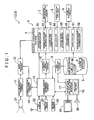
- FIG. 1 is a block diagram showing a schematic configuration of a navigation apparatus 1 including a feature extraction device 4 according to this embodiment.
- the navigation apparatus 1 includes an image recognition device 2 including the feature extraction device 4 and a current position recognition device 3.
- the navigation apparatus 1 extracts a target feature ft (see FIG. 14 ) which is present in a travel direction from a current position using a feature extraction portion 5 based on current position information acquired by a current position information acquisition portion 13, and acquires a map database 6 of feature information F of the target feature ft.
- the feature extraction portion 5 extracts one or more target features ft suitable for use in an image recognition process of a feature with respect to image information, based on the feature information F, from a plurality of features of which the feature information F including at least information of a position and a feature type is stored in the map database 6.
- the navigation apparatus 1 performs image recognition of the target feature ft by an image recognition portion 12 using the acquired feature information F.
- the navigation apparatus 1 corrects the current position information based on a result of the image recognition process of the target feature ft and information of the position of the target feature ft included in the feature information F, and acquires highly-accurate current position information.
- the navigation apparatus 1 performs a navigation process such as a route guidance based on the highly-accurate current position information. Note that an example is described of the navigation apparatus 1 mounted on a vehicle.
- each of the functional portions of the navigation apparatus 1, specifically, the feature extraction portion 5, an image information acquisition portion 11, the image recognition portion 12, the current position information acquisition portion 13, a current position correction portion 14, an estimation error calculation portion 15, a map extraction portion 16, and a navigation calculation portion 17, is a functional portion, which is mounted with one or both of hardware and software (program), for performing various processes with respect to input data with an arithmetic processing device such as a CPU serving as a central member.
- Tables included in the navigation apparatus 1, specifically, a target feature type table 8 and a false recognition table 9, are stored in a storage medium such as a read-only memory (ROM).
- the map database 6 includes a device, including a recording medium in which information is storable and a drive unit thereof, such as a hard disk drive, a DVD drive including a DVD-ROM, and a CD drive including a CD-ROM as a hardware configuration.
- a device including a recording medium in which information is storable and a drive unit thereof, such as a hard disk drive, a DVD drive including a DVD-ROM, and a CD drive including a CD-ROM as a hardware configuration.
- the map database 6 is a database storing a plurality of pieces of map information M divided for each predetermined region and a plurality of pieces of the feature information F associated with the map information.
- FIG. 2 is an illustrative view showing an example of a configuration of the map information M and the feature information F stored in the map database 6.
- the map database 6 stores a road network layer m1, a road shape layer m2, and a feature layer m3.
- the map database 6 corresponds to a feature information storage unit of the present invention.
- the road network layer m1 is a layer showing connection information of roads. Specifically, the road network layer m1 includes information of a large number of nodes n including position information on a map expressed by latitude and longitude and information of a large number of links k which connect two nodes n to form the road. Each link k includes information of a type of road (type such as an expressway, a toll road, a national road, and a prefectural road), and link length as link information thereof.
- the road shape layer m2 is a layer which is stored in association with the road network layer m1 and shows a shape of the road.
- the road shape layer m2 includes information of a large number of road shape complementary points s, arranged between two nodes n (on the link k) and including the position information on the map expressed by the latitude and longitude, and information of a road width.
- the map information M is formed by the information stored in the road network layer m1 and the road shape layer m2.
- the feature layer m3 is a layer which is associated with the road network layer m1 and the road shape layer m2 and stores information of various features provided on the road or in the vicinity of the road, i.e., the feature information F.
- the feature of which the feature information F is stored in the feature layer m3 includes a road marking provided on a surface of the road.
- Examples of the road marking as the feature include, for example, a crosswalk, a stop line, a passing zone marking for each travel direction (a straight arrow, a right turn arrow, and the like) designating the travel direction of each lane, an intersection shape marking (a cross mark, a T mark, and the like), a segment line (a solid line, a dotted line, a double line, and the like) which divides the lanes along the road, a speed indication, and various paint markings such as a zebra zone.
- various features such as a traffic light, a sign, an overpass, and a tunnel other than the road markings may be included as the feature storing the feature information F.
- the feature information F includes information of the position of each feature and information of an attribute as content thereof.
- the information of the position includes information of a position (latitude and longitude) of a representative point of each feature on the map and information of a direction of each feature.
- the representative point of the feature is set at a central position in a length direction and a width direction of each feature, for example.
- the information of the attribute includes information of the feature type, a figuration of the feature, and a state of the feature.
- the information of the feature type is information representing the feature type of each feature.
- the features which basically have the same shape are defined as one feature type.
- the information of the feature type is information representing a specific type of the road marking such as the straight arrow, the right turn arrow, the cross mark, the T mark, the stop line, and the crosswalk.
- the information of the figuration of the feature includes information of a shape, size, and color of each feature.
- the information of the state of the feature includes information of the state of the feature which influences the image recognition process of each feature, such as a state of wear of each actual feature.
- the current position information acquisition portion 13 functions as a current position information acquisition unit which acquires the current position information showing the current position, i.e., a present position of the vehicle.
- the current position information acquisition portion 13 is connected with a GPS receiver 22, a direction sensor 23, and a distance sensor 24.
- the GPS receiver 22 is a device which receives a GPS signal from a global positioning system (GPS) satellite.
- GPS global positioning system
- the GPS signal is normally received every one second and is output to the current position information acquisition portion 13.
- the current position information acquisition portion 13 can analyze the signal from the GPS satellite received by the GPS receiver 22 and acquire information of the present position (latitude and longitude), the travel direction, a moving speed, and the like of the vehicle.
- the direction sensor 23 is a sensor which detects the travel direction of the vehicle or a change of the travel direction thereof.
- the direction sensor 23 is formed of, for example, a gyro-sensor, a geomagnetic sensor, an optical rotation sensor and a rotary variable resistor attached to a rotary portion of a steering wheel, and an angular sensor attached to a wheel portion.
- the direction sensor 23 outputs a detection result thereof to the current position information acquisition portion 13.
- the distance sensor 24 is a sensor which detects a vehicle speed and a moving distance of the vehicle.
- the distance sensor 24 is formed of, for example, a vehicle speed pulse sensor which outputs a pulse signal every time a drive shaft, and a wheel of the vehicle rotates a certain amount, a yaw/G sensor which detects an acceleration of the vehicle, and a circuit which integrates the detected acceleration.
- the distance sensor 24 outputs information of the vehicle speed and the moving distance as the detection result to the current position information acquisition portion 13.
- the current position information acquisition portion 13 performs a calculation of identifying the current position by a known method based on the output from the GPS receiver 22, the direction sensor 23, and the distance sensor 24.
- the current position information acquisition portion 13 acquires the map information M of the vicinity of the current position extracted from the map database 6 by the map extraction portion 16 and performs a known map-matching based thereon to correct the current position to be on the road shown by the map information M.
- the information of the current position acquired in this manner is information including an error due to detection accuracy of each sensor 22 to 24.
- the current position information acquisition portion 13 acquires the current position information including the information of the present position of the vehicle represented by the latitude and longitude and the information of the travel direction of the vehicle by a result of the calculation of identifying the current position described above.
- the current position information is output to the feature extraction portion 5, the current position correction portion 14, the estimation error calculation portion 15, the map extraction portion 16, and the navigation calculation portion 17.
- the map extraction portion 16 extracts the map information M of the vicinity of the current position from the map database 6 based on the current position information and outputs the map information M to the current position information acquisition portion 13 for use in a process of the map-matching by the current position information acquisition portion 13.
- the map extraction portion 16 also extracts the map information M of a region requested by the navigation calculation portion 17 from the map database 6 and outputs the map information M to the navigation calculation portion 17 for use in a navigation process by the navigation calculation portion 17.
- the estimation error calculation portion 15 functions as an estimation error calculation unit which obtains an estimation error as an estimation value of the error of the current position information.
- the estimation error is the estimation value of a maximum error assuming a case with the worst condition of acquisition of the current position information by the current position information acquisition portion 13.
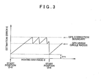
- the estimation error is the error of the travel direction of the vehicle (from the current position), and is obtained by an addition of a distance factor error which increases according to the moving distance of the vehicle and a fixed factor error which is irrelevant to the moving distance of the vehicle.
- the reference symbol D denotes the moving distance of the current position from a predetermined start position and is obtained based on the current position information.
- the start position is a position shown by the current position information after correction when the current position information is corrected by the current position correction portion 14.
- the reference symbol a denotes a distance factor error coefficient representing the maximum value per unit distance of the error integrated in proportion to the moving distance D. Examples of an error factor defining the distance factor error coefficient a include the detection error of the distance sensor 24 and the direction sensor 23.
- the reference symbol b denotes a start error representing the maximum value of the error already included in the current position information at the start position.
- Examples of an error factor defining the start error b include an error due to image recognition accuracy of the image recognition portion 12, an error due to a displacement of an attachment position and an attachment angle of an image-taking device 21, and an error due to an accuracy of the position information included in the feature information F of the target feature ft (see FIG. 14 ).
- the reference symbol c denotes a calculation error representing the maximum value of an error caused due to a calculation process of the estimation error E.
- Examples of an error factor defining the calculation error c include an error due to a rounding of a value at the time of a calculation of a delay due to processing time.
- the reference symbol aD denotes the distance factor error
- the start error b and the calculation error c are the fixed factor error.
- FIG 3 is a view showing an example of a change of the estimation error E when the vehicle travels at an approximately constant speed.
- the feature extraction portion 5 extracts one or more target features ft (see FIG. 14 ) suitable for use in the image recognition process in the image recognition portion 12, based on the feature information F of each feature, from the plurality of the features of which the feature information F is stored in the map database 6.
- the feature extraction portion 5 functions as a main configuration of the feature extraction device 4 according to the present invention. Therefore, in this embodiment, the feature extraction portion 5 includes a grouping interval determination unit 51, a reference feature retrieval unit 52, a feature group formation unit 53, an exclusion unit 54, a feature group re-formation unit 55, a feature set formation unit 56, and an extraction unit 57.
- the feature extraction portion 5 also includes a feature information acquisition unit 58 for acquiring the feature information F of the target feature ft extracted by the extraction unit 57 from the map database 6.
- Each unit forming the feature extraction portion 5 is formed of software (program) for operating the arithmetic processing device such as the CPU. The function and the operation of each unit of the feature extraction portion 5 are described later in detail using a flowchart.
- a recognition rate calculation portion 7 functions as a recognition rate calculation unit which calculates the recognition rate in the image recognition process by the image recognition portion 12 for each of the target features ft extracted by the feature extraction portion 5 and feature sets S (S1 to S7) (see FIG. 14 ).
- the feature sets S (S1 to S7) are formed by the feature set formation unit 56 of the feature extraction portion 5 and are formed of one or more features as described later.
- the function and the operation of the recognition rate calculation portion 7 are also described later in detail using a flowchart in a similar manner to that of each unit of the feature extraction portion 5.
- the target feature type table 8 is a table storing information of the feature type, which is to become an extraction target as the target feature ft (see FIG 14 ) and is suitable for use in the image recognition process, of the feature types of the plurality of the features of which the feature information F is stored in the map database 6.
- the feature types as the extraction target include, for example, the crosswalk, the stop line, the straight and right/left turn arrows, the cross mark, and the T mark.
- the exclusion unit 54 of the feature extraction portion 5 performs a process of excluding the feature of the feature type which is a non-target of extraction, from feature groups G (G1 to G5) (see FIG 12 ) based on the target feature type table 8.
- the feature groups G (G1 to G5) are formed by the feature group formation unit 53 of the feature extraction portion 5 and are formed of one or more features as described later.
- the false recognition table 9 is a table storing information of a combination of the feature types, which have a possibility of being falsely recognized with each other, of the plurality of the feature types as the extraction target. Examples of the combination of the feature types which have the possibility of being falsely recognized with each other include the stop line and the crosswalk, the cross mark and the T mark, and the T mark and the stop line.
- the false recognition table 9 also stores information defining which feature type of the feature is to be excluded by the exclusion unit 54, for the combination of the feature types which may be falsely recognized with each other. Which feature type of the feature to exclude is defined in advance based on the recognition rate in the image recognition process by the image recognition portion 12.
- the feature of the feature type with a lower recognition rate in the image recognition process is excluded.
- the features of both feature types are excluded.
- the stop line is excluded regarding the stop line and the crosswalk, or that the T mark is excluded regarding the stop line and the T mark.
- the image information acquisition portion 11 functions as an image information acquisition unit which acquires the image information in the vicinity of the current position taken by the image-taking device 21.
- the image-taking device 21 is a camera or the like including an image-taking element and is provided in a position which enables image-taking of the surface of the road at least in the vicinity of the vehicle (current position).
- a back camera or the like may be used, for example.
- the image information acquisition portion 11 imports the analog image information taken by the image-taking device 21 at predetermined time intervals, and acquires the image information in digital signals by conversion.
- the time interval of import of the image information may be, for example, approximately 10 to 50 ms. Accordingly, the image information acquisition portion 11 can consecutively acquire the image information of a plurality of frames taken by the image-taking device 21.
- the acquired image information is output to the image recognition portion 12.
- the image recognition portion 12 functions as an image recognition unit which performs the image recognition process with respect to the image information acquired by the image information acquisition portion 11.
- the image recognition portion 12 performs the image recognition process of the target feature ft using the feature information F of the target feature ft (see FIG. 14 ) extracted by the feature extraction portion 5.
- the image recognition portion 12 performs a binarization process, an edge detection process, and the like with respect to the image information acquired by the image information acquisition portion 11, and extracts contour information of the feature (road marking) included in the image information.
- the image recognition portion 12 compares the contour information of the extracted feature and the figuration information included in the feature information F of the target feature ft extracted by the feature extraction portion 5, and determines whether they coincide.
- the image recognition portion 12 When the feature extraction portion 5 extracts the plurality of the features forming one feature set S (S1 to S7) as the target feature ft (see FIG. 14 ), the image recognition portion 12 performs the image recognition process with the plurality of target features ft as a set (one set). That is, for example, when two features f7 and f8 forming the feature set S3 of an example shown in FIG. 14 are extracted as the target feature ft, the image recognition portion 12 determines that the image recognition of the target feature ft has succeeded under the condition that both of the two features f7 and f8 have been recognized as an image, and performs a process of outputting the image recognition result to the current position correction portion 14.
- the current position correction portion 14 functions as a current position correction unit which corrects the current position information based on a result of the image recognition process by the image recognition portion 12 and the position information of the target feature ft (see FIG 14 ) included in the feature information F extracted by the feature extraction portion 5.
- the current position correction portion 14 first calculates a positional relation of the vehicle and the target feature ft at the time of acquisition of the image information including the image of the target feature ft, based on the image recognition result of the image recognition portion 12 and the attachment position, the attachment angle, a viewing angle, and the like of the image-taking device 21.
- the current position correction portion 14 calculates and acquires highly-accurate position information of the vehicle with the position information of the target feature ft (feature information F) serving as a reference, based on a calculation result of the positional relation of the vehicle and the target feature ft and the position information of the target feature ft included in the extracted feature information F extracted by the feature extraction portion 5. Based on the highly-accurate position information of the vehicle acquired in this manner, the current position correction portion 14 corrects the information of the present position of the vehicle included in the current position information acquired by the current position information acquisition portion 13. As a result, the current position information acquisition portion 13 acquires highly-accurate current position information after correction.
- the current position correction portion 14 calculates the positional relation of the target feature ft, which is in a frontmost location in the travel direction of the vehicle (i.e., the target feature ft of which the image recognition process has been performed last), of the plurality of target features ft and the vehicle at the time of the acquisition of the image information including the image of the target feature ft.
- the current position correction portion 14 calculates and acquires the highly-accurate position information of the vehicle based on the calculation result and the feature information F of the target feature ft, and performs the process of correcting the current position information.
- the navigation calculation portion 17 is a calculation process unit which operates with an application program 18 for executing a navigation function such as a current position display, a route calculation from a departure point to a destination, a course guidance to the destination, and a destination retrieval.
- a navigation function such as a current position display, a route calculation from a departure point to a destination, a course guidance to the destination, and a destination retrieval.
- the navigation calculation portion 17 acquires the map information M of the vicinity of the vehicle from the map database 6 using the map extraction portion 16 to display the image of the map on a display device 25, and performs a process of displaying a current position mark based on the current position information to overlap on the image of the map.
- the navigation calculation portion 17 also performs the course guidance using one or both of the display device 25 and a voice output device 26 based on a route from the departure point to the destination calculated by a known method and the current position information.
- the navigation calculation portion 17, the display device 25, and the voice output device 26 function as a guidance information output unit of the navigation apparatus 1.
- the navigation calculation portion 17 is also connected with various known configurations required for a navigation apparatus such as a remote control and a touch panel provided integrally with the display device 25 as a user interface.
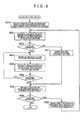
- FIG. 4 is a flowchart showing a processing order of the current position recognition method using the image recognition method according to the present invention.
- the image information acquisition portion 11 first acquires the image information in the vicinity of the current position taken by the image-taking device 21 (step #01).
- the current position information acquisition portion 13 acquires the current position information (step #02).
- the acquired current position information is information including the information of the present position and the information of the travel direction of the vehicle calculated and identified in the current position information acquisition portion 13 based on the output of the GPS receiver 22, the direction sensor 23, and the distance sensor 24.
- the estimation error calculation portion 15 calculates the estimation error E of the current position information (step #03).
- a calculation method of the estimation error E is as described above.
- the feature extraction portion 5 extracts the target feature ft (see FIG 14 ) (step #04) as the target of the image recognition process in the image recognition portion 12, based on the feature information F of each feature f, from the plurality of the features f of which the feature information F is stored in the map database 6.
- An extraction method of the target feature ft by the feature extraction portion 5 will be described later in detail.
- the process returns to step #01.
- the feature extraction portion 5 acquires the feature information F of the target feature ft (step #06) extracted in step #04 from the map database 6 using the feature information acquisition unit 58.
- the image recognition portion 12 performs the image recognition process (step #07) of the target feature ft with respect to the image information acquired in step #01 using feature information F of one or more target features ft (see FIG 14 ) acquired in step #06.
- step #07 the image recognition process
- step #08: No the image recognition of the target feature ft has failed as a result of step #07
- step #08: Yes the current position correction portion 14 performs the process of correcting the current position information (step #09) based on the result of the image recognition process of step #07 and the feature information F of the target feature ft acquired in step #06.
- the current position correction portion 14 calculates and acquires the highly-accurate position information of the vehicle with the position information of the target feature ft (feature information F) as the reference based on the calculation result of the positional relation of the vehicle and the target feature ft, which is based on the image recognition process of step #07, and the position information of the target feature ft, which is included in the feature information F acquired in step #06, and corrects the current position information based thereon.
- the current position information acquisition portion 13 can acquire the highly-accurate current position information after correction.
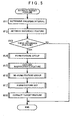
- FIG. 5 is a flowchart showing an overview of a processing order of the feature extraction method according to this embodiment.
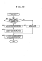
- FIGS. 6 to 10 are flowcharts respectively showing details of a processing order of a feature group formation step (step #14), an exclusion step (step #15), a feature group re-formation step (step #16), a feature set formation step (step #17), and an extraction step (step #18) in the feature extraction method shown in FIG 5 .
- FIGS. 6 to 10 are flowcharts respectively showing details of a processing order of a feature group formation step (step #14), an exclusion step (step #15), a feature group re-formation step (step #16), a feature set formation step (step #17), and an extraction step (step #18) in the feature extraction method shown in FIG 5 .
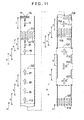
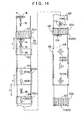
- 11 to 14 are illustrative views for sequentially illustrating each process of the feature extraction method using a specific example of the plurality of the features, of which the feature information F is stored in the map database 6, arranged along the road.
- the feature extraction method according to this embodiment will be described below in detail using the drawings.
- the target feature ft is extracted for a purpose of recognizing the feature, present on a near (rear) side with respect to the stop line as a reference feature fb, as an image and correcting the current position information, in order to precisely perform a brake assist control of the vehicle at the stop line.
- “fore” and “rear” refer to directions along the road regarding an arrangement of the feature, and “fore” represents a direction (far side in the travel direction) identical with the travel direction of the vehicle and “rear” represents an opposite direction (near side in the travel direction) with respect to the travel direction of the vehicle.
- a plurality of features f1 to f18 are generically referred to simply as “feature f”
- the plurality of the feature groups G1 to G5 and the like are generically referred to simply as “feature group G”
- the plurality of the feature sets S1 to S7 are generically referred to simply as “feature set S.”
- a condition within a grouping interval X in the case of retrieving another feature f within the grouping interval X is applied to all other features f of which at least a part is within the grouping interval X.
- the grouping interval determination unit 51 first determines the grouping interval X (see FIGS. 11 and 13 ) (step #11) depending on the estimation error E calculated in step #3 (see FIG 4 ) described above.
- the estimation error E is the estimation value of the maximum error of the current position information acquired by the current position information acquisition portion 13, and corresponds to a radius of the maximum error with a position shown by the current position information as a center.
- the value twice the estimation error E corresponds to a diameter of the maximum error with the position shown by the current position information as the center, and corresponds to a maximum error range of an actual position of the vehicle with respect to the current position information when seen in the travel direction of the vehicle.
- the plurality of the features f adjacent with a relatively narrow interval can be the target feature ft (see FIG 14 ) when the estimation error E is large, whereby the plurality of the target features ft can be recognition targets of one image recognition process.
- a false recognition of one of the plurality of the features f as another adjacent feature f can be reduced.
- each of the plurality of the features f can be the target feature ft of separate image recognition processes, whereby an opportunity of the image recognition process can be increased even with the same number of the features f which are possible target features ft present in the travel direction from the current position. Therefore, even when the image recognition of one target feature ft has failed, a possibility of succeeding in the image recognition of another target feature ft to obtain the image recognition result can be increased.
- the reference feature retrieval unit 52 retrieves a reference feature fb (step #12) from the plurality of the features f of which the feature information F is stored in the map database 6.
- the reference feature retrieval unit 52 performs retrieval of the reference feature fb within a range of a predetermined distance (for example, 300 m) in the travel direction of the vehicle.
- the reference feature retrieval unit 52 retrieves the stop line, of which the feature type is the stop line and which is further present on the near (rear) side of a connection portion of a narrow street with an arterial highway, as the reference feature fb (see FIGS. 11 to 14 ).
- a predetermined distance for example, 300 m
- the feature f1 which is the stop line in a foremost position (upper left area in the drawing) of the road shown in the drawing is retrieved as the reference feature fb.
- the stop line as the feature f1 is the feature f as a control target when the brake assist control of the vehicle is performed.
- the feature group formation step (step #14) by the feature group formation unit 53, the exclusion step (step #15) of excluding an inappropriate feature by the exclusion unit 54, the feature group re-formation step (step #16) by the feature group re-formation unit 55, the feature set formation step (step #17) by the feature set formation unit 56, and the extraction step (step #18) of the target feature ft by the extraction unit 57 are sequentially executed.
- the steps #14 to #18 will be described below in detail.
- the feature group formation unit 53 performs a process of grouping a cluster of features f, in which an interval of the respective features f is less than or equal to the grouping interval X, to form the feature group G, based on the feature information F of the plurality of the features f stored in the map database 6.
- the feature group formation unit 53 first selects a first feature f on a rear side with respect to a non-extraction-target range Y from the reference features fb (step #21) retrieved in step #12.
- the non-extraction-target range Y is a range in which performing a brake assist of the vehicle with respect to the stop line as the feature f1 (see FIG. 11 ) as the reference feature fb is not appropriate, and is a range of up to 50 m rearward from the reference feature fb along the road, for example.
- the feature group formation unit 53 retrieves another feature f within the grouping interval X on the rear side of the feature f selected in step #21 (step #22). As the grouping interval X, the grouping interval X determined in step #11 is used. When another such feature f is retrieved (step #23: Yes), the retrieved feature f is combined with the feature selected in step #21 to be grouped, whereby the feature group G is formed (step #24). Next, the feature group formation unit 53 further retrieves another feature f within the grouping interval X on the rear side of the feature group G (step #25) formed in step #24.
- the feature group formation unit 53 further combines and groups the retrieved feature f with the feature group G formed in step #24, whereby the feature group G is formed (step #24).
- the feature group formation unit 53 repeats the processes of steps #24 to #26 until another feature f is not retrieved within the grouping interval X on the rear side of the feature group G.
- step #26: No formation of one feature group G is terminated and the process proceeds to step #28.
- step #23 when another feature f is not retrieved within the grouping interval X on the rear side of the selected feature f in step #23 (step #23: No), the feature group G is formed by only one selected feature f (step #27) and the process proceeds to step #28. Accordingly, the feature group G can be individually formed with each feature f which has not been grouped.
- the feature group formation unit 53 further retrieves the feature f on the rear side of the formed feature group G (step #28).
- the feature f on the rear side of the formed feature group G is retrieved (step #29: Yes)
- the first feature f on the rear side of the formed feature group G is selected (step #30) and the process returns to step #22. Accordingly, the formation of the feature group G with the feature f selected in step #30 as the first feature f is further performed.
- step #29: No the process of the feature group formation step (step #14) is terminated.
- Such cases where another feature f is not retrieved on the rear side of the formed feature group G include a case where the vehicle is present between the feature group G and another feature f on the rear side of the feature group G, and a case where the feature information F of the feature f on the rear side of the feature group G is not stored in the map database 6.
- step #21 since characters "STOP" as the feature f2 are present within the non-extraction-target range Y from the stop line as the feature f1 which is the reference feature fb, the crosswalk as the feature f3 is first selected as the first feature f on the rear side of the non-extraction-target range Y (step #21).
- step #22 the stop line as the feature f4 and the characters "STOP" as the feature f5 are retrieved as the features f present within the grouping interval X on the rear side of the feature f3 first selected (step #22, step #23: Yes) and are grouped (step #24).
- the straight arrow as the feature f6 is retrieved as the feature f present within the grouping interval X on the rear side of the feature f5 (step #25, step #26: Yes) which is the rearmost feature of those grouped, and is grouped (step #24). Then, since the feature f is not present within the grouping interval X on the rear side of the feature f6 which is the rearmost feature of those grouped (step #26: No), one feature group G1 is formed by the features f3 to f6.
- the straight arrow as the feature f7 is first retrieved (step #29: Yes).
- the retrieved feature f7 is selected as the first feature f on the rear side of the feature group G1 (step #30), and the cluster of the features f7 to f10 in which the interval of the respective features f is less than or equal to the grouping interval X is grouped to form the feature group G2.
- the feature group G3 is formed by the features f11 to f14
- the feature group G4 is formed by the features f15 to f17.
- the crosswalk as the feature f18 arranged on the rear side of the feature group G4 beyond the grouping interval X is selected as the first feature on the rear side of the feature group G4 (step #30).
- the feature group G5 is formed by only one selected feature f18 (step #27).
- the process of the feature group formation step (step #14) is thus terminated.
- the exclusion unit 54 performs a process of excluding the feature f (inappropriate feature) inappropriate for use in the image recognition process of the feature f with respect to the image information from the cluster of the features within the feature groups G (G1 to G5) formed in the feature group formation step (step #14).
- the feature f of at least one of the feature types is excluded as the feature f inappropriate for use in the image recognition process in the exclusion step (step #15).
- the exclusion unit 54 retrieves the feature f having a feature attribute as the non-target of extraction within the feature group G (step #31) based on information of the feature attribute included in the feature information F of each feature f in the feature group G.
- the retrieved feature f is excluded from the feature group G (step #33).
- the feature attribute as the non-target of extraction include the feature attribute inappropriate for the image recognition process such as the feature type which is not suitable for use in the image recognition process due to a complicated shape as in the characters of "STOP" and the like and a state of the feature which is not suitable for use in the image recognition process due to considerable wear.
- whether the feature type is the non-target of extraction not suitable for use in the image recognition process is determined based on the target feature type table 8. That is, as described above, the target feature type table 8 stores the information of the feature type, which is to become the extraction target as the target feature ft, suitable for use in the image recognition process. Thus, the exclusion unit 54 determines that the feature f of the feature type not stored in the target feature type table 8 is the feature type (feature attribute) as the non-target of extraction. Note that, in this embodiment, steps #31 to #33 correspond to a non-target feature exclusion step of the present invention.
- the exclusion unit 54 retrieves the plurality of the features f which differ in the feature type within the feature group G and which have the possibility of being falsely recognized with each other (step #34).
- the feature f of at least one of the feature types of the retrieved feature f is excluded from the feature group G (step #36).
- step #36 the process of excluding the feature f of the feature type with at least a lower recognition rate in the image recognition process of the features f of the plurality of the feature types from the feature group G is performed.
- the false recognition table 9 is used for the processes of steps #34 to #36.
- the false recognition table 9 stores the information of the combination of the feature types, which have the possibility of being falsely recognized with each other, of the plurality of the feature types as the extraction target and the information defining which feature type of the feature f is to be excluded in the combination of the feature types which have the possibility of being falsely recognized with each other.
- the exclusion unit 54 determines the combination of the features f of the feature types, of which the information is stored in the false recognition table 9, as the plurality of the features f which have the possibility of being falsely recognized with each other.
- the exclusion unit 54 determines which feature type of the feature f to exclude in the determined combination of the features f of the feature types, which have the possibility of being falsely recognized with each other, based on the information stored in the false recognition table 9.
- which feature type of the feature to exclude it is defined that the feature f of the feature type with the lower recognition rate, based on the recognition rate in the image recognition process, is excluded, as described above. Note that, for the feature types with the same degree of the recognition rate, there may be cases where it is defined that the features f of both feature types are excluded. Note that, in this embodiment, steps #34 to #36 correspond to a false recognition feature exclusion step of the present invention.
- the characters "STOP" as the feature f5 are retrieved as the feature f having the feature attribute as the non-target of extraction within the feature group G1 (step #31, step #32: Yes), and is excluded from the feature group G1 (step #33).
- the feature f5 corresponds to the feature f of the feature type not suitable for use in the image recognition process based on the target feature type table 8.
- the combination of the crosswalk as the feature f3 and the stop line as the feature f4 is retrieved as the plurality of the features f which differ in the feature type within the feature group G1 and which have the possibility of being falsely recognized with each other (step #34, step #35: Yes).
- the stop line as the feature f4 with the lower recognition rate in the image recognition process is excluded from the feature group G1 (step #36) based on the false recognition table 9.
- the straight arrow as the feature f9 is retrieved as the feature f having the feature attribute as the non-target of extraction within the feature group G2 (step #31, step #32: Yes), and is excluded from the feature group G2 (step #33).
- the feature f9 corresponds to the feature f in the state where the information of the state of the feature included in the feature information F is not suitable for use in the image recognition process due to considerable wear. Note that, since the four features f7 to f10 within the feature group G2 are all of the same feature type, the plurality of the features f, which differ in the feature type within the feature group G2 and may be falsely recognized with each other, are not retrieved (step #34, step #35: No).
- the features f11, f12 and f14 are excluded in the feature group G3, and all of the features f15 to f17 within the feature group G4 are excluded in the feature group G4.
- the features f within the feature group G4 are the cross marks as the feature f15 and f17 and the T mark as the feature f16, and since it is defined in the false recognition table 9 that both are to be excluded regarding these feature types, all of the features f15 to f17 are excluded in the feature group G4. Since only the crosswalk as the feature f18 is present within the feature group G5 and the feature f18 does not correspond to the feature having the feature attribute as the non-target of extraction (step #32: No), no feature f is excluded in the feature group G5. The exclusion step (step #15) is thus terminated.
- the feature group re-formation unit 55 performs the process of grouping the cluster of features f, in which the interval of the respective features f is less than or equal to the grouping interval X, of one or more features f within the feature group G remaining as a result of the exclusion step (step #15) to newly form the feature group G.
- the process of forming the new feature group G by the feature group re-formation step (step #16) is performed within one old feature group G among the feature groups G (G1 to G5) formed in the feature group formation step (step #14).
- the feature group G newly formed by the feature group re-formation step (step #16) is hereinafter called a "new feature group G”
- the feature group G formed in the feature group formation step (step #14) is called an "old feature group G.”
- the feature group re-formation unit 55 selects the foremost feature f excluding the feature f excluded in the exclusion step (step #15) within the old feature group G (step #41), for one of the old feature groups G (G1 to G5) formed in the feature group formation step (step #14).
- the feature group re-formation unit 55 retrieves another feature f within the grouping interval X on the rear side of the feature f selected in step #41 (step #42).
- the grouping interval X the grouping interval X determined in step #11 is used in a similar manner to that of the feature group formation step (step #14).
- the retrieved feature f is combined with the feature selected in step #41 to be grouped, whereby the new feature group G is formed (step #44).
- the feature group re-formation unit 55 further retrieves another feature f within the grouping interval X on the rear side of the new feature group G formed in step #44 (step #45).
- the feature group re-formation unit 55 further combines and groups the retrieved feature f with the new feature group G formed in step #44, whereby the new feature group G is formed (step #44).
- the feature group re-formation unit 55 repeats the processes of steps #44 to #46 until another feature f is not retrieved within the grouping interval X on the rear side of the new feature group G.
- step #46 When another feature f is not retrieved (step #46: No) within the grouping interval X on the rear side of the new feature group G, formation of one new feature group G is terminated and the process proceeds to step #48. Also, when another feature f is not retrieved (step #43: No) within the grouping interval X on the rear side of the selected feature f in step #43, the new feature group G is formed by only one selected feature f (step #47), and the process proceeds to step #48. Accordingly, the new feature group G can be formed individually for each feature f which has not been grouped.
- the feature group re-formation unit 55 determines whether the new feature group G is formed for all of the features f excluding the feature f excluded in the exclusion step (step #15) within the old feature group G which is presently a process target.
- the feature group re-formation unit 55 selects the first feature f on the rear side of the new feature group G already formed (step #49) and the process returns to step #42. Accordingly, the formation of the new feature group G with the feature f selected in step #49 as the first feature f is further performed.
- step #16 the process of the feature group re-formation step (step #16) is terminated.
- step #17 the extraction step (step #18), the new feature group G is treated as the feature group G when the new feature group G is formed within the old feature group G.
- the old feature group G in which the new feature group G is not formed is treated as the feature group G, as in the case where all of the features f within the old feature group G are excluded.
- the crosswalk as the feature f3 of the old feature group G1 is first selected as the foremost feature f (step #41) excluding the feature f excluded in the exclusion step (step #15) in the old feature group G1.
- the straight arrow as the feature f6 is retrieved as the feature f present within the grouping interval X on the rear side of the selected feature f3 (step #42, step #43: Yes), and is grouped (step #44).
- the new feature group is thus formed for all of the features f within the old feature group G1 (step #48: Yes) excluding the feature f excluded in the exclusion step (step #15), whereby one new feature group G1n is formed by the features f3 and f6 and the process of the feature group re-formation step (step #16) for the old feature group G1 is terminated.
- the straight arrow as the feature f7 is first selected as the foremost feature f (step #41) excluding the feature f excluded in the exclusion step (step #15) within the old feature group G2.
- the straight arrow as the feature f8 is similarly retrieved as the feature f present within the grouping interval X on the rear side of the selected feature f7 (steps #42 and #43: Yes), and is grouped (step #44).
- step #45, step #46: No which is the rearmost feature of those grouped
- one new feature group G2n is formed by the features f7 and f8.
- the straight arrow as the feature f10 is selected as the feature f adjacent to and on the rear side of the new feature group G2n (step #49) excluding the feature f excluded in the exclusion step (step #15). Since another feature f is not present on the rear side of the feature f10 in the old feature group G2 (step #42, step #43: No), a new feature group G2m is formed by only one selected feature f10 (step #47).
- the new feature group is thus formed for all of the features f within the old feature group G2 (step #48: Yes) excluding the feature f excluded in the exclusion step (step #15), whereby the process of the feature group re-formation step (step #16) for the old feature group G2 is terminated.
- a new feature group G3n is formed by only one feature f13 and a new feature group G5n is formed by only one feature f18. Note that, for the old feature group G4, since all of the features f within the old feature group G4 are excluded in the exclusion step (step #15), the new feature group is not formed, whereby the old feature group G4 is treated as the feature group G in the subsequent feature set formation step (step #17) and the extraction step (step #18).
- the feature set formation unit 56 performs a process of forming the cluster of the features f, in which the interval of the respective features f is less than or equal to the grouping interval X, of the same feature type into a set as the feature set S, for one or more of the features f within the feature group G. As shown in FIG.
- the feature set formation unit 56 determines whether all of the features f within the feature group G is excluded (step #51) by the exclusion step (step #15) for one of the feature groups G (G1n, G2n, G2m, G3n, G4, and G5n) formed at this point.
- the feature set formation unit 56 forms all of the features f within the feature group G into the set as the feature set S (step #52).
- the feature set formation unit 56 selects the foremost feature f within the feature group G (step #53). Then, one or more of the other features f, in which the interval of the respective features f is less than or equal to the grouping interval X, of the same feature type as that of the feature f selected in step #53 are retrieved (step #54). As the grouping interval X, the grouping interval X determined in step #11 is used in a similar manner to that of the feature group formation step (step #14). Whether the feature types are the same is determined based on the feature information F of each feature f. When another such feature f is retrieved (step #55: Yes), the feature set formation unit 56 combines the retrieved one or more features f with the feature selected in step #53 to form the set as the feature set S (step #56).
- step #55: No when another feature f of the same feature type is not retrieved within the grouping interval X on the rear side of the feature f selected in step #53 (step #55: No), the feature set formation unit 56 does not perform the process of step #56. Then, the feature set formation unit 56 determines whether all of the features f within the feature group G are selected (step #57). When all of the features f within the feature group G is not selected (step #57: No), the feature f adjacent to and on the rear side of the feature f previously selected in step #53 is selected (step #58) excluding the feature f excluded in the exclusion step (step #15).
- step #54 The process returns to step #54, and one or more of the other features f, in which the interval of the respective features f is less than or equal to the grouping interval X, of the same feature type as that of the feature f selected in step #58 are retrieved (step #54).
- step #55: Yes the feature set S is formed (step #56) in a similar manner as described above.
- step #57 When all of the features f within the feature group G are selected (step #57: Yes), the feature set S is formed individually for each feature f for all of the features f which have not been formed into the set (step #59) excluding the feature f excluded in the exclusion step (step #15) within the feature group G which is presently the process target The feature set formation step (step #17) is thus terminated.
- step #51 No
- step #15 the exclusion step
- step #15 the crosswalk as the feature f3 is then selected as the foremost feature f within the feature group G1n (step #53).
- step #54, step #55: No the straight arrow as the feature f6 adjacent to and on the rear side of the previously selected feature f is selected (step #58).
- the straight arrow as the feature f of the same feature type as that of the feature f6 is not present within the feature group G1n. Since all of the features f within the feature group G1n are thus selected (step #57: Yes), the feature sets S1 and S2 are respectively formed by each of the features f3 and f6 which have not been formed into the set (step #59), whereby the process of the feature set formation step (step #17) for the feature group G1n is terminated.
- the straight arrow as the feature f7 is then selected as the foremost feature f within the feature group G2n (step #53). Then, the straight arrow as the feature f8 is retrieved as the feature f, in which the interval of the respective features f is less than or equal to the grouping interval X, of the same feature type as that of the selected feature f (step #54, step #55: Yes). Thus, the retrieved feature f8 is combined with the selected feature f7 to form the set as the feature set S3.
- step #57: Yes all of the features f within the feature group G1n are selected (step #57: Yes) and the feature f which has not been formed into the set is not present, whereby the process of the feature set formation step (step #17) for the feature group G2n is thus terminated.
- step #51: Yes all of the features f within the feature group G4 is excluded (step #51: Yes) by the exclusion step (step #15).
- step #15 all of the features f15 to f17 within the feature group G4 is formed into the set as the feature set S6 (step #52).
- the process of the feature set formation step (step #17) for the feature group G4 is thus terminated.
- the feature sets S4, S5, and S7 are respectively formed individually by each feature f10, f13, and f18 (step #59).
- the extraction unit 57 performs a process of selecting one feature set S within the feature group G and extracting one or more features f forming the selected feature set S as the target feature ft suitable for use in the image recognition process by the image recognition portion 12. As shown in FIG.
- the extraction unit 57 determines whether the plurality of the feature sets S are present within the feature group G (step #61) for one of the feature groups G (G1n, G2n, G2m, G3n, G4, and G5n) formed at this point When the plurality of the feature sets S are not present within the feature group G (step #61: No), the extraction unit 57 selects one feature set S present within the feature group G (step #62) and the process proceeds to step #65.
- the extraction unit 57 calculates the recognition rate in the image recognition process of each feature set S within the feature group G (step #63).
- the recognition rate of each feature set S is calculated by the recognition rate calculation portion 7.
- the recognition rate calculation portion 7 calculates the recognition rate by using a recognition coefficient set in advance depending on the feature type to multiply the recognition coefficients depending on the feature type of each feature f forming the feature set S.
- a recognition rate R is obtained by the following formula (2).
- the recognition coefficients C1, C2, ...Cn are all set as a value between 0 and 1.
- the recognition rate R of each feature set S becomes a smaller value as the number of the features included in the feature set S becomes larger.
- the extraction unit 57 selects the feature set S with the highest recognition rate in the plurality of the feature sets S within one feature group G (step #64), and the process proceeds to step #65. Then, the extraction unit 57 extracts one or more features f forming the feature set S selected in steps #62 or #64 as the target feature ft (step #65).
- the recognition rates of the feature sets S1 and S2 are respectively calculated (step #63).
- the recognition rate R of the feature set S1 is equal to the recognition coefficient (for example, 0.9) of the crosswalk.
- the recognition rate R of the feature set S2 is equal to the recognition coefficient (for example, 0.8) of the straight arrow.
- the recognition rate of the feature set S1 is high, the feature set S1 is selected (step #64), and the feature f3 forming the selected feature set S1 is extracted as the target feature ft (step #65).
- step #61 No. Therefore, each of the feature sets S3, S4, S5, S6, and S7 is selected, and the features f forming each feature set S3, S4, S5, S6, and S7 are extracted as the target feature ft, respectively.
- the feature set S6 is formed by excluding all of the features f within the feature group G4 by the exclusion step (step #15) and forming all of the features f15 to f17 into the set as the feature set S6.
- the feature set S6 is selected (step #62), whereby all of the features f15 to f17 forming the feature set S6 are extracted as the target feature ft.
- the image recognition portion 12 performs the image recognition process with the plurality of target features ft as the set (one set) in this embodiment. Accordingly, the cluster of features f, in which the interval of the respective features f is less than or equal to the grouping interval X, of the same feature type can be combined as the feature set S as the target feature ft.
- the target feature ft when used in the image recognition process, it is possible to perform the image recognition process with the cluster of the features f as the set even if the cluster of the features f of the same feature type are arranged with the relatively narrow interval, whereby enabling to reduce the false recognition of one of the features f in the cluster with another adjacent feature f and to increase the recognition rate of the target feature ft.
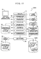
- FIG. 15 is a block diagram showing a schematic configuration of a feature database creation device 30 including the feature extraction device 4 according to this embodiment.
- the feature database creation device 30 creates the map database 6, which also serves as a feature database 40, based on the feature information F stored in a feature information storage portion 32 and the map information M stored in a map information storage portion 33. That is, the feature database creation device 30 extracts one or more target features ft suitable for use in the image recognition process of the feature with respect to the image information, based on the feature information F, from the plurality of the features of which the feature information F including at least the information of the position and the feature type is stored in the feature information storage portion 32. The feature database creation device 30 then acquires the feature information F of the extracted target feature ft from the feature information storage portion 32, associates the feature information F with the map information M acquired from the map information storage portion 33, and stores the feature information F in the map database 6.
- the feature database creation device 30 can create the map database 6, which also serves as the feature database 40, storing the feature information F of the target feature ft extracted in advance to be suitably used for the image recognition process of the feature with respect to the image information.
- the created map database 6 can be suitably used for, for example, an image recognition device which performs the image recognition of the target feature ft, a current position recognition device which corrects the current position information based on the result of the image recognition process of the target feature ft by the image recognition device and the information of the position of the target feature ft included in the feature information F to acquire the highly-accurate current position information.
- the process of extracting one or more target features ft suitable for use in the image recognition process of the feature with respect to the image information from the plurality of the features of which the feature information F is stored in the map database 6 is unnecessary. Therefore, the image recognition device or the current position recognition device in which the process is simplified compared with the image recognition device 2 or the current position recognition device 3 according to the first embodiment described above can be realized.
- the configurations of the feature extraction portion 5, the recognition rate calculation portion 7, the target feature type table 8, and the false recognition table 9 that form the feature extraction device 4 in the feature database creation device 30 are basically the same as those of the first embodiment described above.
- the grouping interval X is a fixed value, and therefore, the feature extraction portion 5 differs from that of the first embodiment described above in that the grouping interval determination unit 51 is not provided.
- the feature database creation device 30 and a feature database creation method according to this embodiment will be described below in detail focusing on a difference from the first embodiment described above.
- the feature information storage portion 32 is a storage unit storing the feature information F about a large number of the features which are actually present.
- the feature information F is created based on an actual situation shown in an aerial photograph, a drawing, a video image taken by a measurement vehicle or in a field investigation, and the like.
- the feature information storage portion 32 stores the feature information F created based on the actual situations regardless of suitability for the image recognition process of the feature with respect to the image information.
- the feature information F of each feature stored in the feature information storage portion 32 includes the information of the position and the information of the attribute of each feature as the content in a similar manner to that of the first embodiment described above.
- the information of the position includes the information of the position (latitude and longitude) of the representative point of each feature on the map and of the direction of each feature.
- the information of the attribute includes the information of the feature type, the figuration of the feature, and the state of the feature.
- the information of the feature type is information representing the feature type of each feature.
- the information of the figuration of the feature includes the information of the shape, size, color, and the like of each feature.
- the information of the state of the feature includes the information of the state of the feature which influences the image recognition process of each feature, such as the state of wear of each actual feature.
- the feature information storage portion 32 corresponds to the feature information storage unit of the present invention.
- the map information storage portion 33 is a storage unit storing the plurality of pieces of the map information M divided for each predetermined region.
- the content of the map information M is similar to the content of the information stored in the road network layer m1 and the road shape layer m2 stored in the map database 6 in the first embodiment described above.
- An input device 31 includes a computer body, an operation portion such as a keyboard and a mouse, and a display portion such as a monitor.
- the input device 31 includes various software (program) forming a user interface so that a creation instruction can be input when creating data, in which the feature information F and the map information M are associated, to be stored in the map database 6.
- Examples of the creation instruction input from the input device 31 include an instruction of a creation area of the data to be stored in the map database 6 and an instruction of various settings for creation processing.
- the map extraction portion 16 extracts and acquires the map information M, corresponding to an area instructed by the creation instruction input by the input device 31, from the map database 6 and outputs the map information M to the map database creation portion 34, in order for the map database creation portion 34 to create the data to be stored in the map database 6.
- the map database creation portion 34 creates the data in which the feature information F of the target feature ft extracted and acquired by the feature extraction portion 5 and the map information M acquired by the map extraction portion 16 are associated, and stores the data in the map database 6.
- the map database creation portion 34 functions as a storage processing unit which stores the feature information F acquired by the feature information acquisition unit 58 in a predetermined storage unit.
- the map database 6 corresponds to the predetermined storage unit of the present invention that stores the feature information F.
- FIG. 16 is a flowchart showing the processing order of the feature database creation method according to this embodiment.
- the feature extraction portion 5 extracts one or more target features ft (see FIG. 14 ) (step #72) suitable for use in the image recognition process of the feature with respect to the image information, based on the feature information F of each feature, from the plurality of the features of which the feature information F is stored in the feature information storage portion 32, depending on instruction content of the creation area included in the creation instruction.
- the process of the extraction method of the target feature ft by the feature extraction portion 5 is basically similar to the process of the feature extraction method shown in the flowchart of FIG. 5 according to the first embodiment described above.
- the reference feature retrieval unit 52 retrieves the stop line, of which the feature type is the stop line and which is further present on the near (rear) side with respect to the connection portion of the narrow street with the arterial highway, as the reference feature fb (see FIGS. 11 to 14 ) within the creation area included in the creation instruction input in step #71.
- the extraction of the target feature ft (step #72) for each of the plurality of the reference features fb is repeatedly performed.
- the process of the step #11 for determining the grouping interval X is not performed. That is, in this embodiment, the grouping interval X is the fixed value.
- the grouping interval X is preferably set in accordance with an approximate average value of the estimation error which is the estimation value of the error of the current position information separately obtained in the image recognition device or the current position recognition device utilizing the map database 6 created by the feature database creation device 30 according to this embodiment, and may be set as approximately 30 (m), for example.
- the details of the processes of the feature group formation step (step #14) by the feature group formation unit 53, the exclusion step (step #15) excluding the inappropriate feature by the exclusion unit 54, the feature group re-formation step (step #16) by the feature group re-formation unit 55, the feature set formation step (step #17) by the feature set formation unit 56, and the extraction step (step #18) of the target feature ft by the extraction unit 57 in the feature extraction method are similar to the processes of FIGS. 6 to 10 according to the first embodiment described above.
- the feature extraction portion 5 acquires the feature information F of the target feature ft (step #73) extracted in step #72 from the feature information storage portion 32 using the feature information acquisition unit 58.
- the map extraction portion 16 acquires the map information M of the corresponding region (step #74) depending on the instruction content of the creation area included in the creation instruction input by the input device 31.
- the map database creation portion 34 associates the feature information F of the target feature ft acquired in step #73 and the map information M acquired in step #74 (step #75), and stores the feature information F associated with the map information M in the map database 6 which also serves as the feature database 40 (step #76). The process of the feature database creation method is thus terminated.
- FIG. 17 is a block diagram showing a schematic configuration of the feature database creation device 30 including the feature extraction device 4 according to this embodiment.
- the feature database creation device 30 creates the map database 6, which also serves as the feature database 40, based on the feature information F stored in the feature information storage portion 32 and the map information M stored in the map information storage portion 33.
- the feature database creation device 30 extracts one or more target features ft suitable for use in the image recognition process of the feature with respect to the image information, based on the feature information F, from the plurality of the features of which the feature information F including at least the information of the position and the feature type is stored in the feature information storage portion 32, and stores the feature information F acquired based on the extraction result in the map database 6 which also serves as the feature database 40, in a similar manner to that of the second embodiment described above.
- the feature database creation device 30 determines an acquisition range of the feature information F based on a recognition rate integrated value which is an integrated value of the recognition rate in the image recognition process for one or more target features ft (see FIG 14 ) sequentially retrieved along the road from the predetermined reference feature fb, acquires the feature information F of the feature included in the acquisition range from the feature information storage portion 32, and stores the feature information F in the map database 6.
- a recognition rate integrated value which is an integrated value of the recognition rate in the image recognition process for one or more target features ft (see FIG 14 ) sequentially retrieved along the road from the predetermined reference feature fb
- the feature database creation device 30 includes an acquisition range determination portion 35 for determining the acquisition range of the feature information F based on the extraction result of the target feature ft extracted by the feature extraction portion 5, in order to realize such configuration.
- the feature database creation device 30 determines the acquisition range in the direction along the road from the reference feature fb (see FIG. 14 ) for acquiring and storing the feature information F, based on the recognition rate integrated value of the target feature ft sequentially arranged along the road from the reference feature fb.
- a range of the feature information F to be stored can be made appropriate to reduce a data amount of the feature information F stored in the map database 6, while ensuring that the recognition rate in the image recognition process is greater than or equal to a certain rate, even when the map database 6 is used in the image recognition device which performs the image recognition of the target feature ft, the current position recognition device which corrects the current position information based on the result of the image recognition process of the target feature ft by the image recognition device and the information of the position of the target feature ft included in the feature information F to acquire the highly-accurate current position information.
- the map database 6 according to this embodiment can be suitably used as the map database 6 of the navigation apparatus 1 including the image recognition device 2 and the current position recognition device 3 according to the first embodiment described above.
- the feature database creation device 30 according to this embodiment are similar to those of the second embodiment described above.
- the feature database creation device 30 and a feature database creation method according to this embodiment will be described below in detail focusing on a difference from the second embodiment described above.
- the acquisition range determination portion 35 includes a target feature retrieval unit 36 and an acquisition range determination unit 37.
- the target feature retrieval unit 36 functions as a retrieval unit which sequentially retrieves the target features ft (see FIG. 14 ) extracted by the feature extraction portion 5 along the road from the reference feature fb retrieved by the reference feature retrieval unit 52.
- a retrieval method of the reference feature fb is similar to that of the first embodiment described above, a retrieval range in this embodiment is within the range of the creation area included in the creation instruction input by the input device 31.
- the acquisition range determination unit 37 functions as a unit which determines the range of acquisition of the feature information F by the feature information acquisition unit 58 based on the recognition rate integrated value which is the integrated value of the recognition rate in the image recognition process for one or more target features ft retrieved by the target feature retrieval unit 36 from the reference feature fb.
- the acquisition range determination unit 37 performs a process of determining a range from the reference feature fb up to a target feature set of which the recognition rate integrated value is greater than or equal to a predetermined threshold value as the acquisition range of the feature information F.
- the target feature set is the feature set S including the target feature ft, and in the example shown in FIG.
- the feature sets S1, S3, S4, S5, S6, and S7 are the target feature sets.
- the recognition rate integrated value is calculated by the recognition rate calculation portion 7.
- Each unit forming the acquisition range determination portion 35 is formed of the software (program) for operating the arithmetic processing device such as the CPU. The function and the operation of each unit of the acquisition range determination portion 35 will be described later in detail using a flowchart shown in FIG 18 .
- the feature information acquisition unit 58 of the feature extraction portion 5 acquires the feature information F within the acquisition range determined by the acquisition range determination portion 35 from the feature information storage portion 32.
- the map extraction portion 16 extracts and acquires the map information M corresponding to the region instructed by the creation instruction input by the input device 31 from the map database 6.
- the map database creation portion 34 creates the data in which the feature information F extracted and acquired by the feature extraction portion 5 and the map information M acquired by the map extraction portion 16 are associated, and stores the data in the map database 6.
- the map database creation portion 34 functions as the storage processing unit which stores the feature information F acquired by the feature information acquisition unit 58 in the predetermined storage unit, and the map database 6 corresponds to the predetermined storage unit of the present invention that stores the feature information F.
- FIG. 18 is a flowchart showing the processing order of the feature database creation method according to this embodiment. Note that FIG. 14 is to be referenced in the description below as necessary.
- the feature extraction portion 5 extracts one or more target features ft (see FIG. 14 ) (step #82) suitable for use in the image recognition process of the feature with respect to the image information, based on the feature information F of each feature, from the plurality of the features of which the feature information F is stored in the feature information storage portion 32, depending on the instruction content of the creation area included in the creation instruction.
- the extraction method of the target feature ft by the feature extraction portion 5 is similar to that of the second embodiment described above.
- the target feature retrieval unit 36 of the acquisition range determination portion 35 retrieves the target feature set closest to the reference feature fb (step #83).
- the target feature set is the feature set S including the target feature ft.
- the feature set S1 including the feature f3 as the target feature ft is retrieved as the target set closest to the reference feature fb.
- the recognition rate calculation portion 7 calculates the recognition rate integrated value from the reference feature fb (step #84).
- the recognition rate integrated value is the integrated value of the recognition rate of one or more feature sets S extracted along the road from the reference feature fb.
- a recognition rate integrated value Q of the recognition rate of n feature sets S, of which the recognition rates are R1, R2, ...Rn (n is a natural number) from the reference feature fb is obtained by the following formula (3).
- Q 1 - 1 - R ⁇ 1 ⁇ 1 - R ⁇ 2 ⁇ ... ⁇ 1 - Rn
- the recognition rate R of the feature set S is obtained by the formula (2) described above. As described above, since the recognition coefficients C1, C2, ... Cn of each feature f are all set as a value between 0 and 1, the recognition rates R1, R2, ...Rn of each feature set S are also values between 0 and 1, respectively. Thus, the recognition rate integrated value Q becomes a greater value (value closer to 1) as the number of the feature sets S becomes larger. In a state right after the target feature set closest to the reference feature fb is retrieved in step #83, only one feature set S is retrieved, whereby the recognition rate integrated value Q coincides with the recognition rate of the feature set S. In the example shown in FIG.
- the acquisition range determination unit 37 of the acquisition range determination portion 35 determines whether the recognition rate integrated value Q is greater than or equal to the predetermined threshold value (step #85).
- the recognition rate integrated value Q corresponds to a probability of the image recognition of the target feature ft succeeding before the vehicle reaches the reference feature fb, when the map database 6 according to this embodiment is used for the image recognition device 2 or the like according to the first embodiment described above.
- the threshold value is preferably set as a value between 0.90 and 0.99, for example.
- step #85: No When the recognition rate integrated value Q is smaller than the predetermined threshold value (step #85: No), the next target feature set is retrieved (step #86), and the process returns to step #84.
- the target feature set is sequentially retrieved (step #86) in a direction departing from the reference feature fb until the recognition rate integrated value Q is greater than or equal to the predetermined threshold value (step #85: Yes), and the recognition rate integrated value Q is calculated (step #84).
- step #85: Yes When the recognition rate integrated value Q is greater than or equal to the predetermined threshold value (step #85: Yes), the process proceeds to the next step #87.
- the feature set S3 is retrieved as the target feature set following the feature set S1, and the recognition rate integrated values Q of the feature sets S1 and S3 are calculated by the recognition rate calculation portion 7.
- the threshold value is set to 0.98, the recognition rate integrated value Q is smaller than the threshold value.
- the feature set S4 is further retrieved as the following target feature set, and the recognition rate integrated value Q is calculated.
- the process proceeds to the next step #87.
- the acquisition range determination unit 37 of the acquisition range determination portion 35 determines the acquisition range of the feature information F (step #87). That is, the acquisition range determination unit 37 determines the range from the reference feature fb up to the target feature set of which the recognition rate integrated value Q is greater than or equal to the predetermined threshold value as the acquisition range of the feature information F. Specifically, as the feature f within the acquisition range, all of the features f which are present between the reference feature fb and the rearmost feature of the target feature set, of which the recognition rate integrated value Q is greater than or equal to the predetermined threshold value, are included. In this example, the feature f excluded in the exclusion step (step #15) by the exclusion unit 54 is also included.
- the feature extraction portion 5 acquires the feature information F of the feature f included in the acquisition range (step #88) determined in step #87 from the feature information storage portion 32 using the feature information acquisition unit 58.
- the map extraction portion 16 acquires the map information M of the corresponding area (step #89) according to the instruction content of the creation area included in the creation instruction input by the input device 31.
- the map database creation portion 34 associates the feature information F of the target feature ft acquired in step #88 and the map information M acquired in step #89 (step #90), and stores the feature information F associated with the map information M in the map database 6 which also serves as the feature database 40 (step #91).
- the present invention can be used for an image recognition method, a current position recognition method, and the like using feature information. Further, the present invention can suitably be utilized for an image recognition device, a current position recognition device, a navigation apparatus, a vehicle control device, and the like utilizing the methods.
Landscapes
- Engineering & Computer Science (AREA)
- Physics & Mathematics (AREA)
- General Physics & Mathematics (AREA)
- Multimedia (AREA)
- Theoretical Computer Science (AREA)
- Image Analysis (AREA)
- Navigation (AREA)
- Information Retrieval, Db Structures And Fs Structures Therefor (AREA)
- Image Processing (AREA)
- Closed-Circuit Television Systems (AREA)
- Traffic Control Systems (AREA)
Claims (21)
- Merkmalsextraktionsverfahren für eine Merkmalsextraktionsvorrichtung (4), wobei das Verfahren aufweist:einen Schritt des Bildens einer Merkmalsgruppe (Schritt #14) durch Gruppieren einer Ansammlung von Merkmalen, wobei jedes Merkmal eine Fahrbahnmarkierung betrifft und in einer vorbestimmten Merkmalsinformationsspeichereinheit (32) gespeichert ist und eine Information der Position der Fahrbahnmarkierung entlang einer Fahrbahn und eine Information eines Merkmalsattributs umfasst, wobei die Information des Merkmalsattributs eine Information ist, die eine Information eines Merkmalstyps, der einen Typ der Fahrbahnmarkierung darstellt, und eine Information eines Zustands der Fahrbahnmarkierung umfasst, wobei der Schritt durch eine Merkmalsgruppenbildungseinheit (53) der Merkmalsextraktionsvorrichtung (4) durchgeführt wird, wobei in dem Schritt die zu gruppierenden Merkmale gemäß ihrer Position in einer Richtung entlang einer Fahrbahn, beginnend mit einem Anfangsmerkmal der Gruppe, sequentiell erfasst werden und ein Merkmal zu anderen, bereits gruppierten Merkmalen gruppiert wird, wenn dessen Abstand zu einem bereits gruppierten Merkmal kleiner oder gleich einem Gruppierungsintervall ist, sodass, wenn kein anderes Merkmal innerhalb des Gruppierungsintervalls erfasst wird, eine neue Gruppe begonnen wird;einen Schritt des Ausschließens (Schritt #15) eines Merkmals, das nicht zur Verwendung in einem Bilderkennungsprozess des Merkmals mit Bezug auf eine Bildinformation geeignet ist, aus der Merkmalsgruppe basierend auf dem Merkmalstyp oder dem Zustand eines Merkmals, wobei dieser durch eine Ausschlusseinheit (54) der Merkmalsextraktionsvorrichtung (4) durchgeführt wird; undeinen Schritt des Extrahierens (Schritt #18) von einem Teil oder allen von einem oder mehreren der Merkmale innerhalb der Merkmalsgruppe, die als Ergebnis des Ausschließens verbleiben, als ein Zielmerkmal, das zur Verwendung in dem Bilderkennungsprozess geeignet ist, wobei dieser durch eine Extraktionseinheit (57) der Merkmalsextraktionsvorrichtung (4) durchgeführt wird.
- Merkmalsextraktionsverfahren gemäß Anspruch 1, zusätzlich mit:einem Schritt des Neubildens einer Merkmalsgruppe in (Schritt #16) zwischen dem Ausschließen (Schritt #15) und dem Extrahieren (Schritt #18), der durch eine Merkmalsgruppenneubildungseinheit (55) der Merkmalsextraktionsvorrichtung (4) durchgeführt wird, wobei das Neubilden umfasst: Gruppieren (Schritt #44) der Ansammlung von den Merkmalen, bei den das Raumintervall der jeweiligen Merkmale kleiner oder gleich dem vorbestimmten Gruppierungsintervall ist, um eine neue Merkmalsgruppe zu bilden, und Bilden (Schritt #44) einer neuen Merkmalsgruppe individuell für jedes Merkmal, das nicht gruppiert wurde, für ein oder mehrere der Merkmale innerhalb der Merkmalsgruppe, die als Ergebnis des Ausschließens verbleiben,wobei ein Teil oder alle von einem oder mehreren der Merkmale innerhalb der Merkmalsgruppe, die beim Neubilden (Schritt #16) gebildet wird, beim Extrahieren (Schritt #18) als das Zielmerkmal extrahiert werden.
- Merkmalsextraktionsverfahren gemäß Anspruch 2, zusätzlich mit:einem Schritt des Formens eines Merkmalssatzes (Schritt #17) zwischen dem Neubilden (Schritt #16) und dem Extrahieren (Schritt #18), der durch eine Merkmalssatzformungseinheit (56) der Merkmalsextraktionsvorrichtung (4) durchgeführt wird, wobei das Formen umfasst: Formen (Schritt #56) der Ansammlung von den Merkmalen von dem gleichen Merkmalstyp, bei denen das Raumintervall der jeweiligen Merkmale kleiner oder gleich dem vorbestimmten Gruppierungsintervall ist, in einen Satz als ein Merkmalssatz, und Formen (Schritt #59) eines Merkmalssatzes individuell für jedes Merkmal, das nicht in den Satz geformt wurde, für ein oder mehrere der Merkmale innerhalb der Merkmalsgruppe, die beim Bilden oder beim Neubilden gebildet wird,wobei, als der Merkmalssatz, ein Merkmalssatz aus innerhalb der Merkmalsgruppe ausgewählt wird, die beim Bilden oder beim Neubilden gebildet wird, und ein oder mehrere der Merkmale, die den ausgewählten Merkmalssatz formen, beim Extrahieren als das Zielmerkmal extrahiert werden.
- Merkmalsextraktionsverfahren gemäß Anspruch 3, wobei, wenn der innerhalb der Merkmalsgruppe vorhandene Merkmalssatz eine Vielzahl von Sätzen umfasst, ein Merkmalssatz, der eine höchste Erkennungsrate in dem Bilderkennungsprozess aufweist, beim Extrahieren aus den Sätzen ausgewählt wird.
- Merkmalsextraktionsverfahren gemäß einem der Ansprüche 1 bis 4, wobei, wenn eine Vielzahl von Merkmalen vorhanden sind, wobei diese Merkmale von unterschiedlichen Merkmalstypen sind und eine Möglichkeit dahingehend aufweisen, in dem Bilderkennungsprozess falsch erkannt zu werden, wenn sie in Kombination miteinander verwendet werden, das Ausschließen ein Ausschließen eines Falscherkennungsmerkmals zum Ausschließen eines Merkmals von zumindest einem der Merkmalstypen aus der Merkmalsgruppe als das Merkmal, das zur Verwendung in dem Bilderkennungsprozess nicht geeignet ist, umfasst.
- Merkmalsextraktionsverfahren gemäß Anspruch 5, wobei von den Merkmalen von den Merkmalstypen zumindest ein Merkmal von einem Merkmalstyp, der eine niedrigere Erkennungsrate in dem Bilderkennungsprozess aufweist, beim Ausschließen des Falscherkennungsmerkmals aus der Merkmalsgruppe ausgeschlossen wird.
- Merkmalsextraktionsverfahren gemäß einem der Ansprüche 1 bis 6, wobei, wenn keines der Merkmale innerhalb der Merkmalsgruppe zur Verwendung in dem Bilderkennungsprozess des jeweiligen Merkmals mit Bezug auf die Bildinformation geeignet sind, beim Extrahieren alle der Merkmale innerhalb der Merkmalsgruppe als das Zielmerkmal extrahiert werden.
- Merkmalsextraktionsverfahren gemäß einem der Ansprüche 1 bis 7, wobei ein Merkmal, dessen Merkmalstyp eine Haltelinie ist, ein Bezugsmerkmal darstellt, und beim Bilden der Merkmalsgruppe ein Prozess des sequentiellen Erfassens eines benachbarten Merkmals entlang einer Fahrbahn ausgehend von dem Bezugsmerkmal durchgeführt wird, um die Merkmalsgruppe zu bilden.
- Merkmalsextraktionsverfahren gemäß Anspruch 8, wobei beim Bilden der Merkmalsgruppe ein Merkmal innerhalb eines vorbestimmten Nichtextraktionszielbereichs ausgehend von dem Bezugsmerkmal nicht erfasst wird.
- Bilderkennungsverfahren, mit:den Schritten des Merkmalsextraktionsverfahrens gemäß einem der Ansprüche 1 bis 9;einem Schritt des Erfassens einer Bildinformation der Umgebung einer aktuellen Position (Schritt #1);einem Schritt des Erfassens einer aktuellen Positionsinformation (Schritt #2);einem Schritt des Erfassens einer Merkmalsinformation des Zielmerkmals (Schritt #6), das beim Extrahieren extrahiert wird, aus der Merkmalsinformationsspeichereinheit (32); undeinem Schritt des Durchführens des Bilderkennungsprozesses des Zielmerkmals (Schritt #7) mit Bezug auf die Bildinformation unter Verwendung der Merkmalsinformation des Zielmerkmals, die beim Erfassen der Merkmalsinformation erfasst wird.
- Bilderkennungsverfahren gemäß Anspruch 10, wobei das Gruppierungsintervall gemäß einem Schätzfehler bestimmt wird, der einen Schätzwert eines Fehlers der aktuellen Positionsinformation darstellt.
- Merkmalsdatenbankerzeugungsverfahren, mit:den Schritten des Merkmalsextraktionsverfahrens (Schritt #72) gemäß einem der Ansprüche 1 bis 9;einem Schritt des Erfassens der Merkmalsinformation des Zielmerkmals (Schritt #73), das beim Extrahieren extrahiert wird, aus der Merkmalsinformationsspeichereinheit (32); undeinem Schritt des Speicherns der Merkmalsinformation (Schritt #76), die beim Erfassen der Merkmalsinformation erfasst wird, in einer vorbestimmten Speichereinheit (6).
- Merkmalsdatenbankerzeugungsverfahren, mit:den Schritten des Merkmalsextraktionsverfahrens (Schritt #82) gemäß einem der Ansprüche 1 bis 9;einem Schritt des sequentiellen Erfassens des Zielmerkmals (Schritte #83, #86), das beim Extrahieren extrahiert wird, entlang der Fahrbahn ausgehend von einem vorbestimmten Bezugsmerkmal;einem Schritt des Berechnens eines integrierten Werts einer Erkennungsrate (Schritt #84), der ein integrierter Wert der Erkennungsrate in dem Bilderkennungsprozess von einem oder mehreren der Zielmerkmale ist, die beim Erfassen erfasst werden, ausgehend von dem Bezugsmerkmal;einem Schritt des Erfassens einer Merkmalsinformation (Schritt #88) eines Merkmals bis hin zu dem Zielmerkmal, dessen integrierter Wert der Erkennungsrate ausgehend von dem Bezugsmerkmal größer oder gleich einem vorbestimmten Schwellenwert wird, aus der Merkmalsinformationsspeichereinheit (32); undeinem Schritt des Speicherns der Merkmalsinformation (Schritt #91), die beim Erfassen der Merkmalsinformation erfasst wird, in einer vorbestimmten Speichereinheit (6).
- Merkmalsdatenbankerzeugungsverfahren gemäß Anspruch 13, wobei, wenn das Merkmalsextraktionsverfahren das Formen des Merkmalssatzes umfasst,
die Erkennungsrate und der integrierte Wert der Erkennungsrate berechnet werden, wobei der Merkmalssatz als eine Einheit beim Berechnen der Erkennungsrate dient, und
die Merkmalsinformation des Merkmals bis hin zu dem Merkmalssatz, dessen integrierter Wert der Erkennungsrate ausgehend von dem Bezugsmerkmal größer oder gleich dem vorbestimmten Schwellenwert wird, beim Erfassen der Merkmalsinformation aus der Merkmalsinformationsspeichereinheit (32) erfasst wird. - Merkmalsextraktionsvorrichtung (4), mit:einer Merkmalsgruppenbildungseinheit (53), die angepasst ist zum Bilden einer Merkmalsgruppe durch Gruppieren einer Ansammlung von Merkmalen, wobei jedes Merkmal eine Fahrbahnmarkierung betrifft und in einer vorbestimmten Merkmalsinformationsspeichereinheit (32) gespeichert ist und eine Information der Position der Fahrbahnmarkierung entlang einer Fahrbahn und eine Information eines Merkmalsattributs umfasst, wobei die Information des Merkmalsattributs eine Information ist, die eine Information eines Merkmalstyps, der einen Typ der Fahrbahnmarkierung darstellt, und eine Information eines Zustands der Fahrbahnmarkierung umfasst, wobei die zu gruppierenden Merkmale gemäß ihrer Position in einer Richtung entlang einer Fahrbahn, beginnend mit einem Anfangsmerkmal der Gruppe, sequentiell erfasst werden und ein Merkmal zu anderen, bereits gruppierten Merkmalen gruppiert wird, wenn dessen Abstand zu einem bereits gruppierten Merkmal kleiner oder gleich einem Gruppierungsintervall ist, sodass, wenn kein anderes Merkmal innerhalb des Gruppierungsintervalls erfasst wird, eine neue Gruppe begonnen wird;einer Ausschlusseinheit (54), die angepasst ist zum Ausschließen eines Merkmals, das nicht zur Verwendung in einem Bilderkennungsprozess des Merkmals mit Bezug auf eine Bildinformation geeignet ist, aus der Merkmalsgruppe basierend auf dem Merkmalstyp oder dem Zustand eines Merkmals; undeiner Extraktaktionseinheit (57), die angepasst ist zum Extrahieren von einem Teil oder allen von einem oder mehreren der Merkmale innerhalb der Merkmalsgruppe, die als Ergebnis eines durch die Ausschlusseinheit (54) durchgeführten Prozesses verbleiben, als ein Zielmerkmal, das zur Verwendung in dem Bilderkennungsprozess geeignet ist.
- Merkmalsextraktionsvorrichtung (4) gemäß Anspruch 15, zusätzlich mit:einer Merkmalsgruppenneubildungseinheit (55), die angepasst ist zum Gruppieren der Ansammlung von den Merkmalen, bei denen das Raumintervall der jeweiligen Merkmale kleiner oder gleich dem vorbestimmten Gruppierungsintervall ist, um eine neue Merkmalsgruppe zu bilden, und die eine neue Merkmalsgruppe individuell für jedes Merkmal bildet, das nicht gruppiert wurde, für ein oder mehrere der Merkmale innerhalb der Merkmalsgruppe, die als Ergebnis des durch die Ausschlusseinheit (54) durchgeführten Prozesses verbleiben,wobei die Extraktionseinheit (57) angepasst ist zum Extrahieren von einem Teil oder allen von einem oder mehreren der Merkmale innerhalb der Merkmalsgruppe, die durch die Merkmalsgruppenneubildungseinheit (55) gebildet wird, als das Zielmerkmal.
- Merkmalsextraktionsvorrichtung (4) gemäß Anspruch 16, zusätzlich mit:einer Merkmalssatzformungseinheit (56), die angepasst ist zum Formen eines Merkmalssatzes durch Formen der Ansammlung von den Merkmalen von dem gleichen Merkmalstyp, bei denen das Raumintervall der jeweiligen Merkmale kleiner oder gleich dem vorbestimmten Gruppierungsintervall ist, in einen Satz als ein Merkmalssatz, und Formen eines Merkmalssatzes individuell für jedes Merkmal, das nicht in den Satz geformt wurde, für ein oder mehrere der Merkmale innerhalb der Merkmalsgruppe, die durch die Merkmalsgruppenbildungseinheit (53) oder die Merkmalsgruppenneubildungseinheit (55) gebildet wird,wobei die Extraktionseinheit (57) angepasst ist zum Auswählen eines Merkmalssatzes aus innerhalb der Merkmalsgruppe, die durch die Merkmalsgruppenbildungseinheit (53) oder die Merkmalsgruppenneubildungseinheit (55) gebildet wird, als der Merkmalssatz, und Extrahieren von einem oder mehreren der Merkmale, die den ausgewählten Merkmalssatz formen, als das Zielmerkmal.
- Bilderkennungsvorrichtung (2), mit:der Merkmalsextraktionsvorrichtung (4) gemäß einem der Ansprüche 15 bis 17;einer Bildinformationserfassungseinheit (11), die angepasst ist zum Erfassen einer Bildinformation der Umgebung einer aktuellen Position;einer Istpositionsinformationserfassungseinheit (13), die angepasst ist zum Erfassen einer aktuellen Positionsinformation;einer Merkmalsinformationserfassungseinheit (58), die angepasst ist zum Erfassen einer Merkmalsinformation des Zielmerkmals, das durch die Extraktionseinheit (57) extrahiert wird, aus der Merkmalsinformationsspeichereinheit (32); undeiner Bilderkennungseinheit (12), die angepasst ist zum Durchführen des Bilderkennungsprozesses des Zielmerkmals mit Bezug auf die Bildinformation unter Verwendung der Merkmalsinformation des Zielmerkmals, die durch die Merkmalsinformationserfassungseinheit (58) erfasst wird.
- Bilderkennungsvorrichtung (2) gemäß Anspruch 18, wobei das Gruppierungsintervall gemäß einem Schätzfehler bestimmt wird, der einen Schätzwert eines Fehlers der aktuellen Positionsinformation darstellt.
- Merkmalsdatenbankerzeugungsvorrichtung (30), mit:der Merkmalsextraktionsvorrichtung (4) gemäß einem der Ansprüche 15 bis 17;einer Merkmalsinformationserfassungseinheit (58), die angepasst ist zum Erfassen der Merkmalsinformation des Zielmerkmals, das durch die Extraktionseinheit (57) extrahiert wird, aus der Merkmalsinformationsspeichereinheit (32); undeiner Speicherverarbeitungseinheit (34), die angepasst ist zum Speichern der Merkmalsinformation, die durch die Merkmalsinformationserfassungseinheit (58) erfasst wird, in einer vorbestimmten Speichereinheit (6).
- Merkmalsdatenbankerzeugungsvorrichtung (30), mit:der Merkmalsextraktionsvorrichtung (4) gemäß einem der Ansprüche 15 bis 17;einer Erfassungseinheit (36), die angepasst ist zum sequentiellen Erfassen des Zielmerkmals, das durch die Extraktionseinheit (57) extrahiert wird, entlang einer Fahrbahn ausgehend von einem vorbestimmten Bezugsmerkmal;einer Erkennungsratenberechnungseinheit (7), die angepasst ist zum Berechnen eines integrierten Werts einer Erkennungsrate, der ein integrierter Wert einer Erkennungsrate in dem Bilderkennungsprozess von einem oder mehreren der Zielmerkmale ist, die durch die Erfassungseinheit erfasst werden, ausgehend von dem Bezugsmerkmal;einer Merkmalsinformationserfassungseinheit (58), die angepasst ist zum Erfassen der Merkmalsinformation eines Merkmals bis hin zu dem Zielmerkmal, dessen integrierter Wert der Erkennungsrate ausgehend von dem Bezugsmerkmal größer oder gleich einem vorbestimmten Schwellenwert wird, aus der Merkmalsinformationsspeichereinheit (32); undeiner Speicherverarbeitungseinheit (34), die angepasst ist zum Speichern der Merkmalsinformation, die durch die Merkmalsinformationserfassungseinheit (58) erfasst wird, in einer vorbestimmten Speichereinheit (6).
Applications Claiming Priority (2)
| Application Number | Priority Date | Filing Date | Title |
|---|---|---|---|
| JP2007145746A JP4703605B2 (ja) | 2007-05-31 | 2007-05-31 | 地物抽出方法、並びにそれを用いた画像認識方法及び地物データベース作成方法 |
| PCT/JP2008/060503 WO2008150002A1 (en) | 2007-05-31 | 2008-05-30 | Feature extraction method, and image recognition method and feature database creation method using the same |
Publications (2)
| Publication Number | Publication Date |
|---|---|
| EP2137673A1 EP2137673A1 (de) | 2009-12-30 |
| EP2137673B1 true EP2137673B1 (de) | 2015-12-09 |
Family
ID=39671623
Family Applications (1)
| Application Number | Title | Priority Date | Filing Date |
|---|---|---|---|
| EP08765304.4A Not-in-force EP2137673B1 (de) | 2007-05-31 | 2008-05-30 | Verfahren zur merkmalextraktion, bilderkennungsverfahren und diese verfahren einschliessendes funktionsdatenbankerstellungsverfahren |
Country Status (4)
| Country | Link |
|---|---|
| US (1) | US8452101B2 (de) |
| EP (1) | EP2137673B1 (de) |
| JP (1) | JP4703605B2 (de) |
| WO (1) | WO2008150002A1 (de) |
Families Citing this family (136)
| Publication number | Priority date | Publication date | Assignee | Title |
|---|---|---|---|---|
| US8189964B2 (en) * | 2009-12-07 | 2012-05-29 | Google Inc. | Matching an approximately located query image against a reference image set |
| AU2013248183B2 (en) * | 2009-12-07 | 2014-07-03 | Google Llc | Matching an approximately located query image against a reference image set |
| US8774527B1 (en) | 2009-12-07 | 2014-07-08 | Google Inc. | Matching an approximately located query image against a reference image set using cellular base station and wireless access point information |
| CN101814143B (zh) * | 2010-03-25 | 2013-01-23 | 周庆芬 | 特征图像的亮度特征量提取方法及特征图像的识别方法 |
| JP5057184B2 (ja) * | 2010-03-31 | 2012-10-24 | アイシン・エィ・ダブリュ株式会社 | 画像処理システム及び車両制御システム |
| JP5549468B2 (ja) * | 2010-08-05 | 2014-07-16 | アイシン・エィ・ダブリュ株式会社 | 地物位置取得装置、方法およびプログラム |
| US8723886B2 (en) | 2010-09-08 | 2014-05-13 | Navteq B.V. | Generating a multi-layered geographic image and the use thereof |
| JP5338838B2 (ja) * | 2011-03-31 | 2013-11-13 | アイシン・エィ・ダブリュ株式会社 | 移動案内表示システム、移動案内表示方法及びコンピュータプログラム |
| US9074848B1 (en) * | 2011-04-13 | 2015-07-07 | Litel Instruments | Precision geographic location system and method utilizing an image product |
| RU2557132C1 (ru) * | 2011-08-31 | 2015-07-20 | Тойота Дзидося Кабусики Кайся | Устройство управления приведением в движение транспортного средства |
| JP5679203B2 (ja) * | 2011-08-31 | 2015-03-04 | アイシン・エィ・ダブリュ株式会社 | 自車位置認識システム、自車位置認識プログラム、及び自車位置認識方法 |
| JP5896661B2 (ja) * | 2011-09-14 | 2016-03-30 | キヤノン株式会社 | 情報処理装置、情報処理装置の制御方法、およびプログラム |
| US9569695B2 (en) | 2012-04-24 | 2017-02-14 | Stmicroelectronics S.R.L. | Adaptive search window control for visual search |
| US9999038B2 (en) | 2013-05-31 | 2018-06-12 | At&T Intellectual Property I, L.P. | Remote distributed antenna system |
| CN104268502B (zh) * | 2013-06-02 | 2018-01-19 | 广东智冠实业发展有限公司 | 人体静脉图像特征提取后的认识方法 |
| US9208171B1 (en) | 2013-09-05 | 2015-12-08 | Google Inc. | Geographically locating and posing images in a large-scale image repository and processing framework |
| CN103632141A (zh) * | 2013-11-28 | 2014-03-12 | 小米科技有限责任公司 | 一种识别人物的方法、装置及终端设备 |
| CN104077569A (zh) * | 2014-06-24 | 2014-10-01 | 纵横壹旅游科技(成都)有限公司 | 一种图像识别方法及系统 |
| CN104239898B (zh) * | 2014-09-05 | 2017-07-14 | 浙江捷尚视觉科技股份有限公司 | 一种快速卡口车辆比对和车型识别方法 |
| US10063280B2 (en) | 2014-09-17 | 2018-08-28 | At&T Intellectual Property I, L.P. | Monitoring and mitigating conditions in a communication network |
| US9615269B2 (en) | 2014-10-02 | 2017-04-04 | At&T Intellectual Property I, L.P. | Method and apparatus that provides fault tolerance in a communication network |
| US9503189B2 (en) | 2014-10-10 | 2016-11-22 | At&T Intellectual Property I, L.P. | Method and apparatus for arranging communication sessions in a communication system |
| US9973299B2 (en) | 2014-10-14 | 2018-05-15 | At&T Intellectual Property I, L.P. | Method and apparatus for adjusting a mode of communication in a communication network |
| US9312919B1 (en) | 2014-10-21 | 2016-04-12 | At&T Intellectual Property I, Lp | Transmission device with impairment compensation and methods for use therewith |
| US9769020B2 (en) | 2014-10-21 | 2017-09-19 | At&T Intellectual Property I, L.P. | Method and apparatus for responding to events affecting communications in a communication network |
| US10243784B2 (en) | 2014-11-20 | 2019-03-26 | At&T Intellectual Property I, L.P. | System for generating topology information and methods thereof |
| US9461706B1 (en) | 2015-07-31 | 2016-10-04 | At&T Intellectual Property I, Lp | Method and apparatus for exchanging communication signals |
| US9954287B2 (en) | 2014-11-20 | 2018-04-24 | At&T Intellectual Property I, L.P. | Apparatus for converting wireless signals and electromagnetic waves and methods thereof |
| US9800327B2 (en) | 2014-11-20 | 2017-10-24 | At&T Intellectual Property I, L.P. | Apparatus for controlling operations of a communication device and methods thereof |
| US9544006B2 (en) | 2014-11-20 | 2017-01-10 | At&T Intellectual Property I, L.P. | Transmission device with mode division multiplexing and methods for use therewith |
| US9997819B2 (en) | 2015-06-09 | 2018-06-12 | At&T Intellectual Property I, L.P. | Transmission medium and method for facilitating propagation of electromagnetic waves via a core |
| US10009067B2 (en) | 2014-12-04 | 2018-06-26 | At&T Intellectual Property I, L.P. | Method and apparatus for configuring a communication interface |
| CN104537373B (zh) * | 2015-01-13 | 2017-08-25 | 哈尔滨工业大学 | 舌下络脉诊断用多光谱舌下图像特征提取方法 |
| US9876570B2 (en) | 2015-02-20 | 2018-01-23 | At&T Intellectual Property I, Lp | Guided-wave transmission device with non-fundamental mode propagation and methods for use therewith |
| CN104680795B (zh) * | 2015-02-28 | 2018-02-27 | 武汉烽火众智数字技术有限责任公司 | 一种基于局部区域特征的车型识别方法和装置 |
| US10224981B2 (en) | 2015-04-24 | 2019-03-05 | At&T Intellectual Property I, Lp | Passive electrical coupling device and methods for use therewith |
| US9705561B2 (en) | 2015-04-24 | 2017-07-11 | At&T Intellectual Property I, L.P. | Directional coupling device and methods for use therewith |
| CN104850852B (zh) * | 2015-04-27 | 2018-06-12 | 小米科技有限责任公司 | 特征向量计算方法和装置 |
| US9793954B2 (en) | 2015-04-28 | 2017-10-17 | At&T Intellectual Property I, L.P. | Magnetic coupling device and methods for use therewith |
| US9490869B1 (en) | 2015-05-14 | 2016-11-08 | At&T Intellectual Property I, L.P. | Transmission medium having multiple cores and methods for use therewith |
| US9871282B2 (en) | 2015-05-14 | 2018-01-16 | At&T Intellectual Property I, L.P. | At least one transmission medium having a dielectric surface that is covered at least in part by a second dielectric |
| US10650940B2 (en) | 2015-05-15 | 2020-05-12 | At&T Intellectual Property I, L.P. | Transmission medium having a conductive material and methods for use therewith |
| US9917341B2 (en) | 2015-05-27 | 2018-03-13 | At&T Intellectual Property I, L.P. | Apparatus and method for launching electromagnetic waves and for modifying radial dimensions of the propagating electromagnetic waves |
| US10812174B2 (en) | 2015-06-03 | 2020-10-20 | At&T Intellectual Property I, L.P. | Client node device and methods for use therewith |
| US9866309B2 (en) | 2015-06-03 | 2018-01-09 | At&T Intellectual Property I, Lp | Host node device and methods for use therewith |
| US9912381B2 (en) | 2015-06-03 | 2018-03-06 | At&T Intellectual Property I, Lp | Network termination and methods for use therewith |
| US9913139B2 (en) | 2015-06-09 | 2018-03-06 | At&T Intellectual Property I, L.P. | Signal fingerprinting for authentication of communicating devices |
| US9820146B2 (en) | 2015-06-12 | 2017-11-14 | At&T Intellectual Property I, L.P. | Method and apparatus for authentication and identity management of communicating devices |
| US9865911B2 (en) | 2015-06-25 | 2018-01-09 | At&T Intellectual Property I, L.P. | Waveguide system for slot radiating first electromagnetic waves that are combined into a non-fundamental wave mode second electromagnetic wave on a transmission medium |
| US9640850B2 (en) | 2015-06-25 | 2017-05-02 | At&T Intellectual Property I, L.P. | Methods and apparatus for inducing a non-fundamental wave mode on a transmission medium |
| US9509415B1 (en) | 2015-06-25 | 2016-11-29 | At&T Intellectual Property I, L.P. | Methods and apparatus for inducing a fundamental wave mode on a transmission medium |
| US9853342B2 (en) | 2015-07-14 | 2017-12-26 | At&T Intellectual Property I, L.P. | Dielectric transmission medium connector and methods for use therewith |
| US10205655B2 (en) | 2015-07-14 | 2019-02-12 | At&T Intellectual Property I, L.P. | Apparatus and methods for communicating utilizing an antenna array and multiple communication paths |
| US9628116B2 (en) | 2015-07-14 | 2017-04-18 | At&T Intellectual Property I, L.P. | Apparatus and methods for transmitting wireless signals |
| US9882257B2 (en) | 2015-07-14 | 2018-01-30 | At&T Intellectual Property I, L.P. | Method and apparatus for launching a wave mode that mitigates interference |
| US9847566B2 (en) | 2015-07-14 | 2017-12-19 | At&T Intellectual Property I, L.P. | Method and apparatus for adjusting a field of a signal to mitigate interference |
| US10044409B2 (en) | 2015-07-14 | 2018-08-07 | At&T Intellectual Property I, L.P. | Transmission medium and methods for use therewith |
| US10148016B2 (en) | 2015-07-14 | 2018-12-04 | At&T Intellectual Property I, L.P. | Apparatus and methods for communicating utilizing an antenna array |
| CN105023023B (zh) * | 2015-07-15 | 2018-08-17 | 福州大学 | 一种用于计算机辅助诊断的乳腺b超图像特征自学习提取方法 |
| US10090606B2 (en) | 2015-07-15 | 2018-10-02 | At&T Intellectual Property I, L.P. | Antenna system with dielectric array and methods for use therewith |
| US9912027B2 (en) | 2015-07-23 | 2018-03-06 | At&T Intellectual Property I, L.P. | Method and apparatus for exchanging communication signals |
| US9749053B2 (en) | 2015-07-23 | 2017-08-29 | At&T Intellectual Property I, L.P. | Node device, repeater and methods for use therewith |
| US9871283B2 (en) | 2015-07-23 | 2018-01-16 | At&T Intellectual Property I, Lp | Transmission medium having a dielectric core comprised of plural members connected by a ball and socket configuration |
| US9948333B2 (en) | 2015-07-23 | 2018-04-17 | At&T Intellectual Property I, L.P. | Method and apparatus for wireless communications to mitigate interference |
| US9967173B2 (en) | 2015-07-31 | 2018-05-08 | At&T Intellectual Property I, L.P. | Method and apparatus for authentication and identity management of communicating devices |
| US9904535B2 (en) | 2015-09-14 | 2018-02-27 | At&T Intellectual Property I, L.P. | Method and apparatus for distributing software |
| US9769128B2 (en) | 2015-09-28 | 2017-09-19 | At&T Intellectual Property I, L.P. | Method and apparatus for encryption of communications over a network |
| US9876264B2 (en) | 2015-10-02 | 2018-01-23 | At&T Intellectual Property I, Lp | Communication system, guided wave switch and methods for use therewith |
| US10355367B2 (en) | 2015-10-16 | 2019-07-16 | At&T Intellectual Property I, L.P. | Antenna structure for exchanging wireless signals |
| CN105574532B (zh) * | 2015-12-11 | 2019-03-08 | 深圳大学 | 一种基于二元分割树的区域特征描述方法及系统 |
| NL2016372B1 (en) * | 2016-03-07 | 2017-09-19 | Fugro Roames Pty Ltd | A method, a system and a computer program product for monitoring remote infrastructure networks. |
| US10054445B2 (en) * | 2016-05-16 | 2018-08-21 | Northrop Grumman Systems Corporation | Vision-aided aerial navigation |
| DE102016213817B4 (de) * | 2016-07-27 | 2019-03-07 | Volkswagen Aktiengesellschaft | Verfahren, Vorrichtung und computerlesbares Speichermedium mit Instruktionen zur Bestimmung der lateralen Position eines Fahrzeuges relativ zu den Fahrstreifen einer Fahrbahn |
| DE102016213782A1 (de) | 2016-07-27 | 2018-02-01 | Volkswagen Aktiengesellschaft | Verfahren, Vorrichtung und computerlesbares Speichermedium mit Instruktionen zur Bestimmung der lateralen Position eines Fahrzeuges relativ zu den Fahrstreifen einer Fahrbahn |
| US9860075B1 (en) | 2016-08-26 | 2018-01-02 | At&T Intellectual Property I, L.P. | Method and communication node for broadband distribution |
| US11314262B2 (en) | 2016-08-29 | 2022-04-26 | Trifo, Inc. | Autonomous platform guidance systems with task planning and obstacle avoidance |
| US10043076B1 (en) | 2016-08-29 | 2018-08-07 | PerceptIn, Inc. | Visual-inertial positional awareness for autonomous and non-autonomous tracking |
| US10410328B1 (en) * | 2016-08-29 | 2019-09-10 | Perceptin Shenzhen Limited | Visual-inertial positional awareness for autonomous and non-autonomous device |
| US10366508B1 (en) * | 2016-08-29 | 2019-07-30 | Perceptin Shenzhen Limited | Visual-inertial positional awareness for autonomous and non-autonomous device |
| US10032276B1 (en) | 2016-08-29 | 2018-07-24 | PerceptIn, Inc. | Visual-inertial positional awareness for autonomous and non-autonomous device |
| US10390003B1 (en) | 2016-08-29 | 2019-08-20 | Perceptln Shenzhen Limited | Visual-inertial positional awareness for autonomous and non-autonomous device |
| US10402663B1 (en) | 2016-08-29 | 2019-09-03 | Trifo, Inc. | Visual-inertial positional awareness for autonomous and non-autonomous mapping |
| US10571926B1 (en) | 2016-08-29 | 2020-02-25 | Trifo, Inc. | Autonomous platform guidance systems with auxiliary sensors and obstacle avoidance |
| US10162362B2 (en) | 2016-08-29 | 2018-12-25 | PerceptIn, Inc. | Fault tolerance to provide robust tracking for autonomous positional awareness |
| US10571925B1 (en) | 2016-08-29 | 2020-02-25 | Trifo, Inc. | Autonomous platform guidance systems with auxiliary sensors and task planning |
| US10395117B1 (en) | 2016-08-29 | 2019-08-27 | Trifo, Inc. | Visual-inertial positional awareness for autonomous and non-autonomous tracking |
| US10453213B2 (en) | 2016-08-29 | 2019-10-22 | Trifo, Inc. | Mapping optimization in autonomous and non-autonomous platforms |
| JP6822815B2 (ja) * | 2016-10-17 | 2021-01-27 | トヨタ自動車株式会社 | 道路標示認識装置 |
| US10811767B2 (en) | 2016-10-21 | 2020-10-20 | At&T Intellectual Property I, L.P. | System and dielectric antenna with convex dielectric radome |
| US10312567B2 (en) | 2016-10-26 | 2019-06-04 | At&T Intellectual Property I, L.P. | Launcher with planar strip antenna and methods for use therewith |
| US10225025B2 (en) | 2016-11-03 | 2019-03-05 | At&T Intellectual Property I, L.P. | Method and apparatus for detecting a fault in a communication system |
| US10178445B2 (en) | 2016-11-23 | 2019-01-08 | At&T Intellectual Property I, L.P. | Methods, devices, and systems for load balancing between a plurality of waveguides |
| US10637149B2 (en) | 2016-12-06 | 2020-04-28 | At&T Intellectual Property I, L.P. | Injection molded dielectric antenna and methods for use therewith |
| US10694379B2 (en) | 2016-12-06 | 2020-06-23 | At&T Intellectual Property I, L.P. | Waveguide system with device-based authentication and methods for use therewith |
| US10727599B2 (en) | 2016-12-06 | 2020-07-28 | At&T Intellectual Property I, L.P. | Launcher with slot antenna and methods for use therewith |
| US10819035B2 (en) | 2016-12-06 | 2020-10-27 | At&T Intellectual Property I, L.P. | Launcher with helical antenna and methods for use therewith |
| US9893795B1 (en) | 2016-12-07 | 2018-02-13 | At&T Intellectual Property I, Lp | Method and repeater for broadband distribution |
| US10168695B2 (en) | 2016-12-07 | 2019-01-01 | At&T Intellectual Property I, L.P. | Method and apparatus for controlling an unmanned aircraft |
| US10446936B2 (en) | 2016-12-07 | 2019-10-15 | At&T Intellectual Property I, L.P. | Multi-feed dielectric antenna system and methods for use therewith |
| US10547348B2 (en) | 2016-12-07 | 2020-01-28 | At&T Intellectual Property I, L.P. | Method and apparatus for switching transmission mediums in a communication system |
| US10139820B2 (en) | 2016-12-07 | 2018-11-27 | At&T Intellectual Property I, L.P. | Method and apparatus for deploying equipment of a communication system |
| US10389029B2 (en) | 2016-12-07 | 2019-08-20 | At&T Intellectual Property I, L.P. | Multi-feed dielectric antenna system with core selection and methods for use therewith |
| US10243270B2 (en) | 2016-12-07 | 2019-03-26 | At&T Intellectual Property I, L.P. | Beam adaptive multi-feed dielectric antenna system and methods for use therewith |
| US10359749B2 (en) | 2016-12-07 | 2019-07-23 | At&T Intellectual Property I, L.P. | Method and apparatus for utilities management via guided wave communication |
| US10530505B2 (en) | 2016-12-08 | 2020-01-07 | At&T Intellectual Property I, L.P. | Apparatus and methods for launching electromagnetic waves along a transmission medium |
| US10069535B2 (en) | 2016-12-08 | 2018-09-04 | At&T Intellectual Property I, L.P. | Apparatus and methods for launching electromagnetic waves having a certain electric field structure |
| US10326689B2 (en) | 2016-12-08 | 2019-06-18 | At&T Intellectual Property I, L.P. | Method and system for providing alternative communication paths |
| US10601494B2 (en) | 2016-12-08 | 2020-03-24 | At&T Intellectual Property I, L.P. | Dual-band communication device and method for use therewith |
| US9998870B1 (en) | 2016-12-08 | 2018-06-12 | At&T Intellectual Property I, L.P. | Method and apparatus for proximity sensing |
| US10389037B2 (en) | 2016-12-08 | 2019-08-20 | At&T Intellectual Property I, L.P. | Apparatus and methods for selecting sections of an antenna array and use therewith |
| US9911020B1 (en) | 2016-12-08 | 2018-03-06 | At&T Intellectual Property I, L.P. | Method and apparatus for tracking via a radio frequency identification device |
| US10938108B2 (en) | 2016-12-08 | 2021-03-02 | At&T Intellectual Property I, L.P. | Frequency selective multi-feed dielectric antenna system and methods for use therewith |
| US10777873B2 (en) | 2016-12-08 | 2020-09-15 | At&T Intellectual Property I, L.P. | Method and apparatus for mounting network devices |
| US10103422B2 (en) | 2016-12-08 | 2018-10-16 | At&T Intellectual Property I, L.P. | Method and apparatus for mounting network devices |
| US9838896B1 (en) | 2016-12-09 | 2017-12-05 | At&T Intellectual Property I, L.P. | Method and apparatus for assessing network coverage |
| US10340983B2 (en) | 2016-12-09 | 2019-07-02 | At&T Intellectual Property I, L.P. | Method and apparatus for surveying remote sites via guided wave communications |
| US10264586B2 (en) | 2016-12-09 | 2019-04-16 | At&T Mobility Ii Llc | Cloud-based packet controller and methods for use therewith |
| US9973940B1 (en) | 2017-02-27 | 2018-05-15 | At&T Intellectual Property I, L.P. | Apparatus and methods for dynamic impedance matching of a guided wave launcher |
| US10298293B2 (en) | 2017-03-13 | 2019-05-21 | At&T Intellectual Property I, L.P. | Apparatus of communication utilizing wireless network devices |
| US10097241B1 (en) | 2017-04-11 | 2018-10-09 | At&T Intellectual Property I, L.P. | Machine assisted development of deployment site inventory |
| US10444761B2 (en) | 2017-06-14 | 2019-10-15 | Trifo, Inc. | Monocular modes for autonomous platform guidance systems with auxiliary sensors |
| EP4485228A3 (de) | 2017-06-23 | 2025-03-05 | Ordnance Survey Limited | Kontextuelle gruppierung |
| US10551509B2 (en) * | 2017-06-30 | 2020-02-04 | GM Global Technology Operations LLC | Methods and systems for vehicle localization |
| US10496104B1 (en) | 2017-07-05 | 2019-12-03 | Perceptin Shenzhen Limited | Positional awareness with quadocular sensor in autonomous platforms |
| US10223601B1 (en) | 2017-10-12 | 2019-03-05 | Denso International America, Inc. | Synthetic traffic object generator |
| JP2019168984A (ja) * | 2018-03-23 | 2019-10-03 | パイオニア株式会社 | データ構造 |
| CA3101842A1 (en) * | 2018-05-31 | 2019-12-05 | University Of Manitoba | A method of digital signal feature extraction comprising multiscale analysis |
| JP2020103433A (ja) * | 2018-12-26 | 2020-07-09 | 株式会社トプコン | 眼科情報処理装置、眼科撮影装置、眼科情報処理方法、及びプログラム |
| US11774983B1 (en) | 2019-01-02 | 2023-10-03 | Trifo, Inc. | Autonomous platform guidance systems with unknown environment mapping |
| US11113567B1 (en) * | 2019-01-28 | 2021-09-07 | Amazon Technologies, Inc. | Producing training data for machine learning |
| US11495125B2 (en) * | 2019-03-01 | 2022-11-08 | Ford Global Technologies, Llc | Detecting changed driving conditions |
| JP7245084B2 (ja) | 2019-03-15 | 2023-03-23 | 日立Astemo株式会社 | 自動運転システム |
| CN111680556B (zh) * | 2020-04-29 | 2024-06-07 | 平安国际智慧城市科技股份有限公司 | 交通卡口车辆类型的识别方法、装置、设备及存储介质 |
| DE102020118629B4 (de) * | 2020-07-15 | 2022-12-29 | Bayerische Motoren Werke Aktiengesellschaft | Computerimplementiertes Verfahren zum Bestimmen der Validität einer geschätzten Position eines Fahrzeugs |
| US11869236B1 (en) | 2020-08-24 | 2024-01-09 | Amazon Technologies, Inc. | Generating data for training vision-based algorithms to detect airborne objects |
| DE102021209575B3 (de) * | 2021-08-31 | 2023-01-12 | Volkswagen Aktiengesellschaft | Verfahren und Assistenzeinrichtung zum Unterstützen von Fahrzeugfunktionen in einem Parkraum und Kraftfahrzeug |
Family Cites Families (9)
| Publication number | Priority date | Publication date | Assignee | Title |
|---|---|---|---|---|
| JP3176701B2 (ja) * | 1992-04-15 | 2001-06-18 | 本田技研工業株式会社 | 移動体の現在位置認識処理装置 |
| US5638116A (en) * | 1993-09-08 | 1997-06-10 | Sumitomo Electric Industries, Ltd. | Object recognition apparatus and method |
| TW268099B (de) | 1994-05-02 | 1996-01-11 | Ghneral Electric Co | |
| WO1996009604A1 (en) * | 1994-09-20 | 1996-03-28 | Neopath, Inc. | Apparatus for automated identification of cell groupings on a biological specimen |
| US5850470A (en) * | 1995-08-30 | 1998-12-15 | Siemens Corporate Research, Inc. | Neural network for locating and recognizing a deformable object |
| JP4327389B2 (ja) * | 2001-10-17 | 2009-09-09 | 株式会社日立製作所 | 走行レーン認識装置 |
| US20060244830A1 (en) * | 2002-06-04 | 2006-11-02 | Davenport David M | System and method of navigation with captured images |
| JP4557288B2 (ja) * | 2005-01-28 | 2010-10-06 | アイシン・エィ・ダブリュ株式会社 | 画像認識装置及び画像認識方法、並びにそれを用いた位置特定装置、車両制御装置及びナビゲーション装置 |
| JP4321821B2 (ja) | 2005-01-28 | 2009-08-26 | アイシン・エィ・ダブリュ株式会社 | 画像認識装置及び画像認識方法 |
-
2007
- 2007-05-31 JP JP2007145746A patent/JP4703605B2/ja not_active Expired - Fee Related
-
2008
- 2008-05-30 US US12/451,078 patent/US8452101B2/en not_active Expired - Fee Related
- 2008-05-30 WO PCT/JP2008/060503 patent/WO2008150002A1/en not_active Ceased
- 2008-05-30 EP EP08765304.4A patent/EP2137673B1/de not_active Not-in-force
Also Published As
| Publication number | Publication date |
|---|---|
| US20110044543A1 (en) | 2011-02-24 |
| US8452101B2 (en) | 2013-05-28 |
| JP2008299650A (ja) | 2008-12-11 |
| WO2008150002A1 (en) | 2008-12-11 |
| EP2137673A1 (de) | 2009-12-30 |
| JP4703605B2 (ja) | 2011-06-15 |
Similar Documents
| Publication | Publication Date | Title |
|---|---|---|
| EP2137673B1 (de) | Verfahren zur merkmalextraktion, bilderkennungsverfahren und diese verfahren einschliessendes funktionsdatenbankerstellungsverfahren | |
| CN102208036B (zh) | 车辆位置检测系统 | |
| EP2162849B1 (de) | Spurbestimmungsvorrichtung, spurbestimmungsverfahren und navigationsvorrichtung damit | |
| CN102208035B (zh) | 图像处理系统及位置测量系统 | |
| US8682531B2 (en) | Image processing system and vehicle control system | |
| EP2113746B1 (de) | Vorrichtung zum Sammeln von Merkmalsinformationen und Programm zum Sammeln von Merkmalsinformationen und Vorrichtung zur Erkennung einer Fahrzeugposition und Navigationsvorrichtung | |
| CN101447019B (zh) | 图像识别装置以及图像识别方法 | |
| CN102208012B (zh) | 风景匹配参考数据生成系统及位置测量系统 | |
| US20150354968A1 (en) | Curve modeling device, curve modeling method, and vehicular navigation device | |
| JP4902575B2 (ja) | 道路標示認識装置、および道路標示認識方法 | |
| CN115683124B (zh) | 确定行驶轨迹的方法 | |
| CN102207389A (zh) | 车辆位置识别系统 | |
| JP4953012B2 (ja) | 画像認識装置と画像認識装置のためのプログラム、及びこれを用いたナビゲーション装置とナビゲーション装置のためのプログラム | |
| JP2009099125A (ja) | 画像認識装置及び画像認識プログラム、並びにそれを用いた地点情報収集装置及びナビゲーション装置 | |
| JP2008298699A (ja) | 自車位置認識装置及び自車位置認識方法 | |
| JP4556794B2 (ja) | ナビゲーション装置 | |
| JP4831433B2 (ja) | 自車位置認識装置及び自車位置認識プログラム、並びにナビゲーション装置 | |
| JP5679207B2 (ja) | 自車位置認識システム、自車位置認識プログラム、及び自車位置認識方法 | |
| JP7203985B2 (ja) | センサ情報処理装置 | |
| JP2013050411A (ja) | 自車位置認識システム、自車位置認識プログラム、及び自車位置認識方法 | |
| JP2009058430A (ja) | ナビゲーション装置及びナビゲーションプログラム | |
| JP2005315695A (ja) | カーブ曲率推定装置及びカーブ曲率推定方法 | |
| JP2008298622A (ja) | 地物認識装置及び地物認識方法、並びにそれを用いたレーン判定装置及びレーン判定方法 | |
| JP4957021B2 (ja) | 車両用地図データ作成装置、及び、車両用地図データ更新装置 | |
| CN112362070A (zh) | 一种车辆导航方法及装置 |
Legal Events
| Date | Code | Title | Description |
|---|---|---|---|
| PUAI | Public reference made under article 153(3) epc to a published international application that has entered the european phase |
Free format text: ORIGINAL CODE: 0009012 |
|
| 17P | Request for examination filed |
Effective date: 20091022 |
|
| AK | Designated contracting states |
Kind code of ref document: A1 Designated state(s): AT BE BG CH CY CZ DE DK EE ES FI FR GB GR HR HU IE IS IT LI LT LU LV MC MT NL NO PL PT RO SE SI SK TR |
|
| DAX | Request for extension of the european patent (deleted) | ||
| 17Q | First examination report despatched |
Effective date: 20110121 |
|
| RAP1 | Party data changed (applicant data changed or rights of an application transferred) |
Owner name: AISIN AW CO., LTD. Owner name: TOYOTA JIDOSHA KABUSHIKI KAISHA |
|
| GRAP | Despatch of communication of intention to grant a patent |
Free format text: ORIGINAL CODE: EPIDOSNIGR1 |
|
| INTG | Intention to grant announced |
Effective date: 20150617 |
|
| GRAS | Grant fee paid |
Free format text: ORIGINAL CODE: EPIDOSNIGR3 |
|
| GRAA | (expected) grant |
Free format text: ORIGINAL CODE: 0009210 |
|
| AK | Designated contracting states |
Kind code of ref document: B1 Designated state(s): AT BE BG CH CY CZ DE DK EE ES FI FR GB GR HR HU IE IS IT LI LT LU LV MC MT NL NO PL PT RO SE SI SK TR |
|
| REG | Reference to a national code |
Ref country code: GB Ref legal event code: FG4D |
|
| REG | Reference to a national code |
Ref country code: AT Ref legal event code: REF Ref document number: 764863 Country of ref document: AT Kind code of ref document: T Effective date: 20151215 Ref country code: CH Ref legal event code: EP |
|
| REG | Reference to a national code |
Ref country code: IE Ref legal event code: FG4D |
|
| REG | Reference to a national code |
Ref country code: DE Ref legal event code: R096 Ref document number: 602008041563 Country of ref document: DE |
|
| REG | Reference to a national code |
Ref country code: DE Ref legal event code: R082 Ref document number: 602008041563 Country of ref document: DE Representative=s name: TBK, DE |
|
| REG | Reference to a national code |
Ref country code: LT Ref legal event code: MG4D |
|
| REG | Reference to a national code |
Ref country code: FR Ref legal event code: PLFP Year of fee payment: 9 |
|
| REG | Reference to a national code |
Ref country code: NL Ref legal event code: MP Effective date: 20151209 |
|
| PG25 | Lapsed in a contracting state [announced via postgrant information from national office to epo] |
Ref country code: ES Free format text: LAPSE BECAUSE OF FAILURE TO SUBMIT A TRANSLATION OF THE DESCRIPTION OR TO PAY THE FEE WITHIN THE PRESCRIBED TIME-LIMIT Effective date: 20151209 Ref country code: LT Free format text: LAPSE BECAUSE OF FAILURE TO SUBMIT A TRANSLATION OF THE DESCRIPTION OR TO PAY THE FEE WITHIN THE PRESCRIBED TIME-LIMIT Effective date: 20151209 Ref country code: NO Free format text: LAPSE BECAUSE OF FAILURE TO SUBMIT A TRANSLATION OF THE DESCRIPTION OR TO PAY THE FEE WITHIN THE PRESCRIBED TIME-LIMIT Effective date: 20160309 |
|
| REG | Reference to a national code |
Ref country code: AT Ref legal event code: MK05 Ref document number: 764863 Country of ref document: AT Kind code of ref document: T Effective date: 20151209 |
|
| PG25 | Lapsed in a contracting state [announced via postgrant information from national office to epo] |
Ref country code: SE Free format text: LAPSE BECAUSE OF FAILURE TO SUBMIT A TRANSLATION OF THE DESCRIPTION OR TO PAY THE FEE WITHIN THE PRESCRIBED TIME-LIMIT Effective date: 20151209 Ref country code: LV Free format text: LAPSE BECAUSE OF FAILURE TO SUBMIT A TRANSLATION OF THE DESCRIPTION OR TO PAY THE FEE WITHIN THE PRESCRIBED TIME-LIMIT Effective date: 20151209 Ref country code: FI Free format text: LAPSE BECAUSE OF FAILURE TO SUBMIT A TRANSLATION OF THE DESCRIPTION OR TO PAY THE FEE WITHIN THE PRESCRIBED TIME-LIMIT Effective date: 20151209 Ref country code: NL Free format text: LAPSE BECAUSE OF FAILURE TO SUBMIT A TRANSLATION OF THE DESCRIPTION OR TO PAY THE FEE WITHIN THE PRESCRIBED TIME-LIMIT Effective date: 20151209 Ref country code: GR Free format text: LAPSE BECAUSE OF FAILURE TO SUBMIT A TRANSLATION OF THE DESCRIPTION OR TO PAY THE FEE WITHIN THE PRESCRIBED TIME-LIMIT Effective date: 20160310 |
|
| PG25 | Lapsed in a contracting state [announced via postgrant information from national office to epo] |
Ref country code: IS Free format text: LAPSE BECAUSE OF FAILURE TO SUBMIT A TRANSLATION OF THE DESCRIPTION OR TO PAY THE FEE WITHIN THE PRESCRIBED TIME-LIMIT Effective date: 20151209 |
|
| PG25 | Lapsed in a contracting state [announced via postgrant information from national office to epo] |
Ref country code: CZ Free format text: LAPSE BECAUSE OF FAILURE TO SUBMIT A TRANSLATION OF THE DESCRIPTION OR TO PAY THE FEE WITHIN THE PRESCRIBED TIME-LIMIT Effective date: 20151209 Ref country code: IT Free format text: LAPSE BECAUSE OF FAILURE TO SUBMIT A TRANSLATION OF THE DESCRIPTION OR TO PAY THE FEE WITHIN THE PRESCRIBED TIME-LIMIT Effective date: 20151209 |
|
| PG25 | Lapsed in a contracting state [announced via postgrant information from national office to epo] |
Ref country code: PT Free format text: LAPSE BECAUSE OF FAILURE TO SUBMIT A TRANSLATION OF THE DESCRIPTION OR TO PAY THE FEE WITHIN THE PRESCRIBED TIME-LIMIT Effective date: 20160411 Ref country code: SK Free format text: LAPSE BECAUSE OF FAILURE TO SUBMIT A TRANSLATION OF THE DESCRIPTION OR TO PAY THE FEE WITHIN THE PRESCRIBED TIME-LIMIT Effective date: 20151209 Ref country code: RO Free format text: LAPSE BECAUSE OF FAILURE TO SUBMIT A TRANSLATION OF THE DESCRIPTION OR TO PAY THE FEE WITHIN THE PRESCRIBED TIME-LIMIT Effective date: 20151209 Ref country code: IS Free format text: LAPSE BECAUSE OF FAILURE TO SUBMIT A TRANSLATION OF THE DESCRIPTION OR TO PAY THE FEE WITHIN THE PRESCRIBED TIME-LIMIT Effective date: 20160409 Ref country code: EE Free format text: LAPSE BECAUSE OF FAILURE TO SUBMIT A TRANSLATION OF THE DESCRIPTION OR TO PAY THE FEE WITHIN THE PRESCRIBED TIME-LIMIT Effective date: 20151209 Ref country code: AT Free format text: LAPSE BECAUSE OF FAILURE TO SUBMIT A TRANSLATION OF THE DESCRIPTION OR TO PAY THE FEE WITHIN THE PRESCRIBED TIME-LIMIT Effective date: 20151209 Ref country code: BE Free format text: LAPSE BECAUSE OF NON-PAYMENT OF DUE FEES Effective date: 20160531 |
|
| REG | Reference to a national code |
Ref country code: DE Ref legal event code: R097 Ref document number: 602008041563 Country of ref document: DE |
|
| PLBE | No opposition filed within time limit |
Free format text: ORIGINAL CODE: 0009261 |
|
| STAA | Information on the status of an ep patent application or granted ep patent |
Free format text: STATUS: NO OPPOSITION FILED WITHIN TIME LIMIT |
|
| PG25 | Lapsed in a contracting state [announced via postgrant information from national office to epo] |
Ref country code: DK Free format text: LAPSE BECAUSE OF FAILURE TO SUBMIT A TRANSLATION OF THE DESCRIPTION OR TO PAY THE FEE WITHIN THE PRESCRIBED TIME-LIMIT Effective date: 20151209 Ref country code: PL Free format text: LAPSE BECAUSE OF FAILURE TO SUBMIT A TRANSLATION OF THE DESCRIPTION OR TO PAY THE FEE WITHIN THE PRESCRIBED TIME-LIMIT Effective date: 20151209 |
|
| 26N | No opposition filed |
Effective date: 20160912 |
|
| PG25 | Lapsed in a contracting state [announced via postgrant information from national office to epo] |
Ref country code: SI Free format text: LAPSE BECAUSE OF FAILURE TO SUBMIT A TRANSLATION OF THE DESCRIPTION OR TO PAY THE FEE WITHIN THE PRESCRIBED TIME-LIMIT Effective date: 20151209 |
|
| PG25 | Lapsed in a contracting state [announced via postgrant information from national office to epo] |
Ref country code: LU Free format text: LAPSE BECAUSE OF FAILURE TO SUBMIT A TRANSLATION OF THE DESCRIPTION OR TO PAY THE FEE WITHIN THE PRESCRIBED TIME-LIMIT Effective date: 20160530 Ref country code: BE Free format text: LAPSE BECAUSE OF FAILURE TO SUBMIT A TRANSLATION OF THE DESCRIPTION OR TO PAY THE FEE WITHIN THE PRESCRIBED TIME-LIMIT Effective date: 20151209 |
|
| REG | Reference to a national code |
Ref country code: CH Ref legal event code: PL |
|
| PG25 | Lapsed in a contracting state [announced via postgrant information from national office to epo] |
Ref country code: LI Free format text: LAPSE BECAUSE OF NON-PAYMENT OF DUE FEES Effective date: 20160531 Ref country code: CH Free format text: LAPSE BECAUSE OF NON-PAYMENT OF DUE FEES Effective date: 20160531 |
|
| REG | Reference to a national code |
Ref country code: IE Ref legal event code: MM4A |
|
| REG | Reference to a national code |
Ref country code: FR Ref legal event code: PLFP Year of fee payment: 10 |
|
| PG25 | Lapsed in a contracting state [announced via postgrant information from national office to epo] |
Ref country code: IE Free format text: LAPSE BECAUSE OF NON-PAYMENT OF DUE FEES Effective date: 20160530 |
|
| REG | Reference to a national code |
Ref country code: FR Ref legal event code: PLFP Year of fee payment: 11 |
|
| PG25 | Lapsed in a contracting state [announced via postgrant information from national office to epo] |
Ref country code: CY Free format text: LAPSE BECAUSE OF FAILURE TO SUBMIT A TRANSLATION OF THE DESCRIPTION OR TO PAY THE FEE WITHIN THE PRESCRIBED TIME-LIMIT Effective date: 20151209 Ref country code: HU Free format text: LAPSE BECAUSE OF FAILURE TO SUBMIT A TRANSLATION OF THE DESCRIPTION OR TO PAY THE FEE WITHIN THE PRESCRIBED TIME-LIMIT; INVALID AB INITIO Effective date: 20080530 |
|
| PG25 | Lapsed in a contracting state [announced via postgrant information from national office to epo] |
Ref country code: HR Free format text: LAPSE BECAUSE OF FAILURE TO SUBMIT A TRANSLATION OF THE DESCRIPTION OR TO PAY THE FEE WITHIN THE PRESCRIBED TIME-LIMIT Effective date: 20151209 Ref country code: TR Free format text: LAPSE BECAUSE OF FAILURE TO SUBMIT A TRANSLATION OF THE DESCRIPTION OR TO PAY THE FEE WITHIN THE PRESCRIBED TIME-LIMIT Effective date: 20151209 Ref country code: MC Free format text: LAPSE BECAUSE OF FAILURE TO SUBMIT A TRANSLATION OF THE DESCRIPTION OR TO PAY THE FEE WITHIN THE PRESCRIBED TIME-LIMIT Effective date: 20151209 Ref country code: MT Free format text: LAPSE BECAUSE OF NON-PAYMENT OF DUE FEES Effective date: 20160531 |
|
| PG25 | Lapsed in a contracting state [announced via postgrant information from national office to epo] |
Ref country code: BG Free format text: LAPSE BECAUSE OF FAILURE TO SUBMIT A TRANSLATION OF THE DESCRIPTION OR TO PAY THE FEE WITHIN THE PRESCRIBED TIME-LIMIT Effective date: 20151209 |
|
| PGFP | Annual fee paid to national office [announced via postgrant information from national office to epo] |
Ref country code: DE Payment date: 20190514 Year of fee payment: 12 |
|
| PGFP | Annual fee paid to national office [announced via postgrant information from national office to epo] |
Ref country code: FR Payment date: 20190410 Year of fee payment: 12 |
|
| PGFP | Annual fee paid to national office [announced via postgrant information from national office to epo] |
Ref country code: GB Payment date: 20190529 Year of fee payment: 12 |
|
| REG | Reference to a national code |
Ref country code: DE Ref legal event code: R119 Ref document number: 602008041563 Country of ref document: DE |
|
| GBPC | Gb: european patent ceased through non-payment of renewal fee |
Effective date: 20200530 |
|
| PG25 | Lapsed in a contracting state [announced via postgrant information from national office to epo] |
Ref country code: GB Free format text: LAPSE BECAUSE OF NON-PAYMENT OF DUE FEES Effective date: 20200530 Ref country code: FR Free format text: LAPSE BECAUSE OF NON-PAYMENT OF DUE FEES Effective date: 20200531 |
|
| PG25 | Lapsed in a contracting state [announced via postgrant information from national office to epo] |
Ref country code: DE Free format text: LAPSE BECAUSE OF NON-PAYMENT OF DUE FEES Effective date: 20201201 |