EP2137400B1 - Druckregelventil - Google Patents
Druckregelventil Download PDFInfo
- Publication number
- EP2137400B1 EP2137400B1 EP08717877.8A EP08717877A EP2137400B1 EP 2137400 B1 EP2137400 B1 EP 2137400B1 EP 08717877 A EP08717877 A EP 08717877A EP 2137400 B1 EP2137400 B1 EP 2137400B1
- Authority
- EP
- European Patent Office
- Prior art keywords
- pressure
- volume
- housing
- regulating valve
- control valve
- Prior art date
- Legal status (The legal status is an assumption and is not a legal conclusion. Google has not performed a legal analysis and makes no representation as to the accuracy of the status listed.)
- Active
Links
Images

Classifications
-
- F—MECHANICAL ENGINEERING; LIGHTING; HEATING; WEAPONS; BLASTING
- F02—COMBUSTION ENGINES; HOT-GAS OR COMBUSTION-PRODUCT ENGINE PLANTS
- F02M—SUPPLYING COMBUSTION ENGINES IN GENERAL WITH COMBUSTIBLE MIXTURES OR CONSTITUENTS THEREOF
- F02M63/00—Other fuel-injection apparatus having pertinent characteristics not provided for in groups F02M39/00 - F02M57/00 or F02M67/00; Details, component parts, or accessories of fuel-injection apparatus, not provided for in, or of interest apart from, the apparatus of groups F02M39/00 - F02M61/00 or F02M67/00; Combination of fuel pump with other devices, e.g. lubricating oil pump
- F02M63/0012—Valves
- F02M63/0014—Valves characterised by the valve actuating means
- F02M63/0015—Valves characterised by the valve actuating means electrical, e.g. using solenoid
- F02M63/0017—Valves characterised by the valve actuating means electrical, e.g. using solenoid using electromagnetic operating means
-
- F—MECHANICAL ENGINEERING; LIGHTING; HEATING; WEAPONS; BLASTING
- F02—COMBUSTION ENGINES; HOT-GAS OR COMBUSTION-PRODUCT ENGINE PLANTS
- F02M—SUPPLYING COMBUSTION ENGINES IN GENERAL WITH COMBUSTIBLE MIXTURES OR CONSTITUENTS THEREOF
- F02M55/00—Fuel-injection apparatus characterised by their fuel conduits or their venting means; Arrangements of conduits between fuel tank and pump F02M37/00
- F02M55/02—Conduits between injection pumps and injectors, e.g. conduits between pump and common-rail or conduits between common-rail and injectors
- F02M55/025—Common rails
-
- F—MECHANICAL ENGINEERING; LIGHTING; HEATING; WEAPONS; BLASTING
- F02—COMBUSTION ENGINES; HOT-GAS OR COMBUSTION-PRODUCT ENGINE PLANTS
- F02M—SUPPLYING COMBUSTION ENGINES IN GENERAL WITH COMBUSTIBLE MIXTURES OR CONSTITUENTS THEREOF
- F02M63/00—Other fuel-injection apparatus having pertinent characteristics not provided for in groups F02M39/00 - F02M57/00 or F02M67/00; Details, component parts, or accessories of fuel-injection apparatus, not provided for in, or of interest apart from, the apparatus of groups F02M39/00 - F02M61/00 or F02M67/00; Combination of fuel pump with other devices, e.g. lubricating oil pump
- F02M63/0012—Valves
- F02M63/0014—Valves characterised by the valve actuating means
- F02M63/0015—Valves characterised by the valve actuating means electrical, e.g. using solenoid
- F02M63/0017—Valves characterised by the valve actuating means electrical, e.g. using solenoid using electromagnetic operating means
- F02M63/0019—Valves characterised by the valve actuating means electrical, e.g. using solenoid using electromagnetic operating means characterised by the arrangement of electromagnets or fixed armatures
-
- F—MECHANICAL ENGINEERING; LIGHTING; HEATING; WEAPONS; BLASTING
- F02—COMBUSTION ENGINES; HOT-GAS OR COMBUSTION-PRODUCT ENGINE PLANTS
- F02M—SUPPLYING COMBUSTION ENGINES IN GENERAL WITH COMBUSTIBLE MIXTURES OR CONSTITUENTS THEREOF
- F02M63/00—Other fuel-injection apparatus having pertinent characteristics not provided for in groups F02M39/00 - F02M57/00 or F02M67/00; Details, component parts, or accessories of fuel-injection apparatus, not provided for in, or of interest apart from, the apparatus of groups F02M39/00 - F02M61/00 or F02M67/00; Combination of fuel pump with other devices, e.g. lubricating oil pump
- F02M63/0012—Valves
- F02M63/0014—Valves characterised by the valve actuating means
- F02M63/0015—Valves characterised by the valve actuating means electrical, e.g. using solenoid
- F02M63/0017—Valves characterised by the valve actuating means electrical, e.g. using solenoid using electromagnetic operating means
- F02M63/0021—Valves characterised by the valve actuating means electrical, e.g. using solenoid using electromagnetic operating means characterised by the arrangement of mobile armatures
-
- F—MECHANICAL ENGINEERING; LIGHTING; HEATING; WEAPONS; BLASTING
- F02—COMBUSTION ENGINES; HOT-GAS OR COMBUSTION-PRODUCT ENGINE PLANTS
- F02M—SUPPLYING COMBUSTION ENGINES IN GENERAL WITH COMBUSTIBLE MIXTURES OR CONSTITUENTS THEREOF
- F02M63/00—Other fuel-injection apparatus having pertinent characteristics not provided for in groups F02M39/00 - F02M57/00 or F02M67/00; Details, component parts, or accessories of fuel-injection apparatus, not provided for in, or of interest apart from, the apparatus of groups F02M39/00 - F02M61/00 or F02M67/00; Combination of fuel pump with other devices, e.g. lubricating oil pump
- F02M63/0012—Valves
- F02M63/0031—Valves characterized by the type of valves, e.g. special valve member details, valve seat details, valve housing details
- F02M63/0033—Lift valves, i.e. having a valve member that moves perpendicularly to the plane of the valve seat
-
- F—MECHANICAL ENGINEERING; LIGHTING; HEATING; WEAPONS; BLASTING
- F02—COMBUSTION ENGINES; HOT-GAS OR COMBUSTION-PRODUCT ENGINE PLANTS
- F02M—SUPPLYING COMBUSTION ENGINES IN GENERAL WITH COMBUSTIBLE MIXTURES OR CONSTITUENTS THEREOF
- F02M63/00—Other fuel-injection apparatus having pertinent characteristics not provided for in groups F02M39/00 - F02M57/00 or F02M67/00; Details, component parts, or accessories of fuel-injection apparatus, not provided for in, or of interest apart from, the apparatus of groups F02M39/00 - F02M61/00 or F02M67/00; Combination of fuel pump with other devices, e.g. lubricating oil pump
- F02M63/0012—Valves
- F02M63/0031—Valves characterized by the type of valves, e.g. special valve member details, valve seat details, valve housing details
- F02M63/005—Pressure relief valves
- F02M63/0052—Pressure relief valves with means for adjusting the opening pressure, e.g. electrically controlled
-
- F—MECHANICAL ENGINEERING; LIGHTING; HEATING; WEAPONS; BLASTING
- F02—COMBUSTION ENGINES; HOT-GAS OR COMBUSTION-PRODUCT ENGINE PLANTS
- F02M—SUPPLYING COMBUSTION ENGINES IN GENERAL WITH COMBUSTIBLE MIXTURES OR CONSTITUENTS THEREOF
- F02M63/00—Other fuel-injection apparatus having pertinent characteristics not provided for in groups F02M39/00 - F02M57/00 or F02M67/00; Details, component parts, or accessories of fuel-injection apparatus, not provided for in, or of interest apart from, the apparatus of groups F02M39/00 - F02M61/00 or F02M67/00; Combination of fuel pump with other devices, e.g. lubricating oil pump
- F02M63/02—Fuel-injection apparatus having several injectors fed by a common pumping element, or having several pumping elements feeding a common injector; Fuel-injection apparatus having provisions for cutting-out pumps, pumping elements, or injectors; Fuel-injection apparatus having provisions for variably interconnecting pumping elements and injectors alternatively
- F02M63/0225—Fuel-injection apparatus having a common rail feeding several injectors ; Means for varying pressure in common rails; Pumps feeding common rails
- F02M63/023—Means for varying pressure in common rails
- F02M63/0235—Means for varying pressure in common rails by bleeding fuel pressure
- F02M63/025—Means for varying pressure in common rails by bleeding fuel pressure from the common rail
Definitions
- DE 102 14 084 A1 refers to an adjustable pressure control valve for fuel injection systems.
- the fuel injection system comprises a high-pressure storage space, which is acted upon by a high-pressure delivery unit with high-pressure fuel and which supplies fuel injectors with fuel.
- the high pressure pumping unit is associated with a pressure control valve which is arranged between a high pressure side and a low pressure side and comprises a valve element which can be controlled via an electric actuator.
- the pressure regulating valve comprises a housing component which contains a deformable region, by means of which a gap L between surfaces of an electrically controllable actuator arrangement can be set when the pressure regulating valve is mounted in a receiving body.
- DE 102 22 895 A1 refers to a high-pressure accumulator for fuel injection systems with integrated pressure control valve.
- the high-pressure storage space is acted upon by a high-pressure delivery unit with fuel under high pressure and in turn supplies fuel injectors with fuel.
- the fuel injection system comprises a pressure regulating valve, which is arranged between a high-pressure side and a low-pressure side and via which a valve element can be actuated.
- the pressure control valve is actuated by an electric actuator.
- the pressure regulating valve defines with one end face the low-pressure region at the high-pressure reservoir and is sealed by a low-pressure seal.
- Pressure regulators are used in a variety of applications and are, as above DE 102 14 084 A1 and DE 102 22 895 A1 described, used on fuel injection systems (common rail). These pressure control valves have points of discontinuity and instabilities in the pressure flow characteristic field or in its control range. In particular, the return pressure also has a strong influence on the controllability or the achievable control quality of the pressure regulating valves known from the prior art.
- the present invention has for its object to provide an improved pressure control valve, which has a greater robustness to the occurrence of instability, in particular by the influence of constant or varying pressures on the low pressure side (return pressure, back pressure).
- the stability of the pressure control valve is improved, especially at elevated back pressure, since due to the smaller volume effective hydraulic forces are reduced, which cause the instabilities in hitherto known from the prior art pressure control valves.
- the volume between the armature and the above-mentioned housing plan area filled with a non-magnetic material is thereby further increased.
- the filling of the residual air gap between the armature and the above-mentioned housing plan surface of the pressure control valve, in particular of the magnetic coil receiving magnetic core for example, by applying or inserting a film.
- a coating can also be applied both to the end face of the armature that points to the housing plan surface and to the housing plan surface itself.
- the inventively proposed pressure control valve is distinguished from known from the prior art pressure control valves, as briefly outlined above, characterized in that on the one hand, the volume between the armature and housing plan surface is reduced, in which the discharged from the high pressure side medium drains and / or on the other hand this already reduced volume between magnet armature and housing plan surface is filled with a non-magnetic material.
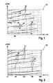
- FIG. 1 shows a pressure / flow characteristics for a pressure control valve according to the prior art.
- FIG. 1 shows a pressure / flow characteristic field 10, in which the pressure, ie the system pressure, which is applied to a high-pressure accumulator (common rail) of a high-pressure accumulator injection system, is plotted against the flow of the pressure control valve in l / h.
- the pressure ie the system pressure
- a high-pressure accumulator common rail
- a high-pressure accumulator injection system for constant pressure control valve currents are different characteristic curves (pressure over flow) 12, each characterized by an area in which there is an instability 14.
- the instability 14 is characterized in that, for a first operating point A and a second operating point B, a flow value is assigned a plurality of system pressure values, ie an undefined state of the pressure control valve is present.
- the representation according to FIG. 2 is a pressure / flow chart 10 can be seen, which is included for a proposed invention pressure control valve.
- characteristic curves are also shown here 12, however, in contrast to the instabilities 14 in the characteristic curves 12 according to FIG. 1 characterized by continuous gradients 16.
- FIG. 3 shows a section through the inventively proposed pressure control valve.
- FIG. 3 shown in section pressure control valve 20 comprises a secured to a housing 22, for example via a support ring 68 mounting member 74 with external thread.
- this mounting element 74 which is fixed on the circumference of the housing 22 of the inventive proposed pressure control valve 20 via the support ring 68 in the axial direction, the pressure control valve 20 in a high-pressure accumulator body 72, which in the illustration FIG. 3 only partially shown attached. Due to the screw connection between an internal thread in the high-pressure reservoir body 72 at the mounting location, a pressure-tight connection between the pressure regulating valve 20 proposed according to the invention and the interior of the high-pressure reservoir body 72 (common rail) takes place. In this system pressures of up to 2000 bar and more prevail.
- the system pressure p is in the high-pressure accumulator body 72 by a in FIG. 3 not shown high-pressure pumping unit, such as maintained via a high-pressure pump, regardless of the speed of a fuel to be supplied to internal combustion engine.
- FIG. 3 shows that the housing 22 of the present invention proposed pressure control valve 20, an electrical connection 24 is formed for electrical contacting of the present invention proposed pressure control valve 20.
- This insert limits the stroke of an anchor plate 34 of an armature assembly 32, which further comprises an anchor bolt 50 extending through an anchor bolt bore 52 of the housing 22 of the present invention proposed pressure control valve 20.
- the insert 26 is sealed by a first seal 28 against the housing 22 of the present invention proposed pressure control valve 20.
- the armature plate 34 accommodated on the anchor bolt 50 of the armature assembly 32 has a plan side 36 which assigns an end face 38 of the housing 22 of the pressure control valve 20.
- the plan side 36 of the armature plate 34 of the armature assembly 32 is acted upon by a compression spring 30 which is received in a bore of the end face 38 of the housing 22 of the pressure control valve 20.
- a magnetic coil 46 In the housing 22 of the pressure control valve 20 is further a magnetic coil 46, the of an embedding 44 enclosed in the housing 22 of the pressure control valve 20 is embedded. This in FIG.
- This reduced volume 40 represents a Abgresraum in which the volume discharged from the high-pressure region of the high-pressure accumulator body 72 when opening a valve element 54 occurs and this reduced volume 40 accordingly fills.
- a reduction of this volume between the armature assembly 32 and the end face 38 of the housing 22 and its filling with the high-pressure side controlled medium medium is possible to enter this volume, but due to the reduced volume 40 and due to the thereby reduced hydraulic Forces to a better stability of the pressure control valve 20, especially at elevated counter pressures leads.
- the filling of the previously existing air gap between the plane side 36 of the anchor plate 34 and the end face 38 of the housing 22 by an amagnetic material, ie the filling volume 42, can be achieved by either the plan side 36 of the anchor plate 34 or the end face 38th of the housing 22, a film or a coating is applied.
- This coating or film can be applied on the flat side 36 of the anchor plate 34 and / or on the end face 38 of the housing 22.
- the remaining residual air gap on the closed pressure control valve 20 can thereby assume an extremely low value.
- the anchor bolt 50 of the armature assembly 32 extends through the anchor bolt bore 52 in the housing 22 of the present invention proposed pressure control valve 20.
- the high pressure storage body 72 zu flode tip of the anchor bolt 52 is conical and actuates a valve member 54, which in the in FIG. 3 illustrated embodiment of the invention proposed pressure control valve 20 is designed as a ball.
- the valve element 54 is placed in its seat 56, which is formed in a seat ring 58.
- the seat ring 58 is embodied at the end of the housing 22 of the pressure regulating valve 20 proposed according to the invention, which lies opposite the cavity, ie the area of the high-pressure accumulator 52 acted upon by system pressure p.
- a channel 60 extends, via which flows from the cavity of the high-pressure accumulator body (common rail) fuel via a filter 62.
- the pressure accumulator body 72 relieves pressure.
- the valve element 74 is open via the channel 60, the seat 56, the volume of fuel diverted in the discharge lines 70 is returned to the tank of the high-pressure accumulator injection system via a low-pressure return.
- the return can not be returned directly into the tank, but are fed back to a possibly provided in fuel injection systems prefeed pump, which generates higher back pressures.
- a disk 64 may be connected upstream to compensate for manufacturing tolerances. Furthermore, located on the peripheral surface of the housing 22 of the pressure regulating valve 20 between the Abêttechnisch 70 and the support ring 68 for fixing the mounting member 74, a second seal further.
- the greater robustness and the avoidance of points of discontinuity and instabilities 14 in the characteristic curve 12 are achieved by the volume previously present at pressure regulating valves 20 between the plane side 36 of the anchor plate 34 of the end face 38 of the housing 22 through the filling volume 42, which is preferably represented by an amagnetic material, is reduced. Due to the reduced volume 40, which is then still filled by the discarded medium, a significant reduction of the hydraulic forces, which otherwise in volume between the armature plate 34 of the end face 38 of the housing 22 is effective would be achievable, which in turn favors the precision of actuation of the armature assembly 32.
- the remaining reduced volume 40 between the flat side 36 of the armature plate 34 and the end face 38 of the housing 22 of Pressure control valve 20 filled with the filling volume 42 of non-magnetic material.
- This filling volume 42 can be realized either in the form of a coating or in the form of the introduction of a film or the like.
- the measure of the formation of a reduced volume 40 can be taken together with the introduction of a filling volume 42 between the planar side 36 of the anchor plate and the end face 38 of the housing 22, or it can only a reduction of the volume 40 are performed, as well as an introduction of the Filling volume 42 between the flat side 36 of the anchor plate and the end face 38 of the housing 22.
- the compression spring 30 and the spring which acts on the anchor plate 34
- only one of these two springs may be present, ie either only the compression spring 30 or only the anchor plate 34 acting on its back, inserted into the insert 26 spring. In the Fig. 3 both possible installation positions are reproduced.
- the reduction of the volume 40 as well as the introduction of the filling volume 42 of non-magnetic material can also be realized on solenoid valves which are used to actuate fuel injectors on fuel injection systems, such as high-pressure accumulator injection systems (common rail).
Landscapes
- Engineering & Computer Science (AREA)
- Chemical & Material Sciences (AREA)
- Combustion & Propulsion (AREA)
- Mechanical Engineering (AREA)
- General Engineering & Computer Science (AREA)
- Physics & Mathematics (AREA)
- Electromagnetism (AREA)
- Fuel-Injection Apparatus (AREA)
Description
-
DE 102 14 084 A1 bezieht sich auf ein einstellbares Druckregelventil für Kraftstoffeinspritzsysteme. Das Kraftstoffeinspritzsystem umfasst einen Hochdruckspeicherraum, der über ein Hochdruckförderaggregat mit unter hohem Druck stehendem Kraftstoff beaufschlag ist und welcher Kraftstoffinjektoren mit Kraftstoff versorgt. Dem Hochdruckförderaggregat ist ein Druckregelventil zugeordnet, das zwischen einer Hochdruckseite und einer Niederdruckseite angeordnet ist und ein Ventilelement umfasst, welches über einen elektrischen Steller ansteuerbar ist. Das Druckregelventil umfasst eine Gehäusekomponente, die einen verformbaren Bereich enthält, über den bei Montage des Druckregelventils in einem Aufnahmekörper ein Spalt L zwischen Flächen einer elektrisch ansteuerbaren Stelleranordnung einstellbar ist. -
DE 102 22 895 A1 bezieht sich auf einen Hochdruckspeicher für Kraftstoffeinspritzsysteme mit integriertem Druckregelventil. Der Hochdruckspeicherraum wird über ein Hochdruckförderaggregat mit unter Hochdruck stehendem Kraftstoff beaufschlagt und versorgt seinerseits Kraftstoffinjektoren mit Kraftstoff. Das Kraftstoffeinspritzsystem umfasst ein Druckregelventil, welches zwischen einer Hochdruckseite und einer Niederdruckseite angeordnet und über welches ein Ventilelement betätigbar ist. Das Druckregelventil wird über einen elektrischen Steller betätigt. Das Druckregelventil begrenzt mit einer Stirnseite den Niederdruckbereich am Hochdruckspeicherraum und ist über eine niederdruckseitige Abdichtung abgedichtet. - Druckregelventile kommen in den verschiedensten Anwendungen zum Einsatz und werden, wie oben aus
DE 102 14 084 A1 undDE 102 22 895 A1 geschildert, an Kraftstoffeinspritzsystemen (Common-Rail) eingesetzt. Diese Druckregelventile weisen im Druck-Durchflusskennfeld bzw. in ihrem Regelbereich Unstetigkeitsstellen und Instabilitäten auf. Insbesondere nimmt auch der Rücklaufdruck einen starken Einfluss auf die Regelbarkeit bzw. die erzielbare Regelgüte der aus dem Stand der Technik bekannten Druckregelventile. - Der vorliegenden Erfindung liegt die Aufgabe zugrunde, ein verbessertes Druckregelventil bereitzustellen, welches eine größere Robustheit gegenüber dem Auftreten von Instabilität insbesondere durch den Einfluss konstanter oder variierender Drücke auf der Niederdruckseite (Rücklaufdruck, Gegendruck) aufweist.
- Erfindungsgemäß wird vorgeschlagen, ein Volumen zwischen einem Magnetanker und einer Gehäuseplanfläche, welche sich mit dem von der Hochdruckseite abgesteuerten Medium, wie zum Beispiel Kraftstoff, füllt, zu verkleinern. Dadurch wird die Stabilität des Druckregelventiles insbesondere bei erhöhtem Gegendruck verbessert, da aufgrund des geringeren Volumens wirksame hydraulische Kräfte reduziert sind, die bei bisher eingesetzten aus dem Stand der Technik bekannten Druckregelventilen die Instabilitäten verursachen. Um das Volumen, welches die Druck-Stromkennlinie eines Druckregelventiles beeinflusst und in das abgesteuerte Menge eintritt und in welchem hydraulische Kräfte auftreten, zu verringern und trotz geringem Restluftspalt so wie bisher gestalten zu können, wird das Volumen zwischen dem Magnetanker und der oben stehend erwähnten Gehäuseplanfläche mit einem nicht-magnetischen Material aufgefüllt. Die Robustheit gegen das Auftreten von Instabilitäten wird dadurch weiter erhöht.
- Das Ausfüllen des Restluftspaltes zwischen dem Magnetanker und der oben stehend bereits erwähnten Gehäuseplanfläche des Druckregelventiles, insbesondere des die Magnetspule aufnehmenden Magnetkernes erfolgt zum Beispiel durch Aufbringen oder Einlegen einer Folie. Daneben kann auch eine Beschichtung sowohl auf der der Gehäuseplanfläche zuweisenden Stirnseite des Ankers als auch auf der Gehäuseplanfläche selbst aufgebracht werden. Der erfindungsgemäß vorgeschlagenen Lösung folgend wird eine Entkopplung zwischen dem Volumen um die Ankerplatte der Ankerbaugruppe des Druckregelventiles und dem Volumen, in dem das Medium, wie zum Beispiel unter Systemdruck stehender Kraftstoff, aus dem Hochdruckbereich abgesteuert wird, hergestellt.
- Das erfindungsgemäß vorgeschlagene Druckregelventil zeichnet sich gegenüber aus dem Stand der Technik bekannten Druckregelventilen, wie oben stehend kurz skizziert, dadurch aus, dass einerseits das Volumen zwischen Magnetanker und Gehäuseplanfläche verkleinert ist, in das das von der Hochdruckseite her abgesteuerte Medium abströmt und/oder andererseits dieses bereits verkleinerte Volumen zwischen Magnetanker und Gehäuseplanfläche mit einem nicht-magnetischen Material verfüllt ist. Dies bedeutet, dass im Idealfall das verkleinerte Volumen zwischen Gehäuseplanfläche und Planseite des Magnetankers bei geschlossenem Ventil zu Null wird, so dass Instabilitäten erheblich reduziert werden können.
- Anhand der Zeichnungen wird die Erfindung nachstehend eingehender beschrieben.
- Es zeigt:
- Figur 1
- ein Druck-/Durchflusskennfeld eines Druckregelventils gemäß dem Stand der Technik bei einem anliegenden Gegendruck von etwa 5 bar,
- Figur 2
- das Druck-/Durchflusskennfeld eines erfindungsgemäß vorgeschlagenen Druckregelventils bei einem anliegenden Gegendruck zwischen 5 und 6 bar und
- Figur 3
- einen Schnitt durch das erfindungsgemäß vorgeschlagene Druckregelventil.
-
Figur 1 zeigt ein Druck-/Durchflusskennfeld für ein Druckregelventil gemäß dem Stand der Technik. - Aus der Darstellung gemäß
Figur 1 geht ein Druck-/Durchflusskennfeld 10 hervor, in dem der Druck, d. h. der Systemdruck, mit welchem ein Hochdruckspeicher (Common-Rail) eines Hochdruckspeichereinspritzsystems beaufschlagt ist, über dem Durchfluss des Druckregelventiles in l/h aufgetragen ist. Für konstante Druckregelventilströme stellen sich unterschiedliche Kennlinienverläufe (Druck über Durchfluss) 12 ein, die jeweils durch einen Bereich gekennzeichnet sind, in dem eine Instabilität 14 vorliegt. Die Instabilität 14 ist dadurch charakterisiert, dass für einen ersten Betriebspunkt A sowie einen zweiten Betriebspunkt B einem Durchflusswert mehrere Systemdruckwerte zugeordnet sind, d. h. ein undefinierter Zustand des Druckregelventiles vorliegt. - Der Darstellung gemäß
Figur 2 ist ein Druck-/Durchflusskennfeld 10 zu entnehmen, welches für ein erfindungsgemäß vorgeschlagenes Druckregelventil aufgenommen ist. Analog zur Darstellung gemäßFigur 1 sind auch hier Kennlinienverläufe 12 dargestellt, die sich jedoch im Gegensatz zu den Instabilitäten 14 in den Kennlinienverläufen 12 gemäßFigur 1 durch stetige Verläufe 16 auszeichnen. Es existiert ein kontinuierlicher stetiger Verlauf der Kennlinien, so dass bei einem anliegenden Gegendruck von mindestens 5 bar einem Wert für den Systemdruck p im Wesentlichen ein Wert für einen entsprechenden Durchfluss in l/h zugeordnet wird. Dies bedeutet, dass die Durchflussmenge für jeden Systemdruck entsprechend den Kennlinienverläufen 12 exakt definiert ist, d. h. das erfindungsgemäß vorgeschlagene Druckregelventil wesentlich stabiler zu stellen ist als das aus dem Stand der Technik bekannte Druckregelventil, dessen Instabilitäten auf den Kennlinienverläufen 12 ausFigur 1 hervorgehen. -
Figur 3 zeigt einen Schnitt durch das erfindungsgemäß vorgeschlagene Druckregelventil. - Ein in
Figur 3 im Schnitt dargestelltes Druckregelventil 20 umfasst ein an einem Gehäuse 22 zum Beispiel über einen Abstützring 68 gesichertes Montageelement 74 mit Außengewinde. Mittels dieses Montageelementes 74, welches am Umfang des Gehäuses 22 des erfmdungsgemäß vorgeschlagenen Druckregelventiles 20 über den Abstützring 68 in axialer Richtung fixiert ist, wird das Druckregelventil 20 in einem Hochdruckspeicherkörper 72, der in der Darstellung gemäßFigur 3 nur teilweise dargestellt ist, befestigt. Aufgrund der Verschraubung zwischen einem Innengewinde im Hochdruckspeicherkörper 72 an der Montagestelle erfolgt eine druckdichte Verbindung zwischen dem erfindungsgemäß vorgeschlagenen Druckregelventil 20 und dem Inneren des Hochdruckspeicherkörpers 72 (Common-Rail). In diesem herrschen Systemdrücke von bis zu 2000 bar und mehr. Der Systemdruck p wird im Hochdruckspeicherkörper 72 durch ein inFigur 3 nicht dargestelltes Hochdruckförderaggregat, wie zum Beispiel über eine Hochdruckpumpe, unabhängig von der Drehzahl einer mit Kraftstoff zu versorgenden Verbrennungskraftmaschine aufrechterhalten. - Aus
Figur 3 geht hervor, dass am Gehäuse 22 des erfindungsgemäß vorgeschlagenen Druckregelventiles 20 ein elektrischer Anschluss 24 zur elektrischen Kontaktierung des erfindungsgemäß vorgeschlagenen Druckregelventiles 20 ausgebildet ist. Im Gehäuse 22 des erfindungsgemäß vorgeschlagenen Druckregelventiles 20 befindet sich ein Einsatz 26. Dieser Einsatz begrenzt den Hub einer Ankerplatte 34 einer Ankerbaugruppe 32, die des Weiteren einen Ankerbolzen 50 umfasst, der sich durch eine Ankerbolzenbohrung 52 des Gehäuses 22 des erfindungsgemäß vorgeschlagenen Druckregelventiles 20 erstreckt. - Der Einsatz 26 ist über eine erste Dichtung 28 gegen das Gehäuse 22 des erfindungsgemäß vorgeschlagenen Druckregelventiles 20 abgedichtet. Die am Ankerbolzen 50 der Ankerbaugruppe 32 aufgenommene Ankerplatte 34 weist eine Planseite 36 auf, die einer Stirnseite 38 des Gehäuses 22 des Druckregelventiles 20 zuweist. Die Planseite 36 der Ankerplatte 34 der Ankerbaugruppe 32 ist durch eine Druckfeder 30 beaufschlagt, die in einer Bohrung der in der Stirnseite 38 des Gehäuses 22 des Druckregelventiles 20 aufgenommen ist. Im Gehäuse 22 des Druckregelventiles 20 befindet sich des weiteren eine Magnetspule 46, die von einer Einbettung 44 umschlossen, in das Gehäuse 22 des Druckregelventiles 20 eingebettet ist. Das in
Figur 3 im Schnitt dargestellte Druckregelventil zeichnet sich dadurch aus, dass es sich bei einem Volumen, welches einerseits durch die Planseite 36 der Ankerplatte 34 und andererseits durch die Stirnseite 38 des Gehäuses 22 begrenzt ist, um ein verringertes Volumen 40 handelt. Dieses verringerte Volumen 40 stellt einen Absteuerraum dar, in dem das aus dem Hochdruckbereich des Hochdruckspeicherkörpers 72 bei Öffnen eines Ventilelementes 54 abgesteuerte Volumen eintritt und dieses verringerte Volumen 40 demzufolge befüllt. Durch eine Verkleinerung dieses Volumens zwischen der Ankerbaugruppe 32 und der Stirnseite 38 des Gehäuses 22 und dessen Befüllung mit dem von der Hochdruckseite abgesteuerten Medium ist zwar ein Eintritt von Medium in dieses Volumen möglich, was jedoch aufgrund des verringerten Volumens 40 und aufgrund der dadurch verringerten hydraulischen Kräfte zu einer besseren Stabilität des Druckregelventiles 20, insbesondere bei erhöhten Gegendrücken, führt. Dies geht aus den jeweils stetige Verläufen 16 aufweisenden Kennlinien 12 des Druck-/Durchflusskennfeldes 10 gemäßFigur 2 besonders deutlich hervor. Um einen nicht-magnetischen Spalt 48, welcher die Druck-Stromkennlinie des erfindungsgemäß vorgeschlagenen Druckregelventiles 20 bestimmt, trotz sehr geringem Luftspalt, hinreichend groß gestalten zu können, wird das verringerte Volumen 40 zwischen der Ankerplatte 34 und der Stirnseite 38 des Gehäuses 22 mit einem Füllvolumen 42 bevorzugt aus einem nicht-magnetischen Material aufgefüllt. Dadurch wird eine weitere Steigerung der Robustheit gegen das Auftreten von Instabilitäten 14 - wie anhand der Kennlinienverläufe 12 gemäßFigur 1 gezeigt - erreicht. Bei geschlossenem Druckregelventil 20 bleibt im Idealfall kein Luftspalt, der gesamte nicht-magnetische Spalt 48 wird durch nicht-magnetisches Material, d. h. das Füllvolumen 42, ausgefüllt. In der Praxis verbleibt jedoch aufgrund von Fertigungstoleranzen auch im geschlossenen Zustand des Druckregelventiles 20 ein kleiner Luftspalt, der jedoch im Vergleich zu dem Luftspalt, der bei Druckregelventilen gemäß des Standes der Technik das Volumen bildet, welches durch den abgesteuerten Kraftstoff ausgefüllt ist, erheblich reduziert ist. - Wie in
Figur 3 angedeutet, kann das Ausfüllen des bisher vorhandenen Luftspaltes zwischen der Planseite 36 der Ankerplatte 34 und der Stirnseite 38 des Gehäuses 22 durch ein amagnetisches Material, d. h. dem Füllvolumen 42, dadurch erreicht werden, dass entweder auf die Planseite 36 der Ankerplatte 34 oder die Stirnseite 38 des Gehäuses 22 eine Folie oder eine Beschichtung aufgebracht wird. Diese Beschichtung bzw. Folie kann auf der Planseite 36 der Ankerplatte 34 und/oder auf der Stirnseite 38 des Gehäuses 22 aufgebracht werden. Der verbleibende Restluftspalt am geschlossenen Druckregelventil 20 kann dadurch einen äußerst geringen Wert annehmen. - Wie aus der Darstellung gemäß
Figur 3 weiter hervorgeht, erstreckt sich der Ankerbolzen 50 der Ankerbaugruppe 32 durch die Ankerbolzenbohrung 52 im Gehäuse 22 des erfindungsgemäß vorgeschlagenen Druckregelventiles 20. Die dem Hochdruckspeicherkörper 72 zuweisende Spitze des Ankerbolzens 52 ist konisch ausgebildet und betätigt ein Ventilelement 54, welches in der inFigur 3 dargestellten Ausführungsform des erfindungsgemäß vorgeschlagenen Druckregelventiles 20 als Kugel ausgebildet ist. Über den Ankerbolzen 50 wird das in dieser Ausführungsform kugelförmig ausgebildete Ventilelement 54 in seinen Sitz 56 gestellt, der in einem Sitzring 58 ausgebildet ist. Der Sitzring 58 ist an dem Ende des Gehäuses 22 des erfindungsgemäß vorgeschlagenen Druckregelventiles 20 ausgeführt, welches dem Hohlraum, d. h. dem mit Systemdruck p beaufschlagten Bereich des Hochdruckspeichers 52, gegenüberliegt. Durch den Sitzring 58 erstreckt sich ein Kanal 60, über den aus dem Hohlraum des Hochdruckspeicherkörpers (Common-Rail) Kraftstoff über ein Filtersieb 62 zuströmt. Je nachdem, welcher Systemdruck p im inneren des Hochdruckspeicherkörpers 72 herrscht, wird bei Überschreiten eines bestimmten Höchstdruckes, so zum Beispiel bei Druckpulsationen über das Druckregelventil 20 gemäß der Schnittdarstellung inFigur 3 , der Hochdruckspeicherkörper 72 druckentlastet. Bei geöffnetem Ventilelement 74 über den Kanal 60, den Sitz 56, in Absteuerleitungen 70 abgesteuertes Kraftstoffvolumen wird über einen niederdruckseitigen Rücklauf wieder dem Tank des Hochdruckspeichereinspritzsystems zugeführt. Bei anderen Ausführungsformen von Kraftstoffeinspritzsystemen kann der Rücklauf auch nicht direkt in den Tank zurückgeleitet werden, sondern nach einer in Kraftstoffeinspritzsystemen gegebenenfalls vorgesehenen Vorförderpumpe wieder eingespeist werden, welche höhere Gegendrücke erzeugt. - Aus der Darstellung gemäß
Figur 3 geht des weiteren hervor, dass zwischen dem Sitzring 58, in dem der Sitz 56 für das hier kugelförmig ausgebildete Ventilelement 54 ausgebildet ist, eine Scheibe 64 vorgeschaltet sein kann, um Fertigungstoleranzen auszugleichen. Des weiteren befindet sich an der Umfangsfläche des Gehäuses 22 des Druckregelventiles 20 zwischen der Absteuerleitung 70 und dem Abstützring 68 zur Fixierung des Montageelementes 74 eine weitere zweite Dichtung. - Bei dem erfindungsgemäß vorgeschlagenen Druckregelventil 20 wird die größere Robustheit und das Vermeiden von Unstetigkeitsstellen und Instabilitäten 14 im Kennlinienverlauf 12 dadurch erreicht, dass das bisher an Druckregelventilen 20 vorhandene Volumen zwischen der Planseite 36 der Ankerplatte 34 der Stirnseite 38 des Gehäuses 22 durch das Füllvolumen 42, welches bevorzugt durch ein amagnetisches Material dargestellt wird, reduziert wird. Aufgrund des verringerten Volumens 40, welches dann noch durch das abgesteuerte Medium ausgefüllt wird, ist eine erhebliche Verringerung der hydraulischen Kräfte, die andernfalls im Volumen zwischen der Ankerplatte 34 der Stirnseite 38 des Gehäuses 22 wirksam werden würden erzielbar, was wiederum die Präzision der Betätigung der Ankerbaugruppe 32 begünstigt. Um den nicht-magnetischen Spalt 48, welcher die Druck-Stromkennlinie des erfindungsgemäß vorgeschlagenen Druckregelventiles 20 bestimmt, trotz kleinem Luftspalt hinreichend groß gestalten zu können, wird das verbliebene verringerte Volumen 40 zwischen der Planseite 36 der Ankerplatte 34 und der Stirnseite 38 des Gehäuses 22 des Druckregelventiles 20 mit dem Füllvolumen 42 aus amagnetischem Material aufgefüllt. Dieses Füllvolumen 42 kann entweder in Form einer Beschichtung oder in Form des Einbringens einer Folie oder dergleichen realisiert sein. Wenn das erfindungsgemäß vorgeschlagene Druckregelventil 20 geschlossen ist, besteht zwischen der Stirnseite 38 des Gehäuses 22 und der Planseite 36 der Ankerplatte 34 ein verbleibender nicht-magnetischer Spalt, der durch das Füllvolumen 42 so reduziert ist; dass hydraulische Kräfte nicht zu den in Zusammenhang mit
Figur 1 dargestellten Instabilitäten 14 am Druckregelventil 20 führen können. Befindet sich das erfindungsgemäß vorgeschlagene Druckregelventil 20 gemäßFigur 3 in seiner offenen Position, so ist die Ankerbaugruppe 32 aus Ankerbolzen 50 und Ankerplatte 34 in Öffnungsrichtung verschoben, so dass sich bei offenstehendem Druckregelventil 20 ein etwas vergrößertes Volumen zwischen der Planseite 36 der Ankerplatte 34 und der Stirnseite 38 des Gehäuses 22 des Druckregelventiles 20 ergibt. Dieses Volumen ist jedoch erheblich reduziert. Erfindungsgemäß kann die Maßnahme der Ausbildung eines verringerten Volumens 40 zusammen mit dem Einbringen eines Füllvolumens 42 zwischen die Planseite 36 der Ankerplatte und die Stirnseite 38 des Gehäuses 22 ergriffen werden, oder es kann lediglich eine Verringerung des Volumens 40 durchgeführt werden, wie auch ein Einbringen des Füllvolumens 42 zwischen die Planseite 36 der Ankerplatte und die Stirnseite 38 des Gehäuses 22. Anstelle der beiden in der Darstellung gemäßFigur 3 dargestellten Federn, der Druckfeder 30 und der Feder, die die Ankerplatte 34 beaufschlagt, kann auch lediglich eine dieser beiden Federn vorhanden sein, d.h. entweder nur die Druckfeder 30 oder nur die die Ankerplatte 34 an ihrer Rückseite beaufschlagende, in den Einsatz 26 eingelassene Feder. In derFig. 3 sind beide möglichen Einbaupositionen wiedergegeben. - Die Verringerung des Volumens 40 sowie das Einbringen des Füllvolumens 42 aus nicht-magnetischem Material können auch an Magnetventilen verwirklicht werden, die zur Betätigung von Kraftstoffinjektoren an Kraftstoffeinspritzsystemen, wie zum Beispiel Hochdruckspeichereinspritzsystemen (Common-Rail) eingesetzt werden.
Claims (9)
- Druckregelventil (20) für einen Hochdruckspeicherkörper (72) oder eine Hochdruckförderpumpe eines Kraftstoffeinspritzsystems, mit einem Gehäuse (22), einer Ankerbaugruppe (32), mit einer Ankerplatte (34) und einem Ankerbolzen (50), wobei im Hochdruckspeicherkörper (72) ein Systemdruck p von mindestens > 1500 bar herrscht, während im Gehäuse (22) des Druckregelventils (20) der Druck durch den herrschenden Druck in einer Absteuerleitung (70) bestimmt ist, wobei die Ankerplatte (34) und eine Stirnseite (38) des Gehäuses (22) ein mit aus dem Hochdruckspeicherkörper (72) abgesteuertem Medium befüllbares Volumen (40) darstellen, dadurch gekennzeichnet, dass das Volumen (40) durch ein Füllvolumen (42) verringert ist, und das Druckregelventil (20) zu einer Druckentlastung des Hochdruckspeicherkörpers (72) bei Überschreiten eines bestimmten Höchstdrucks durch den Systemdruck p ausgebildet ist.
- Druckregelventil (20) gemäß Anspruch 1, dadurch gekennzeichnet, dass das Füllvolumen (42) ein amagnetisches Material ist.
- Druckregelventil (20) gemäß Anspruch 1, dadurch gekennzeichnet, dass das Füllvolumen (42) zwischen eine Planseite (36) der Ankerplatte (34) und eine Stirnseite (38) des Gehäuses (22) eingebracht ist.
- Druckregelventil (20) gemäß Anspruch 2, dadurch gekennzeichnet, dass das Füllvolumen (42) als Folie oder als Beschichtung ausgebildet ist.
- Druckregelventil (20) gemäß Anspruch 3, dadurch gekennzeichnet, dass das als Folie oder als Beschichtung ausgebildete Füllvolumen (42) auf eine Planseite (36) der Ankerplatte (34) aufgebracht ist, oder zwischen die Planseite (36) und die Stirnseite (38) des Gehäuses (22) eingelegt ist.
- Druckregelventil (20) gemäß Anspruch 3, dadurch gekennzeichnet, dass das als Folie oder als Beschichtung ausgebildete Füllvolumen (42) auf die Stirnseite (38) des Gehäuses (22) aufgebracht ist.
- Druckregelventil (20) gemäß Anspruch 3, dadurch gekennzeichnet, dass zwischen dem Füllvolumen (42) und der Planseite (36) der Ankerplatte (34) oder der Stirnseite (38) des Gehäuses (22) ein nicht-magnetischer Spalt (48) verbleibt.
- Druckregelventil (20) gemäß Anspruch 1, dadurch gekennzeichnet, dass ein Volumen in einem Einsatz (26) des Gehäuses (22), in dem die Ankerplatte (34) der Ankerbaugruppe (32) aufgenommen ist, von dem verringerten Volumen (40) in das Medium aus dem Hochdruckspeicher (42) abgesteuert wird, entkoppelt ist.
- Druckregelventil (20) gemäß einem oder mehreren der vorhergehenden Ansprüche, dadurch gekennzeichnet, dass dieses in einem Kraftstoffeinspritzsystem, insbesondere einem Hochdruckspeichereinspritzsystem, angeordnet ist.
Applications Claiming Priority (2)
| Application Number | Priority Date | Filing Date | Title |
|---|---|---|---|
| DE102007013525A DE102007013525A1 (de) | 2007-03-21 | 2007-03-21 | Druckregelventil |
| PCT/EP2008/053140 WO2008113776A1 (de) | 2007-03-21 | 2008-03-17 | Druckregelventil |
Publications (2)
| Publication Number | Publication Date |
|---|---|
| EP2137400A1 EP2137400A1 (de) | 2009-12-30 |
| EP2137400B1 true EP2137400B1 (de) | 2013-05-29 |
Family
ID=39590403
Family Applications (1)
| Application Number | Title | Priority Date | Filing Date |
|---|---|---|---|
| EP08717877.8A Active EP2137400B1 (de) | 2007-03-21 | 2008-03-17 | Druckregelventil |
Country Status (7)
| Country | Link |
|---|---|
| US (1) | US20110220740A1 (de) |
| EP (1) | EP2137400B1 (de) |
| JP (1) | JP2010521621A (de) |
| CN (1) | CN101641514A (de) |
| DE (1) | DE102007013525A1 (de) |
| ES (1) | ES2412232T3 (de) |
| WO (1) | WO2008113776A1 (de) |
Families Citing this family (13)
| Publication number | Priority date | Publication date | Assignee | Title |
|---|---|---|---|---|
| DE102009026477A1 (de) | 2009-05-26 | 2010-12-02 | Robert Bosch Gmbh | Druckregelventil, insbesondere für einen Hochdruckspeicherkörper eines Kraftstoffeinspritzsystems |
| DE102010026501A1 (de) | 2010-07-07 | 2012-01-12 | Kendrion Binder Magnete Gmbh | Druckregelventil |
| DE102011013702B4 (de) | 2011-03-11 | 2016-02-04 | Kendrion (Villingen) Gmbh | Elektromagnetischer Aktor |
| FR2973076A1 (fr) * | 2011-03-25 | 2012-09-28 | Bosch Gmbh Robert | Regulateur de pression, dispositif d'injection diesel comportant un tel regulateur, moteur diesel comportant un tel dispositif d'injection et vehicule comportant un tel moteur |
| RU2513051C2 (ru) * | 2012-06-26 | 2014-04-20 | Федеральное государственное бюджетное образовательное учреждение высшего профессионального образования "Московский автомобильно-дорожный государственный технический университет (МАДИ)" | Топливный насос для дизеля (варианты) |
| DE102012214920A1 (de) | 2012-08-22 | 2014-02-27 | Continental Automotive Gmbh | Dämpfungsoberfläche an Ventilkomponenten |
| DE102012216534A1 (de) * | 2012-09-17 | 2014-03-20 | Robert Bosch Gmbh | Druckregelventil für ein Kraftstoffeinspritzsystem |
| JP6076718B2 (ja) * | 2012-12-05 | 2017-02-08 | ボッシュ株式会社 | 圧力制御弁 |
| CN103277548B (zh) * | 2013-05-31 | 2015-09-02 | 龙口龙泵燃油喷射有限公司 | 一种共轨管保护阀 |
| FR3009344B1 (fr) * | 2013-07-31 | 2015-08-07 | Delphi Technologies Holding | Agencement integre d'une vanne haute pression et d'une rampe d'injection |
| JP6201504B2 (ja) * | 2013-08-09 | 2017-09-27 | 株式会社デンソー | 燃料噴射装置 |
| FR3061935A1 (fr) | 2017-01-18 | 2018-07-20 | Robert Bosch Gmbh | Regulateur de pression pour une rampe commune d'une installation d'injection haute pression |
| BR112021004648B1 (pt) * | 2018-09-12 | 2022-12-13 | Smc Corporation | Dispositivo de controle de descarga de fluido comprimido |
Family Cites Families (14)
| Publication number | Priority date | Publication date | Assignee | Title |
|---|---|---|---|---|
| GB1293492A (en) * | 1971-05-28 | 1972-10-18 | Pierburg Autogeraetebau K G A | Electromagnetic fuel valves for internal combustion engines and method of adjusting the valve stroke |
| JPS60153466A (ja) * | 1984-01-23 | 1985-08-12 | Nippon Denso Co Ltd | 電磁式燃料噴射弁 |
| US4883252A (en) * | 1989-01-23 | 1989-11-28 | Colt Industries Inc. | Electromagnet and valve assembly |
| IT1257958B (it) * | 1992-12-29 | 1996-02-19 | Mario Ricco | Dispositivo di registrazione di una valvola di dosaggio a comando elettromagnetico, per un iniettore di combustibile |
| JPH07279792A (ja) * | 1994-04-01 | 1995-10-27 | Toyota Motor Corp | 電磁弁装置 |
| JP4277158B2 (ja) * | 2000-04-11 | 2009-06-10 | 株式会社デンソー | 電磁弁及びそれを用いた燃料噴射装置 |
| US6499668B2 (en) * | 2000-12-29 | 2002-12-31 | Siemens Automotive Corporation | Modular fuel injector having a surface treatment on an impact surface of an electromagnetic actuator and having a terminal connector interconnecting an electromagnetic actuator with an electrical terminal |
| DE10131201A1 (de) * | 2001-06-28 | 2003-01-16 | Bosch Gmbh Robert | Magnetventil zur Steuerung eines Einspritzventils einer Brennkraftmaschine |
| DE10131199A1 (de) * | 2001-06-28 | 2003-01-16 | Bosch Gmbh Robert | Magnetventil zur Steuerung eines Einspritzventils einer Brennkraftmaschine |
| US20030178509A1 (en) * | 2002-03-19 | 2003-09-25 | Visteon Global Technologies, Inc. | Fuel injector with flux washer |
| DE10214084A1 (de) | 2002-03-28 | 2003-10-30 | Bosch Gmbh Robert | Einstellbares Druckregelventil für Kraftstoffeinspritzsysteme |
| DE10222895A1 (de) | 2002-05-23 | 2003-12-11 | Bosch Gmbh Robert | Hochdruckspeicher für Kraftstoffeinspritzsysteme mit integriertem Druckregelventil |
| US6606977B1 (en) * | 2002-09-17 | 2003-08-19 | Stanadyne Corporation | Fluid delivery line geometry optimization |
| US7028928B2 (en) * | 2002-12-02 | 2006-04-18 | Caterpillar Inc. | Hard coating of an impact surface of a solenoid actuator and fuel injector using same |
-
2007
- 2007-03-21 DE DE102007013525A patent/DE102007013525A1/de not_active Withdrawn
-
2008
- 2008-03-17 CN CN200880009116.4A patent/CN101641514A/zh active Pending
- 2008-03-17 JP JP2009554013A patent/JP2010521621A/ja active Pending
- 2008-03-17 US US12/532,325 patent/US20110220740A1/en not_active Abandoned
- 2008-03-17 WO PCT/EP2008/053140 patent/WO2008113776A1/de not_active Ceased
- 2008-03-17 ES ES08717877T patent/ES2412232T3/es active Active
- 2008-03-17 EP EP08717877.8A patent/EP2137400B1/de active Active
Also Published As
| Publication number | Publication date |
|---|---|
| CN101641514A (zh) | 2010-02-03 |
| WO2008113776A1 (de) | 2008-09-25 |
| DE102007013525A1 (de) | 2008-09-25 |
| EP2137400A1 (de) | 2009-12-30 |
| ES2412232T3 (es) | 2013-07-10 |
| JP2010521621A (ja) | 2010-06-24 |
| US20110220740A1 (en) | 2011-09-15 |
Similar Documents
| Publication | Publication Date | Title |
|---|---|---|
| WO2008113776A1 (de) | Druckregelventil | |
| EP2238338B1 (de) | Kraftstoffsystem einer Brennkraftmaschine | |
| EP2684200B1 (de) | Elektromagnetischer aktor | |
| EP2016278B1 (de) | Druckregelventil mit notfahr- und belüftungsfunktion | |
| EP1509694B1 (de) | Hochdruckspeicher für kraftstoffeinspritzsysteme mit integriertem druckregelventil | |
| EP1492954A1 (de) | Einstellbares druckregelventil für kraftstoffeinspritzsysteme | |
| EP1203151B1 (de) | Zweistufiges magnetventil für einen injektor von brennkarftmaschinen | |
| DE102014217441A1 (de) | Elektromagnetisch betätigbares Proportionalventil | |
| DE102015226070A1 (de) | Kraftstoffinjektor | |
| EP1799999B1 (de) | Kraftstoffsystem für eine brennkraftmaschine | |
| EP2413333B1 (de) | Druckregelventil | |
| EP2895732A1 (de) | Druckregelventil für ein kraftstoffeinspritzsystem | |
| DE102007001365A1 (de) | Injektor mit Steuer- und Schaltkammer | |
| DE102004020941B9 (de) | Druckregelanordnung | |
| WO2016134930A1 (de) | Teildruckausgeglichenes druckregelventil für einen hochdruckspeicher | |
| DE102015214816A1 (de) | Hochdruckanordnung | |
| DE102024204026A1 (de) | Absperrventileinrichtung für ein Brennstoffversorgungssystem zur Versorgung einer Brennkraftmaschine mit gasförmigem Brennstoff, beispielsweise mit Wasserstoff, und Druckregeleinrichtung sowie Tankeinrichtung für das Brennstoffversorgungssystem | |
| DE102014221660A1 (de) | Verfahren zur Regelung der Fördermenge einer Hochdruckpumpe sowie Hochdruckpumpe | |
| DE102022205162A1 (de) | Kolbenpumpe, insbesondere Kraftstoff-Hochdruckpumpe, sowie Einlassventil für eine Kolbenpumpe | |
| EP2659127A1 (de) | Druck-schaltventil für ein kraftstoffeinspritzsystem einer brennkraftmaschine | |
| DE10059399A1 (de) | Vorrichtung zur Verbesserung der Einspritzabfolge bei Kraftstoffeinspritzsystemen | |
| DE102007017126A1 (de) | Einspritzmodul | |
| DE102018208253A1 (de) | Hochdruckpumpe für ein Kraftstoffeinspritzsystem, Verfahren zum Betreiben einer Hochdruckpumpe | |
| EP3283757A1 (de) | Druckregelventil mit integriertem drucksensor | |
| EP1694957A1 (de) | Druckausgeglichenes, direktgesteuertes ventil |
Legal Events
| Date | Code | Title | Description |
|---|---|---|---|
| PUAI | Public reference made under article 153(3) epc to a published international application that has entered the european phase |
Free format text: ORIGINAL CODE: 0009012 |
|
| 17P | Request for examination filed |
Effective date: 20091021 |
|
| AK | Designated contracting states |
Kind code of ref document: A1 Designated state(s): AT BE BG CH CY CZ DE DK EE ES FI FR GB GR HR HU IE IS IT LI LT LU LV MC MT NL NO PL PT RO SE SI SK TR |
|
| DAX | Request for extension of the european patent (deleted) | ||
| 17Q | First examination report despatched |
Effective date: 20100714 |
|
| GRAP | Despatch of communication of intention to grant a patent |
Free format text: ORIGINAL CODE: EPIDOSNIGR1 |
|
| GRAS | Grant fee paid |
Free format text: ORIGINAL CODE: EPIDOSNIGR3 |
|
| GRAA | (expected) grant |
Free format text: ORIGINAL CODE: 0009210 |
|
| AK | Designated contracting states |
Kind code of ref document: B1 Designated state(s): AT BE BG CH CY CZ DE DK EE ES FI FR GB GR HR HU IE IS IT LI LT LU LV MC MT NL NO PL PT RO SE SI SK TR |
|
| REG | Reference to a national code |
Ref country code: GB Ref legal event code: FG4D Free format text: NOT ENGLISH |
|
| REG | Reference to a national code |
Ref country code: CH Ref legal event code: EP |
|
| REG | Reference to a national code |
Ref country code: AT Ref legal event code: REF Ref document number: 614567 Country of ref document: AT Kind code of ref document: T Effective date: 20130615 |
|
| REG | Reference to a national code |
Ref country code: IE Ref legal event code: FG4D Free format text: LANGUAGE OF EP DOCUMENT: GERMAN |
|
| REG | Reference to a national code |
Ref country code: ES Ref legal event code: FG2A Ref document number: 2412232 Country of ref document: ES Kind code of ref document: T3 Effective date: 20130710 |
|
| REG | Reference to a national code |
Ref country code: DE Ref legal event code: R096 Ref document number: 502008010022 Country of ref document: DE Effective date: 20130725 |
|
| REG | Reference to a national code |
Ref country code: LT Ref legal event code: MG4D |
|
| PG25 | Lapsed in a contracting state [announced via postgrant information from national office to epo] |
Ref country code: SI Free format text: LAPSE BECAUSE OF FAILURE TO SUBMIT A TRANSLATION OF THE DESCRIPTION OR TO PAY THE FEE WITHIN THE PRESCRIBED TIME-LIMIT Effective date: 20130529 Ref country code: LT Free format text: LAPSE BECAUSE OF FAILURE TO SUBMIT A TRANSLATION OF THE DESCRIPTION OR TO PAY THE FEE WITHIN THE PRESCRIBED TIME-LIMIT Effective date: 20130529 Ref country code: IS Free format text: LAPSE BECAUSE OF FAILURE TO SUBMIT A TRANSLATION OF THE DESCRIPTION OR TO PAY THE FEE WITHIN THE PRESCRIBED TIME-LIMIT Effective date: 20130929 Ref country code: SE Free format text: LAPSE BECAUSE OF FAILURE TO SUBMIT A TRANSLATION OF THE DESCRIPTION OR TO PAY THE FEE WITHIN THE PRESCRIBED TIME-LIMIT Effective date: 20130529 Ref country code: GR Free format text: LAPSE BECAUSE OF FAILURE TO SUBMIT A TRANSLATION OF THE DESCRIPTION OR TO PAY THE FEE WITHIN THE PRESCRIBED TIME-LIMIT Effective date: 20130830 Ref country code: FI Free format text: LAPSE BECAUSE OF FAILURE TO SUBMIT A TRANSLATION OF THE DESCRIPTION OR TO PAY THE FEE WITHIN THE PRESCRIBED TIME-LIMIT Effective date: 20130529 Ref country code: PT Free format text: LAPSE BECAUSE OF FAILURE TO SUBMIT A TRANSLATION OF THE DESCRIPTION OR TO PAY THE FEE WITHIN THE PRESCRIBED TIME-LIMIT Effective date: 20130930 Ref country code: NO Free format text: LAPSE BECAUSE OF FAILURE TO SUBMIT A TRANSLATION OF THE DESCRIPTION OR TO PAY THE FEE WITHIN THE PRESCRIBED TIME-LIMIT Effective date: 20130829 |
|
| REG | Reference to a national code |
Ref country code: NL Ref legal event code: VDEP Effective date: 20130529 |
|
| PG25 | Lapsed in a contracting state [announced via postgrant information from national office to epo] |
Ref country code: BG Free format text: LAPSE BECAUSE OF FAILURE TO SUBMIT A TRANSLATION OF THE DESCRIPTION OR TO PAY THE FEE WITHIN THE PRESCRIBED TIME-LIMIT Effective date: 20130829 Ref country code: PL Free format text: LAPSE BECAUSE OF FAILURE TO SUBMIT A TRANSLATION OF THE DESCRIPTION OR TO PAY THE FEE WITHIN THE PRESCRIBED TIME-LIMIT Effective date: 20130529 Ref country code: HR Free format text: LAPSE BECAUSE OF FAILURE TO SUBMIT A TRANSLATION OF THE DESCRIPTION OR TO PAY THE FEE WITHIN THE PRESCRIBED TIME-LIMIT Effective date: 20130529 |
|
| PG25 | Lapsed in a contracting state [announced via postgrant information from national office to epo] |
Ref country code: LV Free format text: LAPSE BECAUSE OF FAILURE TO SUBMIT A TRANSLATION OF THE DESCRIPTION OR TO PAY THE FEE WITHIN THE PRESCRIBED TIME-LIMIT Effective date: 20130529 |
|
| PG25 | Lapsed in a contracting state [announced via postgrant information from national office to epo] |
Ref country code: CZ Free format text: LAPSE BECAUSE OF FAILURE TO SUBMIT A TRANSLATION OF THE DESCRIPTION OR TO PAY THE FEE WITHIN THE PRESCRIBED TIME-LIMIT Effective date: 20130529 Ref country code: DK Free format text: LAPSE BECAUSE OF FAILURE TO SUBMIT A TRANSLATION OF THE DESCRIPTION OR TO PAY THE FEE WITHIN THE PRESCRIBED TIME-LIMIT Effective date: 20130529 Ref country code: SK Free format text: LAPSE BECAUSE OF FAILURE TO SUBMIT A TRANSLATION OF THE DESCRIPTION OR TO PAY THE FEE WITHIN THE PRESCRIBED TIME-LIMIT Effective date: 20130529 Ref country code: EE Free format text: LAPSE BECAUSE OF FAILURE TO SUBMIT A TRANSLATION OF THE DESCRIPTION OR TO PAY THE FEE WITHIN THE PRESCRIBED TIME-LIMIT Effective date: 20130529 |
|
| PG25 | Lapsed in a contracting state [announced via postgrant information from national office to epo] |
Ref country code: RO Free format text: LAPSE BECAUSE OF FAILURE TO SUBMIT A TRANSLATION OF THE DESCRIPTION OR TO PAY THE FEE WITHIN THE PRESCRIBED TIME-LIMIT Effective date: 20130529 Ref country code: NL Free format text: LAPSE BECAUSE OF FAILURE TO SUBMIT A TRANSLATION OF THE DESCRIPTION OR TO PAY THE FEE WITHIN THE PRESCRIBED TIME-LIMIT Effective date: 20130529 |
|
| PLBE | No opposition filed within time limit |
Free format text: ORIGINAL CODE: 0009261 |
|
| STAA | Information on the status of an ep patent application or granted ep patent |
Free format text: STATUS: NO OPPOSITION FILED WITHIN TIME LIMIT |
|
| 26N | No opposition filed |
Effective date: 20140303 |
|
| REG | Reference to a national code |
Ref country code: DE Ref legal event code: R097 Ref document number: 502008010022 Country of ref document: DE Effective date: 20140303 |
|
| PG25 | Lapsed in a contracting state [announced via postgrant information from national office to epo] |
Ref country code: LU Free format text: LAPSE BECAUSE OF FAILURE TO SUBMIT A TRANSLATION OF THE DESCRIPTION OR TO PAY THE FEE WITHIN THE PRESCRIBED TIME-LIMIT Effective date: 20140317 |
|
| REG | Reference to a national code |
Ref country code: CH Ref legal event code: PL |
|
| REG | Reference to a national code |
Ref country code: IE Ref legal event code: MM4A |
|
| PG25 | Lapsed in a contracting state [announced via postgrant information from national office to epo] |
Ref country code: CH Free format text: LAPSE BECAUSE OF NON-PAYMENT OF DUE FEES Effective date: 20140331 Ref country code: LI Free format text: LAPSE BECAUSE OF NON-PAYMENT OF DUE FEES Effective date: 20140331 Ref country code: IE Free format text: LAPSE BECAUSE OF NON-PAYMENT OF DUE FEES Effective date: 20140317 |
|
| REG | Reference to a national code |
Ref country code: AT Ref legal event code: MM01 Ref document number: 614567 Country of ref document: AT Kind code of ref document: T Effective date: 20140317 |
|
| PG25 | Lapsed in a contracting state [announced via postgrant information from national office to epo] |
Ref country code: AT Free format text: LAPSE BECAUSE OF NON-PAYMENT OF DUE FEES Effective date: 20140317 |
|
| PG25 | Lapsed in a contracting state [announced via postgrant information from national office to epo] |
Ref country code: MT Free format text: LAPSE BECAUSE OF FAILURE TO SUBMIT A TRANSLATION OF THE DESCRIPTION OR TO PAY THE FEE WITHIN THE PRESCRIBED TIME-LIMIT Effective date: 20130529 |
|
| REG | Reference to a national code |
Ref country code: FR Ref legal event code: PLFP Year of fee payment: 9 |
|
| PG25 | Lapsed in a contracting state [announced via postgrant information from national office to epo] |
Ref country code: MC Free format text: LAPSE BECAUSE OF FAILURE TO SUBMIT A TRANSLATION OF THE DESCRIPTION OR TO PAY THE FEE WITHIN THE PRESCRIBED TIME-LIMIT Effective date: 20130529 |
|
| PG25 | Lapsed in a contracting state [announced via postgrant information from national office to epo] |
Ref country code: CY Free format text: LAPSE BECAUSE OF FAILURE TO SUBMIT A TRANSLATION OF THE DESCRIPTION OR TO PAY THE FEE WITHIN THE PRESCRIBED TIME-LIMIT Effective date: 20130529 |
|
| PG25 | Lapsed in a contracting state [announced via postgrant information from national office to epo] |
Ref country code: TR Free format text: LAPSE BECAUSE OF FAILURE TO SUBMIT A TRANSLATION OF THE DESCRIPTION OR TO PAY THE FEE WITHIN THE PRESCRIBED TIME-LIMIT Effective date: 20130529 Ref country code: HU Free format text: LAPSE BECAUSE OF FAILURE TO SUBMIT A TRANSLATION OF THE DESCRIPTION OR TO PAY THE FEE WITHIN THE PRESCRIBED TIME-LIMIT; INVALID AB INITIO Effective date: 20080317 |
|
| REG | Reference to a national code |
Ref country code: FR Ref legal event code: PLFP Year of fee payment: 10 |
|
| PG25 | Lapsed in a contracting state [announced via postgrant information from national office to epo] |
Ref country code: BE Free format text: LAPSE BECAUSE OF NON-PAYMENT OF DUE FEES Effective date: 20140331 |
|
| REG | Reference to a national code |
Ref country code: FR Ref legal event code: PLFP Year of fee payment: 11 |
|
| PGFP | Annual fee paid to national office [announced via postgrant information from national office to epo] |
Ref country code: GB Payment date: 20200325 Year of fee payment: 13 |
|
| PGFP | Annual fee paid to national office [announced via postgrant information from national office to epo] |
Ref country code: ES Payment date: 20200421 Year of fee payment: 13 |
|
| GBPC | Gb: european patent ceased through non-payment of renewal fee |
Effective date: 20210317 |
|
| PG25 | Lapsed in a contracting state [announced via postgrant information from national office to epo] |
Ref country code: GB Free format text: LAPSE BECAUSE OF NON-PAYMENT OF DUE FEES Effective date: 20210317 |
|
| REG | Reference to a national code |
Ref country code: ES Ref legal event code: FD2A Effective date: 20220523 |
|
| PG25 | Lapsed in a contracting state [announced via postgrant information from national office to epo] |
Ref country code: ES Free format text: LAPSE BECAUSE OF NON-PAYMENT OF DUE FEES Effective date: 20210318 |
|
| PGFP | Annual fee paid to national office [announced via postgrant information from national office to epo] |
Ref country code: DE Payment date: 20250522 Year of fee payment: 18 |
|
| PGFP | Annual fee paid to national office [announced via postgrant information from national office to epo] |
Ref country code: IT Payment date: 20250331 Year of fee payment: 18 |
|
| PGFP | Annual fee paid to national office [announced via postgrant information from national office to epo] |
Ref country code: FR Payment date: 20260325 Year of fee payment: 19 |