EP2136587A2 - Systèmes de communication - Google Patents
Systèmes de communication Download PDFInfo
- Publication number
- EP2136587A2 EP2136587A2 EP09171903A EP09171903A EP2136587A2 EP 2136587 A2 EP2136587 A2 EP 2136587A2 EP 09171903 A EP09171903 A EP 09171903A EP 09171903 A EP09171903 A EP 09171903A EP 2136587 A2 EP2136587 A2 EP 2136587A2
- Authority
- EP
- European Patent Office
- Prior art keywords
- transmission
- sequence
- preamble
- interval
- communication system
- Prior art date
- Legal status (The legal status is an assumption and is not a legal conclusion. Google has not performed a legal analysis and makes no representation as to the accuracy of the status listed.)
- Withdrawn
Links
Images


Classifications
-
- H—ELECTRICITY
- H04—ELECTRIC COMMUNICATION TECHNIQUE
- H04W—WIRELESS COMMUNICATION NETWORKS
- H04W28/00—Network traffic management; Network resource management
- H04W28/16—Central resource management; Negotiation of resources or communication parameters, e.g. negotiating bandwidth or QoS [Quality of Service]
-
- H—ELECTRICITY
- H04—ELECTRIC COMMUNICATION TECHNIQUE
- H04B—TRANSMISSION
- H04B7/00—Radio transmission systems, i.e. using radiation field
- H04B7/14—Relay systems
- H04B7/15—Active relay systems
- H04B7/155—Ground-based stations
- H04B7/15507—Relay station based processing for cell extension or control of coverage area
-
- H—ELECTRICITY
- H04—ELECTRIC COMMUNICATION TECHNIQUE
- H04B—TRANSMISSION
- H04B7/00—Radio transmission systems, i.e. using radiation field
- H04B7/24—Radio transmission systems, i.e. using radiation field for communication between two or more posts
- H04B7/26—Radio transmission systems, i.e. using radiation field for communication between two or more posts at least one of which is mobile
- H04B7/2603—Arrangements for wireless physical layer control
- H04B7/2606—Arrangements for base station coverage control, e.g. by using relays in tunnels
-
- H—ELECTRICITY
- H04—ELECTRIC COMMUNICATION TECHNIQUE
- H04L—TRANSMISSION OF DIGITAL INFORMATION, e.g. TELEGRAPHIC COMMUNICATION
- H04L27/00—Modulated-carrier systems
- H04L27/26—Systems using multi-frequency codes
- H04L27/2601—Multicarrier modulation systems
- H04L27/2602—Signal structure
-
- H—ELECTRICITY
- H04—ELECTRIC COMMUNICATION TECHNIQUE
- H04L—TRANSMISSION OF DIGITAL INFORMATION, e.g. TELEGRAPHIC COMMUNICATION
- H04L27/00—Modulated-carrier systems
- H04L27/26—Systems using multi-frequency codes
- H04L27/2601—Multicarrier modulation systems
- H04L27/2647—Arrangements specific to the receiver only
- H04L27/2655—Synchronisation arrangements
- H04L27/2689—Link with other circuits, i.e. special connections between synchronisation arrangements and other circuits for achieving synchronisation
- H04L27/2692—Link with other circuits, i.e. special connections between synchronisation arrangements and other circuits for achieving synchronisation with preamble design, i.e. with negotiation of the synchronisation sequence with transmitter or sequence linked to the algorithm used at the receiver
-
- H—ELECTRICITY
- H04—ELECTRIC COMMUNICATION TECHNIQUE
- H04L—TRANSMISSION OF DIGITAL INFORMATION, e.g. TELEGRAPHIC COMMUNICATION
- H04L5/00—Arrangements affording multiple use of the transmission path
- H04L5/003—Arrangements for allocating sub-channels of the transmission path
- H04L5/0048—Allocation of pilot signals, i.e. of signals known to the receiver
-
- H—ELECTRICITY
- H04—ELECTRIC COMMUNICATION TECHNIQUE
- H04L—TRANSMISSION OF DIGITAL INFORMATION, e.g. TELEGRAPHIC COMMUNICATION
- H04L25/00—Baseband systems
- H04L25/02—Details ; arrangements for supplying electrical power along data transmission lines
- H04L25/0202—Channel estimation
- H04L25/0224—Channel estimation using sounding signals
- H04L25/0226—Channel estimation using sounding signals sounding signals per se
-
- H—ELECTRICITY
- H04—ELECTRIC COMMUNICATION TECHNIQUE
- H04L—TRANSMISSION OF DIGITAL INFORMATION, e.g. TELEGRAPHIC COMMUNICATION
- H04L5/00—Arrangements affording multiple use of the transmission path
- H04L5/0001—Arrangements for dividing the transmission path
- H04L5/0003—Two-dimensional division
- H04L5/0005—Time-frequency
- H04L5/0007—Time-frequency the frequencies being orthogonal, e.g. OFDM(A), DMT
-
- H—ELECTRICITY
- H04—ELECTRIC COMMUNICATION TECHNIQUE
- H04L—TRANSMISSION OF DIGITAL INFORMATION, e.g. TELEGRAPHIC COMMUNICATION
- H04L5/00—Arrangements affording multiple use of the transmission path
- H04L5/003—Arrangements for allocating sub-channels of the transmission path
- H04L5/0032—Distributed allocation, i.e. involving a plurality of allocating devices, each making partial allocation
-
- H—ELECTRICITY
- H04—ELECTRIC COMMUNICATION TECHNIQUE
- H04W—WIRELESS COMMUNICATION NETWORKS
- H04W48/00—Access restriction; Network selection; Access point selection
- H04W48/08—Access restriction or access information delivery, e.g. discovery data delivery
-
- H—ELECTRICITY
- H04—ELECTRIC COMMUNICATION TECHNIQUE
- H04W—WIRELESS COMMUNICATION NETWORKS
- H04W84/00—Network topologies
- H04W84/02—Hierarchically pre-organised networks, e.g. paging networks, cellular networks, WLAN [Wireless Local Area Network] or WLL [Wireless Local Loop]
- H04W84/04—Large scale networks; Deep hierarchical networks
- H04W84/042—Public Land Mobile systems, e.g. cellular systems
- H04W84/047—Public Land Mobile systems, e.g. cellular systems using dedicated repeater stations
Definitions
- FIG. 6 illustrates a single-cell two-hop wireless communication system comprising a base station BS (known in the context of 3G communication systems as "node-B" NB) a relay node RN (also known as a relay station RS) and a user equipment UE (also known as mobile station MS).
- BS base station
- RN relay node
- MS user equipment
- the base station comprises the source station (S) and the user equipment comprises the destination station (D).
- the user equipment comprises the source station and the base station comprises the destination station.
- the relay node is an example of an intermediate apparatus (I) and comprises: a receiver, operable to receive data from the source apparatus; and a transmitter, operable to transmit this data, or a derivative thereof, to the destination apparatus.
- Simple analogue repeaters or digital repeaters have been used as relays to improve or provide coverage in dead spots. They can either operate in a different transmission frequency band from the source station to prevent interference between the source transmission and the repeater transmission, or they can operate at a time when there is no transmission from the source station.
- Figure 7 illustrates a number of applications for relay stations.
- the coverage provided by a relay station may be "in-fill” to allow access to the communication network for mobile stations which may otherwise be in the shadow of other objects or otherwise unable to receive a signal of sufficient strength from the base station despite being within the normal range of the base station.
- Range extension is also shown, in which a relay station allows access when a mobile station is outside the normal data transmission range of a base station.
- in-fill shown at the top right of Figure 7 is positioning of a nomadic relay station to allow penetration of coverage within a building that could be above, at, or below ground level.
- Relays may also be used in conjunction with advanced transmission techniques to enhance gain of the communications system as explained below.
- pathloss propagation loss
- d (metres) is the transmitter-receiver separation
- the sum of the absolute path losses experienced over the indirect link SI + ID may be less than the pathloss experienced over the direct link SD.
- Multi-hop systems are suitable for use with multi-carrier transmission.
- a multi-carrier transmission system such as FDM (frequency division multiplex), OFDM (orthogonal frequency division multiplex) or DMT (discrete multi-tone)
- FDM frequency division multiplex
- OFDM orthogonal frequency division multiplex
- DMT discrete multi-tone
- a single data stream is modulated onto N parallel sub-carriers, each sub-carrier signal having its own frequency range. This allows the total bandwidth (i.e. the amount of data to be sent in a given time interval) to be divided over a plurality of sub-carriers thereby increasing the duration of each data symbol. Since each sub-carrier has a lower information rate, multi-carrier systems benefit from enhanced immunity to channel induced distortion compared with single carrier systems.
- the channel distortion correction entity within a multicarrier receiver can be of significantly lower complexity of its counterpart within a single carrier receiver when the system bandwidth is in excess of the coherence bandwidth of the channel.
- Orthogonal frequency division multiplexing is a modulation technique that is based on FDM.
- An OFDM system uses a plurality of sub-carrier frequencies which are orthogonal in a mathematical sense so that the sub-carriers' spectra may overlap without interference due to the fact they are mutually independent.
- the orthogonality of OFDM systems removes the need for guard band frequencies and thereby increases the spectral efficiency of the system.
- OFDM has been proposed and adopted for many wireless systems. It is currently used in Asymmetric Digital Subscriber Line (ADSL) connections, in some wireless LAN applications (such as WiFi devices based on the IEEE802.11a/g standard), and in wireless MAN applications such as WiMAX (based on the IEEE 802.16 standard).
- ADSL Asymmetric Digital Subscriber Line
- OFDM is often used in conjunction with channel coding, an error correction technique, to create coded orthogonal FDM or COFDM.
- COFDM is now widely used in digital telecommunications systems to improve the performance of an OFDM based system in a multipath environment where variations in the channel distortion can be seen across both subcarriers in the frequency domain and symbols in the time domain.
- the system has found use in video and audio broadcasting, such as DVB and DAB, as well as certain types of computer networking technology.
- an OFDM symbol is the composite signal of all N sub-carrier signals.
- ⁇ f is the sub-carrier separation in Hz
- c n are the modulated source signals.
- DFT Discrete Fourier Transform
- FFT Fast Fourier Transform
- OFDMA Orthogonal Frequency Division Multiple Access
- FDD frequency division duplexing
- TDD time division duplexing
- Both approaches (TDD & FDD) have their relative merits and are both well used techniques for single hop wired and wireless communication systems.
- IEEE802.16 standard incorporates both an FDD and TDD mode.
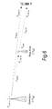
- Figure 8 illustrates the single hop TDD frame structure used in the OFDMA physical layer mode of the IEEE802.16 standard (WiMAX).
- Each frame is divided into DL and UL subframes, each being a discrete transmission interval. They are separated by Transmit/Receive and Receive/Transmit Transition Guard interval (TTG and RTG respectively).
- TTG and RTG Transmit/Receive and Receive/Transmit Transition Guard interval
- Each DL subframe starts with a preamble followed by the Frame Control Header (FCH), the DL-MAP, and the UL-MAP.
- FCH Frame Control Header
- the FCH contains the DL Frame Prefix (DLFP) to specify the burst profile and the length of the DL-MAP.
- DLFP DL Frame Prefix
- the DLFP is a data structure transmitted at the beginning of each frame and contains information regarding the current frame; it is mapped to the FCH.
- Simultaneous DL allocations can be broadcast, multicast and unicast and they can also include an allocation for another BS rather than a serving BS.
- Simultaneous ULs can be data allocations and ranging or bandwidth requests.
- the process of modulation, transmission, reception and demodulation of an information signal will cause typically the original signal to experience some distortion.
- These distortions may include delay, frequency offset and phase rotation and can result in the reception of multiple independently distorted replicas of the original signal.
- these training sequences are known in the receiver, it is possible to estimate the distortion introduced by the transmission process and then correct the received information signal so that the distortion is minimized or completely removed.
- a training signal can be used in both the synchronization (time & frequency) and channel estimation and equalization stages of the receiver.
- Each sequence in the set is distinct from all other sequences such that it is possible at the receiver to distinguish the identity of a transmitter in a communication network where multiple transmitters exist. This allows the receiver to ascertain certain properties possessed by the transmitter as well as estimate the transmitter and channel induced distortion that will be experienced on a signal that is received from that particular transmitter.
- single hop communication systems e.g. IEEE802.16e-2005
- one such transmission signal that can be used for the purposes of identification and training and synchronisation is the preamble sequence. As its name suggests, it is transmitted at the start of every frame prior to the transmission of data.
- a 802.16e-2005 single hop subscriber or mobile station SS or MS
- SS or MS single hop subscriber or mobile station
- a relay station may be required to transmit a preamble to enable the MS or SS to identify, synchronise and communication with it.
- all the preamble transmissions from all of the transmitters should be time synchronized in a cellular style network, such a requirement precludes an active RS from being able to receive the preamble sequence from a BS or another RS due to the physical limitation that it cannot transmit and receive on the same transmission resource at the same time.
- RS When RS are introduced into a synchronous network it is furthermore desirable for there transmissions to be synchronised with those of the existing BS, so that the MS can continue to benefit from the associated advantages of a synchronous network. Therefore, RS must start its transmission at the same time as a BS and they must both transmit there synchronisation signal for the purposes of MS transmitter identification and synchronisation at the same time instant. This then makes it impractical for the RS, once transmitting the synchronisation signal in a single frequency TDD network to receive the BS synchronisation signal simultaneously. Hence there is no reference which the RS can use to maintain synchronisation with the BS whilst operational (i.e. transmitting its own synchronisation and identification signal).
- the inventors have recognised this limitation in the RS, proposing embodiments which involve devising a new signal for transmission by the BS or RS which can be received by the RS to enable it to both transmit a standard preamble sequence and receive the new signal to enable it to perform transmitter identification, synchronisation and channel estimation.
- the solution of invention embodiments to this problem is to transmit a special BS-RS (or RS-RS in the case of more than two-hop) synchronisation signal.
- the signal could also be an RS-MS signal if appropriate.
- the signal should preferably have the properties that it cannot be accidentally detected as a false frame start point by an MS who is not aware of the fact that BS or RS may transmit this "relay midamble".
- Figure 8 illustrates the single hop TDD frame structure used in the OFDMA physical layer mode of the IEEE802.16 standard indicating the location of the standard mandatory preamble sequence that can be used by an MS for BS identification and training of the distortion correcting elements of the receiver.
- Embodiments of the invention introduce a new signal that is transmitted in another region of the DL sub-frame (other than the region where the preamble is located). This signal could be in the middle of the DL sub-frame, thus forming a mid-amble or at the end of the sub-frame, thus forming a post-amble. From here on, for the sake of generality, the new signal is referred to as the relay-amble (RA) or relay midamble (RM).
- RA relay-amble
- RM relay midamble
- the requirements for the RA similar to those of the preamble, are that it can be used by the receiver to identify and distinguish the transmitter from potentially a number of other transmitters in the communication network. It must also enable the receiver to estimate, or update an existing estimate, of the transmitter and channel induced distortion. It must not be accidentally identified by an MS as a normal preamble sequence, as this may confuse a legacy MS that is not aware of the existence of relay-ambles.
- the properties of the transmitted RA signal should therefore be:
- PN pseudo-noise
- Golay sequences [4] [5] Golay sequences [4] [5]
- CAZAC sequences Constant Amplitude & Zero Auto Correlation
- Chu [2] and Frank-Zadoff [1] sequences to construct the relay-amble. All of these sequences are known to exhibit some or all of the required properties and hence have been previously proposed for use in forming such training or identification sequences.
- the BS or RS that is transmitting an RA will first decide on the location of the RA transmission within the downlink sub-frame. As mentioned earlier, the transmission could be located anywhere within the frame. However, it is possible to envisage that certain formal frame structures may be required to support relaying [refer to GB 0616477.6 , GB 0616481.8 and GB 0616479.2 ] that limit the flexibility afforded to the transmitter in placement of the RA.
- the transmitter determines the amount of transmission resource that will be allocated to the RA.
- Various factors will have an effect on this decision including: the effective frequency reuse to be achieved at a multi-sector transmitter; the requirement to reduce interference; the amount of transmission resource that will be utilized by the BS to RS or RS to RS data transmission; the method used for separating different transmitters operating on the same frequency in a cellular network; and also the type of sequence used to form the RA.
- One solution is to form an RA zone in the downlink sub-frame, as shown in Figure 1(a) .
- a whole OFDM symbol is reserved for RA transmission.
- An alternative approach is to allocate a sub-band or region of the downlink sub-frame to the RA transmission, as shown in Figure 1(b) .
- the former is appropriate if the whole band is available for BS to RS or RS to RS data transmission, whilst the latter could be adopted to minimize the amount of transmission resource required if a full symbol is not required as could be the case if the set of RAs is small or the BS to RS or RS to RS data transmission is only utilizing a part of the total frequency transmission resource (i.e. a sub-band).
- the transmitter determines the usage of the transmission resource within the zone or region.
- Numerous usage scenarios can be envisaged, including: all tones are allocated for RA transmission; the total number of tones are decimated so that the RA is allocated to every second, third, fourth, etc, tone; a contiguous sub-band of tones is allocated.
- Each of these mechanisms is illustrated in Figure 2 for the case of an RA zone. It is also possible to extend the proposed methods to the case of an RA region.
- the benefit of the first approach is that it enables accurate channel estimation as each tone is illuminated with a known transmission enabling distortion to be determined on each individual subcarrier.
- the benefit of the second approach is that in a frequency reuse 1 scenario, by decimating the tones and using different offsets of decimated sequences at different transmitters it is possible to achieve an effective frequency reuse of greater than 1.
- An example could be a three sector site, where a decimation factor of three is employed at each sector using an incrementing offset of the starting subcarrier number on each sector (i.e. sector 1 uses subcarriers ⁇ 0, 3, 6, etc ⁇ , sector 2 uses ⁇ 1, 4, 7, etc ⁇ and sector 3 uses ⁇ 2, 5, 8, etc ⁇ .
- the benefit of the third approach is that similar to the case above, it is possible to achieve an effective frequency reuse of greater than 1 by assigning different sub-bands to different sectors.
- the final stage is to generate the training and identification sequence to be transmitted on the identified tones.
- the training and identification sequence As discussed previously, it is possible to make use of a number of different well known sequences for this purpose.
- zone or region allocation will be performed in some network management entity (this could be located within the core network or within one of the transmitters). Also the same situation may exist for the case of allocation of a particular sequence to a transmitter, especially if the sequence is conveying inherent identification parameters. This network management entity will then ensure that the location of the zone or region across all transmitters in the cellular network is harmonized. This then prevents interference between RA transmissions from one transmitter and data transmissions from another, which could be significant especially if the RA transmission power is boosted due to its lower PAPR properties. It will also ensure that the allocation of identification parameters ensures that from a receiver point of view, it will never experience receiving the same identification from two visible transmitters (i.e. there is sufficient spatial separation between the reuse of the same identification sequence).
- the transmitter may include some signalling information in the broadcast message to indicate the existence and location of the RA zone or region to the RS, alternatively it may also include signalling information in a multicast or unicast message specifically directed towards the RS to inform it of the RA existence.
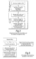
- Figure 3 provides a flowchart that describes the interaction between the network management entity and the basestations which are to transmit an RA.
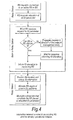
- Figure 4 provides a flowchart that describes the interaction between an RS that has entered into an already operational network and the BS or RS to which it is attempting to associate.
- Figure 5 outlines the RA reception and processing procedure in the receiver.
- RM relay midamble
- the preamble power shall be boosted by 9dB over the average data power.
- the RM power at 3dB below the preamble power.
- An MS or RS then scanning the spectrum for a preamble may see a RM.
- the preamble will always appear with a stronger correlation peak compared to the RM, due to the fact that the preamble/RM pairs from a BS or active RS will experience the same pathloss. Therefore, when deciding on a target, the MS (or RS that is entering the network) will always lock to the preamble transmission rather than the RM transmission.
- the RM position can be controlled dynamically through signalling messages contained in the normal (access-link) transmission period (i.e. BS or RS to MS) or in the dedicated RS (relay link) transmission period.
- the normal (access-link) transmission period i.e. BS or RS to MS
- the dedicated RS (relay link) transmission period i.e. BS or RS to MS
- Embodiments of the present invention may be implemented in hardware, or as software modules running on one or more processors, or on a combination thereof. That is, those skilled in the art will appreciate that a microprocessor or digital signal processor (DSP) may be used in practice to implement some or all of the functionality of a transmitter embodying the present invention.
- DSP digital signal processor
- the invention may also be embodied as one or more device or apparatus programs (e.g. computer programs and computer program products) for carrying out part or all of any of the methods described herein.
- Such programs embodying the present invention may be stored on computer-readable media, or could, for example, be in the form of one or more signals.
- Such signals may be data signals downloadable from an Internet website, or provided on a carrier signal, or in any other form.
- This contribution contains a technical proposal for a relay midamble that can optionally be transmitted by a MR-BS or RS in the R-DL interval.
- This midamble can received by an RS instead of the preamble transmitted in the access link when the RS is transmitting its own preamble.
- the BS and RSs operate in a frame time synchronous manner [1], it is not practical for the RS to receive preamble transmissions in a TDD system due to the fact that they are also required to transmit preambles to support connection of SS as defined in IEEE Std. 802.16.
- the proposal is to define a new relay midamble that can be transmitted by a BS or RS during the R-Link transmission interval for reception by an RS in place of reception of the preamble in the access link interval.
- the midamble is designed to have properties very similar to the normal preamble to minimize the impact on the existing standard and also enable reuse of existing technology defined for MS receiver at the RS receiver.
- the sequence used for the relay midamble is the same as the set of sequences used for the preamble.
- the two differences are that the power of each tone is boosted by +6dB over unboosted data subcarrier power and the location of the RM is flexible [1]. This prevents a simple correlation function at the SS from selecting the RM over the preamble as the candidate point for frame start and downlink channel selection during network entry.
- Table 2 compares the power boosting difference between the various different data and pilot tone modulation types.
- the existence of the RM is controlled by the BS.
- the option for the RS to request transmission of an RM is left FFS.
- two mechanisms are envisaged. The first is static request during network entry through a SBC message indicating RM is required for operation.
- the second is dynamic request through an unsolicited MAC management message from the RS to the BS.
- Table 2 Comparison of data and pilot tone boosting. Modulation Type I Value Q Value Amplitude Boost Amplitude Power (dB) QPSK 0.71 0.71 1.00 1.00 0.00 Premable 1.00 0.00 1.00 2.83 9.03 Ranging 1.00 0.00 1.00 1.00 0.00 Pilot 1.00 0.00 1.00 1.33 2.50 RM 1.00 0.00 1.00 2.00 6.02
- the BS or RS may also transmit the RM in the R-DL transmission interval to facilitate RS synchronization and identification of the BS or RS by other RSs.
- the subcarrier sets and the series used to modulate the RM pilots shall be the same as that defined for the preamble in 8.4.6.1.1.
- the modulation used for the RM pilots is boosted BPSK as defined in 8.4.9.4.3.3.
- RSs be time synchronized to a common timing signal that is also used for BS synchronization, as described in Section 8.4.10.1.1.
- the timing signal shall be a 1 pps timing pulse and a 10MHz frequency reference. These signals are typically provided by a GPS receiver.
- the RS may utilize an RM transmission from a BS or other RS, as described in Section 8.4.6.1.1.3, to maintain synchronization.
- the RS shall continue to operate.
- the RS shall automatically resynchronize to the network timing signal when it becomes available.
- frequency references derived from the timing reference may be used to control the frequency accuracy of RSs provided that they meet the accuracy requirements of 8.4.14. This applies during normal operation and during loss of timing reference.
- both transmitter center frequency and the sampling frequency shall be derived from the same reference oscillator.
- the reference frequency accuracy at the RS shall be better than ⁇ 2ppm and the RS uplink transmission shall be locked to the BS, so that its center frequency shall deviate no more than 2% of the subcarrier spacing compared to the BS center frequency.
- the RS downlink transmission shall be locked to the BS, so that its center frequency shall deviate no more than 2% of the subcarrier spacing compared to the BS center frequency.
Applications Claiming Priority (3)
| Application Number | Priority Date | Filing Date | Title |
|---|---|---|---|
| GB0616474A GB2440981A (en) | 2006-08-18 | 2006-08-18 | Wireless multi-hop communication system |
| GB0622124A GB2443466A (en) | 2006-11-06 | 2006-11-06 | Relay station for multi-hop communication system |
| EP07113554A EP1890447A2 (fr) | 2006-08-18 | 2007-07-31 | Systèmes de communications |
Related Parent Applications (2)
| Application Number | Title | Priority Date | Filing Date |
|---|---|---|---|
| EP07113554A Division EP1890447A2 (fr) | 2006-08-18 | 2007-07-31 | Systèmes de communications |
| EP07113554.5 Division | 2007-07-31 |
Publications (2)
| Publication Number | Publication Date |
|---|---|
| EP2136587A2 true EP2136587A2 (fr) | 2009-12-23 |
| EP2136587A3 EP2136587A3 (fr) | 2012-05-02 |
Family
ID=38800735
Family Applications (2)
| Application Number | Title | Priority Date | Filing Date |
|---|---|---|---|
| EP09171903A Withdrawn EP2136587A3 (fr) | 2006-08-18 | 2007-07-31 | Systèmes de communication |
| EP07113554A Withdrawn EP1890447A2 (fr) | 2006-08-18 | 2007-07-31 | Systèmes de communications |
Family Applications After (1)
| Application Number | Title | Priority Date | Filing Date |
|---|---|---|---|
| EP07113554A Withdrawn EP1890447A2 (fr) | 2006-08-18 | 2007-07-31 | Systèmes de communications |
Country Status (6)
| Country | Link |
|---|---|
| US (2) | US20080043712A1 (fr) |
| EP (2) | EP2136587A3 (fr) |
| JP (2) | JP4985218B2 (fr) |
| KR (2) | KR100937569B1 (fr) |
| CN (1) | CN101820309A (fr) |
| TW (2) | TW200824334A (fr) |
Cited By (1)
| Publication number | Priority date | Publication date | Assignee | Title |
|---|---|---|---|---|
| US11129044B2 (en) * | 2017-12-11 | 2021-09-21 | Wangsu Science & Technology Co., Ltd. | Method for transmitting wireless network data, sending terminal and receiving terminal |
Families Citing this family (23)
| Publication number | Priority date | Publication date | Assignee | Title |
|---|---|---|---|---|
| GB2440981A (en) * | 2006-08-18 | 2008-02-20 | Fujitsu Ltd | Wireless multi-hop communication system |
| TW200824334A (en) * | 2006-08-18 | 2008-06-01 | Fujitsu Ltd | Communication systems |
| US8189455B1 (en) | 2007-11-07 | 2012-05-29 | Research In Motion Limited | Coding information for communication over an orthogonal frequency division multiple access (OFDMA)-based wireless link |
| US8059759B2 (en) | 2008-05-19 | 2011-11-15 | Qualcomm Incorporated | Methods and systems for initial FCH processing |
| CN102089996B (zh) * | 2008-07-10 | 2016-04-20 | 艾利森电话股份有限公司 | 通过中间设备插入信号的方法和设备 |
| WO2010021598A1 (fr) * | 2008-08-18 | 2010-02-25 | Agency For Science, Technology And Research | Techniques de préfixe cyclique |
| EP2175584B1 (fr) * | 2008-10-08 | 2011-08-31 | Fujitsu Limited | Identifiants de station de réseau dans un système de communication sans fil |
| KR101622406B1 (ko) * | 2009-04-24 | 2016-05-19 | 엘지전자 주식회사 | 무선 통신 시스템에서 네트워크 접속 방법 및 장치 |
| CN102461306B (zh) * | 2009-06-12 | 2015-11-25 | 诺基亚公司 | 便于中继节点通信的方法和装置 |
| US8498252B2 (en) * | 2009-07-06 | 2013-07-30 | Intel Corporation | Midamble for wireless networks |
| KR101618782B1 (ko) * | 2009-08-24 | 2016-05-12 | 엘지전자 주식회사 | 광대역 무선 접속 시스템에서 중계국의 기지국 시스템 정보 갱신 방법 |
| JP4990386B2 (ja) * | 2010-07-08 | 2012-08-01 | 株式会社エヌ・ティ・ティ・ドコモ | 移動通信方法、無線基地局及びリレーノード |
| CN101951645B (zh) * | 2010-09-03 | 2012-12-19 | 北京航空航天大学 | 一种蜂窝中继网络中的下行自适应传输方法 |
| KR101781356B1 (ko) * | 2011-01-28 | 2017-09-25 | 삼성전자주식회사 | 무선통신 시스템에서 고립된 단말을 지원하는 방법 및 장치 |
| JP5869359B2 (ja) * | 2012-02-09 | 2016-02-24 | 株式会社日立国際電気 | 無線通信システム及び無線通信方法 |
| GB2509088A (en) * | 2012-12-19 | 2014-06-25 | Broadcom Corp | A reference sequence for synchronisation and channel estimation in local area communication scenarios |
| US9008203B2 (en) | 2013-03-13 | 2015-04-14 | Sony Corporation | Transmitters, receivers and methods of transmitting and receiving |
| US20140328168A1 (en) * | 2013-05-06 | 2014-11-06 | Minyoung Park | Apparatus, system and method of adjusting transmission intervals for discovery frames |
| CN105284068B (zh) * | 2013-06-05 | 2019-08-27 | 索尼公司 | 用于传输有效载荷数据和紧急信息的传输器和传输方法 |
| TWI651009B (zh) * | 2014-02-26 | 2019-02-11 | 日商新力股份有限公司 | 送訊裝置、收訊裝置及資訊處理方法 |
| GB2547266A (en) * | 2016-02-12 | 2017-08-16 | Sony Corp | Transmitter, receiver and methods |
| GB2547267A (en) * | 2016-02-12 | 2017-08-16 | Sony Corp | Transmitter, receiver and methods |
| JP7051872B2 (ja) * | 2017-08-18 | 2022-04-11 | 株式会社Nttドコモ | 端末、基地局及び無線通信システム |
Citations (3)
| Publication number | Priority date | Publication date | Assignee | Title |
|---|---|---|---|---|
| GB616481A (en) | 1946-09-05 | 1949-01-21 | Donald Mccombie Grassick | Improvements in or relating to ignition systems for gas turbines |
| GB616477A (en) | 1946-04-19 | 1949-01-21 | Mathieson Alkali Works | Improvements in the processing of wool |
| GB616479A (en) | 1945-09-05 | 1949-01-21 | Glenn Varley S | Mounting for doors swinging upwardly into horizontal position when open |
Family Cites Families (44)
| Publication number | Priority date | Publication date | Assignee | Title |
|---|---|---|---|---|
| DE3403715A1 (de) * | 1984-02-03 | 1985-08-08 | Licentia Patent-Verwaltungs-Gmbh, 6000 Frankfurt | Digitales zellenfunksystem mit zeitmultiplex |
| FR2608874B1 (fr) * | 1986-12-19 | 1989-03-24 | Trt Telecom Radio Electr | Procede de reglage du retard entre stations dans un systeme de transmission d'informations comprenant un grand nombre de stations relais en cascade et utilisant dans un sens de transmission le principe dit d'a.m.r.t. et systeme pour lequel est mis en oeuvre un tel procede |
| JP3081076B2 (ja) * | 1993-03-10 | 2000-08-28 | 松下電器産業株式会社 | 無線通信装置におけるアンテナ・ダイバーシチ方法 |
| US5719868A (en) * | 1995-10-05 | 1998-02-17 | Rockwell International | Dynamic distributed, multi-channel time division multiple access slot assignment method for a network of nodes |
| US6370384B1 (en) * | 1998-07-30 | 2002-04-09 | Airnet Communications Corporation | Frequency re-use planning for wireless communications system using wireless translating repeaters |
| US7006530B2 (en) * | 2000-12-22 | 2006-02-28 | Wi-Lan, Inc. | Method and system for adaptively obtaining bandwidth allocation requests |
| US7158784B1 (en) | 2000-03-31 | 2007-01-02 | Aperto Networks, Inc. | Robust topology wireless communication using broadband access points |
| US6950413B1 (en) * | 2000-07-20 | 2005-09-27 | Jenn-Chorng Liou | Mutually-assisted proximity informer system and method with wireless devices |
| US6701129B1 (en) * | 2000-09-27 | 2004-03-02 | Nortel Networks Limited | Receiver based adaptive modulation scheme |
| US7512109B2 (en) * | 2000-09-29 | 2009-03-31 | Intel Corporation | Slot structure for radio communications system |
| EP1288674B1 (fr) * | 2001-09-03 | 2006-02-15 | STMicroelectronics N.V. | Procédé et dispositif d'estimation de la vitesse de déplacement d'un terminal mobile d'un système de communication sans fil |
| US7096274B1 (en) * | 2002-02-12 | 2006-08-22 | 3Com Corporation | Optimum frame size predictor for wireless Local Area Network |
| JP2004040568A (ja) * | 2002-07-04 | 2004-02-05 | Denso Corp | 無線通信端末 |
| DE10241959A1 (de) * | 2002-09-10 | 2004-03-11 | Siemens Ag | Verfahren zur Signalübertragung in einem Funk-Kommunikationssystem |
| US7580394B2 (en) * | 2002-11-27 | 2009-08-25 | Nokia Corporation | System and method for collision-free transmission scheduling in a network |
| US20040109428A1 (en) * | 2002-12-09 | 2004-06-10 | Srikanth Krishnamurthy | Method and apparatus for resource allocation for multiple traffic classes in wireless ad-hoc networks |
| US7508798B2 (en) * | 2002-12-16 | 2009-03-24 | Nortel Networks Limited | Virtual mimo communication system |
| KR101008978B1 (ko) * | 2003-03-04 | 2011-01-17 | 삼성전자주식회사 | 애드 혹 네트워크 환경에서 신뢰성 있게 브로드캐스팅하는시스템 및 방법 |
| IL156540A0 (en) * | 2003-06-19 | 2004-01-04 | Zion Hada | Ofdma communication system and method |
| US7903538B2 (en) * | 2003-08-06 | 2011-03-08 | Intel Corporation | Technique to select transmission parameters |
| US7400856B2 (en) * | 2003-09-03 | 2008-07-15 | Motorola, Inc. | Method and apparatus for relay facilitated communications |
| KR100533686B1 (ko) * | 2004-05-21 | 2005-12-05 | 삼성전자주식회사 | 모바일 애드 혹 네트워크에서의 데이터 전송 방법 및 이를이용한 네트워크 장치 |
| US7864659B2 (en) * | 2004-08-02 | 2011-01-04 | Interdigital Technology Corporation | Quality control scheme for multiple-input multiple-output (MIMO) orthogonal frequency division multiplexing (OFDM) systems |
| US7496113B2 (en) * | 2004-08-16 | 2009-02-24 | Zte (Usa) Inc. | Fast cell search and accurate synchronization in wireless communications |
| JP4494134B2 (ja) * | 2004-09-01 | 2010-06-30 | Kddi株式会社 | 無線通信システム、中継局装置および基地局装置 |
| WO2006075870A1 (fr) * | 2005-01-11 | 2006-07-20 | Samsung Electronics Co., Ltd. | Procede et systeme pour indiquer une repartition de rafales de donnees dans un systeme de radiocommunications |
| US20060215542A1 (en) * | 2005-03-25 | 2006-09-28 | Mandyam Giridhar D | Method and apparatus for providing single-sideband orthogonal frequency division multiplexing (OFDM) transmission |
| US7486928B2 (en) * | 2005-04-14 | 2009-02-03 | Kddi Corporation | Methods and apparatus for wireless communications |
| US20080198790A1 (en) * | 2005-05-12 | 2008-08-21 | Ofer Harpak | Device and Method for Exchanging Information Over Terrestrial and Satellite Links |
| JP2006319676A (ja) * | 2005-05-12 | 2006-11-24 | Oki Electric Ind Co Ltd | フレーム送信方法、トポロジー取得方法、及び無線通信システム |
| KR100839966B1 (ko) * | 2005-06-29 | 2008-06-20 | 삼성전자주식회사 | 통신 시스템에서 링크의 상태 보고 방법 및 시스템 |
| US7466964B2 (en) * | 2005-06-29 | 2008-12-16 | Intel Corporation | Wireless communication device and method for coordinated channel access with reduced latency in a wireless network |
| KR20070013444A (ko) * | 2005-07-26 | 2007-01-31 | 삼성전자주식회사 | 무선통신시스템에서 이종망간 핸드오프 처리 장치 및 방법 |
| US7599341B2 (en) * | 2006-02-28 | 2009-10-06 | Motorola, Inc. | System and method for managing communication routing within a wireless multi-hop network |
| US20070217353A1 (en) * | 2006-03-20 | 2007-09-20 | Motorola, Inc. | Method and Apparatus for Transmitting Data Within a Multi-Hop Communication System |
| GB2440980A (en) * | 2006-08-18 | 2008-02-20 | Fujitsu Ltd | Wireless multi-hop communication system |
| GB2440985A (en) * | 2006-08-18 | 2008-02-20 | Fujitsu Ltd | Wireless multi-hop communication system |
| GB2440981A (en) * | 2006-08-18 | 2008-02-20 | Fujitsu Ltd | Wireless multi-hop communication system |
| GB2440982A (en) * | 2006-08-18 | 2008-02-20 | Fujitsu Ltd | Wireless multi-hop communication system |
| GB0616472D0 (en) * | 2006-08-18 | 2006-09-27 | Fujitsu Ltd | Communication systems |
| GB2440984A (en) * | 2006-08-18 | 2008-02-20 | Fujitsu Ltd | Wireless multi-hop communication system |
| TW200824334A (en) * | 2006-08-18 | 2008-06-01 | Fujitsu Ltd | Communication systems |
| GB0616476D0 (en) * | 2006-08-18 | 2006-09-27 | Fujitsu Ltd | Communication systems |
| GB2440986A (en) * | 2006-08-18 | 2008-02-20 | Fujitsu Ltd | Wireless multi-hop communication system |
-
2007
- 2007-07-31 TW TW096127971A patent/TW200824334A/zh unknown
- 2007-07-31 EP EP09171903A patent/EP2136587A3/fr not_active Withdrawn
- 2007-07-31 TW TW099100661A patent/TW201028024A/zh unknown
- 2007-07-31 EP EP07113554A patent/EP1890447A2/fr not_active Withdrawn
- 2007-08-17 CN CN200910265272A patent/CN101820309A/zh active Pending
- 2007-08-17 US US11/840,669 patent/US20080043712A1/en not_active Abandoned
- 2007-08-17 KR KR1020070083046A patent/KR100937569B1/ko not_active IP Right Cessation
- 2007-08-20 JP JP2007214178A patent/JP4985218B2/ja not_active Expired - Fee Related
-
2009
- 2009-09-28 KR KR1020090091936A patent/KR100988663B1/ko not_active IP Right Cessation
- 2009-10-26 JP JP2009245631A patent/JP2010063125A/ja active Pending
- 2009-12-29 US US12/649,096 patent/US20100142436A1/en not_active Abandoned
Patent Citations (3)
| Publication number | Priority date | Publication date | Assignee | Title |
|---|---|---|---|---|
| GB616479A (en) | 1945-09-05 | 1949-01-21 | Glenn Varley S | Mounting for doors swinging upwardly into horizontal position when open |
| GB616477A (en) | 1946-04-19 | 1949-01-21 | Mathieson Alkali Works | Improvements in the processing of wool |
| GB616481A (en) | 1946-09-05 | 1949-01-21 | Donald Mccombie Grassick | Improvements in or relating to ignition systems for gas turbines |
Non-Patent Citations (6)
| Title |
|---|
| CHU DC: "Polyphase codes with good periodic correlation properties", IEEE TRANSACTIONS ON INFORMATION THEORY, July 1972 (1972-07-01), pages 531 - 2 |
| FRANK RL; ZADOFF SA: "Phase shift codes with good periodic correlation properties", IEEE TRANSACTIONS ON INFORMATION THEORY, October 1962 (1962-10-01), pages 381 - 2 |
| HART, M ET AL.: "Frame structure for multihop relaying support", IEEE C802.16J-06/138, IEEE 802.16 MEETING #46, November 2006 (2006-11-01) |
| M.J.E. GOLAY: "Complementary series", IRE TRANS. INFORM. THEORY, April 1961 (1961-04-01), pages 82 - 87 |
| M.J.E. GOLAY: "Multislit spectroscopy", J. OPT. SOC. AMER., vol. 39, 1949, pages 437 - 444 |
| MILEWSKI A.: "Periodic sequences with optimal properties for channel estimation and fast start-up equalization", IBM RESEARCH AND DEVELOPMENT JOURNAL, September 1983 (1983-09-01), pages 426 - 31 |
Cited By (1)
| Publication number | Priority date | Publication date | Assignee | Title |
|---|---|---|---|---|
| US11129044B2 (en) * | 2017-12-11 | 2021-09-21 | Wangsu Science & Technology Co., Ltd. | Method for transmitting wireless network data, sending terminal and receiving terminal |
Also Published As
| Publication number | Publication date |
|---|---|
| TW200824334A (en) | 2008-06-01 |
| EP1890447A2 (fr) | 2008-02-20 |
| KR100988663B1 (ko) | 2010-10-18 |
| EP2136587A3 (fr) | 2012-05-02 |
| KR100937569B1 (ko) | 2010-01-19 |
| US20080043712A1 (en) | 2008-02-21 |
| CN101820309A (zh) | 2010-09-01 |
| KR20090116675A (ko) | 2009-11-11 |
| JP4985218B2 (ja) | 2012-07-25 |
| KR20080016509A (ko) | 2008-02-21 |
| JP2010063125A (ja) | 2010-03-18 |
| US20100142436A1 (en) | 2010-06-10 |
| JP2008048425A (ja) | 2008-02-28 |
| TW201028024A (en) | 2010-07-16 |
Similar Documents
| Publication | Publication Date | Title |
|---|---|---|
| EP2136587A2 (fr) | Systèmes de communication | |
| US9491737B2 (en) | Communication systems | |
| EP1919100B1 (fr) | Systèmes de communication | |
| US7957257B2 (en) | Communication systems | |
| KR101059304B1 (ko) | 통신 시스템들 | |
| EP2178325B1 (fr) | Communication sans fils à sauts multiples | |
| EP2146463A2 (fr) | Système et procédé de communication sans fils à bonds multiples | |
| GB2443466A (en) | Relay station for multi-hop communication system | |
| KR101110932B1 (ko) | 통신 시스템들 | |
| KR100983942B1 (ko) | 멀티-홉 무선 통신 시스템에서 이용하기 위한 통신 방법, 멀티-홉 무선 통신 시스템, 기지국 장치, 중간 장치, 및 사용자 장비 |
Legal Events
| Date | Code | Title | Description |
|---|---|---|---|
| PUAI | Public reference made under article 153(3) epc to a published international application that has entered the european phase |
Free format text: ORIGINAL CODE: 0009012 |
|
| AC | Divisional application: reference to earlier application |
Ref document number: 1890447 Country of ref document: EP Kind code of ref document: P |
|
| AK | Designated contracting states |
Kind code of ref document: A2 Designated state(s): DE FR GB |
|
| PUAL | Search report despatched |
Free format text: ORIGINAL CODE: 0009013 |
|
| AK | Designated contracting states |
Kind code of ref document: A3 Designated state(s): DE FR GB |
|
| AX | Request for extension of the european patent |
Extension state: AL BA HR MK RS |
|
| RIC1 | Information provided on ipc code assigned before grant |
Ipc: H04W 40/22 20090101ALI20120327BHEP Ipc: H04B 7/15 20060101ALI20120327BHEP Ipc: H04W 28/16 20090101AFI20120327BHEP |
|
| STAA | Information on the status of an ep patent application or granted ep patent |
Free format text: STATUS: THE APPLICATION HAS BEEN WITHDRAWN |
|
| 18W | Application withdrawn |
Effective date: 20120515 |