EP2135222B1 - Automatic generation of building instructions for building element models - Google Patents
Automatic generation of building instructions for building element models Download PDFInfo
- Publication number
- EP2135222B1 EP2135222B1 EP08717863A EP08717863A EP2135222B1 EP 2135222 B1 EP2135222 B1 EP 2135222B1 EP 08717863 A EP08717863 A EP 08717863A EP 08717863 A EP08717863 A EP 08717863A EP 2135222 B1 EP2135222 B1 EP 2135222B1
- Authority
- EP
- European Patent Office
- Prior art keywords
- building
- model
- building element
- sub
- elements
- Prior art date
- Legal status (The legal status is an assumption and is not a legal conclusion. Google has not performed a legal analysis and makes no representation as to the accuracy of the status listed.)
- Active
Links
Images



Classifications
-
- G—PHYSICS
- G06—COMPUTING OR CALCULATING; COUNTING
- G06T—IMAGE DATA PROCESSING OR GENERATION, IN GENERAL
- G06T17/00—Three-dimensional [3D] modelling for computer graphics
- G06T17/10—Constructive solid geometry [CSG] using solid primitives, e.g. cylinders, cubes
-
- G—PHYSICS
- G06—COMPUTING OR CALCULATING; COUNTING
- G06T—IMAGE DATA PROCESSING OR GENERATION, IN GENERAL
- G06T19/00—Manipulating three-dimensional [3D] models or images for computer graphics
- G06T19/20—Editing of three-dimensional [3D] images, e.g. changing shapes or colours, aligning objects or positioning parts
-
- G—PHYSICS
- G06—COMPUTING OR CALCULATING; COUNTING
- G06T—IMAGE DATA PROCESSING OR GENERATION, IN GENERAL
- G06T2219/00—Indexing scheme for manipulating 3D models or images for computer graphics
- G06T2219/20—Indexing scheme for editing of 3D models
- G06T2219/2008—Assembling, disassembling
Definitions
- the present invention relates to the generation of building instructions for building element models.
- modelling concepts of physical construction toy sets There are various known types of modelling concepts of physical construction toy sets. Especially modular or semi-modular concepts are very popular as they provide an interesting and challenging play experience. Typically, these concepts provide a set of pre-manufactured building elements that can be interconnected with each other in some predetermined way by means of connection elements of the pre-manufactured elements.
- the pre-manufactured building elements resemble well-known objects adapted to a specific modelling task. Thus in e.g. building a model of a house the building elements may resemble wall bricks, roof tiles, doors, and windows.
- the object of selecting the building elements in this way is that the work involved with the building of a model of a house is reduced significantly compared to a situation where all details of the house are to be defined each time a new model should be made. However, the complete freedom in building a house or another object is traded off for the simplicity of building the model.
- the toy construction sets available under the name LEGO comprise a plurality of different types of interconnectable building elements having protrusions and corresponding cavities as connecting elements.
- the connecting elements are arranged according to regular grid patterns, thereby allowing a wide variety of interconnections between building elements.
- such toy construction sets comprise a set of building elements suitable for creating one or more building element models, e.g. an animal, a robot, or another creature, a car, an airplane, a spaceship, a building, or the like.
- a construction set further includes printed building instructions or assembly instructions that illustrate how to construct a certain model from the building elements of the set. Nevertheless, it is an interesting feature of such construction sets that they inspire children to create their own models.
- the building instructions enclosed in a toy construction set comprise a sequence of pictures illustrating step by step how and in which order to add the building elements to the model.
- Such building instructions have the advantage that they are easy to follow, even for children without great experience in toy construction sets and/or without reading skills.
- a building instruction for a model may be regarded as a sequence of construction steps and substeps in which building elements are assembled. The sequence starts with one or more initial building elements and develops over a series of steps into the full assembly which is a construction of the model. In each step either a single building element or a sub-assembly of building elements is added.
- the term sub-assembly refers to a subset of interconnected building elements of the building element model. Adding a sub-assembly rather than a building element may thus involve a subordinate building instruction for that sub-assembly to be added to the main building instruction.
- a subordinate building instruction will also be called a substep.
- the sequence of steps may generally be represented as a branched tree of steps where each branch contains subordinate building instructions.
- building instructions have been generated manually, e.g. by manually determining reasonable building steps, drawing the corresponding instructions in a CAD system, and finally printing the thus generated instructions.
- building instructions are of high-quality, i.e. are easy to follow, the above production processes have the disadvantage that they require great skill and are labour-intensive.
- building instructions typically only exist for building element models designed by the manufacturer of the building elements.
- the above prior art methods for generating building instructions are not suitable for children who wish to produce building instructions for their own models, which would allow them to share their models with their friends.
- building instructions have been generated in electronic rather than in printed form.
- animated building instructions where the more complicated building steps are animated.
- the production of such building instructions still involves a design and a drawing/animation of the building steps by skilled designers.
- the system calculates a sequence of assembly steps based on an extensive search algorithm taking the given constraints into consideration. It is a problem of the above prior art system that it is computationally expensive and requires complicated input data, thus requiring a high degree of abstract thinking from the user.
- the present invention relates to a computer-implemented method of generation of building instructions according to claims 1 and 19, a data processing system according to claim 21, a computer data product according to claim 22 and a computer data signal according to claim 23.
- a sequence of construction steps may be efficiently determined by determining one or more sequences of deconstruction steps.
- a building deconstruction for a model may be regarded as a sequence/iterative process of steps and substeps in which building elements are disassembled.
- the sequence starts with the full model and proceeds over a series of steps.
- the process continues until all building elements have been disconnected from the model, while in a partial deconstruction, the process terminates when only a predetermined residual part-model remains.
- a single building element or a sub-assembly of building elements is disconnected.
- Disconnecting a sub-assembly rather than a building element thus may involve a subordinate building deconstruction for that sub-assembly to be associated with the main building deconstruction.
- Such subordinate building deconstruction will also be called a sub-step.
- the sequence of steps of the deconstruction process is generally a branched tree of steps where each branch contains subordinate building deconstructions.
- this information may be used in the process of generating a construction sequence.
- construction steps may be determined responsive to a step of determining a deconstruction sequence. Furthermore, it has turned out that searching for a deconstruction sequence that fulfils certain selection criteria is possible with reasonable computational resources and results in high-quality building instructions.
- the building instructions are easy for a user to generate without requiring the user to posses design skills or abstract knowledge about geometry, constraints, etc.
- the generation of the building instructions is independent of the order in which the user actually has constructed the virtual model. This may be advantageous, since a virtual construction environment may allow the performance of construction steps in an order that may be difficult or even impossible to perform with a physical, real-world model.
- a building deconstruction can be found, it can be reversed, yielding a building instruction, just as it is possible to deconstruct a model by going through a building instruction backwards.
- a sequence of construction steps may be efficiently determined by determining one or more sequences of deconstruction steps and then reversing the order of deconstruction steps to obtain a sequence of construction steps. It is an advantage that this process only requires generation of a single deconstruction sequence.
- each construction step is determined such that the resulting part-model can be obtained by a partial deconstruction of the complete model. Consequently, an efficient process for generating building instructions is provided by a construction process where a deconstruction from the full model down to the current construction stage is simulated at each construction step.
- This embodiment works by construction (starting from an empty set of bricks, ending with the full model) rather than entirely being based on a deconstruction. Since this is a more intuitive way for a user to consider building instructions, it allows for more easy-to-use and powerful ways of allowing users to interact with the process of generating building instructions. An example of a user interaction could be to make objections to any suggested brick, and getting an alternative suggestion. This simple interaction in fact allows users to generate particularly high-quality building instructions in a very short time and a minimal need for user interaction. Furthermore, the generator can ensure that hard constraints are never violated, and consequently no mater what the user objects to, only reasonable suggestions are made.
- the step of determining a subsequent construction step may include receiving a user input, e.g. in the form of at least one of a suggestion, approval, and a rejection of a construction step.
- the step of determining whether the building element model is deconstructable by a sequence of deconstruction steps for deconstructing the building element model resulting in the second part-model may include the step of determining whether the building element model is so deconstructable by a sequence of deconstruction steps, wherein each deconstruction step is selected by one or more predetermined set of selection criteria.
- determining the sequential order of deconstruction steps comprises performing an iterative process, wherein an iteration of the iterative process comprises:
- the process starts with the complete model and generates a sequence of part-models by removing, in each iteration, one or more building elements.
- a search for high quality building instructions generally requires backtracking, and thus is computationally very expensive and even prohibitively expensive for large models, it has turned out that building deconstruction can be achieved by a one-pass algorithm which is much less demanding on the computational hardware.
- LEGO in a complex building system, such as the toy building system marketed under the name LEGO, it may not be possible for some models to be deconstructed building element by building element, because some building elements may lock each other in such a way that no single building element can be disconnected. However, generally all models can be disconnected by removing, in each step, either a single building element or a sub-assembly of building elements.
- determining at least one building element includes:
- sub-assemblies are treated as pseudo-building elements for the purpose of the deconstruction sequence.
- the number of possible sub-assemblies of a building element model generally grows exponentially with the number of building elements in the model. Consequently, even for moderate sized models a top-down approach for searching though all possible sub-assemblies and selecting, given certain criteria, one sub-assembly to be disconnected is computationally prohibitively expensive, even though such an approach may well be feasible when exclusively considering removal of single building elements.
- the method described herein combines the above top-down approach with a bottom-up approach for generating candidate sub-assemblies to be subjected to the top-down search.
- the generation of candidate sub-assembly may be performed according to a set of one or more generator sub-processes or a second set of selection criteria, thus resulting in a subset of candidate sub-assemblies of the set of all possible sub-assemblies of the model.
- the bottom-up approach is used to prune the search space prior to performing the computationally expensive top-down approach.
- top-down search and bottom-up generation result in a process that is computationally less expensive, programmatically easier, and easily extendible, e.g. by adding additional generator sub-processes for generating candidate sub-assemblies.
- the above approach provides an improved control, since it provides a mechanism for controlling the number of candidate sub-assembly to generate, thus providing a mechanism for trading off computational cost against quality of the resulting building instructions and for adjusting the size of the pool of candidates to any given hardware and time requirements.
- At least one of the second set of selection criteria includes determining a connection strength of the connection of one or more of the candidate sub-assemblies with the previous part-model. Consequently, sub-assemblies are generated/selected according to the strength of their connection to the remainder of the previous part-model. It has turned out that this selection/generation strategy for sub-assemblies results in particularly high-quality building instructions.
- Additional or alternative selection rules for efficiently selecting candidate sub-assemblies comprise determining changes in the building direction and/or sub-assemblies that are movably connected to the previous part-model, e.g. by means of a hinge or joint connection, a slider, etc.
- the method comprises representing the previous part-model by a data structure indicative of a graph, e.g. an undirected graph, including nodes indicative of respective building elements of the previous part-model and edges connecting respective nodes indicative of connections between corresponding building elements.
- a data structure indicative of a graph e.g. an undirected graph
- graph partitioning techniques and other techniques known from graph theory see e.g. " Graph Theory and Its Applications” by Jonathan L. Gross and Jay Yellen, Chapman & Hall/CRC, second edition, 2006 ) may be used to efficiently identify suitable candidate sub-assemblies, e.g.
- a model of interconnected building elements corresponds to a connected graph
- a sub-assembly corresponds to a connected subgraph
- the nodes and/or edges of the graph may have one or more respective attributes associated to them corresponding to attributes of the corresponding building elements and connections, respectively.
- nodes of the graph may have one or more of the following attributes attached to them: building element type, building element volume, building element shape/geometry, volume building element mass, a bounding box of the building element, a position of the building element in a coordinate system, a main building direction associated with the building element, the positions, types, and/or directions of connection elements of the building element, and/or the like.
- edges of the graph may have one or more of the following attributes associated with them: connection type, connection strength, direction of connection, and/or the like.
- each building element comprises one or more connection elements adapted to engage with one or more corresponding connection elements of another building element to provide a connection between the building element and the another building element.
- connection elements may impose further restrictions on possible placements of building elements, as a connection is only possible between compatible connection elements, e.g. protrusions that fit into corresponding cavities, when placed in a correct position relative to each other.
- Each connection element may have associated with it a connection element class, each connection element class having associated with it a connection strength.
- the method comprises determining said associated connection strength value of an edge corresponding to a connection between two building elements from at least the number and respective classes of connection elements contributing to the corresponding connection. Consequently, an efficient and accurate method for calculating/estimating connection strengths in a building element model is provided.
- determining said associated connection strength value comprises determining the connection strength from at least the number and respective classes of connection elements contributing to the corresponding connection and from a volume of the two building elements, thereby not only taking the connection strength but also the size of the building elements into account, and thus whether the building elements are easy to hold and manipulate during the building process.
- determining at least one building element to disconnect from the previous part-model resulting in a new part-model comprises computing one or more weight functions for at least one of a subset of the building elements and a set of candidate sub-assemblies of building elements; and selecting one of a single building element and a sub-assembly based on a comparison of the computed weight functions. Consequently, a scalable, extendable, and flexible framework for the selection process is provided, which may be modified or extended by alternative or additional weight functions, and where different selection criteria may be weighted relatively to each other according to their importance/priority.
- the weight functions may include any suitable function of one or more properties of one or more building elements.
- At least one of the one or more weight functions has a range of possible results including a first sub-range indicative of a degree of adequateness to be disconnected and a second subrange indicative of a degree of inadequateness to be disconnected, thereby allowing both to assign positive and negative weights to building elements and/or sub-assemblies.
- selecting a single building element or sub-assembly based on a comparison of the computed weight functions includes computing a total weight from the one or more computed weight functions; wherein computing the total weight includes assigning a value in the second range to the total weight, if at least one of the computed weight functions has a result in the second range, thereby providing a veto-strategy preventing building elements and/or sub-assemblies from being disconnected that do not fulfil certain criteria, even though they may obtain a high weight from other weight functions.
- weight functions that have been found to result in high-quality building instructions include a weight function determining whether a building element or sub-assembly is physically detachable or whether the direction of disconnection of said building element or sub-assembly is e.g. blocked by other parts of the model. For example, such a weight function may be efficiently calculated by computing a stretched geometry of the building element or sub-assembly.
- weight functions includes a weight function assigning a lower weight to articulation building elements and/or building elements that are comprised in an articulation pair of building elements or sub-assemblies, so as to avoid splitting up the model into disjoint/disconnected part-models.
- weight functions include a weight function that decreases with the number of other building elements the building element or sub-assembly is - directly or via other building elements - connected to, it is assured that small, disjoint parts are quickly removed from the model, if they occur.
- one of the weight functions is a function of a connection strength of connections between building elements of a sub-assembly
- building elements and sub-assemblies that are easily disconnectable from the remaining model may be favoured.
- a weight function that assigns a higher weight to building elements and sub-assemblies having a stronger internal connectivity and a weaker external connectivity, result in high-quality building instructions.
- the connectivity strength may be calculated as a strength relative to the volume of the interconnected building elements or sub-assemblies.
- weight functions include weight functions that are functions of at least a property of the building element or sub-assembly and a property of a building element or sub-assembly disconnected during a previous iteration of the iterative process, thus allowing to favour removal of symmetrically positioned building elements or sub-assemblies, building elements or sub-assemblies that are located in a proximity from another, and/or the like.
- properties include the position of building elements relative to a coordinate system, a building element type, and/or the like.
- a weight function may further be a function of a property of more than one building element removed in previous iterations. For example, one or more of the earlier iterations could be assigned with different weights when comparing part-models; for example could the most recent iteration be assigned with a higher weight than the earlier iterations.
- Embodiments of the method described herein receive a digital representation of the building element model.
- a digital representation may be provided by any suitable process, e.g. a computer-implemented construction environment and/or a process for generating a digital representation of a building element model from e.g. one or more images, such as images of a physical model or another object.
- a digital representation of a building element model of an item is created from a CAD model or a set of two-dimensional images of a three-dimensional item.
- Some embodiments of digital representations may include information indicative of the types, position, and/or interconnection of building elements, etc. in any suitable data format.
- Embodiments of digital representations may further include information about global model attributes, attributes of individual building elements, such as a building element type, color, size, bounding box, etc.
- a computer-implemented construction environment for interactively constructing a virtual building element model may comprise a computer program that, when executed on a computer, provides a graphical user interface allowing a user to manipulate virtual building element models, including operations like selecting building elements, adding building elements to the model, deleting building elements from the model, changing the orientation of a building element, changing properties of a building element, e.g. color, type, size, and/or the like, viewing a model, saving a digital representation of a model, loading a digital representation of a previously saved model, etc.
- the virtual building elements may be virtual counterparts of corresponding physical building elements, i.e. have corresponding relative size, shape, color, etc.
- a computer-implemented construction environment may be configured to enforce a predetermined set of restrictions imposed on the relative positions of building elements with respect to each other, such as collision detection between building elements.
- the restrictions correspond to the corresponding restrictions applicable to the corresponding physical building elements, thereby ensuring that a virtual building element model actually can be constructed from the corresponding physical building elements as well.
- building instructions are generated as a sequence of graphical representations such as images.
- Each graphical representation may include a graphical rendering of a partial building element model also referred to as a part-model, thereby providing easy-to-follow building instructions where each graphical representation corresponds to a step in the building process where a predetermined number of building elements are added to the model.
- all part-models or only a subset of the part-models making up the determined construction sequence may be included in the final building instructions, as one or more steps of the construction sequence may be combined into a single image of the building instructions.
- a user can easily determine which building elements are to be added in each step and how they are to be added by comparing two consecutive graphical representations.
- the digital representation of the building element model may be conveniently viewed on a computer.
- building instructions may conveniently be communicated from one computer to another, e.g. stored on a storage medium, sent via a communications network, e.g. as an e-mail attachment, uploaded on a web server, or the like.
- a recipient of the digital representation may thus view the graphical representation and manipulate it, e.g. change a viewing angle, zoom, change viewing options, and/or the like. Consequently, users may easily communicate their building instructions to friends.
- the digital representation does not need to include a graphical rendering of each step of the instructions, thereby keeping the file size of the digital representation small. Furthermore, since the digital representation may comprise all relevant model information, the recipient of a model may even modify the model before generating the building instructions.
- the building instructions may be generated in a predetermined file format, thereby allowing the generation of printed and/or electronic building instructions.
- suitable file formats include HTML, XML, BMP, TIFF, etc.
- the predetermined number of additional building elements added in a step of the step-wise instructions is user-selectable, thereby allowing a user to select between very detailed step by step instructions, wherein e.g. each step corresponds to the placement of a single new building element, and very compact instructions where each step corresponds to a larger number of newly placed building elements.
- the number of building elements added in each step is the same in all steps.
- the number of additional building elements added may be different for different steps of the building instructions.
- the step-size may be controlled by a user for each step, thereby allowing the generation of more fine-grained instructions for more complicated parts of the construction.
- the present invention can be implemented in different ways including the method described above and in the following, a data processing system, and further product means, each yielding one or more of the benefits and advantages described in connection with the first-mentioned method, and each having one or more preferred embodiments corresponding to the preferred embodiments described in connection with the first-mentioned method and disclosed in the dependent claims related thereto.
- the features of the method described above and in the following may be implemented in software and carried out on a data processing system or other processing means caused by the execution of computer-executable instructions.
- the instructions may be program code means loaded in a memory, such as a RAM, from a storage medium or from another computer via a computer network.
- the described features may be implemented by hardwired circuitry instead of software or in combination with software.
- the invention further relates to a data processing system adapted to perform the method described above and in the following.
- the invention further relates to a computer program comprising program code means for performing all the steps of the method described above and in the following when said program is run on a computer.
- the invention further relates to a computer program product comprising program code means for performing the method described above and in the following when said computer program product is run on a computer.
- the program code means may be stored on a computer readable medium and/or embodied as a propagated data signal.
- the computer program comprises a first software component for generating a digital representation of the building element model; and a second software component for generating building instructions from the generated digital representation, thereby providing a separate software component for reading the digital representation of a model and presenting the corresponding building instructions. Consequently, when communicating the building instructions a user may communicate the digital representation together with the second software component, thereby providing a compact, self-contained representation of the building instructions that can be viewed by the recipient without the need for additional software. It will be appreciated, however, that both processes, i.e. the generation of a digital representation of a model and the generation of the building instructions may be integrated in a single software component.
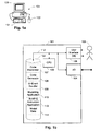
- Figs. 1a-b show a data processing system for generating and manipulating computer-readable models of geometrical objects.
- Fig. 1a shows a schematic view of an example of a computer system.
- the computer system comprises a suitably programmed computer 101, e.g. a personal computer, comprising a display 120, a keyboard 121 and a computer mouse 122 and/or another pointing device, such as a touch pad, a track ball, a light pen, a touch screen, or the like.
- a suitably programmed computer 101 e.g. a personal computer, comprising a display 120, a keyboard 121 and a computer mouse 122 and/or another pointing device, such as a touch pad, a track ball, a light pen, a touch screen, or the like.
- the computer system designated 101 is adapted to generate building instructions from a digital representation of a building element model.
- the computer system 101 may further be adapted to facilitate designing, storing, manipulating, and sharing virtual building element models as well as generating building instructions as described herein.
- the computer system 101 can be used as a stand-alone system or as a client in a client/server system.
- the computer system further comprises one or more interfaces for connecting the computer with a computer network, e.g. the Internet.
- Fig. 1b shows a block diagram of a data processing system for generating building instructions for building element models.
- the computer 101 comprises memory 102 which may partly be implemented as a volatile and partly as a non-volatile memory means, e.g. a random access memory (RAM) and a hard-disc.
- the memory has stored thereon model code interpreter 107, model code generator 108, UI-event handler 109, modelling application 110, and building instruction generator 113, each executable by the central processing unit 103.
- the memory has stored therein model data 111, i.e. a set of data structures representing a digital representation of a building element model.
- the code interpreter 107 is adapted to read and interpret a digital representation defining a model, e.g. code representing the data structures of the building elements of a model.
- a model e.g. code representing the data structures of the building elements of a model.
- the code interpreter is adapted to read a digital representation of the model and to convert such a model into a known graphic format for presentation on a computer display, preferably a 3D rendering of the model.
- the UI-event handler 109 is adapted to convert a user's interaction with a user interface into proper user commands recognisable by the code generator 108.
- a set of possible and recognisable commands can comprise: Getting a building element from a library of elements, placing a building element to be connected to another building element, disconnecting a building element, discarding a building element, manipulating a building element, a group of building elements, etc., e.g. by initiating a rotation, etc.
- each command there may be associated a set of respective parameters, e.g. cursor coordinates with respect to the display coordinate system, types of building elements, etc.
- the code generator 108 may further be adapted to modify the data structures of a model in response to a user's commands. As a concurrent or subsequent task, the code interpreter can be executed for presenting the result of the code generator.
- the modelling application 110 is adapted to control memory, files, the user interface, etc.
- the building instruction application 113 is adapted to read a digital representation of a model and to generate a building instruction from the read model data as described herein.
- the building instruction application 113 may further provide a user-interface for displaying part-models according to the stored sequence of building steps as described herein, or any other suitable output format for the generated building instructions.
- the building instruction application 113 may use functions provided by the code interpreter 107 and the UI-event handler 109 for the reading and graphical rendering of the models and for receiving user input, respectively.
- the building instruction application is self-contained, i.e. not dependent on external software components.
- the building instruction application generates the building instructions in a suitable file format, e.g. in printable form.
- a user 105 is capable of interacting with the computer system 101 by means of the user interface 106, preferably comprising a graphical user-interface displayed on a computer screen, and one or more input devices such as a keyboard and/or a pointing device.
- the computer system comprises an input/output unit (I/O) 104.
- the input/output unit can be used as an interface to different types of storage media and different types of computer networks, e.g. the Internet. Further, the input/output unit (I/O) 104 can be used for exchanging models with other users e.g. interactively.
- Data exchange between the memory 102, the central processing unit (CPU) 103, the user interface (UI) 106, and the input/output unit 104 is accomplished by means of the data bus 112.
- the data processing system of fig. 1 may be configured to execute both the modelling application and the building instructions application. However, in other embodiments the data processing system may be configured to only execute the building instruction application based on model data received from another computer, e.g. a computer on which a modelling application or another application for generating a digital model representation is executed. Likewise, on said other computer, the modelling application may be installed alone or in combination with the building instruction application.
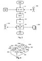
- Fig. 2 shows a flow diagram of an embodiment of the building instruction generation.
- the process receives a digital representation of a building element model, e.g. as created by a model generation module, e.g. the modelling application 110 of fig. 1b , or by any other suitable process.
- a model generation module e.g. the modelling application 110 of fig. 1b
- the digital representation may be retrieved from a storage medium 203, e.g. the local hard disk of the computer running the building instruction application, a CD ROM, a diskette, or the like.
- the digital representation of the model may be stored remotely, e.g. e.g. received from another computer of a computer network where it is stored.
- the digital representation may be downloaded from a web server, where it may be made available to one or more users. Examples of data structures of the digital representation will be described below.
- the building instruction application In subsequent steps S2 - S4, the building instruction application generates a building instruction 205 from the loaded digital representation.
- the building instruction application generates a sequence of 3D views of part-models, where each part-model is distinguished from the immediately preceding part-model in that a predetermined number of additional building elements are added to the model according to a sequence of construction steps determined by the building instruction process as described herein.
- the building instructions 205 may be presented electronically, printed, or presented in another suitable way.
- the generation of the building instructions may be controlled by a user 204. For example, the user may select the number of additional building elements to be added in each step.
- the user may manipulate the generated 3D views, including changes of a camera position, etc., as will be described below.
- the user 204 may be the same or a different user as user 202.
- step S2 the process generates a deconstruction sequence from the received digital representation of the model, e.g. in the form of a sequential list of building elements and/or sub-assemblies of the model.
- the process further generates sub-ordinate deconstruction sequences for the sub-assemblies of the sequential list.
- the process represents the deconstruction sequence as a branched tree of steps where each branch may contain subordinate building deconstructions. An embodiment of a process for generating a deconstruction sequence will be described in greater detail below.
- step S3 the process reverses the generated deconstruction sequence to obtain a construction sequence.
- step S4 the process generates building instructions from the generated construction sequence, e.g. as a sequence of images or other representations of part-models, where in each part-model one or more of the building elements and sub-assemblies from the generated list are added compared to the previous part-model.
- the process may store the generated instructions and/or output them in any suitable form as described herein.
- Fig. 3 shows a flow diagram of an example of a deconstruction process of a model M.
- the deconstruction process deconstructs the model M on the basis of a digital representation of the complete model M, including all the building elements in the model (step 301).
- the input of the model M includes information about the individual building elements, such as size/dimensions, number of knobs, special features such as hinges, pegs, axles etc. of the building elements.
- the digital representation also includes information about where in the model each building element is placed, e.g. by specifying the respective (x,y,z) positions of the building elements with respect to a suitable coordinate system.
- step 302 the deconstruction process tests if there are building elements left in the model M (or a part-model resulting from a previous iteration) to be disconnected. If there are still building elements in the model, the process proceeds at step 303 where the process selects/generates one or more candidate sub-assemblies for removal from the model M.
- the candidate sub-assemblies include interconnected building elements.
- step 304 the process selects a building element or one of the generated candidate sub-assemblies (E) to be disconnected according to a first set of predetermined selection criteria. This first set of predetermined selection criteria assign weights to every building element and generated sub-assembly according to predetermined weight functions, examples of which will be described more thoroughly below.
- the process determines a building element or sub-assembly from a pool of candidates, where the pool includes all individual building elements and the generated candidate sub-assemblies.
- the sub-assemblies may be regarded as being treated as pseudo-building elements in addition to the actual building elements.
- members of the pool of building elements and candidate sub-assemblies will also be referred to as removal candidates.
- the candidate sub-assemblies in step 303 are found/selected by means of a second set of selection criteria, which are a determination of how the model can be separated/cut. Examples of such selection criteria will be described more thoroughly below.
- the process maintains a data structure indicative of the deconstruction sequence, and updates the data structure with information about the disconnected sub-assembly/building element. The sequence is stored, so it can be reversed afterwards to obtain a building instruction.
- the model is completely deconstructed, and the deconstruction process stops in step 308.
- the selection of the "best detachable" brick corresponds to the selection performed in step 304 above, i.e. a selection based on a set of predetermined selection criteria, e.g. one or more of the selection criteria described below.
- the edge data items of the graph data structure may include an attribute indicative of the (physical) connection strength of the corresponding connection between the building elements connected by the connection represented by the edge. So a graph partitioning process for identifying a minimal weight cut of the graph results in a sub-assembly such that the physical strength/force needed to disconnect the sub-assembly is at least approximately minimised. This way, the most loosely connected sub-assemblies are selected. An example of determining the connection strength between building elements will be described in greater detail below.
- Articulation pairs can be found by a process where a list A of all articulation nodes in the connectivity graph G is saved. Then a graph G' is generated, where a non-articulation node n in G is removed. A list B of all articulation nodes in G' is saved. For every node m in B ⁇ A, the following articulation pairs are found: (n, m), This process is repeated for all non-articulation nodes n in the graph G.
- cut-heuristics for identifying candidate sub-assemblies have been disclosed.
- One cut-heuristic or a combination of more cut-heuristics as described above may thus be used during the deconstruction process to efficiently find candidate sub-assemblies among the large number of all possible sub-assemblies of a model.
- each removal candidate - i.e. each of the building elements of the model and each of the candidate sub-assemblies which are selected by the above or alternative cut-heuristics process/es - is weighted by means of one or more weight functions so as to find the removal candidate with the highest weight, i.e. the removal candidate E most suitable to be removed from the model (step 304), and then this selected removal candidate is disconnected (step 305).
- the weight functions are selected such that each weight function will either enhance the chance of a building element/sub-assembly to be selected or it will reject the building elementlsub-assembly from being selected, on basis of the criteria it implements.
- the process combines the results of all weight functions for each building element/sub-assembly so as to obtain an overall weight for the building element/sub-assembly.
- the process may then select the building element/sub-assembly with the highest weight.
- the individual weighting functions are selected according to a uniform weighting scheme, the set of weighting functions is easily changeable.
- each weight function results in a weight.
- a weight is either a real number in the range [0, ..., 1] or a negative integer number (-1, -2, -3, ). If disconnection of a building element/sub-assembly is favoured, the weight assigned to the building element/sub-assembly is in the range [0, ..., 1], where 0 is assigned when it is neither disfavoured nor favoured to disconnect a building element/sub-assembly, and 1 is assigned when disconnection is optimum. The real numbers between these two extremes indicate a disconnection favouring in between.
- the weight function results in a negative weight assigned to the building element/sub-assembly in the range (-1, -2, -3, ...), where the different negative values indicate how disfavoured a disconnection is. It will be appreciated that other sets of weight functions may be defined having different ranges.
- Weight functions having two separate ranges may be used to implement a veto scheme, e.g. as described below:
- An example of how to calculate the stretched geometry/form/shape may comprise finding a direction, which is a vector d, in which the building element can be disconnected.
- the detach process may include the following steps: for every collision volume k in the BE, p1 denotes k's position. p2 denotes k's position when the BE is moved from p1 along the vector d. Since every collision volume is a box with 8 corners, there will be 8 points in p1 and 8 points in p2. In total there will be 16 points in a set of points. When the collision volumes are convex this set of points will constitute a convex figure f.
- the process tests if the figure f collides with any building elements from the model M. If the figure f collides with any building elements from the model M, the building element BE can not be disconnected. If the figure f does not collide with any building elements in the model M, the process can test the next collision volume.
- the building element BE can be disconnected according to the detach strategy.
- weight function avoids disconnection of building elements/sub-assemblies that are physically not (or at least only easily) detachable:
- articulation building elements are strongly disfavoured, thus avoiding flying building elements/sub-assemblies.
- x is not an articulation building element/sub-assembly.
- weight(x) is set to -1 for articulation sub-assemblies and to 0, if x is not an articulation sub-assembly, while in the case of x being an individual building element, weight(x) is set to 0 for articulation building elements and +1 otherwise.
- weight(x) is set to 0 for articulation building elements and +1 otherwise.
- the fast removal of disconnected elements may be favoured by a weight function assigning an increasing weight to building elements/sub-assemblies that are (directly or indirectly) connected to fewer other building elements:
- a weight function assigning an increasing weight to building elements/sub-assemblies that are (directly or indirectly) connected to fewer other building elements:
- the above weight functions assigns the weight 1 to the little gear 801, since it is not connected to any other building elements or sub-assemblies.
- the other building elements are assigned with weight 1/6, because they are part of an assembly including the five elements designated 803, 804, and 805.
- the integration strategy thus reduces the number of steps during which unavoidable "flying" building elements or sub-assemblies are shown in the resulting building instruction.
- Weight functions determine A's and B's coordinates in a coordinate system where the y-axis corresponds to a principle building direction, e.g. a vertical direction.
- the x-axis and z-axis correspond to the other principal building directions, e.g. horizontal directions.
- a weight function for determining if A and B are similar may have the following form:
- a weight higher than 0 reflects some degree of similarity. Alternative and/or additional criteria could also be considered.
- the strategy is to disconnect a building element/sub-assembly, which is similar to the last building elernent/s or sub-assembty/ies disconnected.
- the effect of this strategy is that a model, which contains symmetrical parts, will often be symmetrically deconstructed.
- FIG. 9 An example of the similarity strategy for deconstruction is given in fig. 9 illustrating an example of three consecutive deconstruction steps in figs. 9a )-c), respectively. It is seen from fig. 9 that in the left part of the model, first an oblong building element 901 is disconnected and afterwards a similar oblong building element 902, which is placed in symmetrical relation to the first oblong building element, is disconnected. The next step could be to disconnect the two similar oblong building elements 903 in the right part of the model.
- the connectivity graph may include weights reflecting the physical strength among building elements, as described above, e.g. when each edge has an attribute/weight associated with it indicative of the strength of the corresponding connection.
- each building element may include one or more connection elements for engaging corresponding connection elements of other building elements so as to provide a connection between the building elements.
- fig. 4 shows an example of a building element with protrusions in the form of knobs adapted to engage holes (also referred to as anti-knobs) of another building element.
- building elements may have connection elements of one or more different classes of connection elements, each class of connection element, or each pair of connection element classes, may provide a connection of a corresponding strength. The total strength of a connection between two building elements may thus be determined/estimated from the number of connection elements / pairs of cooperating connection elements that contribute to the connection between two building elements, and from the respective classes/types of the contributing connection elements.
- the process may add the individual connection strengths to obtain a total connection strength.
- Information about the number and types of connection elements contributing to a connection may be obtained from the digital representation of the building element model and/or included in the nodes and/or edges of the connectivity graph. Examples of data structures supporting the definition of connection elements are described in WO 04/034333 .
- connection strength is the connection strength of connection class c
- N(c) is the number of connection elements of class c contributing to the connection between x and y.
- connection elements x and y of the type shown in fig. 4 and having connection elements in the form of knob/anti-knob (or hole) pairs, pegs, and axles may be defined as follows:
- the effective strength of the connectivity may be estimated even more accurately when the calculation of the effective strength further takes the geometry of the building elements into account.
- fig. 10 shows two sub-assemblies, each including two building elements interconnected by a single connection element of the form described in connection with fig. 4 .
- the sub-assembly of fig. 10a is well connected, i.e. difficult to disassemble, the sub-assembly of fig. 10b is not, as it would be very easy for a user to remove building element 1001 from the base plate 1002.
- the process can adjust for this difference by incorporating the volume or mass of the smallest/lightest building element relative to the strength of its connection.
- another suitable quantity indicative of the geometrical properties of the building element may be used. This simulates how easy it is for e.g. a user to grab the building element with the user's fingers, since a large building element is easier to grab than a small building element.
- the two sub-assemblies have the same strength between building elements, because in both cases the small building element is connected in one knob-antiknob pair.
- the smallest building element 1003 has a smaller volume
- the sub-assembly of fig. 10b the smallest building element 1001 has a larger volume, so the function connection(x,y) will be largest for the sub-assembly of fig. 10a .
- the threshold values for the internal and external connections may be predetermined, user-controlled, empirically found or otherwise suitably set. Adjusting the threshold values is an effective way of regulating the amount and quality of substeps in the resulting building instruction. By setting the threshold values to relatively high values, few candidate sub-assemblies of high quality can be obtained instead of obtaining many of lower quality. This makes the deconstruction process easier and faster.
- Building elements which are closer to the previously disconnected building element/sub-assembly may be given higher weight.
- the closest strategy may differentiate between building elements abutting each others surfaces and building elements just contacting each other in their corners, as illustrated in fig 11a and fig 11b , respectively.
- a weight function may thus be an increasing function of the size of the area of abutment between two building elements. Whether or not building elements abut each other or are otherwise in contact with each other may be determined based on bounding box or other geometrical information stored as part of the digital representation. A way of approximating such a measure is by calculating the largest distance between points of the respective building elements. The larger this distance is, the smaller is generally the area of abutment as illustrated by fig. 11 .
- weight functions each corresponding to a corresponding model deconstruction strategy.
- a deconstruction process may include alternative or additional weight functions and/or alternative or additional deconstruction strategies.
- alternative and/or additional weight functions may be defined corresponding to the deconstruction strategies described herein.
- the inventors have obtained particularly good results with a combination of weight functions corresponding to the following strategies in ensuring the integrity of the building deconstruction. Together they may form the backbone of an embodiment of an automatic building instruction generator that provides good results without the need for user interaction:
- the above mentioned four strategies - detach, substep integration, articulation and integration - are used for all construction/deconstruction, whereas one or more further strategies, e.g. one or more of the remaining strategies described herein e.g. similarity, foundation, closest and stacking may be used to adjust the result in different situations.
- Such strategies may be selectable by a user.
- Fig. 4 illustrates an example of a building element and its connection elements.
- fig. 4 shows a perspective view of a building element 401.
- the building element 401 has a top surface 402 with eight knobs 403a-h that can engage with corresponding holes of another building element, e.g. holes on the bottom surface of another building element.
- building element 401 comprises a bottom surface (not shown) with corresponding holes.
- the building element 401 further comprises side faces 404 that do not comprise any connection elements.
- connection elements may be grouped into different classes of connection elements, e.g. connectors, receptors, and mixed elements.
- Connectors are connection elements which may be received by a receptor of another building element, thereby providing a connection between the building elements.
- a connector may fit between parts of another element, into a hole, or the like.
- Receptors are connection elements which can receive a connector of another building element.
- Mixed elements are parts that can function both as a receptor and a connector, typically depending on the type of the cooperating connection element of the other building element.
- Building elements of the type illustrated in fig. 4 are available under the name LEGO in a large variety of shapes, sizes, and colors. Furthermore, such building elements are available with a variety of different connection elements. It is understood that the above building element merely serves as examples of possible building elements.
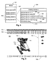
- Fig. 5 illustrates an embodiment of a data structure for digitally representing a building element model.
- the data structure 501 may comprise one or more data records 502 including global model parameters relating to the entire model. Examples of such model parameters include a model name, a name of a model creator, a program version number of the modelling application, a creation date, etc.
- the model data structure 501 further comprises a list 503 or other suitable structure of building element data records.
- the list comprises N data records "Building element 1", "Building element 2", ..., "Building element J", ..., "Building element N".
- Each building element data record of the list 503 has the structure illustrated by the data structure 504 for "Building element J".
- each building element data record comprises a building element ID 505, indicating an identifier corresponding to the type of building element.
- the building element ID may uniquely identify the properties of the building element or type of building element.
- the building element data record may further comprise a number of building element attributes 506 indicating one or more attributes of the building element, such as color, texture, decorations, etc.
- the building element data record 504 comprises data items 507 and 508 representing the position and orientation of an internal coordinate system of the building element, respectively.
- the position and orientation of the building element are defined by the coordinates of an origin of the internal coordinate system of the building element with respect to a global "world" coordinate system, and by the orientation of the internal coordinate system with respect to the global coordinate system.
- the building element data record 504 may comprise data items 509 and 510 representing one or more bounding boxes and connectivity data of the building element, respectively, used in the detection of connectivity properties of the building element with other building elements.
- An embodiment of a representation of the connectivity data of the type of building elements shown in fig. 4 includes data structures representing the planes defined by the surface of a bounding box of the building element.
- the connection elements of the building element are located in these planes, such that each connection element has an axis associated with it.
- the axes of all connection elements in the same plane correspond to respective grid points of a regular grid, e.g. an orthogonal grid, with fixed distances between neighbouring grid points.
- the distances between neighbouring grid points may be the same in all horizontal planes. In some embodiments, the distances between neighbouring grid points in vertical planes are different from the distances between neighbouring grid points in horizontal planes.
- a digital representation of the connectivity properties of the building elements of the type shown in fig. 4 are disclosed in WO 04/034333 .
- digital representation may be encoded in any suitable data or file format, e.g. as a binary file, as a text file according to predetermined modelling description language, or the like. It will further be understood that other embodiments of digital information may utilise alternative or additional data structures and/or represent alternative or additional model data.
- Fig. 6 illustrates an embodiment of a graphical user-interface of a building instruction application program.
- the user-interface comprises a viewing area 701 illustrating a graphical representation of a step of a set of step-by-step building instructions.
- the graphical representation shows a 3D view of a part-model 702 shown from a predetermined camera position.
- the part-model 702 consists of a subset of all the building elements of the complete model, where the subset includes the initially positioned building elements.
- the viewing area 701 further comprises a graphical representation 703 of the most recently placed building elements, i.e. the building elements that distinguish the present part-model 702 from the part-model of the previous step. In this example, these are the building elements 714, 715, and 716 of the part-model 702.
- the user-interface further comprises a slider control element 709 which may be moved in discrete intervals by a corresponding drag operation with the mouse, allowing a user to select any of the steps of the step-by-step instructions.
- a slider control element 709 which may be moved in discrete intervals by a corresponding drag operation with the mouse, allowing a user to select any of the steps of the step-by-step instructions.
- three new building elements are added in each step of the instructions.
- the user-interface further comprises button control elements 705 that allow a user to invoke a number of frequently used functions such as sequentially flipping through the graphical representations in a forward and backward direction, respectively, jumping to the first and last step of the instructions, changing the camera position, printing the generated building instructions, and initiating an "auto-play" function.
- the auto-play function displays the sequence of part-models one by one such that each part-model is shown for a predetermined period of time.
- the user may configure the viewing time for each part-model in the auto-play function.
- the user interface comprises a number of pull-down menus 704, allowing a user to initiate functionality such as a help function, functions for changing the camera position, zoom functions, etc.
- Further functionality provided by the building instruction application includes the loading of digital representations, a print function for printing the graphical representations of the part-models, and export functions for exporting the sequence of graphical representations of the part-models, e.g. in a HTML format, or any other suitable graphical file format, such as TIF, JPG, BMP, etc.
- functions provided by the building instruction application include a bill of material function, allowing a user to view or print a list of all building elements in the model.
- Fig. 14 shows a flow diagram of another embodiment of the building instruction generation.
- the process receives a digital representation M of a building element model, e.g. as described in connection with step S1 of fig. 2 .
- the building instruction application In subsequent steps S2 - S12, the building instruction application generates a building instruction 205 from the loaded digital representation.
- the generated building instruction 205 may be in a form as described in connection with fig. 2 .
- step S2 the process initialises the process.
- the process initialises a data structure Result for holding the construction sequence to be generated.
- the process initialises the sequence Result to be an empty sequence.
- the process further initialises a set of candidate building elements, denoted Candidates , to be the set of all building elements and sub-assemblies in the model M.
- the process may determine or more candidate sub-assemblies for removal from the model M and treat sub-assemblies as generalised building elements.
- the candidate sub-assemblies may be found/selected by means of a set of selection criteria, which are a determination of how the model can be separated/cut. Examples of such selection criteria have been described more thoroughly above, in particular the second set of selection criteria described in connection with step 303 of fig. 3 . It will be appreciated that in other embodiments, the process may only consider building elements.
- step S3 the process determines whether the set Candidates is empty, i.e. whether all building elements have been processed. If this is the case, the process proceeds at step S12; otherwise the process proceeds at step S4.
- steps S4-S11 the process determines whether a construction step b resulting in a new part model can be found such that the full model M can be deconstructed down to this new part model.
- step S4 the process generates an auxiliary set C of building elements and sub-assembly as a copy of the set Candidates .
- step S5 the process determines whether the set C is empty, i.e. whether a candidate b has been identified. If this is the case, the process returns to step S3; otherwise the process proceeds at step S6.
- step S6 the process selects a candidate building element b - or a candidate sub-assembly - from the set C.
- the selection of candidates in the present embodiment may be done in a similar fashion as the selection of a building element for removal in the deconstruction case of the previous embodiment, i.e. by means of a set of selection criteria.
- the selection criteria may be based on one or more weight functions representing different building strategies such as one or more of the weight functions described above, in particular the weight functions of first set of selection criteria described in connection with step 304 of fig. 3 .
- Some weight functions may be identical or almost identical in the constructive and deconstructive versions, respectively, e.g. as the weight functions described in greater detail above.
- one strategy may assign a weight to building elements according to their distance from the building element added in the previous step. The process may then select the closest building element to the previously added building element.
- weight functions may be quite different.
- the 'articulation strategy' in the deconstruction case described above avoids breaking the connectivity graph, whereas in the constructive case of the present embodiment it simply ensures that a building element is selected which actually connects to any previously selected building element. Nevertheless, in both cases "flying" building elements are avoided.
- the weight functions described herein may weight sub-assemblies (pseudo-building-elements) as well as simple building elements, both the constructive and the deconstructive process may be generalized to handle sub-assemblies. As in the pure destructive case, this is not only practical but sometime desirable.
- the selection of a candidate may partly or completely be based on a user input/interaction.
- the process may receive a user input indicative of a candidate b.
- the process may select, e.g. randomly or based on the weight functions described above, one or more possible candidates and indicate the candidate(s) to the user, The process may then receive a user input indicative of an approval or rejection of the one or more suggested candidates.
- step S7 the process generates a partial deconstruction sequence from the received digital representation of the model down to the residual model obtainable by the union of the current construction sequence Result and the selected candidate b.
- the deconstruction sequence may be generated in the form of a sequential list of building elements and/or sub-assemblies of the model.
- the process may further generate sub-ordinate deconstruction sequences for the sub-assemblies of the sequential list.
- the process represents the deconstruction sequence as a branched tree of steps where each branch may contain subordinate building deconstructions. An embodiment of a process for generating a partial deconstruction sequence will be described in greater detail below.
- step S8 the process determines whether a deconstruction sequence could be found. If the deconstruction process of step S7 succeeds in determining a deconstruction sequence, the process proceeds at step S9; otherwise the process proceeds at step S10.
- the process updates the sets Candidates , Result, and C.
- the process adds the selected candidate b to the current result sequence Result, removes the candidate b from the set of candidates Candidates, and removes all elements from the auxiliary set C (as a successful candidate has been identified). The process then returns to S5.
- step S10 the process removes b from the auxiliary set C of candidates yet to try.
- step S11 the process determines whether there are still candidates left in C. If this is the case, the process returns to step S5 to identify an alternative candidate; otherwise the process terminates, e.g. with a suitable error flag or message indicating that generating a constructive building instruction failed. For example, this situation may occur if the model is over-constrained and/or if the weight functions used during the deconstruction process representing the building constraints of the model are too strong/restrictive. Hence, in such cases, some or all of the weight functions used in the deconstruction process may be relaxed/weakened, e.g. automatically or by a user interaction, and the process may be re-started with the relaxed weight functions.
- step S12 the process generates building instructions from the generated construction sequence Result, e.g. as a sequence of images or other representations of part-models, where in each part-model one or more of the building elements and sub-assemblies from the generated list Result are added compared to the previous part-model.
- the process may store the generated instructions and/or output them in any suitable form as described herein.
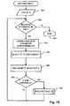
- Fig. 15 shows a flow diagram of an example of a partial deconstruction process of a model M down to a residual model N.
- the deconstruction process deconstructs the model M on the basis of a digital representation of the complete model M, including all the building elements in the model (step 301).
- the input of the model M includes information about the individual building elements, such as size/dimensions, number of knobs, special features such as hinges, pegs, axles etc. of the building elements.
- the digital representation also includes information about where in the model each building element is placed, e.g. by specifying the respective ( x,y,z ) positions of the building elements with respect to a suitable coordinate system.
- the process further receives information about the residual set N, i.e. a sub-model of the model M.
- the partial deconstruction process generates a sequence of deconstruction steps, where in each deconstruction step one or more building elements of M ⁇ N (i.e. building elements of the model M that are not included in the residual model N )
- step 302 the deconstruction process tests if there are building elements left in the model M ⁇ N (or a part-model M' ⁇ N resulting from a previous iteration) to be disconnected. If there are still building elements to be removed in the model, the process proceeds at step 303 where the process selects/generates one or more candidate sub-assemblies for removal from the model M ⁇ N (or a part-model M' ⁇ N resulting from a previous iteration).
- the candidate sub-assemblies include interconnected building elements.
- step 304 the process selects a building element or one of the generated candidate sub-assemblies ( E ) to be disconnected according to a first set of predetermined selection criteria, e.g. as described in connection with fig. 3 .
- the candidate sub-assemblies in step 303 may be found/selected by means of a second set of selection criteria, which are a determination of how the model can be separated/cut. Examples of such selection criteria have been described more thoroughly above.
- the process may maintain a data structure indicative of the deconstruction sequence, and update the data structure with information about the disconnected sub-assembly/building element.
- N can be constructed into M.
- a construction at stage N is a suitable intermediate model during a sequqnec of construction steps, if (and only if) the full model M can be deconstructed down to it.
- the embodiment of a process for generating a construction sequence described in connection with figs. 14 and 15 may be expressed by the following pseudo-code:
- the selection of the "best detachable" brick corresponds to the selection performed in step 304 above, i.e. a selection based on a set of predetermined selection criteria, e.g. one or more of the selection criteria described above.
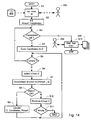
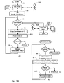
- An embodiment of the process may also be expressed by the following pseudo-code; a flow diagram of this embodiment is shown in fig. 16 :
- Fig. 16a shows the overall process
- fig. 16b shows a flow diagram of an example of the function that identifies a possible/valid next construction step.
- step S3 the process determines whether the set Candidates is empty, i.e. whether all building elements have been processed. If this is the case, the process proceeds at step S12 with the generation of the building instructions as described above; otherwise the process proceeds at step S4.
- step S4 the process generates an auxiliary set C of building elements and sub-assembly as a copy of the set Candidates.
- step S20 the process determines whether a valid next construction step b can be found. If this is the case, the process updates the Results and Candidates data structures, by appending the identified step b to the Results data structure, and by removing the corresponding building element (or subassembly) from the Candidates data structure; the process then returns to step S3. If no valid construction step can be found, the process terminates, e.g. with a suitable error flag or message indicating that generating a constructive building instruction failed, as described in connection with fig. 14 .
- Fig. 16a shows a flow diagram of an example of sub-process implementing step S20: Initially, the process determines whether the set C is empty, i.e. whether all candidates b have been processed. If this is the case, the process returns a value indicating that no valid candidate b could found; otherwise the process proceeds at step S6.
- step S6 the process selects a candidate building element b - or a candidate sub-assembly - from the set C, e.g. as described in connection with step S6 of fig. 14 .
- step S7 the process generates a partial deconstruction sequence from the received digital representation of the model down to the residual model obtainable by the union of the current construction sequence Result and the selected candidate b , as described in connection with step S7 of fig. 14 .
- step S7 If the deconstruction process of step S7 succeeds in determining a deconstruction sequence, the process returns a value indicating that the process was successful; otherwise the process proceeds at step S10.
- step S10 the process removes b from the auxiliary set C of candidates yet to try, and returns to the beginning of the sub-process to determine whether C is empty.
- the function "Deconstruct model M down to N" may be the same function as in the above example.
- a construction of a model with N building elements takes N construction-steps, and generally for each construction-step, several deconstructions may have to be run in order to find a candidate brick b that is valid.
- a full constructive building instruction of N bricks needs approximately N construction-steps.
- Each construction-step may need approximately N / 2 deconstructions.
- Each deconstruction consists of approximately N deconstruction-steps.
- Each deconstruction-step requires approximately N / 2 brick weightings.
- a full constructive Building Instruction may require up to approximately (N ⁇ 4) / 4 weightings of building elements. This is still much better than the x ⁇ N weightings required for a pure backtracking-search.
- the full deconstructive process described in connection with figs 2 and 3 requires approximately (N ⁇ 2) / 2 weightings.
Landscapes
- Engineering & Computer Science (AREA)
- Physics & Mathematics (AREA)
- Theoretical Computer Science (AREA)
- Computer Graphics (AREA)
- Software Systems (AREA)
- General Physics & Mathematics (AREA)
- Geometry (AREA)
- Architecture (AREA)
- Computer Hardware Design (AREA)
- General Engineering & Computer Science (AREA)
- Processing Or Creating Images (AREA)
- Toys (AREA)
- Electrophonic Musical Instruments (AREA)
- Management, Administration, Business Operations System, And Electronic Commerce (AREA)
- Stored Programmes (AREA)
Applications Claiming Priority (2)
| Application Number | Priority Date | Filing Date | Title |
|---|---|---|---|
| US11/724,915 US7979251B2 (en) | 2007-03-16 | 2007-03-16 | Automatic generation of building instructions for building element models |
| PCT/EP2008/053124 WO2008113768A1 (en) | 2007-03-16 | 2008-03-14 | Automatic generation of building instructions for building element models |
Publications (2)
| Publication Number | Publication Date |
|---|---|
| EP2135222A1 EP2135222A1 (en) | 2009-12-23 |
| EP2135222B1 true EP2135222B1 (en) | 2010-08-25 |
Family
ID=39473765
Family Applications (1)
| Application Number | Title | Priority Date | Filing Date |
|---|---|---|---|
| EP08717863A Active EP2135222B1 (en) | 2007-03-16 | 2008-03-14 | Automatic generation of building instructions for building element models |
Country Status (13)
| Country | Link |
|---|---|
| US (1) | US7979251B2 (da) |
| EP (1) | EP2135222B1 (da) |
| JP (1) | JP2010521727A (da) |
| KR (1) | KR101470665B1 (da) |
| CN (1) | CN101675458B (da) |
| AT (1) | ATE479167T1 (da) |
| BR (1) | BRPI0808986B1 (da) |
| CA (1) | CA2680256C (da) |
| DE (1) | DE602008002331D1 (da) |
| DK (1) | DK2135222T3 (da) |
| ES (1) | ES2351272T3 (da) |
| MX (1) | MX2009009733A (da) |
| WO (1) | WO2008113768A1 (da) |
Cited By (2)
| Publication number | Priority date | Publication date | Assignee | Title |
|---|---|---|---|---|
| WO2013080206A1 (en) * | 2011-11-29 | 2013-06-06 | Wainztein Amitay | Building unit toy |
| US10204184B2 (en) | 2015-01-27 | 2019-02-12 | Electronics And Telecommunications Research Institute | Apparatus and method for modeling cultural heritage building |
Families Citing this family (54)
| Publication number | Priority date | Publication date | Assignee | Title |
|---|---|---|---|---|
| US7979251B2 (en) * | 2007-03-16 | 2011-07-12 | Lego A/S | Automatic generation of building instructions for building element models |
| US8374829B2 (en) * | 2007-03-16 | 2013-02-12 | Lego A/S | Automatic generation of building instructions for building element models |
| US9087164B2 (en) * | 2008-01-26 | 2015-07-21 | National Semiconductor Corporation | Visualization of tradeoffs between circuit designs |
| US7966588B1 (en) * | 2008-01-26 | 2011-06-21 | National Semiconductor Corporation | Optimization of electrical circuits |
| US8334893B2 (en) * | 2008-11-07 | 2012-12-18 | Honeywell International Inc. | Method and apparatus for combining range information with an optical image |
| WO2011026268A1 (en) | 2009-09-02 | 2011-03-10 | Autodesk, Inc. | Automatic explode based on occlusion |
| CN105373651B (zh) * | 2009-09-02 | 2019-01-18 | 欧特克公司 | 基于遮断的自动分解 |
| US8628393B1 (en) * | 2009-09-24 | 2014-01-14 | Autodesk, Inc. | 3D puzzle generation, algorithms for generation, and physical instantiations |
| BR112012007559B1 (pt) * | 2009-10-02 | 2021-04-27 | Lego A/S | Método implementado por computador para visualizar/renderizar um modelo de computador |
| JP5628083B2 (ja) * | 2011-04-13 | 2014-11-19 | 株式会社日立製作所 | 計算機システム、及び組立アニメーション生成方法 |
| PL2714223T3 (pl) * | 2011-05-23 | 2015-10-30 | Lego As | Generowanie instrukcji budowania dla modeli z konstrukcyjnych elementów |
| BR112013029916B1 (pt) | 2011-05-23 | 2021-02-09 | Lego Ns | sistema de construção de brinquedo, método implementado por computador para gerar uma imagem de um modelo de construção de brinquedo, sistema de processamento de dados, meio legível por computador, e conjunto de construção de brinquedo |
| CN102401334B (zh) * | 2011-11-18 | 2013-11-27 | 深圳市华星光电技术有限公司 | 平板显示装置的背框以及背光系统 |
| JP6098120B2 (ja) * | 2012-11-01 | 2017-03-22 | 富士通株式会社 | 組立順序生成プログラム、組立順序生成装置、および製造方法 |
| KR101441230B1 (ko) * | 2013-01-22 | 2014-09-17 | 울산대학교 산학협력단 | 부품의 조립순서 자동 생성방법 및 장치 |
| CN104123306B (zh) * | 2013-04-27 | 2019-06-25 | 厦门雅迅网络股份有限公司 | 一种基于历史分析的无人智能驱动的数据文件生成方法 |
| US10583588B2 (en) | 2013-06-21 | 2020-03-10 | Pavestone, LLC | Manufactured retaining wall block with improved false joint |
| US9701046B2 (en) | 2013-06-21 | 2017-07-11 | Pavestone, LLC | Method and apparatus for dry cast facing concrete deposition |
| USD791346S1 (en) | 2015-10-21 | 2017-07-04 | Pavestone, LLC | Interlocking paver |
| KR101735683B1 (ko) * | 2014-01-07 | 2017-05-15 | 한국전자통신연구원 | 목조 건조물 조립 시뮬레이션 장치 및 그 방법 |
| US9517423B1 (en) | 2014-02-13 | 2016-12-13 | Maurice S. Kanbar Revocable Trust | Toy construction set |
| USD737468S1 (en) | 2014-05-07 | 2015-08-25 | Pavestone, LLC | Front face of a retaining wall block |
| US10583354B2 (en) | 2014-06-06 | 2020-03-10 | Lego A/S | Interactive game apparatus and toy construction system |
| KR102435699B1 (ko) | 2014-10-02 | 2022-08-25 | 레고 에이/에스 | 게임 시스템 |
| US10379524B2 (en) * | 2015-06-26 | 2019-08-13 | The Boeing Company | Management of a display of an assembly model |
| US9814997B1 (en) | 2015-07-23 | 2017-11-14 | Mega Brands Inc. | Toy construction element with moving members |
| US9947140B2 (en) * | 2015-09-15 | 2018-04-17 | Sartorius Stedim Biotech Gmbh | Connection method, visualization system and computer program product |
| USD786984S1 (en) | 2015-10-15 | 2017-05-16 | Mega Brands Inc. | Construction set element |
| US10102768B2 (en) * | 2016-03-19 | 2018-10-16 | Fujitsu Limited | Behavior variability and complexity modeling using a construction toy |
| US10650222B2 (en) * | 2016-05-09 | 2020-05-12 | Lego A/S | System and method for toy recognition |
| CN109562294A (zh) * | 2016-07-05 | 2019-04-02 | 乐高公司 | 用于创建虚拟对象的方法 |
| US11430195B2 (en) | 2016-08-31 | 2022-08-30 | Sony Corporation | Information processing apparatus, information processing method, and program for improving user-friendliness of an animated tutorial depicting assembling parts for creating a robot |
| WO2018195583A1 (en) * | 2017-04-26 | 2018-11-01 | Emmet Pty Ltd | Construction system and method |
| USD844394S1 (en) | 2018-03-29 | 2019-04-02 | Kraft Foods Group Brands Llc | Mold |
| US10894342B2 (en) | 2018-03-29 | 2021-01-19 | Kraft Foods Group Brands Llc | System and method for molding comestible building blocks |
| JP7022640B2 (ja) * | 2018-03-30 | 2022-02-18 | Kddi株式会社 | 経路探索装置、経路探索方法及びコンピュータプログラム |
| CN108549624B (zh) * | 2018-04-18 | 2021-08-27 | 宁夏通信规划设计院(有限责任公司) | 通信工程设计预算和说明文本自动化生成系统和方法 |
| US12030185B2 (en) * | 2018-11-09 | 2024-07-09 | Autodesk, Inc. | Techniques for CAD-informed robotic assembly |
| JP6539000B1 (ja) * | 2019-02-13 | 2019-07-03 | 株式会社白紙とロック | 複数個体の数値演算システム、数値演算方法、プログラム |
| KR102433186B1 (ko) * | 2019-04-12 | 2022-08-18 | 레고 에이/에스 | 안정성 체크 장치, 방법 및 컴퓨터 프로그램 제품 |
| KR102341778B1 (ko) * | 2019-04-12 | 2021-12-22 | 레고 에이/에스 | 조립식 완구의 조립 순서 결정 및 매뉴얼 생성 방법 |
| CN110175366A (zh) * | 2019-04-26 | 2019-08-27 | 南京友谱信息科技有限公司 | 区域级构筑及建筑整体透视三维模型建模方法 |
| US11423799B2 (en) * | 2019-07-03 | 2022-08-23 | Rockwell Automation Technologies, Inc. | Systems and methods for generating custom assembly instructions for product packages |
| US11029805B2 (en) | 2019-07-10 | 2021-06-08 | Magic Leap, Inc. | Real-time preview of connectable objects in a physically-modeled virtual space |
| CN111179422B (zh) * | 2019-12-31 | 2023-08-04 | 深圳市优必选科技股份有限公司 | 一种模型构建方法、装置及终端设备 |
| DK181187B1 (da) | 2021-03-25 | 2023-04-13 | Lego As | Modulær konstruktionssystemsmotorenhed til modulært konstruktions-system |
| CN113032889B (zh) * | 2021-05-31 | 2022-03-01 | 北京盈建科软件股份有限公司 | 由基础结构和上部结构拼接成联合建筑模型的方法及其装置 |
| CN113742808B (zh) * | 2021-09-08 | 2024-03-26 | 深圳千帜科技有限公司 | 一种拼装积木模型设计方法 |
| CN114042311A (zh) * | 2021-11-15 | 2022-02-15 | 中国联合网络通信集团有限公司 | 信息处理方法、边缘服务器、电子设备、计算机介质 |
| USD1037491S1 (en) | 2021-12-14 | 2024-07-30 | Pavestone, LLC | Wall block |
| CN114896812B (zh) * | 2022-06-08 | 2024-08-02 | 深圳千帜科技有限公司 | 一种积木打印的自动排版方法、设备、存储介质及系统 |
| DE102022118246B4 (de) | 2022-07-21 | 2025-03-20 | Dr. Ing. H.C. F. Porsche Aktiengesellschaft | System, Verfahren und Computerprogrammprodukt zur Optimierung der Anzahl von Produktvarianten eines Produkts |
| CN115364494B (zh) * | 2022-07-26 | 2024-02-23 | 福州市鹭羽智能科技有限公司 | 一种基于图样的积木自动堆放装置及方法 |
| CN118505936B (zh) * | 2024-07-19 | 2024-10-22 | 汕头市高砖文化科技有限公司 | 一种3d模型积木化智能转换和搭建系统 |
Family Cites Families (21)
| Publication number | Priority date | Publication date | Assignee | Title |
|---|---|---|---|---|
| JP3024350B2 (ja) * | 1991-04-04 | 2000-03-21 | 株式会社日立製作所 | 製造性自動評価方法およびシステム |
| US6004021A (en) | 1995-09-28 | 1999-12-21 | Chaos, L.L.C. | Toy system including hardware toy pieces and toy design software for designing and building various toy layouts using the hardware toy pieces |
| JPH10240324A (ja) * | 1997-02-27 | 1998-09-11 | Toshiba Corp | 組立順序抽出方法及びその装置 |
| EP0972272B1 (en) | 1997-04-03 | 2003-08-13 | Intergraph Corporation | Interactive timeline visualization |
| AU2382300A (en) * | 1998-12-23 | 2000-07-12 | National Institute Of Standards And Technology ("Nist") | Method and system for a virtual assembly design environment |
| US6389375B1 (en) | 1999-01-22 | 2002-05-14 | Interlego Ag | Virtual reality modelling |
| US6725184B1 (en) * | 1999-06-30 | 2004-04-20 | Wisconsin Alumni Research Foundation | Assembly and disassembly sequences of components in computerized multicomponent assembly models |
| JP2002117107A (ja) * | 1999-09-02 | 2002-04-19 | Ricoh Co Ltd | 生産管理システム、生産管理システムにおけるクライアント、生産管理システムにおける生産管理方法、生産管理システムにおけるデータ検索方法、およびその方法を実行させるためのプログラムを記録したコンピュータが読取可能な記録媒体 |
| US6859768B1 (en) * | 2000-03-03 | 2005-02-22 | The Beck Technology | Computer-implemented automated building design and modeling and project cost estimation and scheduling system |
| JP2001353631A (ja) * | 2000-06-09 | 2001-12-25 | Ricoh Co Ltd | 組立工程設計支援装置および分解工程設計支援装置 |
| US6826500B2 (en) * | 2001-06-29 | 2004-11-30 | General Electric Company | Method and system for automated maintenance and training instruction generation and validation |
| US20030097195A1 (en) * | 2001-11-20 | 2003-05-22 | General Electric Company | Method for computing disassembly sequences from geometric models |
| JP4509789B2 (ja) | 2002-10-11 | 2010-07-21 | レゴ エー/エス | コンピュータ読み取り可能なモデル |
| WO2004068300A2 (en) * | 2003-01-25 | 2004-08-12 | Purdue Research Foundation | Methods, systems, and data structures for performing searches on three dimensional objects |
| US7596473B2 (en) * | 2003-05-20 | 2009-09-29 | Interlego Ag | Method of constructing a virtual construction model |
| US7480597B2 (en) | 2003-05-20 | 2009-01-20 | Lego A/S | Method, system and storage medium for generating virtual brick models |
| US20070262984A1 (en) | 2004-06-17 | 2007-11-15 | Lego A/S | Automatic Generation of Building Instructions for Building Block Models |
| US7660641B2 (en) * | 2004-07-21 | 2010-02-09 | International Business Machines Corporation | System, graphical user interface (GUI), method and program product for configuring an assembly line |
| US7295201B2 (en) * | 2005-09-29 | 2007-11-13 | General Electronic Company | Method and system for generating automated exploded views |
| US7680554B2 (en) * | 2006-12-19 | 2010-03-16 | International Business Machines Corporation | Method for associating objects in a manufacturing process |
| US7979251B2 (en) * | 2007-03-16 | 2011-07-12 | Lego A/S | Automatic generation of building instructions for building element models |
-
2007
- 2007-03-16 US US11/724,915 patent/US7979251B2/en active Active
-
2008
- 2008-03-14 WO PCT/EP2008/053124 patent/WO2008113768A1/en not_active Ceased
- 2008-03-14 CN CN200880014715.5A patent/CN101675458B/zh active Active
- 2008-03-14 KR KR1020097021645A patent/KR101470665B1/ko active Active
- 2008-03-14 AT AT08717863T patent/ATE479167T1/de active
- 2008-03-14 DE DE602008002331T patent/DE602008002331D1/de active Active
- 2008-03-14 MX MX2009009733A patent/MX2009009733A/es active IP Right Grant
- 2008-03-14 BR BRPI0808986-8 patent/BRPI0808986B1/pt active IP Right Grant
- 2008-03-14 EP EP08717863A patent/EP2135222B1/en active Active
- 2008-03-14 DK DK08717863.8T patent/DK2135222T3/da active
- 2008-03-14 CA CA2680256A patent/CA2680256C/en active Active
- 2008-03-14 ES ES08717863T patent/ES2351272T3/es active Active
- 2008-03-14 JP JP2009553161A patent/JP2010521727A/ja active Pending
Non-Patent Citations (1)
| Title |
|---|
| ALLERELLI J: "Computer-aided generation of building instructions for LEGO models", THESIS, 1 June 2006 (2006-06-01), Department of Mathematics and Computer Science, University of Southern Denmark, pages 1 - 130, XP007905065 * |
Cited By (2)
| Publication number | Priority date | Publication date | Assignee | Title |
|---|---|---|---|---|
| WO2013080206A1 (en) * | 2011-11-29 | 2013-06-06 | Wainztein Amitay | Building unit toy |
| US10204184B2 (en) | 2015-01-27 | 2019-02-12 | Electronics And Telecommunications Research Institute | Apparatus and method for modeling cultural heritage building |
Also Published As
| Publication number | Publication date |
|---|---|
| KR20090125272A (ko) | 2009-12-04 |
| US7979251B2 (en) | 2011-07-12 |
| JP2010521727A (ja) | 2010-06-24 |
| CA2680256C (en) | 2016-02-23 |
| BRPI0808986B1 (pt) | 2019-12-03 |
| CA2680256A1 (en) | 2008-09-25 |
| HK1138092A1 (zh) | 2010-08-13 |
| DK2135222T3 (da) | 2010-12-13 |
| US20080228450A1 (en) | 2008-09-18 |
| BRPI0808986A2 (pt) | 2014-09-09 |
| CN101675458A (zh) | 2010-03-17 |
| CN101675458B (zh) | 2016-02-24 |
| WO2008113768A1 (en) | 2008-09-25 |
| ATE479167T1 (de) | 2010-09-15 |
| EP2135222A1 (en) | 2009-12-23 |
| MX2009009733A (es) | 2009-11-09 |
| DE602008002331D1 (de) | 2010-10-07 |
| ES2351272T3 (es) | 2011-02-02 |
| KR101470665B1 (ko) | 2014-12-08 |
Similar Documents
| Publication | Publication Date | Title |
|---|---|---|
| EP2135222B1 (en) | Automatic generation of building instructions for building element models | |
| US8374829B2 (en) | Automatic generation of building instructions for building element models | |
| US10596479B2 (en) | Method and system for designing and producing a user-defined toy construction element | |
| Aouad et al. | Computer aided design guide for architecture, engineering and construction | |
| KR101071011B1 (ko) | 3차원 대상물의 디지털 표시를 조작하기 위한 방법 및시스템 | |
| US20070262984A1 (en) | Automatic Generation of Building Instructions for Building Block Models | |
| US20190196449A1 (en) | Determining manufacturable models | |
| Zhang et al. | Functionality-aware retargeting of mechanisms to 3D shapes | |
| Kim et al. | Puzzle-Level Generation with Simple-tiled and Graph-based Wave Function Collapse Algorithms | |
| Boa et al. | Evolving lego: Prototyping requirements for a customizable construction kit | |
| HK1138092B (en) | Automatic generation of building instructions for building element models | |
| Mahmudi et al. | Multi-modal data-driven motion planning and synthesis | |
| WO2025233314A1 (en) | Generation of toy construction models | |
| Westfalen | Procedural generation of buildings with wave function collapse and marching cubes | |
| Hemberg et al. | Exploring generative growth and evolutionary computation for architectural design | |
| Cha et al. | Computational Design of Shape-Aware Sieves | |
| Rabasa Galan | Procedural generation tool for grid-designed modular assets | |
| Whiteley et al. | Tangible-Tango: Designing and Fabricating Tangibles with Tangibles. | |
| HK1193066B (en) | Method and system for designing and producing a user-defined toy construction element | |
| HK1115505A (en) | Automatic generation of building instructions for building block models |
Legal Events
| Date | Code | Title | Description |
|---|---|---|---|
| PUAI | Public reference made under article 153(3) epc to a published international application that has entered the european phase |
Free format text: ORIGINAL CODE: 0009012 |
|
| 17P | Request for examination filed |
Effective date: 20090921 |
|
| AK | Designated contracting states |
Kind code of ref document: A1 Designated state(s): AT BE BG CH CY CZ DE DK EE ES FI FR GB GR HR HU IE IS IT LI LT LU LV MC MT NL NO PL PT RO SE SI SK TR |
|
| GRAP | Despatch of communication of intention to grant a patent |
Free format text: ORIGINAL CODE: EPIDOSNIGR1 |
|
| DAX | Request for extension of the european patent (deleted) | ||
| GRAS | Grant fee paid |
Free format text: ORIGINAL CODE: EPIDOSNIGR3 |
|
| GRAA | (expected) grant |
Free format text: ORIGINAL CODE: 0009210 |
|
| AK | Designated contracting states |
Kind code of ref document: B1 Designated state(s): AT BE BG CH CY CZ DE DK EE ES FI FR GB GR HR HU IE IS IT LI LT LU LV MC MT NL NO PL PT RO SE SI SK TR |
|
| REG | Reference to a national code |
Ref country code: GB Ref legal event code: FG4D |
|
| REG | Reference to a national code |
Ref country code: CH Ref legal event code: EP |
|
| REG | Reference to a national code |
Ref country code: IE Ref legal event code: FG4D |
|
| REF | Corresponds to: |
Ref document number: 602008002331 Country of ref document: DE Date of ref document: 20101007 Kind code of ref document: P |
|
| REG | Reference to a national code |
Ref country code: NL Ref legal event code: T3 |
|
| REG | Reference to a national code |
Ref country code: DK Ref legal event code: T3 |
|
| REG | Reference to a national code |
Ref country code: SE Ref legal event code: TRGR |
|
| LTIE | Lt: invalidation of european patent or patent extension |
Effective date: 20100825 |
|
| PG25 | Lapsed in a contracting state [announced via postgrant information from national office to epo] |
Ref country code: LT Free format text: LAPSE BECAUSE OF FAILURE TO SUBMIT A TRANSLATION OF THE DESCRIPTION OR TO PAY THE FEE WITHIN THE PRESCRIBED TIME-LIMIT Effective date: 20100825 Ref country code: NO Free format text: LAPSE BECAUSE OF FAILURE TO SUBMIT A TRANSLATION OF THE DESCRIPTION OR TO PAY THE FEE WITHIN THE PRESCRIBED TIME-LIMIT Effective date: 20101125 |
|
| REG | Reference to a national code |
Ref country code: ES Ref legal event code: FG2A Effective date: 20110121 |
|
| PG25 | Lapsed in a contracting state [announced via postgrant information from national office to epo] |
Ref country code: IS Free format text: LAPSE BECAUSE OF FAILURE TO SUBMIT A TRANSLATION OF THE DESCRIPTION OR TO PAY THE FEE WITHIN THE PRESCRIBED TIME-LIMIT Effective date: 20101225 Ref country code: HR Free format text: LAPSE BECAUSE OF FAILURE TO SUBMIT A TRANSLATION OF THE DESCRIPTION OR TO PAY THE FEE WITHIN THE PRESCRIBED TIME-LIMIT Effective date: 20100825 Ref country code: CY Free format text: LAPSE BECAUSE OF FAILURE TO SUBMIT A TRANSLATION OF THE DESCRIPTION OR TO PAY THE FEE WITHIN THE PRESCRIBED TIME-LIMIT Effective date: 20100825 Ref country code: BG Free format text: LAPSE BECAUSE OF FAILURE TO SUBMIT A TRANSLATION OF THE DESCRIPTION OR TO PAY THE FEE WITHIN THE PRESCRIBED TIME-LIMIT Effective date: 20101125 Ref country code: SI Free format text: LAPSE BECAUSE OF FAILURE TO SUBMIT A TRANSLATION OF THE DESCRIPTION OR TO PAY THE FEE WITHIN THE PRESCRIBED TIME-LIMIT Effective date: 20100825 Ref country code: PL Free format text: LAPSE BECAUSE OF FAILURE TO SUBMIT A TRANSLATION OF THE DESCRIPTION OR TO PAY THE FEE WITHIN THE PRESCRIBED TIME-LIMIT Effective date: 20100825 |
|
| PG25 | Lapsed in a contracting state [announced via postgrant information from national office to epo] |
Ref country code: GR Free format text: LAPSE BECAUSE OF FAILURE TO SUBMIT A TRANSLATION OF THE DESCRIPTION OR TO PAY THE FEE WITHIN THE PRESCRIBED TIME-LIMIT Effective date: 20101126 Ref country code: LV Free format text: LAPSE BECAUSE OF FAILURE TO SUBMIT A TRANSLATION OF THE DESCRIPTION OR TO PAY THE FEE WITHIN THE PRESCRIBED TIME-LIMIT Effective date: 20100825 |
|
| PG25 | Lapsed in a contracting state [announced via postgrant information from national office to epo] |
Ref country code: SK Free format text: LAPSE BECAUSE OF FAILURE TO SUBMIT A TRANSLATION OF THE DESCRIPTION OR TO PAY THE FEE WITHIN THE PRESCRIBED TIME-LIMIT Effective date: 20100825 Ref country code: EE Free format text: LAPSE BECAUSE OF FAILURE TO SUBMIT A TRANSLATION OF THE DESCRIPTION OR TO PAY THE FEE WITHIN THE PRESCRIBED TIME-LIMIT Effective date: 20100825 Ref country code: CZ Free format text: LAPSE BECAUSE OF FAILURE TO SUBMIT A TRANSLATION OF THE DESCRIPTION OR TO PAY THE FEE WITHIN THE PRESCRIBED TIME-LIMIT Effective date: 20100825 Ref country code: RO Free format text: LAPSE BECAUSE OF FAILURE TO SUBMIT A TRANSLATION OF THE DESCRIPTION OR TO PAY THE FEE WITHIN THE PRESCRIBED TIME-LIMIT Effective date: 20100825 |
|
| PLBE | No opposition filed within time limit |
Free format text: ORIGINAL CODE: 0009261 |
|
| STAA | Information on the status of an ep patent application or granted ep patent |
Free format text: STATUS: NO OPPOSITION FILED WITHIN TIME LIMIT |
|
| 26N | No opposition filed |
Effective date: 20110526 |
|
| PG25 | Lapsed in a contracting state [announced via postgrant information from national office to epo] |
Ref country code: MC Free format text: LAPSE BECAUSE OF NON-PAYMENT OF DUE FEES Effective date: 20110331 |
|
| REG | Reference to a national code |
Ref country code: DE Ref legal event code: R097 Ref document number: 602008002331 Country of ref document: DE Effective date: 20110526 |
|
| PG25 | Lapsed in a contracting state [announced via postgrant information from national office to epo] |
Ref country code: MT Free format text: LAPSE BECAUSE OF FAILURE TO SUBMIT A TRANSLATION OF THE DESCRIPTION OR TO PAY THE FEE WITHIN THE PRESCRIBED TIME-LIMIT Effective date: 20100825 |
|
| REG | Reference to a national code |
Ref country code: IE Ref legal event code: MM4A |
|
| PG25 | Lapsed in a contracting state [announced via postgrant information from national office to epo] |
Ref country code: IE Free format text: LAPSE BECAUSE OF NON-PAYMENT OF DUE FEES Effective date: 20110314 |
|
| PG25 | Lapsed in a contracting state [announced via postgrant information from national office to epo] |
Ref country code: LU Free format text: LAPSE BECAUSE OF NON-PAYMENT OF DUE FEES Effective date: 20110314 |
|
| PG25 | Lapsed in a contracting state [announced via postgrant information from national office to epo] |
Ref country code: PT Free format text: LAPSE BECAUSE OF NON-PAYMENT OF DUE FEES Effective date: 20100825 |
|
| PG25 | Lapsed in a contracting state [announced via postgrant information from national office to epo] |
Ref country code: HU Free format text: LAPSE BECAUSE OF FAILURE TO SUBMIT A TRANSLATION OF THE DESCRIPTION OR TO PAY THE FEE WITHIN THE PRESCRIBED TIME-LIMIT Effective date: 20100825 |
|
| REG | Reference to a national code |
Ref country code: FR Ref legal event code: PLFP Year of fee payment: 9 |
|
| REG | Reference to a national code |
Ref country code: FR Ref legal event code: PLFP Year of fee payment: 10 |
|
| REG | Reference to a national code |
Ref country code: FR Ref legal event code: PLFP Year of fee payment: 11 |
|
| P01 | Opt-out of the competence of the unified patent court (upc) registered |
Effective date: 20230512 |
|
| PGFP | Annual fee paid to national office [announced via postgrant information from national office to epo] |
Ref country code: ES Payment date: 20250425 Year of fee payment: 18 |
|
| PGFP | Annual fee paid to national office [announced via postgrant information from national office to epo] |
Ref country code: CH Payment date: 20250401 Year of fee payment: 18 |
|
| REG | Reference to a national code |
Ref country code: CH Ref legal event code: U11 Free format text: ST27 STATUS EVENT CODE: U-0-0-U10-U11 (AS PROVIDED BY THE NATIONAL OFFICE) Effective date: 20260401 |
|
| PGFP | Annual fee paid to national office [announced via postgrant information from national office to epo] |
Ref country code: SE Payment date: 20260319 Year of fee payment: 19 |
|
| PGFP | Annual fee paid to national office [announced via postgrant information from national office to epo] |
Ref country code: GB Payment date: 20260324 Year of fee payment: 19 |
|
| PGFP | Annual fee paid to national office [announced via postgrant information from national office to epo] |
Ref country code: DE Payment date: 20260319 Year of fee payment: 19 Ref country code: DK Payment date: 20260324 Year of fee payment: 19 |
|
| PGFP | Annual fee paid to national office [announced via postgrant information from national office to epo] |
Ref country code: AT Payment date: 20260320 Year of fee payment: 19 |
|
| PGFP | Annual fee paid to national office [announced via postgrant information from national office to epo] |
Ref country code: BE Payment date: 20260319 Year of fee payment: 19 Ref country code: FI Payment date: 20260323 Year of fee payment: 19 Ref country code: IT Payment date: 20260324 Year of fee payment: 19 |
|
| PGFP | Annual fee paid to national office [announced via postgrant information from national office to epo] |
Ref country code: NL Payment date: 20260319 Year of fee payment: 19 |
|
| PGFP | Annual fee paid to national office [announced via postgrant information from national office to epo] |
Ref country code: FR Payment date: 20260320 Year of fee payment: 19 |
|
| PGFP | Annual fee paid to national office [announced via postgrant information from national office to epo] |
Ref country code: TR Payment date: 20260309 Year of fee payment: 19 |