EP2134927B1 - Sicherungsvorrichtung zur sicherung eines quer gegenüber einer horizontalebene aufgestellten rotors einer strömungsmaschine gegen umkippen sowie ausrichtverfahren dazu - Google Patents
Sicherungsvorrichtung zur sicherung eines quer gegenüber einer horizontalebene aufgestellten rotors einer strömungsmaschine gegen umkippen sowie ausrichtverfahren dazu Download PDFInfo
- Publication number
- EP2134927B1 EP2134927B1 EP08735741.4A EP08735741A EP2134927B1 EP 2134927 B1 EP2134927 B1 EP 2134927B1 EP 08735741 A EP08735741 A EP 08735741A EP 2134927 B1 EP2134927 B1 EP 2134927B1
- Authority
- EP
- European Patent Office
- Prior art keywords
- rotor
- securing device
- horizontal plane
- securing
- tie rod
- Prior art date
- Legal status (The legal status is an assumption and is not a legal conclusion. Google has not performed a legal analysis and makes no representation as to the accuracy of the status listed.)
- Not-in-force
Links
Images



Classifications
-
- F—MECHANICAL ENGINEERING; LIGHTING; HEATING; WEAPONS; BLASTING
- F04—POSITIVE - DISPLACEMENT MACHINES FOR LIQUIDS; PUMPS FOR LIQUIDS OR ELASTIC FLUIDS
- F04D—NON-POSITIVE-DISPLACEMENT PUMPS
- F04D29/00—Details, component parts, or accessories
- F04D29/60—Mounting; Assembling; Disassembling
- F04D29/64—Mounting; Assembling; Disassembling of axial pumps
- F04D29/644—Mounting; Assembling; Disassembling of axial pumps especially adapted for elastic fluid pumps
-
- F—MECHANICAL ENGINEERING; LIGHTING; HEATING; WEAPONS; BLASTING
- F01—MACHINES OR ENGINES IN GENERAL; ENGINE PLANTS IN GENERAL; STEAM ENGINES
- F01D—NON-POSITIVE DISPLACEMENT MACHINES OR ENGINES, e.g. STEAM TURBINES
- F01D25/00—Component parts, details, or accessories, not provided for in, or of interest apart from, other groups
- F01D25/28—Supporting or mounting arrangements, e.g. for turbine casing
-
- F—MECHANICAL ENGINEERING; LIGHTING; HEATING; WEAPONS; BLASTING
- F04—POSITIVE - DISPLACEMENT MACHINES FOR LIQUIDS; PUMPS FOR LIQUIDS OR ELASTIC FLUIDS
- F04D—NON-POSITIVE-DISPLACEMENT PUMPS
- F04D29/00—Details, component parts, or accessories
- F04D29/26—Rotors specially for elastic fluids
- F04D29/28—Rotors specially for elastic fluids for centrifugal or helico-centrifugal pumps for radial-flow or helico-centrifugal pumps
- F04D29/284—Rotors specially for elastic fluids for centrifugal or helico-centrifugal pumps for radial-flow or helico-centrifugal pumps for compressors
-
- F—MECHANICAL ENGINEERING; LIGHTING; HEATING; WEAPONS; BLASTING
- F05—INDEXING SCHEMES RELATING TO ENGINES OR PUMPS IN VARIOUS SUBCLASSES OF CLASSES F01-F04
- F05D—INDEXING SCHEME FOR ASPECTS RELATING TO NON-POSITIVE-DISPLACEMENT MACHINES OR ENGINES, GAS-TURBINES OR JET-PROPULSION PLANTS
- F05D2230/00—Manufacture
- F05D2230/60—Assembly methods
-
- F—MECHANICAL ENGINEERING; LIGHTING; HEATING; WEAPONS; BLASTING
- F05—INDEXING SCHEMES RELATING TO ENGINES OR PUMPS IN VARIOUS SUBCLASSES OF CLASSES F01-F04
- F05D—INDEXING SCHEME FOR ASPECTS RELATING TO NON-POSITIVE-DISPLACEMENT MACHINES OR ENGINES, GAS-TURBINES OR JET-PROPULSION PLANTS
- F05D2230/00—Manufacture
- F05D2230/70—Disassembly methods
-
- F—MECHANICAL ENGINEERING; LIGHTING; HEATING; WEAPONS; BLASTING
- F05—INDEXING SCHEMES RELATING TO ENGINES OR PUMPS IN VARIOUS SUBCLASSES OF CLASSES F01-F04
- F05D—INDEXING SCHEME FOR ASPECTS RELATING TO NON-POSITIVE-DISPLACEMENT MACHINES OR ENGINES, GAS-TURBINES OR JET-PROPULSION PLANTS
- F05D2240/00—Components
- F05D2240/20—Rotors
-
- F—MECHANICAL ENGINEERING; LIGHTING; HEATING; WEAPONS; BLASTING
- F05—INDEXING SCHEMES RELATING TO ENGINES OR PUMPS IN VARIOUS SUBCLASSES OF CLASSES F01-F04
- F05D—INDEXING SCHEME FOR ASPECTS RELATING TO NON-POSITIVE-DISPLACEMENT MACHINES OR ENGINES, GAS-TURBINES OR JET-PROPULSION PLANTS
- F05D2240/00—Components
- F05D2240/90—Mounting on supporting structures or systems
-
- Y—GENERAL TAGGING OF NEW TECHNOLOGICAL DEVELOPMENTS; GENERAL TAGGING OF CROSS-SECTIONAL TECHNOLOGIES SPANNING OVER SEVERAL SECTIONS OF THE IPC; TECHNICAL SUBJECTS COVERED BY FORMER USPC CROSS-REFERENCE ART COLLECTIONS [XRACs] AND DIGESTS
- Y10—TECHNICAL SUBJECTS COVERED BY FORMER USPC
- Y10T—TECHNICAL SUBJECTS COVERED BY FORMER US CLASSIFICATION
- Y10T29/00—Metal working
- Y10T29/37—Impeller making apparatus
-
- Y—GENERAL TAGGING OF NEW TECHNOLOGICAL DEVELOPMENTS; GENERAL TAGGING OF CROSS-SECTIONAL TECHNOLOGIES SPANNING OVER SEVERAL SECTIONS OF THE IPC; TECHNICAL SUBJECTS COVERED BY FORMER USPC CROSS-REFERENCE ART COLLECTIONS [XRACs] AND DIGESTS
- Y10—TECHNICAL SUBJECTS COVERED BY FORMER USPC
- Y10T—TECHNICAL SUBJECTS COVERED BY FORMER US CLASSIFICATION
- Y10T29/00—Metal working
- Y10T29/49—Method of mechanical manufacture
- Y10T29/49316—Impeller making
-
- Y—GENERAL TAGGING OF NEW TECHNOLOGICAL DEVELOPMENTS; GENERAL TAGGING OF CROSS-SECTIONAL TECHNOLOGIES SPANNING OVER SEVERAL SECTIONS OF THE IPC; TECHNICAL SUBJECTS COVERED BY FORMER USPC CROSS-REFERENCE ART COLLECTIONS [XRACs] AND DIGESTS
- Y10—TECHNICAL SUBJECTS COVERED BY FORMER USPC
- Y10T—TECHNICAL SUBJECTS COVERED BY FORMER US CLASSIFICATION
- Y10T29/00—Metal working
- Y10T29/49—Method of mechanical manufacture
- Y10T29/49316—Impeller making
- Y10T29/4932—Turbomachine making
-
- Y—GENERAL TAGGING OF NEW TECHNOLOGICAL DEVELOPMENTS; GENERAL TAGGING OF CROSS-SECTIONAL TECHNOLOGIES SPANNING OVER SEVERAL SECTIONS OF THE IPC; TECHNICAL SUBJECTS COVERED BY FORMER USPC CROSS-REFERENCE ART COLLECTIONS [XRACs] AND DIGESTS
- Y10—TECHNICAL SUBJECTS COVERED BY FORMER USPC
- Y10T—TECHNICAL SUBJECTS COVERED BY FORMER US CLASSIFICATION
- Y10T29/00—Metal working
- Y10T29/49—Method of mechanical manufacture
- Y10T29/49316—Impeller making
- Y10T29/4932—Turbomachine making
- Y10T29/49321—Assembling individual fluid flow interacting members, e.g., blades, vanes, buckets, on rotary support member
-
- Y—GENERAL TAGGING OF NEW TECHNOLOGICAL DEVELOPMENTS; GENERAL TAGGING OF CROSS-SECTIONAL TECHNOLOGIES SPANNING OVER SEVERAL SECTIONS OF THE IPC; TECHNICAL SUBJECTS COVERED BY FORMER USPC CROSS-REFERENCE ART COLLECTIONS [XRACs] AND DIGESTS
- Y10—TECHNICAL SUBJECTS COVERED BY FORMER USPC
- Y10T—TECHNICAL SUBJECTS COVERED BY FORMER US CLASSIFICATION
- Y10T29/00—Metal working
- Y10T29/49—Method of mechanical manufacture
- Y10T29/49826—Assembling or joining
-
- Y—GENERAL TAGGING OF NEW TECHNOLOGICAL DEVELOPMENTS; GENERAL TAGGING OF CROSS-SECTIONAL TECHNOLOGIES SPANNING OVER SEVERAL SECTIONS OF THE IPC; TECHNICAL SUBJECTS COVERED BY FORMER USPC CROSS-REFERENCE ART COLLECTIONS [XRACs] AND DIGESTS
- Y10—TECHNICAL SUBJECTS COVERED BY FORMER USPC
- Y10T—TECHNICAL SUBJECTS COVERED BY FORMER US CLASSIFICATION
- Y10T29/00—Metal working
- Y10T29/49—Method of mechanical manufacture
- Y10T29/49826—Assembling or joining
- Y10T29/49828—Progressively advancing of work assembly station or assembled portion of work
Definitions
- the invention relates to a securing device for securing a transverse to a horizontal plane erected rotor of a turbomachine against tipping, with at least one support surface through which a transverse to the horizontal plane rotor is laterally supported by the securing device. Furthermore, the invention relates to a method for the vertical alignment of a perpendicular to the horizontal plane to be erected rotor of a turbomachine.
- a rotor variant comprises a plurality of adjacent elements, which are braced by a tie rod extending centrally through the elements.
- these elements are rotor disks and, on the other hand, pipe sections, so-called hollow shafts, which can rest on the rotor disks.
- the clamping of the rotor disks and the hollow shafts is carried out with each end screwed onto the tie rod nuts, often the compressor side provided screw is designed as a hollow shaft.
- the face-to-face flat rotor disks usually carry at their outer peripheries the blades of the turbine and the compressor. Instead of a central tie rod, it is also known to use several decentralized tie rods.
- an assembly tool which essentially comprises two bearing blocks.
- the two bearing blocks are placed at a distance from each other and the rotor is placed on them.
- One of the two bearing blocks - the so-called turning block - is equipped with a joint arranged between foot and bearing surface, which is fastened to one end of the rotor.
- the rotor is thus placed so that its example compressor side end can be attached directly to the joint of the turning block.
- the other bearing block then supports the rotor from the turbine side.
- the hinge attached to the reversing link serves to relocate the rotor from the horizontal position to a vertical position.
- a trailer nut is screwed onto the tie rod at the turbine end of the rotor.
- a rope of a crane is attached to the hanger by means of a shackle.
- the compressor end rotates about the pivot point of the joint.
- the lifting process is completed when the rotor has reached an approximately vertical position.
- this is secured by means of a fuse, which is also provided on the turning block against tipping over.
- this backup includes a locking pin, which is provided on the turning block above the joint and blocks the return movement of the rotor from the vertical. Then the trailer nut is dismantled, after which the actual work can be done on the vertical rotor (or tie rod).
- the tie rod is first set up vertically and then the individual rotor discs are threaded successively from above onto the tie rod by means of a crane. Subsequently, a turbine-side rotor nut is screwed. When disassembling a fully assembled rotor, the turbine-side rotor nut is removed after its vertical placement, after which the individual rotor discs can be removed by means of a crane tie rods. The rotor then essentially only comprises the tie rod.
- a similar set-up with a turning block is from the German patent application 24 26 231 known.
- Central A first stop is fastened to the foundation below the turnbuckle.
- the end of the rotor is not attached to the turning block, but a rotor point spaced from the end.
- the arranged on the shorter rotor portion coupling flange is located after the vertical installation on the first stop, after which on the other side of the flange then a second stop adapted and is firmly connected by screws with the first stop to secure the rotor against tipping,
- Object of the present invention is to provide a securing device for securing a transverse to a horizontal plane erected rotor or tie rod of a turbomachine in which the rotor resp. Tie rod is particularly easy to align in the vertical. Another task is to specify a corresponding method for this purpose.
- the first object is achieved by a securing device having the features of claim 1.
- the object directed to the method is achieved by a method according to the features of claim 10.
- the invention is based on the recognition that a particularly simple alignment of the approximately perpendicular to the horizontal plane erected rotor resp. Tie rod can be achieved in the vertical, if the at least one support surface of the securing device on which the rotor is already present during the alignment according to the invention, at least slightly displaced.
- the forces acting on the securing device transversely to the normal force from the rotor are comparatively small, so that the securing device can be dimensioned adapted accordingly.
- the vertical rotor allows a particularly simple threading or unthreading of rotor disks on the tie rods, without these touching during lifting or lowering due to a misalignment of the tie rod latter.
- the securing device is part of a modular mounting device, which in addition to the preferably designed as a scaffold safety device comprises a separately formed turning block. The inventive method is then time-saving feasible with a device according to the invention while achieving the aforementioned advantages.
- the support surface is arranged on a ring composed of at least two ring segments.
- the support surface can thereby create a part of the lateral surface of the rotor, in particular on the lateral surface of a hollow shaft or a rotor disk.
- the support surface is the inner cylindrical surface of the ring, wherein the ring attached to the rotor may also be provided as a mechanical protection.
- the ring can either be attached to the still located in the horizontal rotor, so even before the erection of the rotor in the vertical. Or, the ring is already preassembled in the framework-like securing device and opened so far that the rotor section, which is to be inserted into the ring, can be introduced.
- a plurality of screw connections or a plurality of hydraulic cylinders are provided which each extend parallel or nearly parallel to the horizontal plane and which have parallel or nearly parallel to the horizontal plane movable elements such as screws or hydraulic pistons.
- at least three screw or hydraulic cylinder are provided in such a way to shift the rotor positioned approximately vertically that it can be brought from an approximately vertical position in the vertical.
- more than three, in particular preferably eight or nine screw connections or hydraulic cylinders are provided in order to ensure a particularly secure lateral support and a particularly exact alignment. This is particularly required for heavy duty gas turbines used in commercial power generation, since their rotor weight can be several tens of thousands of kilograms.
- the screw or hydraulic cylinder of the securing device are arranged like a beam around a virtual center.
- the securing device and the turning block are to be aligned and fastened to one another on the foundation in such a way that, in the vertical, the projection of the virtual center coincides with a central rotor support point on the turning block.
- the central rotor support point is the point on the axis of rotation of the joint, on which the center of gravity of the rotor is to be placed.
- At least one eccentric disc may be provided, in which the support surface is arranged. So that by means of the support surface of the approximately vertically positioned rotor can be balanced in any position relative to the Rotorabstütztician the turning block, preferably two nested eccentric discs are provided, of which the inner eccentric disc has the support surface. This also makes it possible to achieve a particularly simple alignment of the approximately vertically positioned rotor in the vertical.
- this has above the foundation on a jacked up on several supports and struts platform or platform.
- the platform can serve, for example, as a work platform for fitters, who make the alignment of the rotor in the vertical.
- the support surface at the height of the platform, for example in the bottom is provided.
- the one or more support surfaces may then be connected to the platform via the fittings or the hydraulic cylinder.
- the distance between the joint of the turning block and the supporting surface arranged above about 2 - 3 m.
- FIG. 1 is a stored on two trestles 11 rotor 13 a heavy stationary gas turbine shown.
- the rotor 13 includes a tie rod 15 which extends centrally through a plurality of turbine disks 17 and compressor disks 19.
- the compressor-side end of the rotor 13 is shown on the left.
- the turbine disks 17 and the compressor disks 19 are rotor disks 21 and carry at their outer ends blades which can be exposed to a compressible flow medium of the gas turbine.
- a front hollow shaft 22 is screwed onto the tie rod 15 at the compressor-side end 33 of the rotor 13.
- a nut 24 is provided.
- a mounting device 23 is provided next to the two bearing blocks 11, which is arranged rotorend perfume.
- the mounting device 23 comprises a turning bracket 27 which is mounted on a foundation 29.
- the turning block 27 is set up in alignment with the two bearing blocks 11 and has at its tip a joint 31 which is connected to the compressor-side end 33 of the rotor 13.
- the rotor 13 is rotatable about an axis of rotation parallel to the horizontal plane 47 of the joint 31.
- the joint 31 comprises a roller-mounted receptacle for a rotatable about a vertical axis 35 turntable 37. On the vertical axis 35 is also the Rotorabstütztician.
- a trailer nut 41 is mounted on the means of a shackle the rope of a crane can be struck.
- the mounting device 23 further comprises a securing device 45 designed as a frame 43, which is anchored separately in the foundation 29 by the turning block 27.
- the framework 43 comprises a platform 49 or work platform jacked up on four vertical supports 64.
- further struts 65 extending transversely to the supports 64 are provided on each side edge of the framework 43, which additionally connect the foundation-side ends of the supports 64 to the platform 49.
- part of the platform 49 and the struts 65 arranged underneath can be moved out of the pivoting range of the rotor 13.
- the platform 49 and the securing device 45 then have an opened receptacle (cf. FIG. 3 ).
- the rotor 13 By lifting the turbine-side end 39 of the rotor 13 with the crane, the rotor 13 is lifted from the two bearing blocks 11, wherein the compressor-side end of the rotor 13 rotates about the axis of rotation of the joint 31.
- the rotor 13 can then be moved out of its horizontal position (FIG. FIG. 1 ) in the vertical position ( FIG. 2 ), after which it is secured by means of the securing device 45 against tipping over. For this purpose, the recording is closed. Subsequently, the rotor 13 is in the in FIG. 2 put position.
- the entire weight of the stationary in stationary gas turbine comparatively heavy rotor 13 then loads on the turn block 27, whereas the frame 43 can prevent the tipping of the rotor 13 with comparatively small forces.
- the least force is required when the rotor 13 is vertical is aligned and the axis of symmetry 46 of the rotor 13 coincides with the axis 35 of the turntable 37.
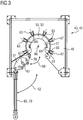
- FIG. 3 The plan view of the platform 49 of the securing device 45 show the Figures 3 and 4 , in which FIG. 3 the open to receive the rotor 13 platform 49 shows and FIG. 4 the closed platform 49 with centrally arranged tie rod 15 and front hollow shaft 22 according to the sectional view IV-IV of FIG. 2 ,
- a centrally disposed opening 51 is provided, in which an axial portion of the hollow shaft 22 can be inserted.
- the opening 51 is enclosed by a segmented ring 53, whose first segment 55 comprises a segmental arc of approximately 270 ° and whose second segment 57 comprises a segmental arc of approximately 90 °.
- the second ring segment 57 is pivotable relative to the first ring segment 55 about an axis of rotation 59, which serves for easy and quick closing and opening of the ring 53 (see. FIG. 4 ). Both segments 55, 57 each have an inwardly directed support surface 61, which can each be applied to a portion of the lateral surface of the rotor 13 and the tie rod 15.
- the ring 53 lies in a plane parallel to the horizontal plane 47, ie parallel to the foundation 29, and can be displaced by means of an auxiliary device supporting it within this plane for vertical alignment of the rotor 13.
- the Auxiliary device comprises, for example, a plurality of screw connections 63 fastened to the platform 49. Each of these screw connections 63 has a screw axis 67, which likewise lies in the plane parallel to the horizontal plane 47.
- the screw 63 are arranged radially with a closed ring 53, so that their screw axes 67 meet in a virtual center 66.
- screw 63 can also be provided in each case a hydraulic arrangement with a movable piston rod to laterally support the ring 53 and thereby align the rotor 13 (or tie rod 15) relative to the turn block 27 such that of this from an approximately vertical orientation in a vertical alignment can be shifted.
- the ring 53 may be mounted in a double-nested eccentric, so that the opening 51 relative to the axis 35 of the turning block 27 is arbitrarily alignable.
- the ring 53 is only optional.
- the lateral support of the rotor 13 it is also possible for the lateral support of the rotor 13 to take place directly from the screw connections 63 or directly from the piston rods of the hydraulic cylinders.
- the support surfaces 61 would then be arranged on the inwardly projecting free ends 69 of the screw 63 or the inwardly projecting free ends of the piston rods of the hydraulic cylinders, which would then be applied directly to the lateral surface of the rotor 13.
- the ring 53 and the platform 49 must first be opened.
- the second segment 57 of the ring 53 is pivotable about the rotation axis 59 according to the arrow 60 from a closed position to an open position (shown).
- FIG. 4 shows the top view of the securing device 45 with the almost completely closed ring 53.
- the ring 53 surrounds the hollow shaft 22 so that the support surfaces 61 abut the lateral surface of the hollow shaft 22.
- the ring 53 is displaceable over the individual screw 63 in the plane parallel to the foundation 29, so that the center of the ring 53 and thus the center of the tie rod 15 relative to the turn block 27 and thus relative to the central Rotorabstütztician is slightly displaced to the rotor thirteenth in a vertical orientation.
- the rotor 13 to be vertically aligned may comprise only the tie rod 15, which is secured against overturning by the support surfaces 61.
- the rotor 13 can also be understood to mean a tie rod 15 which is fully fitted with rotor disks 19, 21 and which is supported in an analogous manner.
- Tie rod 15 are aligned in the vertical, by the contact surfaces 61, at which the rotor 13, respectively, during alignment. the tie rod 15 is supported so displaced that it comes to stand perpendicular with respect to the horizontal plane.
Landscapes
- Engineering & Computer Science (AREA)
- Mechanical Engineering (AREA)
- General Engineering & Computer Science (AREA)
- Turbine Rotor Nozzle Sealing (AREA)
- Structures Of Non-Positive Displacement Pumps (AREA)
Description
- Die Erfindung betrifft eine Sicherungsvorrichtung zur Sicherung eines quer gegenüber einer Horizontalebene aufgestellten Rotors einer Strömungsmaschine gegen Umkippen, mit mindestens einer Abstützfläche, durch die ein zur Horizontalebene quer aufgestellter Rotor seitlich von der Sicherungsvorrichtung abstützbar ist. Des Weiteren betrifft die Erfindung ein Verfahren zum lotrechten Ausrichten eines senkrecht zur Horizontalebene aufzustellenden Rotors einer Strömungsmaschine.
- Gasturbinen sowie deren struktureller Aufbau sind allgemein bekannt. Die Rotoren von Gasturbinen können dabei in unterschiedlicher Art und Weise aufgebaut und zusammengesetzt sein. Eine Rotorvariante umfasst eine Vielzahl von aneinanderliegenden Elementen, welche über einen sich zentral durch die Elemente erstreckenden Zuganker verspannt sind. Diese Elemente sind einerseits Rotorscheiben und andererseits Rohrabschnitte, so genannte Hohlwellen, die an den Rotorscheiben anliegen können. Das Verspannen der Rotorscheiben und der Hohlwellen erfolgt mit jeweils endseitig auf dem Zuganker aufgeschraubten Schraubenmuttern, wobei häufig die verdichterseitig vorgesehene Schraubenmutter als Hohlwelle ausgebildet ist. Die stirnseitig flächig aneinander liegenden Rotorscheiben tragen in der Regel an ihren Außenumfängen die Laufschaufeln der Turbine und des Verdichters. Anstelle eines zentralen Zugankers ist es auch bekannt, mehrere dezentrale Zuganker zu verwenden.
- Um einen derartigen mehrteiligen Rotor zusammenzusetzen und zu zerlegen ist ein Montagewerkzeug bekannt, welches im Wesentlichen zwei Lagerböcke umfasst. Die beiden Lagerböcke werden zueinander beabstandet aufgestellt und der Rotor wird auf ihnen abgelegt. Einer der beiden Lagerböcke - der so genannte Wendebock - ist dabei mit einem zwischen Fuß und Auflagefläche angeordnetem Gelenk ausgestattet, welches mit einem Ende des Rotors befestigt wird. Der Rotor wird also so platziert, dass sein beispielsweise verdichterseitiges Ende unmittelbar an dem Gelenk des Wendebocks befestigt werden kann. Der andere Lagerbock stützt dann den Rotor turbinenseitig ab. Das am Wendebock befestigte Gelenk dient zur Umlagerung des Rotors aus der waagerechten Lage in eine dazu senkrechte Position. Dazu wird am turbinenseitigen Ende des Rotors eine Anhängemutter auf den Zuganker aufgeschraubt. An die Anhängemutter wird mittels eines Schäkels ein Seil eines Krans befestigt. Während der Kran das turbinenseitige Ende des Rotors anhebt, dreht sich das verdichterseitige Ende um den Drehpunkt des Gelenks. Der Anhebevorgang ist abgeschlossen, wenn der Rotor in einer annähernd senkrechten Position angelangt ist. Dann wird dieser mittels einer Sicherung, welche auch am Wendebock vorgesehen ist, gegen Umkippen gesichert. In der Regel umfasst diese Sicherung einen Blockierbolzen, der am Wendebock oberhalb des Gelenks vorgesehen ist und das Zurückbewegen des Rotors aus der Senkrechten blockiert. Anschließend wird die Anhängemutter demontiert, wonach dann die eigentlichen Arbeiten am senkrecht aufgestellten Rotor (oder Zuganker) erfolgen können.
- Für den Zusammenbau des Rotors wird zuerst der Zuganker senkrecht aufgestellt und anschließend die einzelnen Rotorscheiben mittels eines Krans nacheinander von Oben auf den Zuganker aufgefädelt. Anschließend wird eine turbinenseitige Rotormutter aufgeschraubt. Bei der Demontage eines vollständig montierten Rotors wird nach dessen senkrechter Aufstellung die turbinenseitig angeordnete Rotormutter entfernt, wonach die einzelnen Rotorscheiben mit Hilfe eines Krans dem Zuganker entnommen werden können. Der Rotor umfasst dann im Wesentlichen nur noch den Zuganker.
- Eine ähnliche Aufstellvorrichtung mit einem Wendebock ist aus der deutschen Offenlegungsschrift
24 26 231 bekannt. Zentral unter dem Wendebock ist am Fundament ein erster Anschlag befestigt. Im Unterschied zur vorgenannten Vorrichtung wird nicht das Ende des Rotors am Wendebock befestigt, sondern ein vom Ende beabstandeter Rotorpunkt. Beim Anheben des längeren Rotorabschnittes schwenkt dann der kürzere Rotorabschnitt zum Fundament hin. Der am kürzeren Rotorabschnitt angeordnete Kupplungsflansch liegt nach der senkrechter Aufstellung am ersten Anschlag an, wonach auf der anderen Seite des Flansches dann ein zweiter Anschlag angepasst und über Schrauben mit dem ersten Anschlag zur Sicherung des Rotors gegen Umkippen fest verbunden wird, - Aufgabe der vorliegenden Erfindung ist die Bereitstellung einer Sicherungsvorrichtung zur Sicherung eines quer gegenüber einer Horizontalebene aufgestellten Rotors oder Zugankers einer Strömungsmaschine, bei der der Rotor resp. Zuganker besonders einfach in die Lotrechte ausrichtbar ist. Weitere Aufgabe ist es, hierzu ein entsprechendes Verfahren anzugeben.
- Die erstgenannte Aufgabe wird durch eine Sicherungsvorrichtung mit den Merkmalen des Anspruchs 1 gelöst. Die auf das Verfahren gerichtete Aufgabe wird durch ein Verfahren gemäß den Merkmalen des Anspruchs 10 gelöst.
- Die Erfindung geht von der Erkenntnis aus, dass ein besonders einfaches Ausrichten des annähernd senkrecht gegenüber der Horizontalebene aufgestellten Rotors resp. Zugankers in die Lotrechte erreicht werden kann, wenn die mindestens eine Abstützfläche der Sicherungsvorrichtung, an welcher der Rotor bereits während des erfindungsgemäßen Ausrichtens anliegt, zumindest geringfügig verlagerbar ist. Insbesondere, wenn der Rotor schlussendlich in die Lotrechte ausgerichtet werden soll, sind die vom Rotor auf die Sicherungsvorrichtung quer zur Normalkraft einwirkenden Kräfte vergleichsweise gering, so dass die Sicherungsvorrichtung dementsprechend angepasst dimensioniert werden kann. Des Weiteren ermöglicht der lotrecht stehende Rotor eine besonders einfache Auf- bzw. Abfädelung von Rotorscheiben auf den Zuganker, ohne dass diese beim Anheben oder Absenken aufgrund einer Schiefstellung des Zugankers letztgenannten berühren.
- Sofern die Abstützfläche, an welcher sich der Rotor anlegt, in einer Ebene annähernd parallel zur Horizontalebene verlagerbar ist, kann der bereits schon annähernd senkrecht stehende Rotor so ausgerichtet werden, dass lediglich Balancekräfte von der Sicherungsvorrichtung aufgenommen werden müssen. Die Sicherungsvorrichtung muss dann keine Gewichtskraft oder nur sehr geringe Gewichtskräfte des Rotors aufnehmen. Zweckmäßiger Weise ist die Sicherungsvorrichtung Teil einer modularen Montagevorrichtung, welche neben der vorzugsweise als Gerüst ausgebildeten Sicherungsvorrichtung einen separat ausgebildeten Wendebock umfasst. Das erfindungsgemäße Verfahren ist dann zeitsparend mit einer erfindungsgemäßen Vorrichtung unter Erreichung der vorgenannten Vorteile durchführbar.
- Vorteilhafte Ausgestaltungen sind in den Unteransprüchen angegeben.
- In einer bevorzugten Ausgestaltung ist die Abstützfläche an einem sich aus mindestens zwei Ringsegmenten zusammensetzenden Ring angeordnet. Die Abstützfläche kann sich dabei an einem Teil der Mantelfläche des Rotors, insbesondere an der Mantelfläche einer Hohlwelle oder einer Rotorscheibe, anlegen. Vorzugsweise ist die Abstützfläche die innere zylindrische Fläche des Rings, wobei der an dem Rotor befestigte Ring auch als mechanischer Schutz vorgesehen sein kann. Der Ring kann entweder an dem noch in der waagerechten befindlichen Rotor befestigt werden, also noch vor dem Aufstellen des Rotors in die Senkrechte. Oder, der Ring ist in der gerüstartigen Sicherungsvorrichtung bereits vormontiert und so weit geöffnet, dass der Rotorabschnitt, welcher in den Ring eingelegt werden soll, einbringbar ist.
- Um den Rotor besonders einfach und schnell in einer Sicherungsvorrichtung zu befestigen, ist eines der beiden Ringsegmente gegenüber dem anderen Ringsegment schwenkbar befestigt. Hierdurch kann eine besonders einfach Montage des Rings am Rotor erfolgen, unabhängig davon, ob der Ring am waagerechten Rotor vormontiert wird oder ob der Ring an der Sicherungsvorrichtung vorab befestigt ist.
- Um die Abstützflächen zu verlagern, sind mehrere Verschraubungen oder mehrere Hydraulikzylinder vorgesehen, welche sich jeweils parallel oder nahezu parallel zur Horizontalebene erstrecken und welche parallel oder nahezu parallel zur Horizontalebene bewegbare Elemente wie Schrauben oder Hydraulikkolben aufweisen. Dabei sind mindestens drei Verschraubungen bzw. Hydraulikzylinder vorgesehen, um den annähernd senkrecht aufgestellten Rotor derartig zu verlagern, dass dieser aus einer annähernd senkrechten Position in die Lotrechte gebracht werden kann. Vorzugsweise sind jedoch mehr als drei, insbesondere vorzugsweise acht oder neun Verschraubungen bzw. Hydraulikzylinder vorgesehen, um eine besonders sichere seitliche Abstützung und um eine besonders exakte Ausrichtung zu gewährleisten. Dies ist insbesondere für Rotoren von schweren, zur kommerziellen Stromerzeugung genutzten Gasturbinen erforderlich, da deren Rotorgewicht mehrere zehntausend Kilogramm betragen kann.
- Die Verschraubungen oder Hydraulikzylinder der Sicherungsvorrichtung sind dabei strahlenartig um einen virtuellen Mittelpunkt angeordnet. Die Sicherungsvorrichtung und der Wendebock sind darüber hinaus derartig am Fundament gegeneinander auszurichten und zu befestigen, dass in der Senkrechten die Projektion des virtuellen Mittelpunkts mit einem zentralen Rotorabstützpunkt am Wendebock zusammenfällt. Der zentrale Rotorabstützpunkt ist dabei der auf der Drehachse des Gelenks liegende Punkt, auf dem der Schwerpunkt des Rotors platziert werden soll. Insbesondere hierdurch kann das lotrechte Ausrichten des Rotors vergleichsweise schnell erfolgen bei vergleichsweise geringem Aufwand.
- Anstelle von mehreren Verschraubungen oder mehreren Hydraulikzylindern kann in einer alternativen Ausgestaltung der Sicherungsvorrichtung mindestens eine Excenterscheibe vorgesehen sein, in welcher die Abstützfläche angeordnet ist. Damit mittels der Abstützfläche der annähernd senkrecht aufgestellte Rotor in jede beliebige Position gegenüber dem Rotorabstützpunkt des Wendebocks balanciert werden kann, sind vorzugsweise zwei ineinander geschachtelte Excenterscheiben vorgesehen, von denen die innere Excenterscheibe die Abstützfläche aufweist. Auch hierdurch ist eine besonders einfache Ausrichtung des annähernd senkrecht aufgestellten Rotors in die Lotrechte möglich.
- In einer vorteilhaften Ausgestaltung der Sicherungsvorrichtung weist diese oberhalb des Fundamentes eine auf mehreren Stützen und Streben aufgebockte Plattform oder Arbeitsbühne auf. Die Plattform kann beispielsweise als Arbeitsplattform für Monteure dienen, welche die Ausrichtung des Rotors in die Lotrechte vornehmen. Insbesondere dann ist es von Vorteil, wenn die Abstützfläche auf der Höhe der Plattform, beispielsweise in dessen Boden, vorgesehen ist. Die eine oder mehrere Abstützflächen können dann mit der Plattform über die Verschraubungen oder der Hydraulikzylinder verbunden sein. Vorzugsweise beträgt der Abstand zwischen dem Gelenk des Wendebocks und der darüber angeordneten Abstützfläche ca. 2 - 3 m.
- Die Erfindung wird anhand einer Zeichnung erläutert. Es zeigen schematisch und in nicht maßstäblicher Weise:
- FIG 1
- die Montagevorrichtung zum Zusammensetzen und Zerlegen eines Rotors mit parallel zur Horizontal-ebene (waagerecht) angeordnetem Rotor,
- FIG 2
- die Montagevorrichtung gemäß
FIG 1 mit senkrecht aufgestelltem Rotor, - FIG 3
- die Draufsicht auf die Sicherungsvorrichtung bei geöffneter Aufnahme und
- FIG 4
- die Draufsicht auf die Sicherungsvorrichtung mit eingelegtem Rotor.
- In den Figuren sind identische Bauteile mit gleichen Bezugszeichen versehen.
- In
FIG 1 ist ein auf zwei Lagerböcken 11 abgelegter Rotor 13 einer schweren stationären Gasturbine dargestellt. Der Rotor 13 umfasst einen Zuganker 15, der sich zentral durch eine Vielzahl von Turbinenscheiben 17 und Verdichterscheiben 19 erstreckt. Im dargestellten Beispiel ist das verdichterseitige Ende des Rotors 13 links dargestellt. Die Turbinenscheiben 17 und die Verdichterscheiben 19 sind Rotorscheiben 21 und tragen an ihren äußeren Enden Laufschaufeln, die einem kompressiblen Strömungsmedium der Gasturbine aussetzbar sind. - Zum Verspannen der Rotorscheiben 21 ist am verdichterseitigen Ende 33 des Rotors 13 eine vordere Hohlwelle 22 auf den Zuganker 15 aufgeschraubt. Turbinenseitig ist eine Schraubenmutter 24 vorgesehen.
- Um den modularen Rotor 13 der Gasturbine in seine Einzelteile zu zerlegen, oder um auf einen Zuganker 15 Rotorscheiben 19, 21 aufzufädeln, ist neben den beiden Lagerböcken 11 eine Montagevorrichtung 23 vorgesehen, welche rotorendseitig angeordnet ist. Die Montagevorrichtung 23 umfasst einen Wendebock 27, der auf einem Fundament 29 befestigt ist. Der Wendebock 27 ist zu den beiden Lagerböcken 11 fluchtend aufgestellt und weist dabei an seiner Spitze ein Gelenk 31 auf, welches mit dem verdichterseitigen Ende 33 des Rotors 13 verbunden ist. Der Rotor 13 ist dabei um eine zur Horizontalebene 47 parallele Drehachse des Gelenks 31 drehbar. Ferner umfasst das Gelenk 31 eine wälzgelagerte Aufnahme für einen um eine senkrechte Achse 35 drehbaren Drehteller 37. Auf der senkrechten Achse 35 liegt außerdem der Rotorabstützpunkt.
- Am turbinenseitigen Ende 39 des Rotors 13 ist eine Anhängemutter 41 montiert, an der mittels eines Schäkels das Seil eines Krans angeschlagen werden kann.
- Die Montagevorrichtung 23 umfasst des Weiteren eine als Gerüst 43 ausgebildete Sicherungsvorrichtung 45, welche vom Wendebock 27 getrennt im Fundament 29 verankert ist.
- Das Gerüst 43 umfasst eine auf vier senkrechten Stützen 64 aufgebockte Plattform 49 oder Arbeitsbühne. Zur Versteifung des Gerüsts 43 sind an jeder Seitenkante des Gerüsts 43 weitere sich quer zu den Stützen 64 erstreckende Streben 65 vorgesehen, die die fundamentseitigen Enden der Stützen 64 mit der Plattform 49 zusätzlich verbinden.
- Damit der Rotor 13 in das Gerüst 43 und in die Sicherungsvorrichtung 45 eingeschwenkt werden kann, kann ein Teil der Plattform 49 und die darunter angeordneten Streben 65 aus dem Schwenkbereich des Rotors 13 herausbewegt werden. Die Plattform 49 und die Sicherungsvorrichtung 45 weisen dann eine geöffnete Aufnahme auf (vgl.
FIG 3 ). - Durch das Anheben des turbinenseitigen Endes 39 des Rotors 13 mit dem Kran wird der Rotor 13 aus den beiden Lagerböcken 11 gehoben, wobei das verdichterseitige Ende des Rotors 13 sich um die Drehachse des Gelenks 31 dreht. Bei geöffneter Aufnahme kann dann der Rotor 13 aus seiner horizontalen Lage (
FIG 1 ) in die vertikale Lage (FIG 2 ) gewendet werden, wonach dieser mittels der Sicherungsvorrichtung 45 gegen Umkippen gesichert wird. Hierzu wird die Aufnahme geschlossen. Anschließend befindet sich der Rotor 13 in der inFIG 2 gestellten Lage. - Die gesamte Gewichtskraft des bei stationären Gasturbinen vergleichsweise schweren Rotors 13 lastet dann auf dem Wendebock 27, wohingegen das Gerüst 43 das Umkippen des Rotors 13 mit vergleichsweise geringen Kräften verhindern kann. Die geringste Kraft ist erforderlich, wenn der Rotor 13 lotrecht ausgerichtet ist und die Symmetrieachse 46 des Rotors 13 mit der Achse 35 des Drehtellers 37 übereinstimmt.
- Aufgrund des vergleichsweise großen Abstands zwischen Gelenk 31 und der seitlichen Abstützung des Rotors 13 auf Höhe der Plattform 49 kann eine besonders zuverlässige und zudem auch erdbebensichere seitliche Abstützung des Rotors 13 angegeben werden. Erdbebensicher heißt in diesem Umfang, dass die bei vergleichsweise schwachen Erdbeben mit einer vergleichsweise geringen Stärke auftretenden Beschleunigungskräfte auf den Rotor 13 in der Größenordnung von ca. ½ g (1g = einfache Erdbeschleunigung) von der Sicherungsvorrichtung 45 aufgefangen und über die Plattform 49 und die Streben 65 ins Fundament 29 abgeleitet werden können.
- Die Draufsicht auf die Plattform 49 der Sicherungsvorrichtung 45 zeigen die
Figuren 3 und4 , wobeiFIG 3 die zur Aufnahme des Rotors 13 geöffnete Plattform 49 zeigt undFIG 4 die verschlossene Plattform 49 mit zentral angeordnetem Zuganker 15 und vorderer Hohlwelle 22 gemäß der Schnittansicht IV-IV derFIG 2 . In der Plattform 49 der Sicherungsvorrichtung 45 ist eine zentral angeordnete Öffnung 51 vorgesehen, in welcher ein axialer Abschnitt der Hohlwelle 22 eingelegt werden kann. Die Öffnung 51 wird von einem segmentierten Ring 53 umschlossen, dessen erstes Segment 55 einen Segmentbogen von ungefähr 270° und dessen zweites Segment 57 einen Segmentbogen von ca. 90° umfasst. Das zweite Ringsegment 57 ist gegenüber dem ersten Ringsegment 55 um eine Drehachse 59 verschwenkbar, was zum einfachen und schnellen Schließen und Öffnen des Rings 53 dient (vgl.FIG 4 ). Beide Segmente 55, 57 weisen je eine nach innen gerichtete Abstützfläche 61 auf, die jeweils an einem Abschnitt der Mantelfläche des Rotors 13 bzw. des Zugankers 15 anlegbar ist. - Der Ring 53 liegt in einer Ebene parallel zur Horizontalebene 47, also parallel zum Fundament 29, und kann mittels einer ihn tragenden Hilfsvorrichtung innerhalb dieser Ebene zur lotrechten Ausrichtung des Rotors 13 verlagert werden. Die Hilfsvorrichtung umfasst beispielsweise mehrere an der Plattform 49 befestigte Verschraubungen 63. Jede dieser Verschraubung 63 weist eine Schraubenachse 67 auf, die ebenfalls in der Ebene parallel zur Horizontalebene 47 liegt. Die Verschraubungen 63 sind bei geschlossenem Ring 53 strahlenförmig angeordnet, so dass sich deren Schraubenachsen 67 in einem virtuellen Mittelpunkt 66 treffen. Anstelle der Verschraubungen 63 kann auch jeweils eine Hydraulikanordnung mit bewegbaren Kolbenstange vorgesehen sein, um den Ring 53 seinerseits seitlich abzustützen und dabei den Rotor 13 (oder auch Zuganker 15) gegenüber dem Wendebock 27 derart auszurichten, dass von dieser von einer annähernd senkrechten Ausrichtung in eine lotrechte Ausrichtung verlagert werden kann.
- Anstelle der Verschraubung oder anstelle von Hydraulikzylindern kann auch der Ring 53 in einem zweifach geschachtelten Excenter gelagert sein, so dass die Öffnung 51 gegenüber der Achse 35 des Wendebocks 27 beliebig ausrichtbar ist.
- Auch der Ring 53 ist insgesamt nur optional. Es ist beispielsweise auch möglich, dass die seitliche Abstützung des Rotors 13 unmittelbar von den Verschraubungen 63 oder unmittelbar von den Kolbenstangen der Hydraulikzylinder erfolgt. Die Abstützflächen 61 wären dann an den nach innen ragenden freien Enden 69 der Verschraubungen 63 oder den nach innen ragenden freien Enden der Kolbenstangen der Hydraulikzylindern angeordnet, welche dann unmittelbar an die Mantelfläche des Rotors 13 anlegbar wären.
- Damit der Rotor 13 beim Anheben seines turbinenseitigen Endes 39 in die Öffnung 51 eingeschwenkt werden kann, ist der Ring 53 und die Plattform 49 zuvor zu öffnen. Hierzu ist vorgesehen, dass das zweite Segment 57 des Rings 53 um die Drehachse 59 gemäß dem Pfeil 60 von einer geschlossenen Position in eine offene Position (dargestellt) schwenkbar ist. In gleicher Art und Weise sind die in der
FIG 3 unten dargestellten Streben 65 und das Geländer 70 der Arbeitsbühne von der Plattform 49 gemäß dem Pfeil 62 weggeklappt, so dass insgesamt die Aufnahme geöffnet ist. -
FIG 4 zeigt die Draufsicht auf die Sicherungsvorrichtung 45 mit dem annähernd vollständig geschlossenen Ring 53. Der Ring 53 umgreift die Hohlwelle 22, so dass die Abstützflächen 61 an der Mantelfläche der Hohlwelle 22 anliegen. Der Ring 53 ist über die einzelnen Verschraubungen 63 in der Ebene parallel zum Fundament 29 verschiebbar, so dass der Mittelpunkt des Rings 53 und somit der Mittelpunkt des Zugankers 15 gegenüber dem Wendebock 27 und somit gegenüber dem zentralen Rotorabstützpunkt geringfügig verlagerbar ist, um den Rotor 13 in eine lotrechte Ausrichtung zu bringen. - Im Sinne der Erfindung kann der lotrecht auszurichtende Rotor 13 einerseits nur den Zuganker 15 umfassen, welcher von den Abstützflächen 61 gegen Umkippen gesichert ist. Andererseits kann unter dem Rotor 13 auch ein mit Rotorscheiben 19, 21 vollständig bestückter Zuganker 15 verstanden werden, der in analoger Weise abgestützt ist.
- Für ein besonders einfaches Auf- und Abfädeln von Rotorscheiben 19, 21 auf den Zuganker 15, bei dem ein die Bauteile ggf. schädigender Kontakt zwischen den Rotorscheiben 19, 21 und dem Zuganker 15 beim Absenken oder Anheben der Rotorscheiben 19, 21 vermieden werden soll, kann insgesamt ein annähernd senkrecht aufgestellter Rotor 13 resp. Zuganker 15 in die Lotrechte ausgerichtet werden, indem während des Ausrichtens die Anlageflächen 61, an welchen sich der Rotor 13 resp. der Zuganker 15 abstützt, so verlagert werden, dass dieser senkrecht in Bezug auf die Horizontalebene zu stehen kommt.
Claims (10)
- Sicherungsvorrichtung (45) zur Sicherung eines quer gegenüber einer Horizontalebene (47) aufgestellten Rotors (13) einer Strömungsmaschine gegen Umkippen,
mit mindestens einer Abstützfläche (61), durch die ein zur Horizontalebene (47) quer aufgestellter Rotor (13) seitlich von der Sicherungsvorrichtung (45) abstützbar ist, dadurch gekennzeichnet, dass
zum lotrechten Ausrichten des Rotors (13) die Abstützfläche (61), an welcher ein annähernd senkrecht aufgestellter Rotor während des Ausrichtens anliegt, parallel zur Horizontalebene (47) geringfügig verlagerbar ist. - Sicherungsvorrichtung (45) nach Anspruch 1,
bei der die Abstützfläche (61) an einem sich aus mindestens zwei Ringsegmenten (55, 57) zusammensetzenden Ring (53) angeordnet ist. - Sicherungsvorrichtung (45) nach Anspruch 2,
bei der eines der beiden Ringsegmente (57) gegenüber dem anderen Ringsegment (55) schwenkbar befestigt ist. - Sicherungsvorrichtung (45) nach Anspruch 1 bis 3,
bei der mehrere Verschraubungen (63) oder mehrere Hydraulikzylinder vorgesehen sind, welche sich jeweils parallel zur Horizontalebene (47) erstrecken und welche parallel zur Horizontalebene (47) bewegbare Elemente zur Verlagerung der Abstützfläche (61) aufweisen. - Sicherungsvorrichtung (45) nach Anspruch 4,
bei der die Verschraubungen (63) oder Hydraulikzylinder strahlenartig um einen virtuellen Mittelpunkt (66) angeordnet sind. - Sicherungsvorrichtung (45) nach Anspruch 1 bis 3,
die mindestens eine Excenterscheibe umfasst, in welcher die Abstützfläche (61) vorgesehen ist. - Sicherungsvorrichtung (45) nach einem der Ansprüche 1 bis 6,
die auf einem Fundament (29) befestigbar ist und eine am Fundament (29) mittels mehrerer Stützen (64) und Streben (65) aufgebockte Plattform (49) aufweist. - Sicherungsvorrichtung (45) nach Anspruch 7,
bei der die Abstützfläche (61) auf der Höhe der Plattform vorgesehen ist. - Montagevorrichtung (23) zum Zusammensetzen und Zerlegen eines sich aus Rotorscheiben (21) zusammensetzenden Rotors (13) einer Strömungsmaschine,
welche Rotorscheiben (21) von mindestens einem Zuganker (15) miteinander verspannt sind,
umfassend:ein auf einem Fundament (29) befestigten Wendebock (27) und eine Sicherungsvorrichtung (45) nach einem der Ansprüche 1 bis 8 zur Sicherung eines am Wendebock (27) schwenkbar lagerbaren und gegenüber einer Horizontalebene (47) des Fundaments (29) quer aufstellbaren Rotors (13) gegen Umkippen,dadurch gekennzeichnet,
dass die Sicherungsvorrichtung (45) vom Wendebock (27) getrennt über Stützen am Fundament (29) befestigbar ist. - Verfahren zum lotrechten Ausrichten eines senkrecht zur Horizontalebene aufzustellenden Rotors (13) oder dessen Zugankers (15) einer Strömungsmaschine,
bei dem der bereits annähernd senkrecht aufgestellte Rotor (13) respektive Zuganker (15) von an einer Sicherungsvorrichtung (45) oder Montagevorrichtung (23) angeordneten Abstützfläche (61) abgestützt ist,
dadurch gekennzeichnet, dass
nach dem Aufstellen des Rotors (13) respektive Zuganker (15) in eine annähernd Senkrechte dieser durch eine Verlagerung der ihn bereits seitlich abstützenden Abstützflächen (61) in die Lotrechte ausgerichtet wird.
Priority Applications (1)
| Application Number | Priority Date | Filing Date | Title |
|---|---|---|---|
| EP08735741.4A EP2134927B1 (de) | 2007-04-16 | 2008-04-03 | Sicherungsvorrichtung zur sicherung eines quer gegenüber einer horizontalebene aufgestellten rotors einer strömungsmaschine gegen umkippen sowie ausrichtverfahren dazu |
Applications Claiming Priority (3)
| Application Number | Priority Date | Filing Date | Title |
|---|---|---|---|
| EP20070007681 EP1983161A1 (de) | 2007-04-16 | 2007-04-16 | Sicherungsvorrichtung zur Sicherung eines quer gegenüber einer Horizontalebene aufgestellten Rotors einer Strömungsmaschine gegen Umkippen sowie Montagevorrichtung |
| PCT/EP2008/053992 WO2008125506A1 (de) | 2007-04-16 | 2008-04-03 | Sicherungsvorrichtung zur sicherung eines quer gegenüber einer horizontalebene aufgestellten rotors einer strömungsmaschine gegen umkippen sowie ausrichtverfahren dazu |
| EP08735741.4A EP2134927B1 (de) | 2007-04-16 | 2008-04-03 | Sicherungsvorrichtung zur sicherung eines quer gegenüber einer horizontalebene aufgestellten rotors einer strömungsmaschine gegen umkippen sowie ausrichtverfahren dazu |
Publications (2)
| Publication Number | Publication Date |
|---|---|
| EP2134927A1 EP2134927A1 (de) | 2009-12-23 |
| EP2134927B1 true EP2134927B1 (de) | 2017-03-08 |
Family
ID=38436746
Family Applications (3)
| Application Number | Title | Priority Date | Filing Date |
|---|---|---|---|
| EP20070007681 Withdrawn EP1983161A1 (de) | 2007-04-16 | 2007-04-16 | Sicherungsvorrichtung zur Sicherung eines quer gegenüber einer Horizontalebene aufgestellten Rotors einer Strömungsmaschine gegen Umkippen sowie Montagevorrichtung |
| EP20080735742 Active EP2134928B1 (de) | 2007-04-16 | 2008-04-03 | Montagevorrichtung zum zusammensetzen und zerlegen eines sich aus rotorscheiben zusammensetzenden rotors einer strömungsmaschine |
| EP08735741.4A Not-in-force EP2134927B1 (de) | 2007-04-16 | 2008-04-03 | Sicherungsvorrichtung zur sicherung eines quer gegenüber einer horizontalebene aufgestellten rotors einer strömungsmaschine gegen umkippen sowie ausrichtverfahren dazu |
Family Applications Before (2)
| Application Number | Title | Priority Date | Filing Date |
|---|---|---|---|
| EP20070007681 Withdrawn EP1983161A1 (de) | 2007-04-16 | 2007-04-16 | Sicherungsvorrichtung zur Sicherung eines quer gegenüber einer Horizontalebene aufgestellten Rotors einer Strömungsmaschine gegen Umkippen sowie Montagevorrichtung |
| EP20080735742 Active EP2134928B1 (de) | 2007-04-16 | 2008-04-03 | Montagevorrichtung zum zusammensetzen und zerlegen eines sich aus rotorscheiben zusammensetzenden rotors einer strömungsmaschine |
Country Status (7)
| Country | Link |
|---|---|
| US (2) | US9003656B2 (de) |
| EP (3) | EP1983161A1 (de) |
| JP (2) | JP4948644B2 (de) |
| AT (1) | ATE510998T1 (de) |
| ES (1) | ES2365375T3 (de) |
| PL (1) | PL2134928T3 (de) |
| WO (2) | WO2008125507A1 (de) |
Families Citing this family (9)
| Publication number | Priority date | Publication date | Assignee | Title |
|---|---|---|---|---|
| GB201005351D0 (en) * | 2010-03-30 | 2010-05-12 | Rolls Royce Plc | Support frame |
| EP2570621A1 (de) | 2011-09-15 | 2013-03-20 | Siemens Aktiengesellschaft | Vorrichtung zum Schwenken eines Rotors einer Strömungsmaschine aus einer ersten Lage in eine zweite Lage |
| DK2667493T3 (da) * | 2012-05-21 | 2020-02-24 | Siemens Gamesa Renewable Energy As | Fremgangsmåde til vertikal samling af en generator af en vindmølle |
| DE102014200760A1 (de) * | 2014-01-17 | 2015-07-23 | Siemens Aktiengesellschaft | Läuferschwenksystem |
| KR101926288B1 (ko) * | 2014-11-19 | 2018-12-06 | 미츠비시 히타치 파워 시스템즈 가부시키가이샤 | 가스 터빈의 유지보수 방법 |
| KR101871061B1 (ko) | 2016-11-17 | 2018-06-25 | 두산중공업 주식회사 | 가스 터빈 및 상기 가스 터빈의 베어링 교체 방법 |
| EP3647537A1 (de) * | 2018-10-30 | 2020-05-06 | Siemens Aktiengesellschaft | Sicherheitsvorrichtung zum eindämmen einer energiefreisetzung in einem zuganker einer rotoren-anordnung und zugehöriges verfahren |
| EP3647538A1 (de) | 2018-10-30 | 2020-05-06 | Siemens Aktiengesellschaft | Sicherheitsvorrichtung zum eindämmen einer energiefreisetzung einer rotoren-anordnung |
| JP7274942B2 (ja) * | 2019-05-31 | 2023-05-17 | 三菱重工業株式会社 | ロータ組立方法、ロータディスク保持治具及びロータスタンド |
Family Cites Families (17)
| Publication number | Priority date | Publication date | Assignee | Title |
|---|---|---|---|---|
| US2930492A (en) * | 1957-07-23 | 1960-03-29 | Orenda Engines Ltd | Work stand and loading apparatus |
| DE2026254A1 (en) * | 1969-06-23 | 1971-01-07 | VEB Bergmann Borsig/Gorhtzer Ma schinenbau, χ 1000 Berlin Wilhelmsruh | Welding device with pivotal stand for fluid - flow engine armatures |
| GB1409902A (en) * | 1972-05-24 | 1975-10-15 | Rolls Royce | Stationary gas turbine power plant mounting apparatus |
| JPS5072734A (de) | 1973-10-30 | 1975-06-16 | ||
| JPS51134107A (en) * | 1975-05-16 | 1976-11-20 | Matsushita Electric Ind Co Ltd | Recording stylus |
| DE3118073A1 (de) * | 1981-05-07 | 1982-11-25 | Hoechst Ag, 6000 Frankfurt | Diphenylaether-azoverbindungen, verfahren zu ihrer herstellung und ihre verwendung als farbstoffe |
| JPS6044267A (ja) | 1983-08-20 | 1985-03-09 | Toyota Motor Corp | 溶射層の密着性向上方法 |
| JPS61161823A (ja) * | 1985-01-10 | 1986-07-22 | Nec Corp | 入力回路 |
| JPH0721261B2 (ja) * | 1986-10-13 | 1995-03-08 | 三機工業株式会社 | ポ−ル垂直建方調整治具 |
| JPH0227071A (ja) * | 1988-07-18 | 1990-01-29 | Sanki Eng Co Ltd | ポール垂直建方調整治具 |
| JPH0572734A (ja) | 1991-09-11 | 1993-03-26 | Mitsubishi Petrochem Co Ltd | 感光性樹脂組成物 |
| JPH0882117A (ja) * | 1994-09-09 | 1996-03-26 | Masahito Kajii | 可倒ポール装置 |
| JP2780736B2 (ja) * | 1995-02-13 | 1998-07-30 | 山崎 勝己 | ポール支持装置 |
| JPH11323962A (ja) * | 1998-05-13 | 1999-11-26 | Kohan Kenzai Kk | 建付け調整具及び同建付け調整具を用いた建付け方法 |
| US6279309B1 (en) * | 1998-09-24 | 2001-08-28 | Ramgen Power Systems, Inc. | Modular multi-part rail mounted engine assembly |
| JP2001234646A (ja) * | 2000-02-24 | 2001-08-31 | Kyouyou:Kk | 鉄塔とこの鉄塔の形成方法 |
| JP5072734B2 (ja) | 2008-06-26 | 2012-11-14 | 三菱電機株式会社 | 永久磁石型回転電機およびパワーステアリング装置 |
-
2007
- 2007-04-16 EP EP20070007681 patent/EP1983161A1/de not_active Withdrawn
-
2008
- 2008-04-03 EP EP20080735742 patent/EP2134928B1/de active Active
- 2008-04-03 ES ES08735742T patent/ES2365375T3/es active Active
- 2008-04-03 PL PL08735742T patent/PL2134928T3/pl unknown
- 2008-04-03 WO PCT/EP2008/053993 patent/WO2008125507A1/de not_active Ceased
- 2008-04-03 JP JP2010503449A patent/JP4948644B2/ja not_active Expired - Fee Related
- 2008-04-03 JP JP2010503450A patent/JP4937408B2/ja not_active Expired - Fee Related
- 2008-04-03 AT AT08735742T patent/ATE510998T1/de active
- 2008-04-03 US US12/596,215 patent/US9003656B2/en not_active Expired - Fee Related
- 2008-04-03 EP EP08735741.4A patent/EP2134927B1/de not_active Not-in-force
- 2008-04-03 US US12/595,556 patent/US8667678B2/en not_active Expired - Fee Related
- 2008-04-03 WO PCT/EP2008/053992 patent/WO2008125506A1/de not_active Ceased
Non-Patent Citations (1)
| Title |
|---|
| None * |
Also Published As
| Publication number | Publication date |
|---|---|
| US20100107385A1 (en) | 2010-05-06 |
| ATE510998T1 (de) | 2011-06-15 |
| US20100139064A1 (en) | 2010-06-10 |
| EP2134927A1 (de) | 2009-12-23 |
| PL2134928T3 (pl) | 2011-10-31 |
| JP2010523901A (ja) | 2010-07-15 |
| WO2008125507A1 (de) | 2008-10-23 |
| JP2010523900A (ja) | 2010-07-15 |
| JP4937408B2 (ja) | 2012-05-23 |
| US9003656B2 (en) | 2015-04-14 |
| US8667678B2 (en) | 2014-03-11 |
| EP2134928B1 (de) | 2011-05-25 |
| WO2008125506A1 (de) | 2008-10-23 |
| JP4948644B2 (ja) | 2012-06-06 |
| EP1983161A1 (de) | 2008-10-22 |
| ES2365375T3 (es) | 2011-10-03 |
| EP2134928A1 (de) | 2009-12-23 |
Similar Documents
| Publication | Publication Date | Title |
|---|---|---|
| EP2134928B1 (de) | Montagevorrichtung zum zusammensetzen und zerlegen eines sich aus rotorscheiben zusammensetzenden rotors einer strömungsmaschine | |
| EP2798163B1 (de) | Verfahren zum ziehen und/oder einsetzen eines turbinenlagers sowie vorrichtung zur durchführung des verfahrens | |
| EP2742213B1 (de) | Vorrichtung zum schwenken eines rotors einer strömungsmaschine aus einer ersten lage in eine zweite lage | |
| EP1825141B1 (de) | Windenergieanlage mit halteeinrichtung für eine rotorwelle | |
| EP2423149B1 (de) | Rüsten eines Hilfshubwerks an einem Mobilkran | |
| DE3750572T2 (de) | Modulares gerüstsystem und verbindungselemente dafür. | |
| EP2278128A2 (de) | Gasturbine mit Abgasgehäuse sowie Verfahren zum Herstellen einer solchen Gasturbine | |
| WO2016078926A1 (de) | Gasturbine mit hebevorrichtung | |
| EP3538745B1 (de) | Verfahren zur montage und/oder demontage von komponenten einer ein turbinengehäuse aufweisenden turbine sowie adapter und system zur verwendung in dem verfahren | |
| EP2978942B1 (de) | Kragträgerschlitten für montage und demontage eines rotorblocks | |
| DE3934783A1 (de) | Kran und verfahren fuer dessen verwendung | |
| EP3208404B1 (de) | Verfahren und vorrichtung zur montage eines rohrturmsegments | |
| EP4230565B1 (de) | Auslösevorrichtung für eine hebekippvorrichtung zum lösen der hebekippvorrichtung von einem generatorsegment, hebekippvorrichtung zum heben und kippen eines generatorsegments, verfahren zum heben und kippen eines generatorsegments, und verfahren zur montage einer hebekippvorrichtung an einem demontierten generatorsegment | |
| DE10321850A1 (de) | Montagehilfe zum Errichten von Tragmasten von Windenergieanlagen | |
| EP0369938B1 (de) | Verfahren und Vorrichtung zur Demolierung von Mauerwerken | |
| EP4707587A2 (de) | Verfahren zur errichtung des turmbauwerks, und system zur handhabung von bauteilen eines turmbauwerks | |
| DE3633582C2 (de) | ||
| DE10308239A1 (de) | Verfahren und Vorrichtung zur Errichtung einer Windenergieanlage | |
| WO2000004255A1 (de) | Vorrichtung zum abbrechen eines eine umlaufende wandung aufweisenden bauwerks wie einem schornstein oder einem kühlturm | |
| EP3622164B1 (de) | Aufhängungssystem für eine gasturbine und zugehörige gasturbine | |
| DE202022105371U1 (de) | Hubvorrichtung für ein Ringsegment, Anordnung mit einer solchen Hubvorrichtung, und Anwendung der Hubvorrichtung | |
| WO2017045867A1 (de) | Türkonstruktion für ein rohrturmbauwerk | |
| EP3581794A1 (de) | Montagesystem und montageverfahren für einen rotorstern einer windenergieanlage | |
| EP3663574A1 (de) | Transportvorrichtung für eine rotornabe einer windenergieanlage | |
| DE102020112526B4 (de) | Vorrichtung und Verfahren zur Abspannung, Fliegendmontage und Rückrüstung eines Gitterauslegers |
Legal Events
| Date | Code | Title | Description |
|---|---|---|---|
| PUAI | Public reference made under article 153(3) epc to a published international application that has entered the european phase |
Free format text: ORIGINAL CODE: 0009012 |
|
| 17P | Request for examination filed |
Effective date: 20090909 |
|
| AK | Designated contracting states |
Kind code of ref document: A1 Designated state(s): AT BE BG CH CY CZ DE DK EE ES FI FR GB GR HR HU IE IS IT LI LT LU LV MC MT NL NO PL PT RO SE SI SK TR |
|
| DAX | Request for extension of the european patent (deleted) | ||
| RAP1 | Party data changed (applicant data changed or rights of an application transferred) |
Owner name: SIEMENS AKTIENGESELLSCHAFT |
|
| GRAP | Despatch of communication of intention to grant a patent |
Free format text: ORIGINAL CODE: EPIDOSNIGR1 |
|
| INTG | Intention to grant announced |
Effective date: 20161005 |
|
| GRAS | Grant fee paid |
Free format text: ORIGINAL CODE: EPIDOSNIGR3 |
|
| GRAA | (expected) grant |
Free format text: ORIGINAL CODE: 0009210 |
|
| AK | Designated contracting states |
Kind code of ref document: B1 Designated state(s): AT BE BG CH CY CZ DE DK EE ES FI FR GB GR HR HU IE IS IT LI LT LU LV MC MT NL NO PL PT RO SE SI SK TR |
|
| REG | Reference to a national code |
Ref country code: GB Ref legal event code: FG4D Free format text: NOT ENGLISH |
|
| REG | Reference to a national code |
Ref country code: CH Ref legal event code: EP Ref country code: AT Ref legal event code: REF Ref document number: 873720 Country of ref document: AT Kind code of ref document: T Effective date: 20170315 |
|
| REG | Reference to a national code |
Ref country code: IE Ref legal event code: FG4D Free format text: LANGUAGE OF EP DOCUMENT: GERMAN |
|
| REG | Reference to a national code |
Ref country code: DE Ref legal event code: R096 Ref document number: 502008015100 Country of ref document: DE |
|
| REG | Reference to a national code |
Ref country code: LT Ref legal event code: MG4D |
|
| REG | Reference to a national code |
Ref country code: NL Ref legal event code: MP Effective date: 20170308 |
|
| PG25 | Lapsed in a contracting state [announced via postgrant information from national office to epo] |
Ref country code: NO Free format text: LAPSE BECAUSE OF FAILURE TO SUBMIT A TRANSLATION OF THE DESCRIPTION OR TO PAY THE FEE WITHIN THE PRESCRIBED TIME-LIMIT Effective date: 20170608 Ref country code: GR Free format text: LAPSE BECAUSE OF FAILURE TO SUBMIT A TRANSLATION OF THE DESCRIPTION OR TO PAY THE FEE WITHIN THE PRESCRIBED TIME-LIMIT Effective date: 20170609 Ref country code: FI Free format text: LAPSE BECAUSE OF FAILURE TO SUBMIT A TRANSLATION OF THE DESCRIPTION OR TO PAY THE FEE WITHIN THE PRESCRIBED TIME-LIMIT Effective date: 20170308 Ref country code: HR Free format text: LAPSE BECAUSE OF FAILURE TO SUBMIT A TRANSLATION OF THE DESCRIPTION OR TO PAY THE FEE WITHIN THE PRESCRIBED TIME-LIMIT Effective date: 20170308 Ref country code: LT Free format text: LAPSE BECAUSE OF FAILURE TO SUBMIT A TRANSLATION OF THE DESCRIPTION OR TO PAY THE FEE WITHIN THE PRESCRIBED TIME-LIMIT Effective date: 20170308 |
|
| PGFP | Annual fee paid to national office [announced via postgrant information from national office to epo] |
Ref country code: DE Payment date: 20170619 Year of fee payment: 10 |
|
| RAP2 | Party data changed (patent owner data changed or rights of a patent transferred) |
Owner name: SIEMENS AKTIENGESELLSCHAFT |
|
| PG25 | Lapsed in a contracting state [announced via postgrant information from national office to epo] |
Ref country code: LV Free format text: LAPSE BECAUSE OF FAILURE TO SUBMIT A TRANSLATION OF THE DESCRIPTION OR TO PAY THE FEE WITHIN THE PRESCRIBED TIME-LIMIT Effective date: 20170308 Ref country code: ES Free format text: LAPSE BECAUSE OF FAILURE TO SUBMIT A TRANSLATION OF THE DESCRIPTION OR TO PAY THE FEE WITHIN THE PRESCRIBED TIME-LIMIT Effective date: 20170308 Ref country code: BG Free format text: LAPSE BECAUSE OF FAILURE TO SUBMIT A TRANSLATION OF THE DESCRIPTION OR TO PAY THE FEE WITHIN THE PRESCRIBED TIME-LIMIT Effective date: 20170608 Ref country code: SE Free format text: LAPSE BECAUSE OF FAILURE TO SUBMIT A TRANSLATION OF THE DESCRIPTION OR TO PAY THE FEE WITHIN THE PRESCRIBED TIME-LIMIT Effective date: 20170308 |
|
| PG25 | Lapsed in a contracting state [announced via postgrant information from national office to epo] |
Ref country code: NL Free format text: LAPSE BECAUSE OF FAILURE TO SUBMIT A TRANSLATION OF THE DESCRIPTION OR TO PAY THE FEE WITHIN THE PRESCRIBED TIME-LIMIT Effective date: 20170308 |
|
| REG | Reference to a national code |
Ref country code: CH Ref legal event code: NV Representative=s name: SIEMENS SCHWEIZ AG, CH Ref country code: CH Ref legal event code: PCOW Free format text: NEW ADDRESS: WERNER-VON-SIEMENS-STRASSE 1, 80333 MUENCHEN (DE) |
|
| PG25 | Lapsed in a contracting state [announced via postgrant information from national office to epo] |
Ref country code: CZ Free format text: LAPSE BECAUSE OF FAILURE TO SUBMIT A TRANSLATION OF THE DESCRIPTION OR TO PAY THE FEE WITHIN THE PRESCRIBED TIME-LIMIT Effective date: 20170308 Ref country code: SK Free format text: LAPSE BECAUSE OF FAILURE TO SUBMIT A TRANSLATION OF THE DESCRIPTION OR TO PAY THE FEE WITHIN THE PRESCRIBED TIME-LIMIT Effective date: 20170308 Ref country code: EE Free format text: LAPSE BECAUSE OF FAILURE TO SUBMIT A TRANSLATION OF THE DESCRIPTION OR TO PAY THE FEE WITHIN THE PRESCRIBED TIME-LIMIT Effective date: 20170308 Ref country code: IT Free format text: LAPSE BECAUSE OF FAILURE TO SUBMIT A TRANSLATION OF THE DESCRIPTION OR TO PAY THE FEE WITHIN THE PRESCRIBED TIME-LIMIT Effective date: 20170308 Ref country code: RO Free format text: LAPSE BECAUSE OF FAILURE TO SUBMIT A TRANSLATION OF THE DESCRIPTION OR TO PAY THE FEE WITHIN THE PRESCRIBED TIME-LIMIT Effective date: 20170308 |
|
| PG25 | Lapsed in a contracting state [announced via postgrant information from national office to epo] |
Ref country code: PL Free format text: LAPSE BECAUSE OF FAILURE TO SUBMIT A TRANSLATION OF THE DESCRIPTION OR TO PAY THE FEE WITHIN THE PRESCRIBED TIME-LIMIT Effective date: 20170308 Ref country code: PT Free format text: LAPSE BECAUSE OF FAILURE TO SUBMIT A TRANSLATION OF THE DESCRIPTION OR TO PAY THE FEE WITHIN THE PRESCRIBED TIME-LIMIT Effective date: 20170710 Ref country code: IS Free format text: LAPSE BECAUSE OF FAILURE TO SUBMIT A TRANSLATION OF THE DESCRIPTION OR TO PAY THE FEE WITHIN THE PRESCRIBED TIME-LIMIT Effective date: 20170708 |
|
| REG | Reference to a national code |
Ref country code: CH Ref legal event code: PL |
|
| REG | Reference to a national code |
Ref country code: DE Ref legal event code: R097 Ref document number: 502008015100 Country of ref document: DE |
|
| PLBE | No opposition filed within time limit |
Free format text: ORIGINAL CODE: 0009261 |
|
| STAA | Information on the status of an ep patent application or granted ep patent |
Free format text: STATUS: NO OPPOSITION FILED WITHIN TIME LIMIT |
|
| REG | Reference to a national code |
Ref country code: IE Ref legal event code: MM4A |
|
| REG | Reference to a national code |
Ref country code: FR Ref legal event code: ST Effective date: 20171229 |
|
| PG25 | Lapsed in a contracting state [announced via postgrant information from national office to epo] |
Ref country code: DK Free format text: LAPSE BECAUSE OF FAILURE TO SUBMIT A TRANSLATION OF THE DESCRIPTION OR TO PAY THE FEE WITHIN THE PRESCRIBED TIME-LIMIT Effective date: 20170308 Ref country code: MC Free format text: LAPSE BECAUSE OF FAILURE TO SUBMIT A TRANSLATION OF THE DESCRIPTION OR TO PAY THE FEE WITHIN THE PRESCRIBED TIME-LIMIT Effective date: 20170308 Ref country code: FR Free format text: LAPSE BECAUSE OF NON-PAYMENT OF DUE FEES Effective date: 20170509 |
|
| 26N | No opposition filed |
Effective date: 20171211 |
|
| GBPC | Gb: european patent ceased through non-payment of renewal fee |
Effective date: 20170608 |
|
| PG25 | Lapsed in a contracting state [announced via postgrant information from national office to epo] |
Ref country code: LU Free format text: LAPSE BECAUSE OF NON-PAYMENT OF DUE FEES Effective date: 20170403 Ref country code: SI Free format text: LAPSE BECAUSE OF FAILURE TO SUBMIT A TRANSLATION OF THE DESCRIPTION OR TO PAY THE FEE WITHIN THE PRESCRIBED TIME-LIMIT Effective date: 20170308 Ref country code: LI Free format text: LAPSE BECAUSE OF NON-PAYMENT OF DUE FEES Effective date: 20170430 Ref country code: CH Free format text: LAPSE BECAUSE OF NON-PAYMENT OF DUE FEES Effective date: 20170430 |
|
| REG | Reference to a national code |
Ref country code: BE Ref legal event code: MM Effective date: 20170430 |
|
| PG25 | Lapsed in a contracting state [announced via postgrant information from national office to epo] |
Ref country code: GB Free format text: LAPSE BECAUSE OF NON-PAYMENT OF DUE FEES Effective date: 20170608 Ref country code: IE Free format text: LAPSE BECAUSE OF NON-PAYMENT OF DUE FEES Effective date: 20170403 |
|
| PG25 | Lapsed in a contracting state [announced via postgrant information from national office to epo] |
Ref country code: BE Free format text: LAPSE BECAUSE OF NON-PAYMENT OF DUE FEES Effective date: 20170430 |
|
| REG | Reference to a national code |
Ref country code: AT Ref legal event code: MM01 Ref document number: 873720 Country of ref document: AT Kind code of ref document: T Effective date: 20170403 |
|
| PG25 | Lapsed in a contracting state [announced via postgrant information from national office to epo] |
Ref country code: AT Free format text: LAPSE BECAUSE OF NON-PAYMENT OF DUE FEES Effective date: 20170403 |
|
| PG25 | Lapsed in a contracting state [announced via postgrant information from national office to epo] |
Ref country code: MT Free format text: LAPSE BECAUSE OF FAILURE TO SUBMIT A TRANSLATION OF THE DESCRIPTION OR TO PAY THE FEE WITHIN THE PRESCRIBED TIME-LIMIT Effective date: 20170308 |
|
| REG | Reference to a national code |
Ref country code: DE Ref legal event code: R119 Ref document number: 502008015100 Country of ref document: DE |
|
| PG25 | Lapsed in a contracting state [announced via postgrant information from national office to epo] |
Ref country code: DE Free format text: LAPSE BECAUSE OF NON-PAYMENT OF DUE FEES Effective date: 20181101 |
|
| PG25 | Lapsed in a contracting state [announced via postgrant information from national office to epo] |
Ref country code: HU Free format text: LAPSE BECAUSE OF FAILURE TO SUBMIT A TRANSLATION OF THE DESCRIPTION OR TO PAY THE FEE WITHIN THE PRESCRIBED TIME-LIMIT; INVALID AB INITIO Effective date: 20080403 |
|
| PG25 | Lapsed in a contracting state [announced via postgrant information from national office to epo] |
Ref country code: CY Free format text: LAPSE BECAUSE OF NON-PAYMENT OF DUE FEES Effective date: 20170308 |
|
| PG25 | Lapsed in a contracting state [announced via postgrant information from national office to epo] |
Ref country code: TR Free format text: LAPSE BECAUSE OF FAILURE TO SUBMIT A TRANSLATION OF THE DESCRIPTION OR TO PAY THE FEE WITHIN THE PRESCRIBED TIME-LIMIT Effective date: 20170308 |