EP2134405B1 - Spiral balloon catheter - Google Patents
Spiral balloon catheter Download PDFInfo
- Publication number
- EP2134405B1 EP2134405B1 EP08763022.4A EP08763022A EP2134405B1 EP 2134405 B1 EP2134405 B1 EP 2134405B1 EP 08763022 A EP08763022 A EP 08763022A EP 2134405 B1 EP2134405 B1 EP 2134405B1
- Authority
- EP
- European Patent Office
- Prior art keywords
- balloon
- spiral
- catheter
- conduit
- distal
- Prior art date
- Legal status (The legal status is an assumption and is not a legal conclusion. Google has not performed a legal analysis and makes no representation as to the accuracy of the status listed.)
- Active
Links
Images


Classifications
-
- A—HUMAN NECESSITIES
- A61—MEDICAL OR VETERINARY SCIENCE; HYGIENE
- A61M—DEVICES FOR INTRODUCING MEDIA INTO, OR ONTO, THE BODY; DEVICES FOR TRANSDUCING BODY MEDIA OR FOR TAKING MEDIA FROM THE BODY; DEVICES FOR PRODUCING OR ENDING SLEEP OR STUPOR
- A61M25/00—Catheters; Hollow probes
- A61M25/10—Balloon catheters
- A61M25/1002—Balloon catheters characterised by balloon shape
-
- A—HUMAN NECESSITIES
- A61—MEDICAL OR VETERINARY SCIENCE; HYGIENE
- A61M—DEVICES FOR INTRODUCING MEDIA INTO, OR ONTO, THE BODY; DEVICES FOR TRANSDUCING BODY MEDIA OR FOR TAKING MEDIA FROM THE BODY; DEVICES FOR PRODUCING OR ENDING SLEEP OR STUPOR
- A61M25/00—Catheters; Hollow probes
- A61M25/10—Balloon catheters
- A61M25/1011—Multiple balloon catheters
-
- A—HUMAN NECESSITIES
- A61—MEDICAL OR VETERINARY SCIENCE; HYGIENE
- A61M—DEVICES FOR INTRODUCING MEDIA INTO, OR ONTO, THE BODY; DEVICES FOR TRANSDUCING BODY MEDIA OR FOR TAKING MEDIA FROM THE BODY; DEVICES FOR PRODUCING OR ENDING SLEEP OR STUPOR
- A61M29/00—Dilators with or without means for introducing media, e.g. remedies
- A61M29/02—Dilators made of swellable material
-
- A—HUMAN NECESSITIES
- A61—MEDICAL OR VETERINARY SCIENCE; HYGIENE
- A61M—DEVICES FOR INTRODUCING MEDIA INTO, OR ONTO, THE BODY; DEVICES FOR TRANSDUCING BODY MEDIA OR FOR TAKING MEDIA FROM THE BODY; DEVICES FOR PRODUCING OR ENDING SLEEP OR STUPOR
- A61M25/00—Catheters; Hollow probes
- A61M25/10—Balloon catheters
- A61M25/1011—Multiple balloon catheters
- A61M2025/1013—Multiple balloon catheters with concentrically mounted balloons, e.g. being independently inflatable
-
- A—HUMAN NECESSITIES
- A61—MEDICAL OR VETERINARY SCIENCE; HYGIENE
- A61M—DEVICES FOR INTRODUCING MEDIA INTO, OR ONTO, THE BODY; DEVICES FOR TRANSDUCING BODY MEDIA OR FOR TAKING MEDIA FROM THE BODY; DEVICES FOR PRODUCING OR ENDING SLEEP OR STUPOR
- A61M25/00—Catheters; Hollow probes
- A61M25/10—Balloon catheters
- A61M2025/1043—Balloon catheters with special features or adapted for special applications
- A61M2025/109—Balloon catheters with special features or adapted for special applications having balloons for removing solid matters, e.g. by grasping or scraping plaque, thrombus or other matters that obstruct the flow
-
- A—HUMAN NECESSITIES
- A61—MEDICAL OR VETERINARY SCIENCE; HYGIENE
- A61M—DEVICES FOR INTRODUCING MEDIA INTO, OR ONTO, THE BODY; DEVICES FOR TRANSDUCING BODY MEDIA OR FOR TAKING MEDIA FROM THE BODY; DEVICES FOR PRODUCING OR ENDING SLEEP OR STUPOR
- A61M25/00—Catheters; Hollow probes
- A61M25/10—Balloon catheters
- A61M25/1006—Balloons formed between concentric tubes
Definitions
- the present invention relates to a balloon catheter device for use inside blood vessels and other body passages. More specifically, the presently-disclosed invention is a catheter device comprising a balloon that is capable of adopting a spiral conformation upon inflation as defined in claim 1.
- Balloon catheters have, over the course of the last few decades, found use in the diagnosis and treatment of many medical conditions. While different versions of these devices have been designed and constructed for use in many different body passages - such as the urinary tract, uterus and fallopian tubes and gastrointestinal tract - the intravascular use of balloon catheters is arguably their fastest-growing field of application. Thus, balloon catheters have been used in various angioplasty procedures, stent implantation, thrombus-crossing, embolic protection, and so on.
- a balloon catheter system that has been designed for use in removing thrombotic material and other intravascular particulate matter from the body is that disclosed in U.S. 4,762,130 (Fogarty ). While several different embodiments of the catheter are described in the patent, a feature common to all of these embodiments is that a balloon is advanced into the region of the thrombus to be treated and then expanded into a helical or spiral configuration, thereby engaging said thrombus within the spiral channels of the inflated balloon. The spiral balloon is then withdrawn from the body with the thrombus still attached thereto.
- a particular disadvantage of this prior art system is that the catheter is usually inflated distally to the thrombus (or other particulate matter) and is then pulled back in order to facilitate collection of the thrombotic material by the balloon. This procedure can be traumatic for the blood vessel. Furthermore the balloon does not always completely seal the vessel and some of the debris escapes into the blood stream and is not removed.
- a further key problem associated with the aforementioned prior art system is the fact that during balloon inflation, the blood flow through the vessel is blocked. Indeed, in many balloon catheter systems, the volume taken up by the balloon when inflated is problematic. In addition, many existing catheter balloons, even when in their deflated state present an unacceptably large cross-sectional profile, thereby causing problems in the insertion and maneuvering of the catheter within the vasculature.
- US 5484411 describes a dilation catheter suitable for use in medical procedures, the catheter including a balloon disposed on an elongated tube.
- the balloon includes a longitudinally extending spiral wall which forms a longitudinally extending spiral channel spaced inwardly from the exterior surface balloon when the balloon is in its expanded condition.
- WO 93/17748 describes an autoperfusion dilatation balloon catheter useful in angioplasty comprising a catheter shaft and, mounted on the shaft, an inflation non-elastomeric balloon wherein the balloon, when inflated, has an outer surface relief structure to allow blood to continue to flow within the blood vessel.
- the relief structure is, for example, formed by use of a small compression band such as a metal or plastic wire or ribbon.
- compliant tubes i.e. balloons or sheaths
- the compliant tubes of the present invention are able to adopt spiral conformations upon inflation without the need for any additional structural features such as external restraining bands or intraluminal spiral-forming wires.
- the balloons of the present invention have an intrinsic ability to adopt a spiral shape upon inflation, said ability being a function of the materials used in the construction of the balloon, the dimensions of the balloon, and the attachment of the balloon at each of its ends to a catheter shaft.
- This novel form of compliant balloon has significant advantages in relation to prior art balloons, in terms of possessing both an extremely low cross sectional profile when deflated, and a helical or spiral shape when inflated.
- the present invention in its most general form, is a balloon catheter device comprising a tubular compliant balloon that is attached at its distal and proximal extremities to a catheter tube, in accordance with claim 1.
- the balloon Upon inflation, the balloon, which is incapable of any significant elongation in a proximal-distal direction (due to its terminal attachment to the catheter shaft), adopts a spiral or helical conformation.
- the balloon in its deflated state, the balloon appears as a conventional, low profile, linear (i.e. non-spiral) sheath surrounding the conduit to which it is attached. It is only during inflation that this linear sheath adopts a spiral conformation.
- the present invention is therefore primarily directed to a balloon catheter system comprising one or more conduits to which is/are attached a compliant balloon having a non-helical shape in its deflated state, wherein said balloon is constructed such that upon inflation, it is capable of adopting a spiral or helical conformation, and wherein said balloon does not require the use of any ancillary structures such as wires, bands or formers in order to adopt said helical shape upon inflation, as described in the appended claims
- proximal and distal are defined from the physician's (or other operator's) perspective.
- proximal is used to refer to the side or end of a device or portion thereof that is closest to the external body wall and/or the operator, while the term “distal” refers to the side or end of a structure that is in an opposite direction to the external body wall and/or operator.
- the distal and proximal necks of the balloon are attached to a single catheter conduit.
- the distal neck of the balloon is attached to one catheter conduit while the proximal neck thereof is attached to a second conduit, wherein said first and second conduits are arranged such that at least a portion of the shaft of one of the conduits is disposed within the lumen of the other conduit.
- the balloon catheter system further comprises an aspiration element.
- the general form of this element is a low-profile suction tube, the proximal end of which is connected to a negative pressure source, and the open distal end of which is located close to the proximal neck of the balloon.
- the aspiration element is bound to the catheter conduit.
- the present disclosure also describes a method (which does not form part of the invention) for removing particulate matter from a body passage in a patient in need of such treatment, comprising the steps of:
- the particulate matter to be removed is thrombotic or embolic in origin.
- the present disclosure also provides a method (which does not form part of the invention) for removing thrombotic material from a body passage in a patient in need of such treatment, comprising the steps of:
- the present disclosure further provides a method (which does not form part of the invention) for removing a thrombus from a body passage in a patient in need of such treatment, comprising the steps of:
- the invention is based on the use of a compliant balloon which is fitted over a catheter conduit in a conventional (i.e. non-spiral) and manner, the distal and proximal ends of said balloon being attached to said conduit.
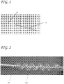
- the balloon In its deflated state ( Fig. 1 ), the balloon is in the form of a tube of compliant material with a diameter, in one preferred embodiment, of up to 1/15 of the final crossing profile of the inflated balloon.
- the tube can be constructed with a uniform wall thickness or with a wall thickness which varies along its length.
- the collapsed balloon is indicated in Fig. 1 by part number 12 attached to catheter shaft 10.
- the balloon can be made from one material. Alternatively, it may be constructed from two or more different materials, thereby producing a non-uniform spiral balloon upon inflation. Suitable materials for use in constructing the compliant balloon include (but are not limited to): silicones and thermoplastic elastomers (TPEs) such as (but not limited to) Evoperene and Monoprene.
- TPEs thermoplastic elastomers
- the balloon may be manufactured from these materials using standard balloon production techniques well known to the skilled artisan in this field.
- the balloon 12 is bound at two points to a rigid or semi-rigid conduit 10 which is threaded through the balloon. Since the balloon is made of a compliant material it elongates during inflation.
- the attachment of the balloon to the catheter conduit may be achieved using any of the standard bonding techniques and materials well known in the art, for example adhesion using biocompatible glues such as silicone glue.
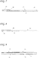
- the balloon 12 Since the balloon 12 is bound at both its ends, its longitudinal elongation is restrained. Provided certain balloon-related design parameter criteria are met (as will be discussed hereinbelow), said balloon 12 will then buckle and assume a spiral shape as shown in Figs. 2 and 3 .
- Fig. 3 illustrates a preferred embodiment of the balloon catheter which further comprises an aspiration element 14.
- the general form of this element is a low-profile suction tube, the proximal end of which is connected to a negative pressure source, and the open distal end of which is located close to the proximal neck of the balloon.
- the aspiration element is bound to the catheter conduit by means of loops, ties or any other suitable method.
- the aspiration element may be unattached to the catheter conduit.
- the aspiration tube may be made from any suitable biocompatible material such as (but not limited to) Pebax and Nylon.
- the aspiration tube may have an external diameter of 6Fr and an internal diameter of 0.070".
- Typical aspiration pressures are in the order of 640 to 680 mmHg, and may be provided by standard negative pressure sources such as are available in hospitals and other healthcare centers.
- Fig. 3 also illustrates that when compliant balloon 12 is inflated, a spiral channel 16 is formed. The presence of this channel is advantageous for at least two reasons. Firstly, the presence of the open channel prevents occlusion of the blood vessel when the balloon is fully inflated. Secondly, in some embodiments of the invention, the spiral channel may be used for the capture and removal of particulate matter (e.g. thrombotic material) from the blood vessel.
- particulate matter e.g. thrombotic material
- the embodiment of the device illustrated in Fig. 3 is capable of removal of a large thrombus from vessels using a low profile catheter that can be introduced into the body using a 5-Fr introducer.
- thrombus removal is achieved by altering the thrombus shape (e.g. by causing elongation and flattening thereof) so that it can be easily aspirated through the low profile aspiration tube and thereby removed from the body.
- a method for removing particulate matter from body passages for example - thrombus material from blood vessels
- Fig. 4 deflated state
- Fig. 5 inflated state
- N the number of spiral threads
- N the number of spiral threads
- a compliant balloon having a length of 30 mm, an outer diameter of 1 mm and a wall thickness of 0.25 mm readily adopts a spiral conformation upon inflation, provided that both ends of said balloon are bound to a rigid conduit.
- the compliant balloon will have a length in the range of 15mm to 50 mm and a wall thickness in the range of 100 micron to 400 micron. It should be emphasized that the preceding dimensions (and all other dimensions that appear herein) are exemplary values only, and should not be construed as limiting the size of the presently-disclosed device in any way.
- the general embodiment of the balloon catheter of the present invention that is described hereinabove and depicted in Figs. 1 to 3 comprises a single catheter conduit to which the compliant balloon is attached.
- the device of the present invention may have a two-conduit conformation, with (for example) the proximal neck of the balloon being attached to the outer surface of an outer conduit, while the distal neck thereof is attached to the outer surface of an inner conduit that is disposed within the lumen of said outer conduit.
- the inner conduit will generally extend beyond the distal end of the outer conduit.
- the device of the present invention may also comprise one or more conduits having multiple lumens (e.g. bi-lumen catheters) where the additional lumens may be used for a variety of purposes, including the passage of guidewires, instrumentation or tools.
- the catheter is constructed of a single-lumen stainless steel tube with a distally assembled spiral balloon ( Fig. 6 ).
- the deflated cross profile ranges between 0.4 and 0.8 mm.
- the tube may be delivered to the target through a 0.8 mm diameter (2.4 Fr) or 1.26 mm diameter 3.8 Fr microcatheter.
- the catheter tube 18 can have a laser cut (spiral cut or grooves) at its distal section or all along its length to increase its flexibility.
- a thin (approximately 0.013 mm (0.0005")) polymeric jacket 19 is applied over the tube (e.g. by a heat-shrink process) .
- An aperture 26 is created at the distal section of the hypotube for the inflation of the spiral balloon.
- the distal end of the hypotube 28 is plugged by using a plasma weld process, laser weld process or adhesive process.
- the compliant balloon 24 is shown in this figure and in the figures that follow in its deflated state.
- the aforementioned spiral-forming balloon 24 is attached at its ends to the distal portion of the hypotube (in a non-spiral, conventional manner) by means of thermo-bonding or adhesive technology.
- a reduced cross-section profile of the distal portion of the hypotube 20 (i.e. in the region of the balloon attachment) is obtained by longitudinally slicing said portion, thereby creating a reduced diameter tube region 22 of approximately semicircular cross sectional form.
- a stainless steel wire 30 having a diameter of, for example, 0.2 mm may be welded to the distal end of the tube 20.
- a balloon 24 with a smaller ID may be used, thereby leading to a distal section having a significantly smaller cross section profile.
- the catheter may be delivered (in either over-the-wire or rapid exchange mode) over a coronary 0.35 mm (0.014") guidewire ( Fig. 9 ).
- the minimum cross sectional profile of the catheter may be in the order of 0.8-1.0 mm.
- the balloon 24 depicted in the longitudinal section shown in Fig. 9 is mounted in a conventional manner on a two-conduit coaxial design catheter similar to standard balloon catheters known in art, with the proximal end of the balloon 24 being attached to the outer tube 34 and the distal end thereof being attached to the inner tube 32.
- Both the inner tube and the outer tube may be constructed by the use of extrusion techniques from materials commonly used in the art including Nylon, Pebax, PET and Polyurethane.
- the balloon 24 is inflated in a conventional manner well known to skilled artisans in the field, through an inflation lumen formed by the space between the inner and outer tubes.
- the lumen of the inner conduit functions primarily as a guidewire lumen.
- the presence of one or more side exits (or apertures) 38 proximal to the balloon that communicate between said guidewire lumen 36 and the area surrounding the outer tube permit said lumen to be additionally used for the delivery of liquid substances of various types to the region of the blood vessel that is in proximity to said exit(s).
- the guidewire lumen may used for injecting liquids (including, but not limited to standard contrast media and thrombolytic agents, such as tPA) through both the side exit and distal exit of the lumen.
- liquids including, but not limited to standard contrast media and thrombolytic agents, such as tPA
- fluid injection takes place while the guidewire is still indwelling.
- the aforementioned side aperture 38 will generally be sized such that its surface area will be approximately equal to the cross-sectional area of the inner tube lumen.
- the aperture is formed by means of a laser cut, and the side walls of said aperture are sealed by thermo-bonding methods, in order to prevent seepage between the inner and outer tubes.
- thrombolytic agents In the case of injection of thrombolytic agents through the catheter it is of utmost importance to avoid injecting said agents on the distal side of the balloon. In order to prevent this occurrence, the distal opening of the catheter needs to be capable of being blocked, while the side exit remains open. Moreover, injection of thrombolytic agents proximal to the balloon, and in the vicinity of the thrombus (by the aforementioned means of blocking the distal opening while retaining the side aperture open) beneficially enhances the dissolution of the thrombus. While several different technical solutions may be employed in order to achieve closure of the distal opening, while retaining an open side aperture, the following designs represent particularly preferred embodiments:
- the conduits used to construct the catheter device of the present invention may be made of any suitable material including (but not limited to) a biocompatible polymer such as polyurethane or nylon or PET, or a biocompatible metal such as stainless steel, and may be manufactured utilizing conventional methods, such as extrusion and laser cutting.
- the diameter of the conduits is generally in the range of 0.5-2.0 mm, and their length is generally in the range of 100-2000 mm.
- the compliant balloon may be inflated by introducing a pressurized inflation media via an inflation fluid port that is in fluid connection with a source of pressurized media and a pumping device or syringe.
- the inflation media passes through openings in the wall of the catheter shaft located between the proximal and distal attachment points of the balloon.
- the inflation media passes via an inflation fluid lumen formed between the inner wall of the outer conduit and the outer surface of the inner conduit.
- the balloon of the present invention may be assembled onto a two-conduit catheter, wherein the inner conduit is movable in relation to the outer conduit.
- the cross-sectional profile of the non-inflated balloon may be reduced even further by means of moving the inner tube distally prior to insertion of the catheter into the vasculature, thereby stretching the balloon and thus reducing its wall thickness.
- Typical procedure for using a balloon catheter of the present invention (fitted with an aspiration tube) to remove thrombotic material from a blood vessel:
- the spiral-forming balloon catheter of the present invention has many different applications, in addition to the use in thrombus removal described above.
- the expanded spiral balloon may be used for anchoring a catheter (or other elongate device) within a blood vessel, without blocking blood flow in the region of the anchoring balloon.
- the spiral balloon may be used for the purpose of cooling or heating tissue or blood in the immediate vicinity of said balloon.
- the balloon may be covered or partly covered with a network of thin filaments, thereby creating a distal protection element, which may serve to enhance the ability of the spiral balloon to trap thrombotic material during withdrawal of the catheter.
- a further application for the spiral-forming balloon of the present invention is in the treatment and/or remodeling of vascular aneurysms (including, but not limited to, cerebral aneurysms).
- vascular aneurysms including, but not limited to, cerebral aneurysms.
- Prior art methods of treatment generally use an inflated catheter balloon as a 'floor' or base during the insertion of coils into the aneurysm that is being re-modeled.
- blockage total or near-total
- This blockage may clearly have serious negative implications, particularly when dealing with a cerebral aneurysm.
- the use of a spiral-forming balloon of the present invention permits blood flow to continue through and around the spiral channels, thereby preventing ischemic and hypoxic damage to sensitive tissues distal to the treatment site.
- said catheter following insertion of the catheter system of the present invention into the body, and its arrival at the intended working site, said catheter may be left in situ for periods of up to several hours, in order perform its various functions (e.g. thrombus collection) as a temporary indwelling device.
Landscapes
- Health & Medical Sciences (AREA)
- Life Sciences & Earth Sciences (AREA)
- Heart & Thoracic Surgery (AREA)
- Public Health (AREA)
- Animal Behavior & Ethology (AREA)
- Veterinary Medicine (AREA)
- Engineering & Computer Science (AREA)
- Anesthesiology (AREA)
- Biomedical Technology (AREA)
- Hematology (AREA)
- General Health & Medical Sciences (AREA)
- Biophysics (AREA)
- Child & Adolescent Psychology (AREA)
- Pulmonology (AREA)
- Vascular Medicine (AREA)
- Media Introduction/Drainage Providing Device (AREA)
- Materials For Medical Uses (AREA)
Applications Claiming Priority (4)
| Application Number | Priority Date | Filing Date | Title |
|---|---|---|---|
| US92014507P | 2007-03-27 | 2007-03-27 | |
| US97812207P | 2007-10-07 | 2007-10-07 | |
| US3879508P | 2008-03-24 | 2008-03-24 | |
| PCT/IB2008/051158 WO2008117256A2 (en) | 2007-03-27 | 2008-03-27 | Spiral balloon catheter |
Publications (2)
| Publication Number | Publication Date |
|---|---|
| EP2134405A2 EP2134405A2 (en) | 2009-12-23 |
| EP2134405B1 true EP2134405B1 (en) | 2021-06-02 |
Family
ID=39789110
Family Applications (2)
| Application Number | Title | Priority Date | Filing Date |
|---|---|---|---|
| EP08763022.4A Active EP2134405B1 (en) | 2007-03-27 | 2008-03-27 | Spiral balloon catheter |
| EP08763023.2A Active EP2136869B1 (en) | 2007-03-27 | 2008-03-27 | Spiral balloon catheter |
Family Applications After (1)
| Application Number | Title | Priority Date | Filing Date |
|---|---|---|---|
| EP08763023.2A Active EP2136869B1 (en) | 2007-03-27 | 2008-03-27 | Spiral balloon catheter |
Country Status (7)
| Country | Link |
|---|---|
| US (4) | US7766871B2 (cg-RX-API-DMAC7.html) |
| EP (2) | EP2134405B1 (cg-RX-API-DMAC7.html) |
| JP (4) | JP2010522601A (cg-RX-API-DMAC7.html) |
| CN (2) | CN101743032B (cg-RX-API-DMAC7.html) |
| CA (2) | CA2681923C (cg-RX-API-DMAC7.html) |
| ES (1) | ES2884648T3 (cg-RX-API-DMAC7.html) |
| WO (2) | WO2008117257A2 (cg-RX-API-DMAC7.html) |
Families Citing this family (79)
| Publication number | Priority date | Publication date | Assignee | Title |
|---|---|---|---|---|
| US8425549B2 (en) | 2002-07-23 | 2013-04-23 | Reverse Medical Corporation | Systems and methods for removing obstructive matter from body lumens and treating vascular defects |
| GB0306176D0 (en) | 2003-03-18 | 2003-04-23 | Imp College Innovations Ltd | Tubing |
| ATE446065T1 (de) | 2003-03-18 | 2009-11-15 | Veryan Medical Ltd | Spiralförmiger stent |
| WO2008095052A2 (en) | 2007-01-30 | 2008-08-07 | Loma Vista Medical, Inc., | Biological navigation device |
| WO2009134686A1 (en) * | 2008-04-27 | 2009-11-05 | Loma Vista Medical, Inc. | Biological navigation device |
| CN101743032B (zh) * | 2007-03-27 | 2012-09-19 | 因特拉泰克医药有限公司 | 螺旋囊体导管 |
| US9198687B2 (en) | 2007-10-17 | 2015-12-01 | Covidien Lp | Acute stroke revascularization/recanalization systems processes and products thereby |
| US9220522B2 (en) | 2007-10-17 | 2015-12-29 | Covidien Lp | Embolus removal systems with baskets |
| US8585713B2 (en) | 2007-10-17 | 2013-11-19 | Covidien Lp | Expandable tip assembly for thrombus management |
| US8066757B2 (en) | 2007-10-17 | 2011-11-29 | Mindframe, Inc. | Blood flow restoration and thrombus management methods |
| US11337714B2 (en) | 2007-10-17 | 2022-05-24 | Covidien Lp | Restoring blood flow and clot removal during acute ischemic stroke |
| US8926680B2 (en) | 2007-11-12 | 2015-01-06 | Covidien Lp | Aneurysm neck bridging processes with revascularization systems methods and products thereby |
| US10123803B2 (en) | 2007-10-17 | 2018-11-13 | Covidien Lp | Methods of managing neurovascular obstructions |
| US8088140B2 (en) | 2008-05-19 | 2012-01-03 | Mindframe, Inc. | Blood flow restorative and embolus removal methods |
| EP2254485B1 (en) | 2008-02-22 | 2017-08-30 | Covidien LP | Apparatus for flow restoration |
| EP2271390A4 (en) | 2008-04-11 | 2016-07-20 | Covidien Lp | MONORAIL NEURO MICRO CATHETER FOR DISTRIBUTING MEDICAL DEVICES FOR THE TREATMENT OF STROKE, PROCESSES AND PRODUCTS |
| WO2009134337A1 (en) | 2008-05-01 | 2009-11-05 | Aneuclose Llc | Aneurysm occlusion device |
| EP2300094B1 (en) | 2008-06-02 | 2013-07-24 | Loma Vista Medical, Inc., | Inflatable medical devices |
| US8939991B2 (en) | 2008-06-08 | 2015-01-27 | Hotspur Technologies, Inc. | Apparatus and methods for removing obstructive material from body lumens |
| US8945160B2 (en) | 2008-07-03 | 2015-02-03 | Hotspur Technologies, Inc. | Apparatus and methods for treating obstructions within body lumens |
| EP2307086B1 (en) * | 2008-07-03 | 2015-04-15 | Hotspur Technologies, Inc | Apparatus for treating obstructions within body lumens |
| US9101382B2 (en) | 2009-02-18 | 2015-08-11 | Hotspur Technologies, Inc. | Apparatus and methods for treating obstructions within body lumens |
| WO2010041039A1 (en) | 2008-10-10 | 2010-04-15 | Veryan Medical Limited | A medical device suitable for location in a body lumen |
| EP2349123B1 (en) * | 2008-10-10 | 2015-11-04 | Veryan Medical Limited | A medical device |
| US9539120B2 (en) * | 2008-10-10 | 2017-01-10 | Veryan Medical Ltd. | Medical device suitable for location in a body lumen |
| US9597214B2 (en) | 2008-10-10 | 2017-03-21 | Kevin Heraty | Medical device |
| US10987494B2 (en) | 2008-11-11 | 2021-04-27 | Covidien Lp | Pleated or folded catheter-mounted balloon |
| US20120109057A1 (en) | 2009-02-18 | 2012-05-03 | Hotspur Technologies, Inc. | Apparatus and methods for treating obstructions within body lumens |
| US10456276B2 (en) | 2009-05-08 | 2019-10-29 | Veryan Medical Limited | Medical device suitable for location in a body lumen |
| WO2010128311A1 (en) * | 2009-05-08 | 2010-11-11 | Veryan Medical Limited | A medical device suitable for location in a body lumen |
| US8906057B2 (en) | 2010-01-04 | 2014-12-09 | Aneuclose Llc | Aneurysm embolization by rotational accumulation of mass |
| US8540669B2 (en) | 2010-04-30 | 2013-09-24 | Abbott Cardiovascular Systems Inc. | Catheter system providing step reduction for postconditioning |
| WO2011136815A1 (en) | 2010-04-30 | 2011-11-03 | Abbott Cardiovascular Systems Inc. | Catheter system having a fluid circuit |
| US9168361B2 (en) | 2010-04-30 | 2015-10-27 | Abbott Cardiovascular Systems Inc. | Balloon catheter exhibiting rapid inflation and deflation |
| CN102939126B (zh) * | 2010-04-30 | 2015-09-16 | 雅培心脏血管系统股份有限公司 | 呈现迅速膨胀和收缩的改进型球囊导管 |
| EP3552655B1 (en) | 2010-07-13 | 2020-12-23 | Loma Vista Medical, Inc. | Inflatable medical devices |
| US9084609B2 (en) * | 2010-07-30 | 2015-07-21 | Boston Scientific Scime, Inc. | Spiral balloon catheter for renal nerve ablation |
| US10188436B2 (en) | 2010-11-09 | 2019-01-29 | Loma Vista Medical, Inc. | Inflatable medical devices |
| US9138232B2 (en) | 2011-05-24 | 2015-09-22 | Aneuclose Llc | Aneurysm occlusion by rotational dispensation of mass |
| US10022127B2 (en) * | 2011-11-02 | 2018-07-17 | Abbott Cardiovascular Systems Inc. | Double bellow occluder for sclerotherapy |
| US9126013B2 (en) | 2012-04-27 | 2015-09-08 | Teleflex Medical Incorporated | Catheter with adjustable guidewire exit position |
| US8951296B2 (en) * | 2012-06-29 | 2015-02-10 | Medtronic Ardian Luxembourg S.A.R.L. | Devices and methods for photodynamically modulating neural function in a human |
| US9277905B2 (en) | 2012-08-02 | 2016-03-08 | W. L. Gore & Associates, Inc. | Space-filling device |
| WO2014030078A1 (en) | 2012-08-23 | 2014-02-27 | Strait Access Technologies Holdings (Pty) Ltd | Inflatable distender |
| US10286184B2 (en) * | 2012-10-01 | 2019-05-14 | Qmax, Llc | Helical balloon catheter |
| WO2014138410A1 (en) * | 2013-03-08 | 2014-09-12 | Symple Surgical Inc. | Balloon catheter apparatus with microwave emitter |
| US10076384B2 (en) | 2013-03-08 | 2018-09-18 | Symple Surgical, Inc. | Balloon catheter apparatus with microwave emitter |
| US10076404B2 (en) | 2013-03-12 | 2018-09-18 | Boston Scientific Limited | Catheter system with balloon-operated filter sheath and fluid flow maintenance |
| EP3582334A1 (en) * | 2013-07-01 | 2019-12-18 | TE Connectivity Nederland B.V. | Socket assembly for a combined power and data connector |
| EP2848225A1 (en) * | 2013-09-13 | 2015-03-18 | Covidien LP | A pleated or folded catheter-mounted balloon |
| WO2015061801A2 (en) * | 2013-10-26 | 2015-04-30 | Accumed Radial Systems Llc | System, apparatus, and method for creating a lumen |
| WO2015123320A1 (en) * | 2014-02-11 | 2015-08-20 | All Cape Gynecology Llc | Endocyte cannula |
| US10182841B1 (en) * | 2015-06-16 | 2019-01-22 | C.R. Bard, Inc. | Medical balloon with enhanced focused force control |
| US12171962B2 (en) | 2015-07-13 | 2024-12-24 | Biotronik Ag | Mechanically actuated and functionally integratable catheter system for treating vascular and non-vascular diseases and related methods |
| CN108366799B (zh) * | 2015-11-09 | 2023-01-03 | 瑞普医药有限公司 | 用于心血管治疗的血流量减压器 |
| CN109475418A (zh) | 2016-07-13 | 2019-03-15 | 波士顿科学国际有限公司 | 用于在与近旁手术相邻的血管内维持畅通性的器械和方法 |
| US10492937B2 (en) | 2016-10-17 | 2019-12-03 | Cook Medical Technologies Llc | Deploying a balloon expandable stent to induce spiral flow |
| US11083876B2 (en) * | 2017-02-15 | 2021-08-10 | Tevar (Pty) Ltd | Dilation device |
| WO2018217486A1 (en) * | 2017-05-23 | 2018-11-29 | Cryterion Medical, Inc. | Cryoballoon for intravascular catheter system |
| US10765475B2 (en) | 2017-10-31 | 2020-09-08 | Biosense Webster (Israel) Ltd. | All-in-one spiral catheter |
| US10918390B2 (en) * | 2018-03-30 | 2021-02-16 | DePuy Synthes Products, Inc. | Helical balloon assist device and method for using the same |
| US10786259B2 (en) | 2018-03-30 | 2020-09-29 | DePuy Synthes Products, Inc. | Split balloon assist device and method for using the same |
| US11471582B2 (en) | 2018-07-06 | 2022-10-18 | Incept, Llc | Vacuum transfer tool for extendable catheter |
| WO2020121309A1 (en) | 2018-12-11 | 2020-06-18 | Revamp Medical Ltd. | Systems, devices, and methods for adjusting blood flow in a body lumen |
| GB201820151D0 (en) * | 2018-12-11 | 2019-01-23 | Cook Medical Technologies Llc | Introducer assembly particularly for balloon catheters |
| US11638637B2 (en) | 2019-12-18 | 2023-05-02 | Imperative Care, Inc. | Method of removing embolic material with thrombus engagement tool |
| US12251512B2 (en) * | 2020-06-18 | 2025-03-18 | Covidien Lp | Physiologically conformable tracheal tube |
| WO2022157607A1 (en) * | 2021-01-25 | 2022-07-28 | Alcon Inc. | Method and apparatus for subretinal injection |
| US20240041465A1 (en) | 2021-02-08 | 2024-02-08 | Intratech Medical Ltd. | Spiral-forming balloon for coronary sinus use |
| WO2022218922A2 (en) * | 2021-04-12 | 2022-10-20 | Medtronic Ireland Manufacturing Unlimited Company | Chemical ablation therapy delivery system |
| US20230048388A1 (en) | 2021-08-12 | 2023-02-16 | Imperative Care, Inc. | Robotically driven interventional device |
| USD1077996S1 (en) | 2021-10-18 | 2025-06-03 | Imperative Care, Inc. | Inline fluid filter |
| CN114732955A (zh) * | 2022-04-19 | 2022-07-12 | 苏州大学 | 花瓣形双层人工血管及其制备方法 |
| CN116549818A (zh) * | 2023-05-16 | 2023-08-08 | 武汉合畅慧通医疗科技有限公司 | 一种液电碎石用多功能碎石导管系统 |
| CN117959050A (zh) * | 2024-04-01 | 2024-05-03 | 上海宏普医疗器械有限公司 | 一种可回收的螺旋球囊支架 |
| CN118415715B (zh) * | 2024-07-05 | 2024-08-23 | 北京华脉泰科医疗器械股份有限公司 | 附壁血栓清除装置 |
| WO2026035576A1 (en) * | 2024-08-05 | 2026-02-12 | Fastwave Medical Inc. | Pleatless delivery intravascular lithotripsy system |
| CN118924381B (zh) * | 2024-10-14 | 2025-03-21 | 上海宏普医疗器械有限公司 | 一种多级血栓清除装置 |
| CN121102629B (zh) * | 2025-11-13 | 2026-03-13 | 杭州市中医院(浙江中医药大学附属杭州市中医院) | 一种造口灌肠套件装置 |
Family Cites Families (56)
| Publication number | Priority date | Publication date | Assignee | Title |
|---|---|---|---|---|
| US591386A (en) * | 1897-10-12 | Potato-planter | ||
| US4271839A (en) * | 1979-07-25 | 1981-06-09 | Thomas J. Fogarty | Dilation catheter method and apparatus |
| US4762130A (en) * | 1987-01-15 | 1988-08-09 | Thomas J. Fogarty | Catheter with corkscrew-like balloon |
| CN2049956U (zh) * | 1989-07-28 | 1989-12-27 | 王东亚 | 用于除去血管内血栓的导管系统 |
| US5295959A (en) * | 1992-03-13 | 1994-03-22 | Medtronic, Inc. | Autoperfusion dilatation catheter having a bonded channel |
| US5308356A (en) * | 1993-02-25 | 1994-05-03 | Blackshear Jr Perry L | Passive perfusion angioplasty catheter |
| US5383856A (en) * | 1993-03-19 | 1995-01-24 | Bersin; Robert M. | Helical spiral balloon catheter |
| US5395333A (en) | 1993-09-01 | 1995-03-07 | Scimed Life Systems, Inc. | Multi-lobed support balloon catheter with perfusion |
| US6896842B1 (en) | 1993-10-01 | 2005-05-24 | Boston Scientific Corporation | Medical device balloons containing thermoplastic elastomers |
| DE69433506T2 (de) | 1993-10-01 | 2004-06-24 | Boston Scientific Corp., Natick | Medizinische, thermoplastische elastomere enthaltende ballone |
| US5545132A (en) | 1993-12-21 | 1996-08-13 | C. R. Bard, Inc. | Helically grooved balloon for dilatation catheter and method of using |
| US5484411A (en) * | 1994-01-14 | 1996-01-16 | Cordis Corporation | Spiral shaped perfusion balloon and method of use and manufacture |
| FI1694U1 (fi) * | 1994-08-17 | 1995-01-12 | Alusystems Ky | Svaengbar balkongglaskonstruktion |
| NL1000106C2 (nl) | 1995-04-10 | 1996-10-11 | Cordis Europ | Balloncatheter met gelobde ballon en werkwijze voor het vervaardigen daarvan. |
| US5871475A (en) | 1995-06-05 | 1999-02-16 | Frassica; James J. | Catheter system |
| US5855546A (en) | 1996-02-29 | 1999-01-05 | Sci-Med Life Systems | Perfusion balloon and radioactive wire delivery system |
| US5735816A (en) | 1996-07-23 | 1998-04-07 | Medtronic, Inc. | Spiral sheath retainer for autoperfusion dilatation catheter balloon |
| US5749852A (en) | 1996-07-23 | 1998-05-12 | Medtronic, Inc. | Sheath system for autoperfusion dilatation catheter balloon |
| US6123712A (en) * | 1996-08-23 | 2000-09-26 | Scimed Life Systems, Inc. | Balloon catheter with stent securement means |
| US5954740A (en) | 1996-09-23 | 1999-09-21 | Boston Scientific Corporation | Catheter balloon having raised radial segments |
| US5797948A (en) * | 1996-10-03 | 1998-08-25 | Cordis Corporation | Centering balloon catheter |
| CA2217092C (en) * | 1996-10-03 | 2007-07-10 | Cordis Corporation | Centering balloon catheter |
| JPH10179749A (ja) * | 1996-12-24 | 1998-07-07 | Buaayu:Kk | インフュージョンカテーテル |
| US5814064A (en) | 1997-03-06 | 1998-09-29 | Scimed Life Systems, Inc. | Distal protection device |
| US5891386A (en) | 1997-04-25 | 1999-04-06 | Medtronic, Inc. | Method for making catheter balloons |
| WO1999020324A1 (en) | 1997-10-20 | 1999-04-29 | Bersin Robert D | Helical spiral balloon catheter |
| US6716236B1 (en) | 1998-04-21 | 2004-04-06 | Alsius Corporation | Intravascular catheter with heat exchange element having inner inflation element and methods of use |
| US6129706A (en) | 1998-12-10 | 2000-10-10 | Janacek; Jaroslav | Corrugated catheter balloon |
| US6743196B2 (en) * | 1999-03-01 | 2004-06-01 | Coaxia, Inc. | Partial aortic occlusion devices and methods for cerebral perfusion augmentation |
| US6350271B1 (en) | 1999-05-17 | 2002-02-26 | Micrus Corporation | Clot retrieval device |
| US6350253B1 (en) * | 1999-07-19 | 2002-02-26 | I-Flow Corporation | Catheter for uniform delivery of medication |
| JP2001029475A (ja) * | 1999-07-23 | 2001-02-06 | Kanegafuchi Chem Ind Co Ltd | 血液灌流バルーンカテーテル |
| US6340364B2 (en) | 1999-10-22 | 2002-01-22 | Nozomu Kanesaka | Vascular filtering device |
| US6450988B1 (en) | 1999-12-29 | 2002-09-17 | Advanced Cardiovascular Systems, Inc. | Centering catheter with improved perfusion |
| US6443926B1 (en) * | 2000-02-01 | 2002-09-03 | Harold D. Kletschka | Embolic protection device having expandable trap |
| JP2001252987A (ja) * | 2000-03-13 | 2001-09-18 | Jiro Fukuda | スパイラルバルーン |
| US6478807B1 (en) | 2000-06-08 | 2002-11-12 | Advanced Cardiovascular Systems, Inc. | Pre-formed expandable member having grooves |
| US6875212B2 (en) * | 2000-06-23 | 2005-04-05 | Vertelink Corporation | Curable media for implantable medical device |
| US6527739B1 (en) | 2000-12-29 | 2003-03-04 | Advanced Cardiovascular Systems, Inc. | Spiraled balloon arrangement for treatment of a tortuous vessel |
| US6679860B2 (en) | 2001-06-19 | 2004-01-20 | Medtronic Ave, Inc. | Intraluminal therapy catheter with inflatable helical member and methods of use |
| US6776945B2 (en) | 2001-07-03 | 2004-08-17 | Scimed Life Systems, Inc. | Medical device with extruded member having helical orientation |
| DE60317474T2 (de) * | 2002-03-05 | 2008-10-02 | Salviac Ltd. | System aus embolischem filter und rückziehschlinge |
| US20050171572A1 (en) | 2002-07-31 | 2005-08-04 | Microvention, Inc. | Multi-layer coaxial vaso-occlusive device |
| US6945957B2 (en) | 2002-12-30 | 2005-09-20 | Scimed Life Systems, Inc. | Valve treatment catheter and methods |
| US6923808B2 (en) | 2003-02-24 | 2005-08-02 | Boston Scientific Scimed, Inc. | Probes having helical and loop shaped inflatable therapeutic elements |
| US7122003B2 (en) | 2003-04-16 | 2006-10-17 | Granit Medical Innovations, Llc | Endoscopic retractor instrument and associated method |
| CA2523985A1 (en) | 2003-05-19 | 2004-11-25 | Kaneka Corporation | Balloon catheter and method of manufacturing the same |
| US20050177130A1 (en) | 2004-02-10 | 2005-08-11 | Angioscore, Inc. | Balloon catheter with spiral folds |
| US20050228417A1 (en) | 2004-03-26 | 2005-10-13 | Teitelbaum George P | Devices and methods for removing a matter from a body cavity of a patient |
| US7462175B2 (en) * | 2004-04-21 | 2008-12-09 | Acclarent, Inc. | Devices, systems and methods for treating disorders of the ear, nose and throat |
| US7491188B2 (en) * | 2004-10-12 | 2009-02-17 | Boston Scientific Scimed, Inc. | Reinforced and drug-eluting balloon catheters and methods for making same |
| US7457661B2 (en) * | 2005-03-24 | 2008-11-25 | Medtronic Vascular, Inc. | Catheter-based, dual coil photopolymerization system |
| US10076641B2 (en) * | 2005-05-11 | 2018-09-18 | The Spectranetics Corporation | Methods and systems for delivering substances into luminal walls |
| US8246641B2 (en) | 2006-11-08 | 2012-08-21 | Cook Medical Technolgies, LLC | Thrombus removal device |
| US7914549B2 (en) | 2007-01-05 | 2011-03-29 | Hesham Morsi | Mechanical embolectomy and suction catheter |
| CN101743032B (zh) | 2007-03-27 | 2012-09-19 | 因特拉泰克医药有限公司 | 螺旋囊体导管 |
-
2008
- 2008-03-27 CN CN2008800139286A patent/CN101743032B/zh not_active Expired - Fee Related
- 2008-03-27 CA CA2681923A patent/CA2681923C/en active Active
- 2008-03-27 JP JP2010500417A patent/JP2010522601A/ja active Pending
- 2008-03-27 US US12/078,191 patent/US7766871B2/en active Active
- 2008-03-27 EP EP08763022.4A patent/EP2134405B1/en active Active
- 2008-03-27 EP EP08763023.2A patent/EP2136869B1/en active Active
- 2008-03-27 CN CN2008800138353A patent/CN101730563B/zh not_active Expired - Fee Related
- 2008-03-27 US US12/593,226 patent/US20100114022A1/en not_active Abandoned
- 2008-03-27 CA CA2681925A patent/CA2681925C/en not_active Expired - Fee Related
- 2008-03-27 US US12/593,211 patent/US20100137793A1/en not_active Abandoned
- 2008-03-27 ES ES08763022T patent/ES2884648T3/es active Active
- 2008-03-27 WO PCT/IB2008/051160 patent/WO2008117257A2/en not_active Ceased
- 2008-03-27 WO PCT/IB2008/051158 patent/WO2008117256A2/en not_active Ceased
- 2008-03-27 JP JP2010500418A patent/JP2010522602A/ja active Pending
-
2010
- 2010-06-24 US US12/822,865 patent/US8079978B2/en not_active Expired - Fee Related
-
2013
- 2013-08-26 JP JP2013174342A patent/JP5944355B2/ja not_active Expired - Fee Related
-
2015
- 2015-09-07 JP JP2015175383A patent/JP2016025921A/ja active Pending
Non-Patent Citations (1)
| Title |
|---|
| None * |
Also Published As
| Publication number | Publication date |
|---|---|
| JP2016025921A (ja) | 2016-02-12 |
| JP2014012198A (ja) | 2014-01-23 |
| CA2681923A1 (en) | 2008-10-02 |
| US20100262124A1 (en) | 2010-10-14 |
| JP2010522602A (ja) | 2010-07-08 |
| JP2010522601A (ja) | 2010-07-08 |
| JP5944355B2 (ja) | 2016-07-05 |
| EP2136869A2 (en) | 2009-12-30 |
| ES2884648T3 (es) | 2021-12-10 |
| US20080306440A1 (en) | 2008-12-11 |
| EP2134405A2 (en) | 2009-12-23 |
| US7766871B2 (en) | 2010-08-03 |
| US20100137793A1 (en) | 2010-06-03 |
| US20100114022A1 (en) | 2010-05-06 |
| CN101730563A (zh) | 2010-06-09 |
| CN101743032B (zh) | 2012-09-19 |
| CN101743032A (zh) | 2010-06-16 |
| WO2008117257A2 (en) | 2008-10-02 |
| CA2681925A1 (en) | 2008-10-02 |
| US8079978B2 (en) | 2011-12-20 |
| EP2136869B1 (en) | 2021-07-21 |
| CA2681923C (en) | 2015-09-15 |
| CN101730563B (zh) | 2012-12-26 |
| WO2008117256A3 (en) | 2009-02-05 |
| WO2008117257A3 (en) | 2009-02-05 |
| WO2008117256A2 (en) | 2008-10-02 |
| CA2681925C (en) | 2015-06-30 |
Similar Documents
| Publication | Publication Date | Title |
|---|---|---|
| EP2134405B1 (en) | Spiral balloon catheter | |
| US11565082B2 (en) | Enhanced flexibility neurovascular catheter | |
| EP1942973B1 (en) | Catheter having oval aspiration lumen and method of making | |
| AU764958B2 (en) | Enhanced balloon dilatation system | |
| JP7640040B2 (ja) | 調製不要なバルーン・ガイド・カテーテル | |
| US20120172798A1 (en) | Devices and methods for accessing a cerebral vessel | |
| US20130268050A1 (en) | Devices and methods for accessing a cerebral vessel | |
| US20080065045A1 (en) | Intracranial aspiration catheter | |
| CN114984407A (zh) | 在颅内血管中执行医疗手术的系统、导管和导管前进装置 | |
| JP2009513246A5 (cg-RX-API-DMAC7.html) | ||
| JPH10513382A (ja) | フレキシブルなニチノール製ワイアを有する食道用拡張バルーンカテーテル | |
| HK40079378A (zh) | 在颅内血管中执行医疗手术的系统、导管和导管前进装置 | |
| HK40079893A (en) | System for performing a medical procedure in an cerebral vessel and intravascular advancement system | |
| HK40015164A (en) | Aspiration catheter systems and methods of use | |
| JP2007202614A (ja) | カテーテル |
Legal Events
| Date | Code | Title | Description |
|---|---|---|---|
| PUAI | Public reference made under article 153(3) epc to a published international application that has entered the european phase |
Free format text: ORIGINAL CODE: 0009012 |
|
| 17P | Request for examination filed |
Effective date: 20091020 |
|
| AK | Designated contracting states |
Kind code of ref document: A2 Designated state(s): AT BE BG CH CY CZ DE DK EE ES FI FR GB GR HR HU IE IS IT LI LT LU LV MC MT NL NO PL PT RO SE SI SK TR |
|
| DAX | Request for extension of the european patent (deleted) | ||
| STAA | Information on the status of an ep patent application or granted ep patent |
Free format text: STATUS: EXAMINATION IS IN PROGRESS |
|
| 17Q | First examination report despatched |
Effective date: 20170926 |
|
| GRAP | Despatch of communication of intention to grant a patent |
Free format text: ORIGINAL CODE: EPIDOSNIGR1 |
|
| STAA | Information on the status of an ep patent application or granted ep patent |
Free format text: STATUS: GRANT OF PATENT IS INTENDED |
|
| INTG | Intention to grant announced |
Effective date: 20201217 |
|
| GRAS | Grant fee paid |
Free format text: ORIGINAL CODE: EPIDOSNIGR3 |
|
| GRAA | (expected) grant |
Free format text: ORIGINAL CODE: 0009210 |
|
| STAA | Information on the status of an ep patent application or granted ep patent |
Free format text: STATUS: THE PATENT HAS BEEN GRANTED |
|
| REG | Reference to a national code |
Ref country code: CH Ref legal event code: EP |
|
| AK | Designated contracting states |
Kind code of ref document: B1 Designated state(s): AT BE BG CH CY CZ DE DK EE ES FI FR GB GR HR HU IE IS IT LI LT LU LV MC MT NL NO PL PT RO SE SI SK TR |
|
| RAP3 | Party data changed (applicant data changed or rights of an application transferred) |
Owner name: INTRATECH MEDICAL LTD. |
|
| REG | Reference to a national code |
Ref country code: GB Ref legal event code: FG4D |
|
| REG | Reference to a national code |
Ref country code: AT Ref legal event code: REF Ref document number: 1397868 Country of ref document: AT Kind code of ref document: T Effective date: 20210615 |
|
| REG | Reference to a national code |
Ref country code: IE Ref legal event code: FG4D |
|
| REG | Reference to a national code |
Ref country code: DE Ref legal event code: R096 Ref document number: 602008064008 Country of ref document: DE |
|
| REG | Reference to a national code |
Ref country code: LT Ref legal event code: MG9D |
|
| PG25 | Lapsed in a contracting state [announced via postgrant information from national office to epo] |
Ref country code: BG Free format text: LAPSE BECAUSE OF FAILURE TO SUBMIT A TRANSLATION OF THE DESCRIPTION OR TO PAY THE FEE WITHIN THE PRESCRIBED TIME-LIMIT Effective date: 20210902 Ref country code: HR Free format text: LAPSE BECAUSE OF FAILURE TO SUBMIT A TRANSLATION OF THE DESCRIPTION OR TO PAY THE FEE WITHIN THE PRESCRIBED TIME-LIMIT Effective date: 20210602 Ref country code: LT Free format text: LAPSE BECAUSE OF FAILURE TO SUBMIT A TRANSLATION OF THE DESCRIPTION OR TO PAY THE FEE WITHIN THE PRESCRIBED TIME-LIMIT Effective date: 20210602 Ref country code: FI Free format text: LAPSE BECAUSE OF FAILURE TO SUBMIT A TRANSLATION OF THE DESCRIPTION OR TO PAY THE FEE WITHIN THE PRESCRIBED TIME-LIMIT Effective date: 20210602 |
|
| REG | Reference to a national code |
Ref country code: NL Ref legal event code: MP Effective date: 20210602 |
|
| REG | Reference to a national code |
Ref country code: AT Ref legal event code: MK05 Ref document number: 1397868 Country of ref document: AT Kind code of ref document: T Effective date: 20210602 |
|
| PG25 | Lapsed in a contracting state [announced via postgrant information from national office to epo] |
Ref country code: NO Free format text: LAPSE BECAUSE OF FAILURE TO SUBMIT A TRANSLATION OF THE DESCRIPTION OR TO PAY THE FEE WITHIN THE PRESCRIBED TIME-LIMIT Effective date: 20210902 Ref country code: PL Free format text: LAPSE BECAUSE OF FAILURE TO SUBMIT A TRANSLATION OF THE DESCRIPTION OR TO PAY THE FEE WITHIN THE PRESCRIBED TIME-LIMIT Effective date: 20210602 Ref country code: SE Free format text: LAPSE BECAUSE OF FAILURE TO SUBMIT A TRANSLATION OF THE DESCRIPTION OR TO PAY THE FEE WITHIN THE PRESCRIBED TIME-LIMIT Effective date: 20210602 Ref country code: LV Free format text: LAPSE BECAUSE OF FAILURE TO SUBMIT A TRANSLATION OF THE DESCRIPTION OR TO PAY THE FEE WITHIN THE PRESCRIBED TIME-LIMIT Effective date: 20210602 Ref country code: GR Free format text: LAPSE BECAUSE OF FAILURE TO SUBMIT A TRANSLATION OF THE DESCRIPTION OR TO PAY THE FEE WITHIN THE PRESCRIBED TIME-LIMIT Effective date: 20210903 |
|
| REG | Reference to a national code |
Ref country code: ES Ref legal event code: FG2A Ref document number: 2884648 Country of ref document: ES Kind code of ref document: T3 Effective date: 20211210 |
|
| PG25 | Lapsed in a contracting state [announced via postgrant information from national office to epo] |
Ref country code: AT Free format text: LAPSE BECAUSE OF FAILURE TO SUBMIT A TRANSLATION OF THE DESCRIPTION OR TO PAY THE FEE WITHIN THE PRESCRIBED TIME-LIMIT Effective date: 20210602 Ref country code: PT Free format text: LAPSE BECAUSE OF FAILURE TO SUBMIT A TRANSLATION OF THE DESCRIPTION OR TO PAY THE FEE WITHIN THE PRESCRIBED TIME-LIMIT Effective date: 20211004 Ref country code: NL Free format text: LAPSE BECAUSE OF FAILURE TO SUBMIT A TRANSLATION OF THE DESCRIPTION OR TO PAY THE FEE WITHIN THE PRESCRIBED TIME-LIMIT Effective date: 20210602 Ref country code: RO Free format text: LAPSE BECAUSE OF FAILURE TO SUBMIT A TRANSLATION OF THE DESCRIPTION OR TO PAY THE FEE WITHIN THE PRESCRIBED TIME-LIMIT Effective date: 20210602 Ref country code: EE Free format text: LAPSE BECAUSE OF FAILURE TO SUBMIT A TRANSLATION OF THE DESCRIPTION OR TO PAY THE FEE WITHIN THE PRESCRIBED TIME-LIMIT Effective date: 20210602 Ref country code: CZ Free format text: LAPSE BECAUSE OF FAILURE TO SUBMIT A TRANSLATION OF THE DESCRIPTION OR TO PAY THE FEE WITHIN THE PRESCRIBED TIME-LIMIT Effective date: 20210602 Ref country code: SK Free format text: LAPSE BECAUSE OF FAILURE TO SUBMIT A TRANSLATION OF THE DESCRIPTION OR TO PAY THE FEE WITHIN THE PRESCRIBED TIME-LIMIT Effective date: 20210602 |
|
| REG | Reference to a national code |
Ref country code: DE Ref legal event code: R097 Ref document number: 602008064008 Country of ref document: DE |
|
| PLBE | No opposition filed within time limit |
Free format text: ORIGINAL CODE: 0009261 |
|
| STAA | Information on the status of an ep patent application or granted ep patent |
Free format text: STATUS: NO OPPOSITION FILED WITHIN TIME LIMIT |
|
| PG25 | Lapsed in a contracting state [announced via postgrant information from national office to epo] |
Ref country code: DK Free format text: LAPSE BECAUSE OF FAILURE TO SUBMIT A TRANSLATION OF THE DESCRIPTION OR TO PAY THE FEE WITHIN THE PRESCRIBED TIME-LIMIT Effective date: 20210602 |
|
| 26N | No opposition filed |
Effective date: 20220303 |
|
| PG25 | Lapsed in a contracting state [announced via postgrant information from national office to epo] |
Ref country code: MC Free format text: LAPSE BECAUSE OF FAILURE TO SUBMIT A TRANSLATION OF THE DESCRIPTION OR TO PAY THE FEE WITHIN THE PRESCRIBED TIME-LIMIT Effective date: 20210602 |
|
| REG | Reference to a national code |
Ref country code: CH Ref legal event code: PL |
|
| REG | Reference to a national code |
Ref country code: BE Ref legal event code: MM Effective date: 20220331 |
|
| PG25 | Lapsed in a contracting state [announced via postgrant information from national office to epo] |
Ref country code: LU Free format text: LAPSE BECAUSE OF NON-PAYMENT OF DUE FEES Effective date: 20220327 Ref country code: LI Free format text: LAPSE BECAUSE OF NON-PAYMENT OF DUE FEES Effective date: 20220331 Ref country code: IE Free format text: LAPSE BECAUSE OF NON-PAYMENT OF DUE FEES Effective date: 20220327 Ref country code: CH Free format text: LAPSE BECAUSE OF NON-PAYMENT OF DUE FEES Effective date: 20220331 |
|
| PG25 | Lapsed in a contracting state [announced via postgrant information from national office to epo] |
Ref country code: BE Free format text: LAPSE BECAUSE OF NON-PAYMENT OF DUE FEES Effective date: 20220331 |
|
| PGFP | Annual fee paid to national office [announced via postgrant information from national office to epo] |
Ref country code: FR Payment date: 20230322 Year of fee payment: 16 |
|
| PGFP | Annual fee paid to national office [announced via postgrant information from national office to epo] |
Ref country code: GB Payment date: 20230321 Year of fee payment: 16 Ref country code: DE Payment date: 20230321 Year of fee payment: 16 |
|
| PGFP | Annual fee paid to national office [announced via postgrant information from national office to epo] |
Ref country code: IT Payment date: 20230328 Year of fee payment: 16 Ref country code: ES Payment date: 20230529 Year of fee payment: 16 |
|
| PG25 | Lapsed in a contracting state [announced via postgrant information from national office to epo] |
Ref country code: HU Free format text: LAPSE BECAUSE OF FAILURE TO SUBMIT A TRANSLATION OF THE DESCRIPTION OR TO PAY THE FEE WITHIN THE PRESCRIBED TIME-LIMIT; INVALID AB INITIO Effective date: 20080327 |
|
| PG25 | Lapsed in a contracting state [announced via postgrant information from national office to epo] |
Ref country code: CY Free format text: LAPSE BECAUSE OF FAILURE TO SUBMIT A TRANSLATION OF THE DESCRIPTION OR TO PAY THE FEE WITHIN THE PRESCRIBED TIME-LIMIT Effective date: 20210602 |
|
| PG25 | Lapsed in a contracting state [announced via postgrant information from national office to epo] |
Ref country code: TR Free format text: LAPSE BECAUSE OF FAILURE TO SUBMIT A TRANSLATION OF THE DESCRIPTION OR TO PAY THE FEE WITHIN THE PRESCRIBED TIME-LIMIT Effective date: 20210602 |
|
| PG25 | Lapsed in a contracting state [announced via postgrant information from national office to epo] |
Ref country code: MT Free format text: LAPSE BECAUSE OF FAILURE TO SUBMIT A TRANSLATION OF THE DESCRIPTION OR TO PAY THE FEE WITHIN THE PRESCRIBED TIME-LIMIT Effective date: 20210602 |
|
| REG | Reference to a national code |
Ref country code: DE Ref legal event code: R119 Ref document number: 602008064008 Country of ref document: DE |
|
| GBPC | Gb: european patent ceased through non-payment of renewal fee |
Effective date: 20240327 |
|
| PG25 | Lapsed in a contracting state [announced via postgrant information from national office to epo] |
Ref country code: DE Free format text: LAPSE BECAUSE OF NON-PAYMENT OF DUE FEES Effective date: 20241001 |
|
| PG25 | Lapsed in a contracting state [announced via postgrant information from national office to epo] |
Ref country code: GB Free format text: LAPSE BECAUSE OF NON-PAYMENT OF DUE FEES Effective date: 20240327 |
|
| PG25 | Lapsed in a contracting state [announced via postgrant information from national office to epo] |
Ref country code: FR Free format text: LAPSE BECAUSE OF NON-PAYMENT OF DUE FEES Effective date: 20240331 |
|
| PG25 | Lapsed in a contracting state [announced via postgrant information from national office to epo] |
Ref country code: GB Free format text: LAPSE BECAUSE OF NON-PAYMENT OF DUE FEES Effective date: 20240327 Ref country code: FR Free format text: LAPSE BECAUSE OF NON-PAYMENT OF DUE FEES Effective date: 20240331 Ref country code: DE Free format text: LAPSE BECAUSE OF NON-PAYMENT OF DUE FEES Effective date: 20241001 |
|
| PG25 | Lapsed in a contracting state [announced via postgrant information from national office to epo] |
Ref country code: IT Free format text: LAPSE BECAUSE OF NON-PAYMENT OF DUE FEES Effective date: 20240327 |
|
| REG | Reference to a national code |
Ref country code: ES Ref legal event code: FD2A Effective date: 20250506 |
|
| PG25 | Lapsed in a contracting state [announced via postgrant information from national office to epo] |
Ref country code: ES Free format text: LAPSE BECAUSE OF NON-PAYMENT OF DUE FEES Effective date: 20240328 |