EP2133704B2 - Prüfanordnung zur Wechselspannungsprüfung von elektrischen Hochspannungskomponenten - Google Patents
Prüfanordnung zur Wechselspannungsprüfung von elektrischen Hochspannungskomponenten Download PDFInfo
- Publication number
- EP2133704B2 EP2133704B2 EP08010691.7A EP08010691A EP2133704B2 EP 2133704 B2 EP2133704 B2 EP 2133704B2 EP 08010691 A EP08010691 A EP 08010691A EP 2133704 B2 EP2133704 B2 EP 2133704B2
- Authority
- EP
- European Patent Office
- Prior art keywords
- voltage
- container
- test
- test arrangement
- arrangement according
- Prior art date
- Legal status (The legal status is an assumption and is not a legal conclusion. Google has not performed a legal analysis and makes no representation as to the accuracy of the status listed.)
- Not-in-force
Links
Images
Classifications
-
- G—PHYSICS
- G01—MEASURING; TESTING
- G01R—MEASURING ELECTRIC VARIABLES; MEASURING MAGNETIC VARIABLES
- G01R31/00—Arrangements for testing electric properties; Arrangements for locating electric faults; Arrangements for electrical testing characterised by what is being tested not provided for elsewhere
- G01R31/50—Testing of electric apparatus, lines, cables or components for short-circuits, continuity, leakage current or incorrect line connections
- G01R31/58—Testing of lines, cables or conductors
-
- G—PHYSICS
- G01—MEASURING; TESTING
- G01R—MEASURING ELECTRIC VARIABLES; MEASURING MAGNETIC VARIABLES
- G01R31/00—Arrangements for testing electric properties; Arrangements for locating electric faults; Arrangements for electrical testing characterised by what is being tested not provided for elsewhere
- G01R31/12—Testing dielectric strength or breakdown voltage ; Testing or monitoring effectiveness or level of insulation, e.g. of a cable or of an apparatus, for example using partial discharge measurements; Electrostatic testing
- G01R31/1227—Testing dielectric strength or breakdown voltage ; Testing or monitoring effectiveness or level of insulation, e.g. of a cable or of an apparatus, for example using partial discharge measurements; Electrostatic testing of components, parts or materials
-
- G—PHYSICS
- G01—MEASURING; TESTING
- G01R—MEASURING ELECTRIC VARIABLES; MEASURING MAGNETIC VARIABLES
- G01R31/00—Arrangements for testing electric properties; Arrangements for locating electric faults; Arrangements for electrical testing characterised by what is being tested not provided for elsewhere
- G01R31/50—Testing of electric apparatus, lines, cables or components for short-circuits, continuity, leakage current or incorrect line connections
- G01R31/62—Testing of transformers
-
- H—ELECTRICITY
- H01—ELECTRIC ELEMENTS
- H01F—MAGNETS; INDUCTANCES; TRANSFORMERS; SELECTION OF MATERIALS FOR THEIR MAGNETIC PROPERTIES
- H01F27/00—Details of transformers or inductances, in general
- H01F27/40—Structural association with built-in electric component, e.g. fuse
- H01F27/402—Association of measuring or protective means
Definitions
- the invention relates to a test arrangement for AC testing of electrical high voltage components with at least one inverter, with at least one test transformer and with at least one high-voltage choke as test components, wherein at least said test components are arranged in a common cuboid container.
- high-voltage components such as power transformers
- High-voltage components such as power transformers have a very high weight, depending on the electrical rated power over 100 t.
- test arrangement with AC voltage generator and other components required for the test are transported in several assemblies to the location where the power transformer to be tested is located and assembled there to form a test arrangement.
- the high-voltage choke which is required for a resonance test to form a resonant circuit with the test specimen, can represent a test component of considerable size with a height of, for example, 2.5 m and an inner diameter of, for example, 1 m.
- the voltage divider which is needed to measure the high voltages of, for example, up to several 100kV in the resonant circuit, is a component of similar magnitude.
- the disadvantage is that the assembly of the various modules on site is associated with a considerable amount of time.
- the positioning and mounting of a high-voltage choke or a voltage divider are very time-consuming.
- test arrangement of the type mentioned above is characterized, inter alia, by the fact that the at least one high-voltage choke is at least partially movable out of it by means of a movement device through at least one opening on a boundary surface of the container.
- the insulation distances between the high-voltage choke and other adjacent components or adjacent ground potential can be advantageously increased thereby.
- a particularly space-saving arrangement is provided which simplifies the transport of the test arrangement.
- the insulation distances are increased, which enables the operation of the arrangement or at least made more secure isolation technology.
- the change between the arrangement variants is carried out by the movement device in a particularly simple form.
- a transport of the container and arranged therein components of the test arrangement is simplified by the compact arrangement of the throttle within the container.
- a voltage divider can be moved at least partially out of it by means of at least one further opening on a boundary surface of the container by means of a further movement device.
- a voltage divider which is preferably used in a resonant circuit connection of the test arrangement, is a component of similar height as a high-voltage choke with similar isolation technology Conditions.
- the at least one and / or the at least one further opening is located in each case on a vertical boundary surface of the container and the movement device and / or the further movement device acts predominantly in the horizontal direction.
- a horizontal moving out of the high-voltage choke and / or the voltage converter to a side or an end face of the container is made possible.
- An example of a suitable moving device is a telescopic rail.
- the horizontally acting movement device or the further horizontally acting movement device with the at least partially moved out of the container high-voltage inductor or the voltage divider down by means of a support device can be supported.
- a support device is - similar to a to be secured against tilting mobile crane - for example, arranged in a vertical threaded channel spindle which is movable by a rotational movement along the threaded channel so that it forms a support between the moving device and the ground. But it is also a variety of other known in the art embodiments of a support device possible.
- the at least one or at least one further opening is located on the upper boundary surface of the container and the movement device acts predominantly in the vertical direction.
- a vertical moving out of the high-voltage choke or the voltage divider is made possible by the roof side of the container.
- An example of a suitable respective moving device is a hydraulic lifting device.
- the at least one and / or at least one further opening of the container can be closed. During transport of the container with closed openings, the components of the test arrangement located in it are thus better protected.
- the movement device and / or the further movement device are each provided with a drive.
- the movement process is simplified.
- test arrangement of the container is connected to a transport device, which has supporting wheels, for example with a truck with semi-trailer.
- transport device which has supporting wheels, for example with a truck with semi-trailer.
- the design of the container as a container of standard size, for example as a container with 40 feet in length.
- CSC Consumer Safety Convention
- the container has at its first end an inner region in which measuring devices and / or evaluation devices are arranged.
- a measuring device is provided, for example, for measuring and detecting the voltage profile during an AC voltage test, wherein a voltage which is reduced to a low voltage level by means of the voltage divider is measured.
- An evaluation device is provided for evaluating the measured and detected voltage values and, for example, giving information about the state of the insulation of the tested high-voltage component, for example a power transformer.
- test components are at least partially electrically connected to one another by means of insulated high-voltage cables.
- conditional isolation reasons minimum distance between the test components is further reduced.
- this comprises an electrical resonance circuit with at least the high-voltage choke and a high-voltage component to be tested and the voltage divider connected thereto.
- a resonant circuit is an easy way to generate high test voltages. Due to the magnitude of the generated test voltages of, for example, 500 kV, the isolation-technically required length of a corresponding voltage divider is typically about 2.5 m, as is known to the person skilled in the art, however. This length corresponds approximately to the length of a preferred embodiment of a high-voltage choke according to the invention, which for example has a clear inner diameter of about 1 m.
- the resonant circuit can be excited by means of the inverter and of the test transformer electrically connected thereto.
- the electrical power of such an inverter is for example several 100kVA.
- Of the Inverter generates an alternating voltage of variable frequency, which is regulated to the resonant frequency of the resonant circuit. This is initially dependent on the capacitance or inductance of the specimen, but also on the inductance of the high-voltage choke and the capacity of the voltage divider.
- the test components are to be dimensioned such that the resonant frequency does not exceed about 100 Hz for typical test objects.
- the high-voltage choke has at least one electrical conductor which is arranged in a plurality of windings about a winding axis, wherein the windings radially surround an inner space along the winding axis, wherein in this interior at least one capacitor is arranged, through which together with at least one further capacitor electrically connected to this, the functionality of the voltage divider is formed.
- the arrangement of a capacitor in the interior of a high-voltage choke, for example as part of a voltage divider, advantageously utilizes the space available there.
- At least one necessary during a test procedure step or the entire test procedure can be initiated by means of a remote control.
- a remote control reduces the installation effort required for the test arrangement in an advantageous manner and also allows easier implementation of an AC test.
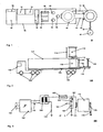
- Fig. 1 shows a plan view of the first test arrangement 50.
- the roof surface is not shown here, several test components of a test system 50 according to the invention are shown.
- Two inverter arrangements 54 are arranged in the front region, shown in the left-hand, of the first container, which are connected to a voltage supply of, for example, 400 V, 3-phase, 50 Hz, not shown.
- the respective connecting lines between the individual components are not shown in this illustration.
- each of the three AC voltages generated is transformed to a higher voltage level via the first test transformer 58 and fed to a test sample, not shown, with the respective voltages with voltage converters 62, 64, 66 demoulded to a lower, measurable voltage for measurement purposes are.
- the voltage transformers 62, 64, 66 have, for example, a height of about 1 m and are arranged, for example, such that the insulation distances within the first container 52 and to the container walls allow a maximum voltage of 220 kV. This voltage is sufficient for such 3-phase AC voltage tests.
- measuring evaluation devices 84 are provided, with which supplied measuring signals can be detected, stored and evaluated.
- a filter 56 is provided to smooth the AC voltages generated by the first inverter 54 if necessary.
- devices for reactive power compensation according to the invention can be arranged, the reactive power compensation can optionally also be done by the filter 56.
- a first high-voltage throttle 68, 70 is indicated in dashed form in the right inner region of the first container 52 in a first position. In this first position, the insulation distances necessary for the operation of the first high-voltage throttle 68, 70, for example, to the side walls of the first container 52 are not met. However, this first position within the first container 52 is suitable for transport purposes of the test arrangement.
- the first high-voltage throttle 68, 70 is connected in a resonant circuit with the test specimen.
- a resonance test takes place in a single-phase, so that only a single alternating voltage is generated by the first inverter 54 and only one high-voltage choke 68, 70 is required.
- the voltages that occur during a resonance test are often higher than those in a normal AC test, for example 500 kV, which is why the voltage transformers 62, 64, 66 are not suitable for direct use.
- the first high-voltage choke is now to be regarded in the second position 70, in which it was spent by means of the first movement device 72, for example an extendable telescopic rail.
- the first movement device 72 is by means of a Supporting device 80 against the footprint of the first container 52 is supported. An excessive buckling of the first movement device 72 is thereby avoided.
- a first voltage divider 86 is shown, which is electrically connected to the first high-voltage choke 70 via a connection 88.
- the first voltage divider 86 has not according to the invention been moved and connected manually from the first container 52 by means of a movement device.
- FIG. 2 shows a side view of second test arrangement 100.
- a second high-voltage throttle in a first position 108 is indicated by a dashed line within a second container 124, wherein this is preferably designed as a 40-foot container.
- the second container 124 is shown on a first 102 and a second 104 transport device with associated wheels 106, a truck with a semi-trailer. Due to the position within the boundaries of the second container 124, the second high-voltage throttle 108 is advantageously protected transported.
- the second container 124 is preferably closed at all six side walls during transport for protection purposes of the test arrangement.
- an opening is to be produced thereon through which the second high-voltage choke 108, 110 can be moved from the inside to the outside.
- at least one segment of the respective boundary wall to remove or move, preferably with a drive mechanism or manually.
- the second high-voltage throttle is shown in a second position 110 outside the second container 124.
- This second position can be reached from the first position by means of a second movement device 112, for example a lifting device.
- the direction of movement is perpendicular in the illustrated figure and is indicated by the arrow 114. But it is also a direction of movement of the high-voltage throttle in the horizontal direction by a side or end face of the container 124 conceivable.
- a second voltage divider in an inner position 120 and an outer position 122 is also shown.
- the direction of movement in the illustrated Fig. Horizontal and is marked with the arrow 118. But it is also a direction of movement of the second voltage divider 120, 122 in the vertical direction through the roof surface of the second container 124 conceivable.
- Fig. 3 shows a schematic overview diagram of a resonant circuit 150, to which a part of the test components for tests with particularly high voltages is interconnectable.
- a resonant circuit is single-phase, ie where in Fig. 1
- 3-phase indicated test components such as test transformer or voltage transformers only one phase is used in this arrangement.
- An inverter 152 is connected via its inputs 154 3-phase with a power supply on site, for example, 400V, 50Hz.
- a regulated alternating voltage is applied, which is preferably smoothed with filters, not shown.
- the frequency of the AC voltage is controlled so that the resonant circuit is excited in its resonant frequency.
- the resonant circuit mainly comprises a third high voltage choke 160, a DUT 172, and a capacitive third voltage divider 162.
- test object 172 is a 3-phase power transformer whose low-side terminals are each connected to a ground 170 and whose upper-voltage-side terminals 174 are electrically connected in parallel to one another in the resonant circuit.
- voltages up to several 100 kV can be generated, which can be measured with the voltage divider 162 having the two capacitors 164 and 166.
- the voltage is the reference variable for the frequency control of the inverter 152.
Landscapes
- Physics & Mathematics (AREA)
- General Physics & Mathematics (AREA)
- Testing Relating To Insulation (AREA)
- Testing Electric Properties And Detecting Electric Faults (AREA)
- Measuring Instrument Details And Bridges, And Automatic Balancing Devices (AREA)
- X-Ray Techniques (AREA)
- Rectifiers (AREA)
Description
- Die Erfindung betrifft eine Prüfanordnung zur Wechselspannungsprüfung von elektrischen Hochspannungskomponenten mit wenigstens einem Wechselrichter, mit wenigstens einem Prüftransformator und mit wenigstens einer Hochspannungsdrossel als Prüfkomponenten, wobei wenigstens die genannten Prüfkomponenten in einem gemeinsamen quaderförmigen Behälter angeordnet sind.
- Es ist allgemein bekannt, dass Hochspannungskomponenten, wie beispielsweise Leistungstransformatoren, einem Alterungsprozess unterworfen sind, welcher insbesondere die elektrische Isolation betrifft. Von daher sind zur Sicherstellung eines fehlerfreien Betriebes eines elektrischen Energieverteilungsnetzes mit derartigen Hochspannungskomponenten in bestimmten Zeitintervallen Prüfungen, insbesondere der Leistungstransformatoren, sinnvoll. Eine derartige Prüfung ist auch nach einer Reparatur oder Wartung eines Transformators sinnvoll bzw. erforderlich. Derartige Prüfungen geben Aufschluss über den Zustand beispielsweise der Isolation und ermöglichen auch die Detektion anderer Fehler der betreffenden Hochspannungskomponente.
- Hochspannungskomponenten wie Leistungstransformatoren weisen ein sehr hohes Gewicht auf, je nach elektrischer Nennleistung auch über 100t. Ein Transport eines derartigen innerhalb eines elektrischen Energieverteilungsnetzes eingebauten Leistungstransformators in ein fest installiertes Prüffeld, in welchem dieser mittels einer Wechselspannungsprüfung geprüft werden könnte, ist aufgrund des hohen Transportaufwandes für den jeweiligen Leistungstransformator praktisch ausgeschlossen. Zudem ist in den seltensten Fällen genügend Redundanz in einem Energieverteilungsnetz vorhanden, dass ein Leistungstransformator ohne Beeinträchtigung des Netzbetriebes ausgebaut werden könnte.
- Aus diesem Grund erfolgen derartige Wechselspannungsprüfungen von Leistungstransformatoren zumeist vor Ort. Die Prüfanordnung mit Wechselspannungsgenerator sowie weiteren für die Prüfung benötigten Komponenten wie Hochspannungsdrossel, Spannungsteiler, Mess- und Auswertevorrichtungen wird in mehreren Baugruppen zu dem Ort, an dem sich der zu prüfende Leistungstransformator befindet, transportiert und dort zu einer Prüfanordnung montiert. Insbesondere die Hochspannungsdrossel, welche für eine Resonanzprüfung zur Bildung eines Resonanzschwingkreises mit dem Prüfling benötigt wird, kann mit einer Höhe von beispielsweise 2,5m und einem Innendurchmesser von beispielsweise 1m eine Prüfkomponente von beachtlicher Größe darstellen. Auch der Spannungsteiler, welcher zur Messung der hohen Spannungen von beispielsweise bis zu mehreren 100kV im Resonanzschwingkreis benötigt wird, ist eine Komponente mit ähnlicher Höhe.
- Bei der Durchführung einer Wechselspannungsprüfung ist darauf zu achten, dass die Komponenten der Prüfanordnung aufgrund der hohen auftretenden Spannungen einen genügend großen Abstand zueinander und zu angrenzendem Erdpotential aufweisen.
- So ist aus der Veröffentlichung "A mobile transformer test system based on a static frequency converter" (Winter et al 15th International Symposium on High Voltage Engineering, University of Lljubljana, Elektroinstitut Milan Vidmar, Lljubljana, Slovenia, August 27-31, 2007 ) bekannt, statische Prüfsysteme für die Wechselspannungsprüfung von Transformatoren auch mobil auszuführen In dem Dokument
US 6586671 ist eine mittels Tieflader transportierbare Schaltanordnung bekannt, welche auch transportierbare zugehörige elektrische Gerätschaften umfasst. - Nachteilig ist, dass die Montage der verschiedenen Baugruppen vor Ort mit einem erheblichen Zeitaufwand verbunden ist. Insbesondere die Positionierung und Montage einer Hochspannungsdrossel oder eines Spannungsteilers sind sehr zeitaufwändig.
- Ausgehend von diesem Stand der Technik ist es Aufgabe der Erfindung, eine Prüfanordnung anzugeben, welche einen geringeren Platzbedarf aufweisen und in einer verringerten Anzahl von Baugruppen transportierbar sind
- Diese Aufgabe wird erfindungsgemäß gelöst durch eine Prüfanordnung mit den im Anspruch 1 angegebenen Merkmalen.
- Demgemäß kennzeichnet sich die Prüfanordnung der eingangs genannten Art unter anderen dadurch, dass die wenigstens eine Hochspannungsdrossel mittels einer Bewegungsvorrichtung durch wenigstens eine Öffnung an einer Begrenzungsfläche des Behälters zumindest teilweise aus diesem bewegbar ist.
- Die Isolationsabstände zwischen der Hochspannungsdrossel und weiteren angrenzenden Komponenten beziehungsweise angrenzendem Erdpotential sind hierdurch vorteilhaft steigerbar. Somit ist bei einer ersten Anordnungsvariante der Hochspannungsdrossel innerhalb des Behälters eine besonders platzsparende Anordnung gegeben, welche den Transport der Prüfanordnung vereinfacht. Bei einer weiteren Anordnungsvariante der Hochspannungsdrossel außerhalb des Behälters sind die Isolationsabstände erhöht, was den Betrieb der Anordnung ermöglicht oder zumindest isolationstechnisch sicherer gestaltet. Der Wechsel zwischen den Anordnungsvarianten erfolgt durch die Bewegungsvorrichtung in besonders einfacher Form.
- In vorteilhafter Weise wird durch die kompakte Anordnung der Drossel innerhalb des Behälters ein Transport des Behälters und der in ihm angeordneten Komponenten der Prüfanordnung vereinfacht.
- In einer weiteren Ausgestaltung der Prüfanordnung ist ein Spannungsteiler durch wenigstens eine weitere Öffnung an einer Begrenzungsfläche des Behälters mittels einer weiteren Bewegungsvorrichtung zumindest teilweise aus diesem bewegbar.
- Ein Spannungsteiler, welcher vorzugsweise in einer Resonanzkreisverschaltung der Prüfanordnung verwendet wird, ist eine Komponente ähnlicher Höhe wie eine Hochspannungsdrossel mit ähnlichen isolationstechnischen Anforderungen. Die Platzvorteile, welche sich für eine aus dem Behälter bewegbare Hochspannungsdrossel ergeben, erschließen sich demgemäß auch für einen aus dem Behälter bewegbaren Spannungsteiler.
- In einer Variante der Prüfanordnung ist die wenigstens eine und/oder die wenigstens eine weitere Öffnung an jeweils einer senkrechten Begrenzungsfläche des Behälters befindlich und die Bewegungsvorrichtung und/oder die weitere Bewegungsvorrichtung wirkt vorwiegend in horizontaler Richtung.
- Somit ist ein horizontales Herausbewegen der Hochspannungsdrossel und/oder des Spannungswandlers zu einer Seite oder einer Stirnfläche des Behälters ermöglicht. Ein Beispiel für eine geeignete Bewegungsvorrichtung ist eine Teleskopschiene.
- In einer bevorzugten Ausgestaltung der erfindungsgemäßen Anordnung ist die horizontal wirkende Bewegungsvorrichtung beziehungsweise die weitere horizontal wirkende Bewegungsvorrichtung mit der zumindest teilweise aus dem Behälter bewegten Hochspannungsdrossel beziehungsweise dem Spannungsteiler nach unten mittels jeweils einer Abstützvorrichtung abstützbar. Eine derartige Abstützvorrichtung ist - ähnlich wie bei einem gegen Kippen zu sichernden mobilen Kran - beispielsweise eine in einem senkrechten Gewindekanal angeordnete Spindel, welche durch eine Drehbewegung derart längs des Gewindekanals bewegbar ist, dass sie eine Stütze zwischen der Bewegungsvorrichtung und dem Untergrund bildet. Es ist aber auch eine Vielzahl von weiteren dem Fachmann bekannten Ausführungsformen einer Abstützvorrichtung möglich.
- Die an der Aussenkante des Behälters wirkende maximale Drehmomentbelastung der jeweiligen Bewegungsvorrichtung ist dadurch reduziert und deren Konstruktion wird vereinfacht. Zudem steigt die Standsicherheit des Behälters.
- In einer Variante der Prüfanordnung ist die wenigstens eine beziehungsweise wenigstens eine weitere Öffnung an der oberen Begrenzungsfläche des Behälters befindlich und die Bewegungsvorrichtung wirkt vorwiegend in vertikaler Richtung. Somit ist ein vertikales Herausbewegen der Hochspannungsdrossel beziehungsweise des Spannungsteilers durch die Dachseite des Behälters ermöglicht. Ein Beispiel für eine geeignete jeweilige Bewegungsvorrichtung ist eine hydraulische Hebevorrichtung.
- Vorteilhafterweise ist die wenigstens eine und/oder wenigstens eine weitere Öffnung des Behälters verschließbar. Bei einem Transport des Behälters mit geschlossenen Öffnungen sind die in ihm befindlichen Komponenten der Prüfanordnung somit besser geschützt.
- In einer bevorzugten Ausgestaltung der Prüfanordnung sind die Bewegungsvorrichtung und/oder die weitere Bewegungsvorrichtung mit jeweils einem Antrieb versehen. Der Bewegungsvorgang wird dadurch vereinfacht.
- In einer vorteilhaften Ausgestaltung der Prüfanordnung ist der Behälter mit einer Transportvorrichtung verbunden, welche sie tragende Räder aufweist, beispielsweise mit einem LKW mit Auflieger. Der Transport der Prüfanordnung wird dadurch vereinfacht.
- Besonders bevorzugt ist in diesem Zusammenhang die Ausgestaltung des Behälters als Container mit Standardabmessung, beispielsweise als Container mit 40 Fuß Länge. Dieser ist in einer weiteren Variante gemäß CSC (Container Safety Convention) zugelassen und somit in jeder beliebigen Position innerhalb eines Containerstapels auf einem Containerschiff platzierbar. Hierdurch wird die Transportierbarkeit der Prüfanordnung noch weiter erhöht.
- In einer bevorzugten Ausführungsform der Prüfanordnung weist der Behälter an seinem ersten Ende einen innen liegenden Bereich auf, in welchem Messvorrichtungen und/oder Auswertevorrichtungen angeordnet sind.
- Eine Messvorrichtung ist beispielsweise dafür vorgesehen, den Spannungsverlauf während einer Wechselspannungsprüfung zu messen und zu erfassen, wobei eine mittels des Spannungsteilers auf ein niedriges Spannungsniveau reduzierte Spannung gemessen wird. Eine Auswertevorrichtung ist dafür vorgesehen, die gemessenen und erfassten Spannungswerte auszuwerten und beispielsweise eine Aussage über den Zustand der Isolation der geprüften Hochspannungskomponente, beispielsweise einem Leistungstransformator, zu geben.
- In einer bevorzugten Ausführungsform der Prüfanordnung sind die Prüfkomponenten zumindest teilweise mittels isolierter Hochspannungskabel elektrisch miteinander verbunden. Der aus Isolationsgründen bedingte Mindestabstand zwischen den Prüfkomponenten ist dadurch weiter reduzierbar.
- In einer weiteren Ausführungsform der erfindungsgemäßen Prüfanordnung umfasst diese einen elektrischen Resonanzschwingkreis mit wenigstens der Hochspannungsdrossel und einer zu prüfenden Hochspannungskomponente sowie den damit verschalteten Spannungsteiler.
- Ein Resonanzschwingkreis ist eine einfache Möglichkeit, hohe Prüfspannungen zu erzeugen. Aufgrund der Höhe der erzeugten Prüfspannungen von beispielsweise 500kV beträgt die isolationstechnisch erforderliche Länge eines entsprechenden Spannungsteilers typischerweise etwa 2,5m, wie dem Fachmann jedoch bekannt ist. Diese Länge entspricht in etwa auch der Länge einer bevorzugten Ausführungsform einer erfindungsgemäßen Hochspannungsdrossel, welche beispielsweise einen lichten Innendurchmesser von ca. 1 m aufweist.
- Erfindungsgemäß ist der Resonanzschwingkreis mittels des Wechselrichters und des mit diesem elektrisch verbundenen Prüftransformators anregbar. Die elektrische Leistung eines derartigen Wechselrichters beträgt beispielsweise mehrere 100kVA . Der Wechselrichter erzeugt eine Wechselspannung variabler Frequenz, wobei diese auf die Resonanzfrequenz des Schwingkreises geregelt ist. Diese ist zunächst von der Kapazität bzw. Induktivität des Prüflings abhängig, aber auch von der Induktivität der Hochspannungsdrossel und der Kapazität des Spannungsteilers. Die Prüfkomponenten sind derart zu bemessen, dass die Resonanzfrequenz bei typischen Prüflingen ca. 100Hz nicht übersteigt.
- In einer weiteren Variante der Prüfanordnung weist die Hochspannungsdrossel wenigstens einen elektrischen Leiter auf, welcher in einer Vielzahl von Windungen um eine Wickelachse angeordnet ist, wobei die Windungen radial einen Innenraum längs der Wickelachse umschließen, wobei in diesem Innenraum wenigstens ein Kondensator angeordnet ist, durch welchen zusammen mit wenigstens einem weiteren mit diesem elektrisch verbundenen Kondensator die Funktionalität des Spannungsteilers gebildet ist.
- Bei einer derartigen Anordnung sind insbesondere isolationstechnische Anforderungen zwischen der Wicklung der Hochspannungsdrossel und dem innen angeordneten Kondensator zu erfüllen. Demgemäß ist es zweckmäßig, einen Wickelkörper, um den die Windungen der Hochspannungsdrossel üblicherweise angeordnet sind, in einem Isolationsmaterial von hinreichender Dicke, je nach Spannungsbeanspruchung beispielsweise einige Zentimeter, auszuführen.
- Die Anordnung eines Kondensators im Innenraum einer Hochspannungsdrossel, beispielsweise als Bestandteil eines Spannungsteilers, nutzt in vorteilhafter Weise den dort zur Verfügung stehenden Platz.
- In einer weiteren Ausgestaltung der Prüfanordnung ist wenigstens ein während eines Prüfvorgangs notwendiger Verfahrensschritt oder der gesamte Prüfvorgang mittels einer Fernbedienung initiierbar. Die Verwendung einer Fernbedienung reduziert den benötigten Montageaufwand für die Prüfanordnung in vorteilhafter Weise und ermöglicht zudem eine einfachere Durchführung einer Wechselspannungsprüfung.
- Weitere vorteilhafte Ausgestaltungsmöglichkeiten sind den weiteren abhängigen Ansprüchen zu.entnehmen.
- Anhand der in den Zeichnungen dargestellten Ausführungsbeispiele sollen die Erfindung, weitere Ausführungsformen und weitere Vorteile näher beschrieben werden.
- Es zeigen:
- Fig. 1
- eine Draufsicht auf erste Prüfanordnung,
- Fig. 2
- eine Seitenansicht auf zweite Prüfanordnung sowie
- Fig. 3
- ein Übersichtsbild eines Resonanzschwingkreises
-
Fig. 1 zeigt eine Draufsicht auf erste Prüfanordnung 50. Auf der Bodenfläche eines quaderförmigen ersten Behälters 52, dessen Dachfläche hier nicht gezeigt ist, sind mehrere Prüfkomponenten eines erfindungsgemäßen Prüfsystems 50 dargestellt. - Zwei Wechselrichteranordnungen 54 sind im vorderen, in der Fig. links dargestellten, Bereich des ersten Behälters angeordnet, welche mit einer nicht gezeigten Spannungsversorgung von beispielsweise 400V, 3phasig, 50 Hz verbunden sind. Die jeweiligen Verbindungsleitungen zwischen den einzelnen Komponenten sind in dieser Darstellung nicht gezeigt.
- Im Falle einer 3-phasigen Wechselspannungsprüfung wird jede der drei erzeugten Wechselspannungen über den ersten Prüftransformator 58 auf ein höheres Spannungsniveau transformiert und einem nicht gezeigten Prüfling zugeführt, wobei die jeweiligen Spannungen mit Spannungwandlern 62, 64, 66 zu Messzwecken auf eine niedrigere, messbare Spannung herunterformbar sind. Die Spannungswandler 62, 64, 66 haben beispielsweise eine Höhe von ca. 1m und sind beispielsweise derart angeordnet, dass die Isolationsabstände innerhalb des ersten Behälters 52 und zu den Behälterwänden eine maximale Spannung von 220kV zulassen. Diese Spannung ist für derartige 3-phasige Wechselspannungsprüfungen hinreichend. Im Messraum 82 im linken dargestellten Bereich des ersten Behälters 52 sind Mess- Auswertevorrichtungen 84 vorgesehen, mit welchen zugeführte Messsignale erfasst, gespeichert und ausgewertet werden können. Ein Filter 56 ist dafür vorgesehen, die vom ersten Wechselrichter 54 erzeugten Wechselspannungen gegebenenfalls zu glätten. Weiterhin sind auch Vorrichtungen zur Blindleistungskompensation erfindungsgemäß anordenbar, wobei die Blindleistungskompensation gegebenenfalls auch durch den Filter 56 erfolgen kann.
- Eine erste Hochspannungsdrossel 68, 70 ist in gestrichelter Form im rechten inneren Bereich des ersten Behälters 52 in einer ersten Position angedeutet. In dieser ersten Position sind die für den Betrieb der ersten Hochspannungsdrossel 68, 70 notwendigen Isolationsabstände, beispielsweise zu den Seitenwänden des ersten Behälters 52 nicht eingehalten. Diese erste Position innerhalb des ersten Behälters 52 ist aber für Transportzwecke der Prüfanordnung geeignet.
- Im Falle einer Resonanzprüfung wird die erste Hochspannungsdrossel 68, 70 in einem Resonanzschwingkreis mit dem Prüfling verschaltet. Eine Resonanzprüfung erfolgt 1-phasig, es wird also nur eine einzige Wechselspannung vom ersten Wechselrichter 54 erzeugt und es wird nur eine Hochspannungsdrossel 68, 70 benötigt. Die bei einer Resonanzprüfung auftretenden Spannungen sind oftmals höher, als die bei einer normalen Wechselspannungsprüfung, beispielsweise 500kV, weshalb die Spannungswandler 62, 64, 66 nicht zur direkten Verwendung geeignet sind.
- Die erste Hochspannungsdrossel ist nunmehr in der zweiten Position 70 anzusehen, in welche sie mittels der ersten Bewegungsvorrichtung 72 verbracht wurde, beispielsweise einer ausfahrbaren Teleskopschiene. Die erste Bewegungsvorrichtung 72 ist mittels einer Stützvorrichtung 80 gegenüber der Standfläche des ersten Behälters 52 abgestützt. Eine überhöhte Knickbeanspruchung der ersten Bewegungsvorrichtung 72 ist dadurch vermieden. Neben der ausgefahrenen ersten Hochspannungsdrossel 70 ist ein erster Spannungsteiler 86 dargestellt, welcher über eine Verbindung 88 elektrisch mit der ersten Hochspannungsdrossel 70 verbunden ist. In dieser Variante ist der erste Spannungsteiler 86 nicht erfindungsgemäß mittels einer Bewegungsvorrichtung sondern manuell aus dem ersten Behälter 52 verbracht und angeschlossen worden.
-
Fig. 2 zeigt eine Seitenansicht auf zweite Prüfanordnung 100. Eine zweite Hochspannungsdrossel in einer ersten Position 108 ist mit einer gestrichelten Linie innerhalb eines zweiten Behälters 124 angedeutet, wobei dieser vorzugsweise als 40-Fuß Container ausgeführt ist. Der zweite Behälter 124 ist auf einer ersten 102 und einer zweiten 104 Transportvorrichtung mit dazugehörigen Rädern 106 dargestellt, einem LKW mit einem Auflieger. Durch die Position innerhalb der Begrenzungen des zweiten Behälters 124 ist die zweite Hochspannungsdrossel 108 vorteilhaft geschützt transportierbar. Der zweite Behälter 124 ist beim Transport zu Schutzzwecken der Prüfanordnung vorzugsweise an allen sechs Seitenwänden verschlossen. Vor einem Bewegungsvorgang der zweiten Hochspannungsdrossel 108, 110 durch die äußere Begrenzung des zweiten Behälters 124 ist an diesem demgemäß zuvor eine Öffnung herzustellen, durch welche die zweite Hochspannungsdrossel 108, 110 von innen nach außen bewegbar ist. Hiezu ist wenigstens ein Segment der betreffenden Begrenzungswand zu entfernen oder zu verschieben, vorzugsweise mit einem Antriebsmechanismus oder aber auch manuell. - Weiterhin dargestellt ist die zweite Hochspannungsdrossel in einer zweiten Position 110 außerhalb des zweiten Behälters 124. Diese zweite Position ist von der ersten Position mittels einer zweiten Bewegungsvorrichtung 112, beispielsweise einer Hubvorrichtung, erreichbar. Die Bewegungsrichtung verläuft in der dargestellten Fig. senkrecht und ist mit dem Pfeil 114 gekennzeichnet. Es ist aber auch eine Bewegungsrichtung der Hochspannungsdrossel in horizontaler Richtung durch eine Seiten- oder Stirnfläche des Behälters 124 denkbar.
- Analog zur zweiten Hochspannungsdrossel 108, 110 ist auch ein zweiter Spannungsteiler in einer inneren Position 120 und einer äußeren Position 122 dargestellt. Die Bewegungsrichtung verläuft in der dargestellten Fig. waagerecht und ist mit dem Pfeil 118 gekennzeichnet. Es ist aber auch eine Bewegungsrichtung des zweiten Spannungsteilers 120, 122 in vertikaler Richtung durch die Dachfläche des zweiten Behälters 124 denkbar.
-
Fig. 3 zeigt ein schematisches Übersichtsschaltbild über einen Resonanzschwingkreis 150, zu welchem ein Teil der Prüfkomponenten für Prüfungen mit besonders hohen Spannungen zusammenschaltbar ist. Ein derartiger Resonanzschwingkreis ist einphasig, d.h. bei denen inFig. 1 teilweise 3-phasig angedeuteten Prüfkomponenten wie Prüftransformator oder Spannungswandlern wird in dieser Anordnung jeweils nur-eine Phase benutzt. - Ein Wechselrichter 152 ist über seine Eingänge 154 3-phasig mit einer Spannungsversorgung vor Ort verbunden, beispielsweise 400V, 50Hz. An den Ausgängen 156 des Wechselrichters 152, welche mit den Anschlüssen der Unterspannungsseite eines zweiten Prüftransformators 158 verbunden sind, liegt während des Betriebes eine geregelte Wechselspannung an, welche vorzugsweise mit nicht dargestellten Filtern geglättet wird. Die Frequenz der Wechselspannung ist derart geregelt, dass der Resonanzschwingkreis in seiner Resonanzfrequenz angeregt wird. Der Resonanzschwingkreis weist in der Hauptsache eine dritte Hochspannungsdrossel 160, einen Prüfling 172 und einen kapazitiven dritten Spannungsteiler 162 auf. Die Komponenten sind derart aufeinander abgestimmt, dass sich eine Resonanzfrequenz von etwas über den üblichen 50Hz Netzfrequenz ergibt, beispielsweise 150Hz, wobei diese insbesondere von den Kenndaten des zu testenden Prüflings abhängt. Der Prüfling 172 ist in der dargestellten Fig. ein 3-phasiger Leistungstransformator, dessen unterspannungsseitigen Anschlüsse jeweils mit einer Erdung 170 verbunden sind und dessen oberspannungsseitigen Anschlüsse 174 elektrisch parallel zueinander im Schwingkreis verschaltet sind.
- In einer derartigen Anordnung sind Spannungen bis zu mehreren 100kV erzeugbar, welche mit dem die beiden Kondensatoren 164 und 166 aufweisenden Spannungsteiler 162 messbar sind. Die Spannung ist Führungsgröße für die Frequenzregelung des Wechselrichters 152.
-
- 50
- Draufsicht auf erste Prüfanordnung
- 52
- erster Behälter
- 54
- erster Wechselrichter
- 56
- Filter
- 58
- erster Prüftransformator
- 60
- Anschlüsse Prüftransformator
- 62
- erster Spannungswandler
- 64
- zweiter Spannungswandler
- 66
- dritter Spannungswandler
- 68
- erste Hochspannungsdrossel in erster Position
- 70
- erste Hochspannungsdrossel in zweiter Position
- 72
- erste Bewegungsvorrichtung
- 74
- erste Bewegungsrichtung
- 80
- Stützvorrichtung
- 82
- Messraum
- 84
- Mess- / Auswertevorrichtung
- 86
- erster Spannungsteiler
- 88
- Verbindung
- 100
- Seitenansicht auf zweite Prüfanordnung
- 102
- erste Transportvorrichtung
- 104
- zweite Transportvorrichtung
- 106
- Rad
- 108
- zweite Hochspannungsdrossel in erster Position
- 110
- zweite Hochspannungsdrossel in zweiter Position
- 112
- zweite Bewegungsvorrichtung
- 114
- zweite Bewegungsrichtung
- 116
- dritte Bewegungsvorrichtung
- 118
- dritte Bewegungsrichtung
- 120
- zweiter Spannungsteiler in erster Position
- 122
- zweiter Spannungsteiler in zweiter Position
- 124
- zweiter Behälter
- 150
- Übersichtsbild Resonanzschwingkreis
- 152
- zweiter Wechselrichter
- 154
- Eingänge des zweiten Wechselrichters
- 156
- Ausgänge des zweiten Wechselrichters
- 158
- zweiter Prüftransformator
- 160
- dritte Hochspannungsdrossel
- 162
- dritter Spannungsteiler
- 164
- vierter Kondensator
- 166
- fünfter Kondensator
- 168
- Messspannung
- 170
- Erdung
- 172
- Leistungstransformator
- 174
- kurzgeschlossene oberspannungsseitige Anschlüsse
- 176
- kurzgeschlossene unterspannungsseitige Anschlüsse
Claims (14)
- Prüfanordnung (50, 100) zur Wechselspannungsprüfung von elektrischen Hochspannungskomponenten (172), umfassend• wenigstens einen Wechselrichter (54, 152), wenigstens einen Prüftransformator (58, 158) und wenigstens eine Hochspannungsdrossel (68, 70, 108, 114, 160) als Prüfkomponenten,• einen gemeinsamen quaderförmigen Behälter (52,124), in welchem wenigstens die genannten Prüfkomponenten angeordnet sind,• eine Bewegungsvorrichtung (72, 112),wobei
die wenigstens eine Hochspannungsdrossel (68,70, 108, 110, 160) mittels der Bewegungsvorrichtung (72, 112) durch wenigstens eine Öffnung an einer Begrenzungsfläche des Behälters (52, 124) zumindest teilweise aus diesem bewegbar ist und dadurch ein Wechsel zwischen einer ersten Anordnungsvariante der Hochspannungsdrossel (68, 70, 108,114,160) innerhalb des quaderförmigen Behälters (52,124) und einer zweiten Anordnungsvariante mit einem genügendem Isolationsabstand zur Durchführung der Wechselspannungsprüfung ermöglicht ist,
dadurch gekennzeichnet, dass diese eine weitere Bewegungsvorrichtung (116) und einen Spannungsteiler (86, 122, 162) umfasst, welcher durch wenigstens eine weitere Öffnung an einer Begrenzungsfläche des Behälters (52, 124) mittels der weiteren Bewegungsvorrichtung (116) zumindest teilweise aus diesem bewegbar ist. - Prüfanordnung nach Anspruche 1, dadurch gekennzeichnet, dass die wenigstens eine und/oder die wenigstens eine weitere Öffnung an jeweils einer senkrechten Begrenzungsfläche des Behälters (52, 124) befindlich ist und die Bewegungsvorrichtung (72,112) und/oder die weitere Bewegungsvorrichtung (116) vorwiegend in horizontaler Richtung (74, 116) wirkt.
- Prüfanordnung nach Anspruch 2, dadurch gekennzeichnet, dass die Bewegungsvorrichtung (72,112) und/oder die weitere Bewegungsvorrichtung (116) mit der zumindest teilweise aus dem Behälter (52, 124) bewegten Hochspannungsdrossel (68,70,108, 110,160) beziehungsweise mit dem zumindest teilweise aus dem Behälter bewegten Spannungsteiler (86,122,162) nach unten mittels einer Stützvorrichtung (80) abstützbar ist.
- Prüfanordnung nach Anspruch 1, dadurch gekennzeichnet, dass die wenigstens eine Öffnung und/oder die wenigstens eine weitere Öffnung an der oberen Begrenzungsfläche des Behälters (52, 124) befindlich ist und die Bewegungsvorrichtung (72, 112) und/oder die weitere Bewegungsvorrichtung (116) vorwiegend in vertikaler Richtung (114) wirkt.
- Prüfanordnung nach einem der vorherigen Ansprüche, dadurch gekennzeichnet, dass die wenigstens eine Öffnung und/oder die wenigstens eine weitere Öffnung verschließbar ist.
- Prüfanordnung nach einem der vorherigen Ansprüche, dadurch gekennzeichnet, dass die Bewegungsvorrichtung (72,112) und/oder die weitere Bewegungsvorrichtung (116) mit einem Antrieb versehen ist.
- Prüfanordnung nach einem der vorherigen Ansprüche, dadurch gekennzeichnet, dass der Behälter (52, 124) mit einer Transportvorrichtung (102, 104) verbunden ist, welche ihn tragende Räder (106) aufweist.
- Prüfanordnung nach einem der vorherigen Ansprüche, dadurch gekennzeichnet, dass der Behälter (52, 124) ein transportierbarer Container mit Standardabmessungen ist.
- Prüfanordnung nach einem der vorherigen Ansprüche, dadurch gekennzeichnet, dass der Behälter (52, 124) einen innen liegenden Bereich (82) aufweist, in welchem Messvorrichtungen und/oder Auswertevorrichtungen (84) angeordnet sind.
- Prüfanordnung nach einem der vorherigen Ansprüche, dadurch gekennzeichnet, dass die Prüfkomponenten, (54, 56, 58, 62, 64, 66, 68, 70, 86, 108, 110, 120, 122, 152, 158, 160, 162) zumindest teilweise mittels isolierten Hochspannungskabeln elektrisch miteinander verbunden sind.
- Prüfanordnung nach einem der vorherigen Ansprüche, dadurch gekennzeichnet, dass diese einen elektrischen Resonanzschwingkreis (150) mit wenigstens der Hochspannungsdrossel (68, 70, 108, 110, 160) und einer zu prüfenden Hochspannungskomponente (172) sowie einen damit verschalteten Spannungsteiler (86,120, 122, 162) umfasst.
- Prüfanordnung nach Anspruch 1, dadurch gekennzeichnet, dass der Resonanzschwingkreis (100) mittels des Wechselrichters (54,152) und des mit diesem elektrisch verbundenen Prüftransformators (58,158) anregbar ist.
- Prüfanordnung nach einem der Ansprüche 1 oder 12, dadurch gekennzeichnet, dass die Hochspannungsdrossel (88, 70,108,114,180) wenigstens einen elektrischen Leiter aufweist, welcher in einer Vielzahl von Windungen um eine Wickelachse angeordnet ist, wobei die Windungen radial einen Innenraum längs der Winkelachse umschließen und dass in diesem Innenraum wenigstens ein Kondensator (164) angeordnet ist, durch welchen zusammen mit wenigstens einem weiteren mit diesem elektrisch verbundenen Kondensator (166) die Funktionalität des Spannungsteilers (162) gebildet ist.
- Prüfanordnung nach einem der vorangegangenen Ansprüche, dadurch gekennzeichnet, dass wenigstens ein während eines Prüfvorgangs notwendiger Verfahrensschritt oder der gesamte Prüfvorgang mittels einer Fernbedienung initiierbar ist.
Priority Applications (30)
| Application Number | Priority Date | Filing Date | Title |
|---|---|---|---|
| ES08010691.7T ES2371787T5 (es) | 2008-06-12 | 2008-06-12 | Conjunto de ensayo para un ensayo de corriente alterna de componentes eléctricos de alta tensión |
| EP08010691.7A EP2133704B2 (de) | 2008-06-12 | 2008-06-12 | Prüfanordnung zur Wechselspannungsprüfung von elektrischen Hochspannungskomponenten |
| AT08010691T ATE522817T1 (de) | 2008-06-12 | 2008-06-12 | Prüfanordnung zur wechselspannungsprüfung von elektrischen hochspannungskomponenten |
| EP09004940A EP2133888B1 (de) | 2008-06-12 | 2009-04-03 | Prüfanordnung zur Wechselspannungsprüfung von elektrischen Hochspannungskomponenten |
| AT09004940T ATE520133T1 (de) | 2008-06-12 | 2009-04-03 | Prüfanordnung zur wechselspannungsprüfung von elektrischen hochspannungskomponenten |
| UAA201014832A UA105179C2 (uk) | 2008-06-12 | 2009-04-06 | Випробувальна установка для випробування змінною напругою високовольтних електричних компонентів |
| CN200980122462.8A CN102057286B (zh) | 2008-06-12 | 2009-05-27 | 用于电高压元件的交变电压测试的测试布置 |
| EP09761392.1A EP2286254B2 (de) | 2008-06-12 | 2009-05-27 | Prüfanordnung zur wechselspannungsprüfung von elektrischen hochspannungskomponenten |
| AU2009256991A AU2009256991B9 (en) | 2008-06-12 | 2009-05-27 | Test arrangement for AC voltage testing of electrical high voltage components |
| UAA201014834A UA100158C2 (uk) | 2008-06-12 | 2009-05-27 | Випробувальна установка для випробування змінною напругою високовольтних електричних компонентів |
| PCT/EP2009/003756 WO2009149829A1 (de) | 2008-06-12 | 2009-05-27 | Prüfanordnung zur wechselspannungsprüfung von elektrischen hochspannungskomponenten |
| AT09761392T ATE521900T1 (de) | 2008-06-12 | 2009-05-27 | Prüfanordnung zur wechselspannungsprüfung von elektrischen hochspannungskomponenten |
| RU2011100159/28A RU2494410C2 (ru) | 2008-06-12 | 2009-05-27 | Система тестирования для испытания переменным напряжением электрических высоковольтных компонентов |
| CA2726427A CA2726427C (en) | 2008-06-12 | 2009-05-27 | Test arrangement for ac voltage testing of electrical high voltage components |
| BRPI0915158-3A BRPI0915158B1 (pt) | 2008-06-12 | 2009-05-27 | Conjunto de teste para teste de alta tensão de ca de componentes elétricos de alta tensão |
| ES09761392T ES2372013T3 (es) | 2008-06-12 | 2009-05-27 | Conjunto de ensayo para el ensayo de corriente alterna de componentes eléctricos de alta tensión. |
| RU2011100174/28A RU2497138C2 (ru) | 2008-06-12 | 2009-06-04 | Испытательная система для испытания переменным напряжением электрических высоковольтных компонентов |
| CN200980122461.3A CN102057283B (zh) | 2008-06-12 | 2009-06-04 | 用于电高压元件的交变电压测试的测试布置 |
| PCT/EP2009/003977 WO2009149857A1 (de) | 2008-06-12 | 2009-06-04 | Prüfanordnung zur wechselspannungsprüfung von elektrischen hochspannungskomponenten |
| BRPI0915110-9A BRPI0915110B1 (pt) | 2008-06-12 | 2009-06-04 | Disposição de teste para teste de tensão de ca dos componentes elétricos de alta tensão |
| PCT/EP2009/004001 WO2009149866A1 (de) | 2008-06-12 | 2009-06-04 | Prüfanordnung zur wechselspannungsprüfung von elektrischen hochspannungskomponenten |
| BRPI0915211A BRPI0915211A8 (pt) | 2008-06-12 | 2009-06-04 | Disposição de teste para testar ca de componentes elétricos de alta tensão |
| AU2009256936A AU2009256936A1 (en) | 2008-06-12 | 2009-06-04 | Test arrangement for AC testing of electrical high voltage components |
| CA2726437A CA2726437C (en) | 2008-06-12 | 2009-06-04 | Test arrangement for ac testing of electrical high voltage components |
| ARP090102141A AR072126A1 (es) | 2008-06-12 | 2009-06-12 | Disposicion de ensayo |
| SA109300379A SA109300379B1 (ar) | 2008-06-12 | 2009-06-13 | ترتيبة فحص تستخدم لفحص فلطية التيار المتناوب لمكوِّنات كهربائية مرتفعة الفلطية |
| US12/963,144 US8952704B2 (en) | 2008-06-12 | 2010-12-08 | Test arrangement for AC testing of electrical high voltage components |
| US12/963,044 US8427172B2 (en) | 2008-06-12 | 2010-12-08 | Test arrangement for AC testing of electrical high voltage components |
| US12/963,941 US8643381B2 (en) | 2008-06-12 | 2010-12-09 | Test arrangement for AC voltage testing of electrical high voltage components |
| AU2014203314A AU2014203314B2 (en) | 2008-06-12 | 2014-06-18 | Test arrangement for AC testing of electrical high voltage components |
Applications Claiming Priority (1)
| Application Number | Priority Date | Filing Date | Title |
|---|---|---|---|
| EP08010691.7A EP2133704B2 (de) | 2008-06-12 | 2008-06-12 | Prüfanordnung zur Wechselspannungsprüfung von elektrischen Hochspannungskomponenten |
Publications (3)
| Publication Number | Publication Date |
|---|---|
| EP2133704A1 EP2133704A1 (de) | 2009-12-16 |
| EP2133704B1 EP2133704B1 (de) | 2011-08-31 |
| EP2133704B2 true EP2133704B2 (de) | 2015-12-02 |
Family
ID=39960711
Family Applications (3)
| Application Number | Title | Priority Date | Filing Date |
|---|---|---|---|
| EP08010691.7A Not-in-force EP2133704B2 (de) | 2008-06-12 | 2008-06-12 | Prüfanordnung zur Wechselspannungsprüfung von elektrischen Hochspannungskomponenten |
| EP09004940A Revoked EP2133888B1 (de) | 2008-06-12 | 2009-04-03 | Prüfanordnung zur Wechselspannungsprüfung von elektrischen Hochspannungskomponenten |
| EP09761392.1A Active EP2286254B2 (de) | 2008-06-12 | 2009-05-27 | Prüfanordnung zur wechselspannungsprüfung von elektrischen hochspannungskomponenten |
Family Applications After (2)
| Application Number | Title | Priority Date | Filing Date |
|---|---|---|---|
| EP09004940A Revoked EP2133888B1 (de) | 2008-06-12 | 2009-04-03 | Prüfanordnung zur Wechselspannungsprüfung von elektrischen Hochspannungskomponenten |
| EP09761392.1A Active EP2286254B2 (de) | 2008-06-12 | 2009-05-27 | Prüfanordnung zur wechselspannungsprüfung von elektrischen hochspannungskomponenten |
Country Status (13)
| Country | Link |
|---|---|
| US (3) | US8952704B2 (de) |
| EP (3) | EP2133704B2 (de) |
| CN (2) | CN102057286B (de) |
| AR (1) | AR072126A1 (de) |
| AT (3) | ATE522817T1 (de) |
| AU (3) | AU2009256991B9 (de) |
| BR (3) | BRPI0915158B1 (de) |
| CA (2) | CA2726427C (de) |
| ES (2) | ES2371787T5 (de) |
| RU (2) | RU2494410C2 (de) |
| SA (1) | SA109300379B1 (de) |
| UA (2) | UA105179C2 (de) |
| WO (3) | WO2009149829A1 (de) |
Families Citing this family (21)
| Publication number | Priority date | Publication date | Assignee | Title |
|---|---|---|---|---|
| DE102007059289B4 (de) * | 2007-12-08 | 2011-07-28 | Maschinenfabrik Reinhausen GmbH, 93059 | Vorrichtung zur Prüfung von Transformatoren |
| EP2133704B2 (de) | 2008-06-12 | 2015-12-02 | ABB Technology AG | Prüfanordnung zur Wechselspannungsprüfung von elektrischen Hochspannungskomponenten |
| EP2133703B1 (de) | 2008-06-12 | 2011-10-12 | ABB Technology AG | Prüfanordnung zur Stossspannungsprüfung von elektrischen Hochspannungskomponenten |
| DE102009023713B4 (de) * | 2009-06-03 | 2014-06-05 | Maschinenfabrik Reinhausen Gmbh | Vorrichtung zur Prüfung von Geräten der Hochspannungstechnik |
| GB2480455B (en) * | 2010-05-18 | 2012-10-10 | Megger Instr Ltd | High voltage liquid dielectric test vessel |
| CN102285333B (zh) * | 2011-07-13 | 2012-10-03 | 苏州华电电气股份有限公司 | 超高压电力互感器校验车 |
| EP2590185B1 (de) * | 2011-11-02 | 2014-04-02 | ABB Technology AG | Hochspannungstransformatormodul |
| EP2590490B1 (de) | 2011-11-02 | 2014-01-08 | ABB Technology AG | Prüfcontainer |
| DE102012101548B4 (de) * | 2012-02-27 | 2015-11-19 | Maschinenfabrik Reinhausen Gmbh | Prüfsystem und Verfahren für eine induzierte Spannungsprüfung sowie Verlustleistungsmessung von Prüfobjekten der Hochspannungstechnik |
| ES2646437T3 (es) * | 2012-06-06 | 2017-12-13 | Prysmian S.P.A. | Sistema de derivación para líneas eléctricas aéreas |
| DE102012105045A1 (de) * | 2012-06-12 | 2013-12-12 | Maschinenfabrik Reinhausen Gmbh | Vorrichtung zum Kalibirieren eines Leistungsmesssystems für Leistungstransformatoren |
| EP3500024B1 (de) * | 2012-07-25 | 2025-09-17 | Sun Patent Trust | Basisstationsvorrichtung, endgerätevorrichtung, sendeverfahren und empfangsverfahren |
| CN102944775B (zh) * | 2012-10-30 | 2014-10-22 | 苏州华电电气股份有限公司 | 一种基于高压变频电源的大容量变压器特性试验系统 |
| ES2563109T3 (es) * | 2012-12-19 | 2016-03-10 | Abb Research Ltd. | Disposición de transformador para mitigar oscilaciones transitorias de la tensión |
| EP2853908B1 (de) | 2013-09-25 | 2021-03-31 | ABB Power Grids Switzerland AG | Prüfsystem für Hochspannungskomponenten |
| EP2863236B1 (de) * | 2013-10-18 | 2019-12-04 | ABB Schweiz AG | Prüfsystem für Hochspannungskomponenten |
| RU2659588C1 (ru) * | 2017-01-30 | 2018-07-03 | Илья Николаевич Джус | Инверторный испытатель трансформаторов |
| FR3074599B1 (fr) | 2017-12-05 | 2019-12-20 | Alstom Transport Technologies | Systeme de test d'un bloc de traction ferroviaire |
| RU2739702C1 (ru) * | 2019-12-02 | 2020-12-28 | Илья Николаевич Джус | Установка для испытания трансформаторов |
| US11876384B2 (en) * | 2020-12-15 | 2024-01-16 | Otis Elevator Company | Wireless power transfer device |
| WO2023106961A1 (ru) * | 2021-12-08 | 2023-06-15 | Федеральное Государственное Унитарное Предприятие "Российский Федеральный Ядерный Центр - Всероссийский Научно - Исследовательский Институт Технической Физики Имени Академика Е.И. Забабахина" | Мобильная высоковольтная установка для испытаний силовых трансформаторов |
Citations (3)
| Publication number | Priority date | Publication date | Assignee | Title |
|---|---|---|---|---|
| DE2328375A1 (de) † | 1973-06-04 | 1975-01-02 | Transformatoren Union Ag | Kondensatorbatterie zur spannungssteuerung an wicklungen von transformatoren und drosseln |
| US4427898A (en) † | 1981-12-22 | 1984-01-24 | Mitsubishi Denki Kabushiki Kaisha | Mobile power station apparatus |
| US4535253A (en) † | 1982-05-20 | 1985-08-13 | Mitsubishi Denki Kabushiki Kaisha | Mobile electrical apparatus |
Family Cites Families (21)
| Publication number | Priority date | Publication date | Assignee | Title |
|---|---|---|---|---|
| DE521475C (de) * | 1929-03-28 | 1931-03-21 | Koch & Sterzel Akt Ges | Transformator, insbesondere Messwandler, fuer hohe Spannungen, bestehend aus in Kaskade geschalteten Einzelsystemen mit in Reihe liegenden Primaerwicklungen und Schub- und UEberkopplungswicklungen |
| US2032904A (en) * | 1935-10-03 | 1936-03-03 | Westinghouse Electric & Mfg Co | Lightning-stroke generator |
| US2237812A (en) * | 1940-02-23 | 1941-04-08 | Gen Electric | Portable unit substation |
| US2551841A (en) * | 1946-11-27 | 1951-05-08 | Westinghouse Electric Corp | Electrical apparatus |
| DE1563442A1 (de) | 1966-12-08 | 1970-04-02 | Siemens Ag | Kurzschlussdrosselspule |
| AT330887B (de) | 1974-11-08 | 1976-07-26 | Leinweber Anstalt Ing Joh | Vorrichtung zum pressen von gekrümmten bremsbelägen |
| JPS5936091Y2 (ja) * | 1978-11-24 | 1984-10-05 | 株式会社明電舎 | 移動用変電設備 |
| SU1179234A1 (ru) | 1983-08-19 | 1985-09-15 | Проектно-конструкторское бюро электрогидравлики АН УССР | Устройство дл возбуждени сейсмических волн |
| JPS61102176A (ja) | 1984-10-24 | 1986-05-20 | Kansai Electric Power Co Inc:The | インパルス電圧発生装置 |
| JPH0738011B2 (ja) * | 1988-05-16 | 1995-04-26 | 株式会社日立製作所 | 高圧電力機器の異常診断システム |
| US5686697A (en) * | 1995-01-06 | 1997-11-11 | Metatech Corporation | Electrical circuit suspension system |
| RU2083824C1 (ru) * | 1995-06-13 | 1997-07-10 | Научно-исследовательский институт высоких напряжений при Томском политехническом университете | Способ разрушения горных пород |
| DE19639023A1 (de) | 1996-09-23 | 1998-03-26 | Haefely Trench Ag | Impulsspannungsgeneratorschaltung |
| US6313640B1 (en) * | 1998-02-03 | 2001-11-06 | Abb Power T & D Company, Inc. | System and method for diagnosing and measuring partial discharge |
| ATE405989T1 (de) * | 2000-12-20 | 2008-09-15 | Haefely Test Ag | Tragende kaminstruktur für elektrischen impulsgenerator |
| US6586697B1 (en) * | 2002-07-26 | 2003-07-01 | Pauwels Contracting Inc. | Transportable electrical switching assembly with high voltage circuit interrupter |
| US6586671B1 (en) | 2002-08-06 | 2003-07-01 | Interrail Signal, Inc. | Above ground track signal terminal apparatus |
| CN2574062Y (zh) * | 2002-10-17 | 2003-09-17 | 北京安控科技发展有限公司 | 电流信号调理电路 |
| RU2222858C1 (ru) * | 2002-10-31 | 2004-01-27 | Механошин Борис Иосифович | Устройство для дистанционного контроля состояния провода воздушной линии электропередачи (варианты) |
| EP2133704B2 (de) | 2008-06-12 | 2015-12-02 | ABB Technology AG | Prüfanordnung zur Wechselspannungsprüfung von elektrischen Hochspannungskomponenten |
| DE202009001837U1 (de) | 2009-02-13 | 2009-04-16 | Fachhochschule Flensburg | Mobiler Norm-Blitzstoßspannungsgenerator |
-
2008
- 2008-06-12 EP EP08010691.7A patent/EP2133704B2/de not_active Not-in-force
- 2008-06-12 AT AT08010691T patent/ATE522817T1/de active
- 2008-06-12 ES ES08010691.7T patent/ES2371787T5/es active Active
-
2009
- 2009-04-03 EP EP09004940A patent/EP2133888B1/de not_active Revoked
- 2009-04-03 AT AT09004940T patent/ATE520133T1/de active
- 2009-04-06 UA UAA201014832A patent/UA105179C2/uk unknown
- 2009-05-27 CN CN200980122462.8A patent/CN102057286B/zh active Active
- 2009-05-27 AU AU2009256991A patent/AU2009256991B9/en not_active Ceased
- 2009-05-27 UA UAA201014834A patent/UA100158C2/uk unknown
- 2009-05-27 EP EP09761392.1A patent/EP2286254B2/de active Active
- 2009-05-27 ES ES09761392T patent/ES2372013T3/es active Active
- 2009-05-27 CA CA2726427A patent/CA2726427C/en active Active
- 2009-05-27 BR BRPI0915158-3A patent/BRPI0915158B1/pt active IP Right Grant
- 2009-05-27 AT AT09761392T patent/ATE521900T1/de active
- 2009-05-27 RU RU2011100159/28A patent/RU2494410C2/ru active
- 2009-05-27 WO PCT/EP2009/003756 patent/WO2009149829A1/de not_active Ceased
- 2009-06-04 RU RU2011100174/28A patent/RU2497138C2/ru not_active IP Right Cessation
- 2009-06-04 CA CA2726437A patent/CA2726437C/en active Active
- 2009-06-04 CN CN200980122461.3A patent/CN102057283B/zh active Active
- 2009-06-04 AU AU2009256936A patent/AU2009256936A1/en not_active Abandoned
- 2009-06-04 BR BRPI0915110-9A patent/BRPI0915110B1/pt active IP Right Grant
- 2009-06-04 WO PCT/EP2009/004001 patent/WO2009149866A1/de not_active Ceased
- 2009-06-04 WO PCT/EP2009/003977 patent/WO2009149857A1/de not_active Ceased
- 2009-06-04 BR BRPI0915211A patent/BRPI0915211A8/pt not_active Application Discontinuation
- 2009-06-12 AR ARP090102141A patent/AR072126A1/es not_active Application Discontinuation
- 2009-06-13 SA SA109300379A patent/SA109300379B1/ar unknown
-
2010
- 2010-12-08 US US12/963,144 patent/US8952704B2/en active Active
- 2010-12-08 US US12/963,044 patent/US8427172B2/en active Active
- 2010-12-09 US US12/963,941 patent/US8643381B2/en not_active Expired - Fee Related
-
2014
- 2014-06-18 AU AU2014203314A patent/AU2014203314B2/en not_active Ceased
Patent Citations (3)
| Publication number | Priority date | Publication date | Assignee | Title |
|---|---|---|---|---|
| DE2328375A1 (de) † | 1973-06-04 | 1975-01-02 | Transformatoren Union Ag | Kondensatorbatterie zur spannungssteuerung an wicklungen von transformatoren und drosseln |
| US4427898A (en) † | 1981-12-22 | 1984-01-24 | Mitsubishi Denki Kabushiki Kaisha | Mobile power station apparatus |
| US4535253A (en) † | 1982-05-20 | 1985-08-13 | Mitsubishi Denki Kabushiki Kaisha | Mobile electrical apparatus |
Non-Patent Citations (4)
| Title |
|---|
| EKLUND L. ET AL.: "Increase transformer reliability and availability: From condition assessment to On-Site Repair", POWER-GEN MIDDLE EAST, April 2007 (2007-04-01), pages 1 - 17 † |
| EKLUND L. ET AL.: "Tranformation vor Ort", ABB TECHNIK, April 2007 (2007-04-01), pages 46 - 48 † |
| Ursprünglicher Dateiname: E6.pdf † |
| WINTER A. ET AL.: "A New Generation of On-Site Test Systems for Power Transformers", IEEE, 10 June 2008 (2008-06-10), pages 478 - 482 † |
Also Published As
Similar Documents
| Publication | Publication Date | Title |
|---|---|---|
| EP2133704B2 (de) | Prüfanordnung zur Wechselspannungsprüfung von elektrischen Hochspannungskomponenten | |
| EP2286255B1 (de) | Prüfanordnung zur Stossspannungsprüfung von elektrischen Hochspannungskomponenten | |
| EP2438450B1 (de) | Vorrichtung zur prüfung von geräten der hochspannungstechnik | |
| DE102017104110B4 (de) | Verfahren und Vorrichtung zur Verlustfaktorüberwachung von Kondensatordurchführungen | |
| EP3304097B1 (de) | Nullflussstromwandler | |
| EP3447507A1 (de) | Mobile teilentladung-prüfeinrichtung | |
| EP3589963B1 (de) | Verfahren und vorrichtung zur überwachung von kondensatordurchführungen für ein wechselstromnetz | |
| EP2863236B1 (de) | Prüfsystem für Hochspannungskomponenten | |
| EP2859374B1 (de) | Vorrichtung zum kalibrieren eines leistungsmesssystems für leistungstransformatoren | |
| EP2133889A1 (de) | Drossel und Prüfanordnung mit Drossel | |
| WO2013170870A2 (de) | Hochspannungstransformatormodul | |
| EP2947668B1 (de) | Stromkreisanordnung für eine Hochspannungsprüfanlage | |
| DE202008016238U1 (de) | Prüfanordnung | |
| DE202015007978U1 (de) | Mobile Transformatorstation mit Mast | |
| DE102012105054B4 (de) | Vorrichtung zur Leistungsmessung | |
| DE102023206512A1 (de) | Gehäuse für ein Hochspannungsgerät mit einem Aufnahmekanal für eine Sensoreinrichtung |
Legal Events
| Date | Code | Title | Description |
|---|---|---|---|
| PUAI | Public reference made under article 153(3) epc to a published international application that has entered the european phase |
Free format text: ORIGINAL CODE: 0009012 |
|
| AK | Designated contracting states |
Kind code of ref document: A1 Designated state(s): AT BE BG CH CY CZ DE DK EE ES FI FR GB GR HR HU IE IS IT LI LT LU LV MC MT NL NO PL PT RO SE SI SK TR |
|
| AX | Request for extension of the european patent |
Extension state: AL BA MK RS |
|
| 17P | Request for examination filed |
Effective date: 20100511 |
|
| 17Q | First examination report despatched |
Effective date: 20100608 |
|
| AKX | Designation fees paid |
Designated state(s): AT BE BG CH CY CZ DE DK EE ES FI FR GB GR HR HU IE IS IT LI LT LU LV MC MT NL NO PL PT RO SE SI SK TR |
|
| RIN1 | Information on inventor provided before grant (corrected) |
Inventor name: WERLE,PETER Inventor name: WOHLFAHRT, JUERGEN, DIPL.-ING. Inventor name: STEIGER, MATTHIAS |
|
| RIN1 | Information on inventor provided before grant (corrected) |
Inventor name: WERLE,PETER Inventor name: WOHLFARTH, JUERGEN, DIPL.-ING. Inventor name: STEIGER, MATTHIAS |
|
| GRAP | Despatch of communication of intention to grant a patent |
Free format text: ORIGINAL CODE: EPIDOSNIGR1 |
|
| RTI1 | Title (correction) |
Free format text: TEST ASSEMBLY FOR AC TESTING OF HIGH VOLTAGE ELECTRICAL COMPONENTS |
|
| RIN1 | Information on inventor provided before grant (corrected) |
Inventor name: WERLE PETER Inventor name: WOHLFARTH, JUERGEN Inventor name: STEIGER, MATTHIAS |
|
| GRAS | Grant fee paid |
Free format text: ORIGINAL CODE: EPIDOSNIGR3 |
|
| GRAA | (expected) grant |
Free format text: ORIGINAL CODE: 0009210 |
|
| AK | Designated contracting states |
Kind code of ref document: B1 Designated state(s): AT BE BG CH CY CZ DE DK EE ES FI FR GB GR HR HU IE IS IT LI LT LU LV MC MT NL NO PL PT RO SE SI SK TR |
|
| REG | Reference to a national code |
Ref country code: GB Ref legal event code: FG4D Free format text: NOT ENGLISH Ref country code: CH Ref legal event code: EP |
|
| REG | Reference to a national code |
Ref country code: IE Ref legal event code: FG4D Free format text: LANGUAGE OF EP DOCUMENT: GERMAN |
|
| REG | Reference to a national code |
Ref country code: DE Ref legal event code: R096 Ref document number: 502008004643 Country of ref document: DE Effective date: 20111027 |
|
| REG | Reference to a national code |
Ref country code: NL Ref legal event code: VDEP Effective date: 20110831 |
|
| REG | Reference to a national code |
Ref country code: ES Ref legal event code: FG2A Ref document number: 2371787 Country of ref document: ES Kind code of ref document: T3 Effective date: 20120110 |
|
| LTIE | Lt: invalidation of european patent or patent extension |
Effective date: 20110831 |
|
| PG25 | Lapsed in a contracting state [announced via postgrant information from national office to epo] |
Ref country code: FI Free format text: LAPSE BECAUSE OF FAILURE TO SUBMIT A TRANSLATION OF THE DESCRIPTION OR TO PAY THE FEE WITHIN THE PRESCRIBED TIME-LIMIT Effective date: 20110831 Ref country code: NO Free format text: LAPSE BECAUSE OF FAILURE TO SUBMIT A TRANSLATION OF THE DESCRIPTION OR TO PAY THE FEE WITHIN THE PRESCRIBED TIME-LIMIT Effective date: 20111130 Ref country code: NL Free format text: LAPSE BECAUSE OF FAILURE TO SUBMIT A TRANSLATION OF THE DESCRIPTION OR TO PAY THE FEE WITHIN THE PRESCRIBED TIME-LIMIT Effective date: 20110831 Ref country code: HR Free format text: LAPSE BECAUSE OF FAILURE TO SUBMIT A TRANSLATION OF THE DESCRIPTION OR TO PAY THE FEE WITHIN THE PRESCRIBED TIME-LIMIT Effective date: 20110831 Ref country code: IS Free format text: LAPSE BECAUSE OF FAILURE TO SUBMIT A TRANSLATION OF THE DESCRIPTION OR TO PAY THE FEE WITHIN THE PRESCRIBED TIME-LIMIT Effective date: 20111231 Ref country code: LT Free format text: LAPSE BECAUSE OF FAILURE TO SUBMIT A TRANSLATION OF THE DESCRIPTION OR TO PAY THE FEE WITHIN THE PRESCRIBED TIME-LIMIT Effective date: 20110831 Ref country code: SE Free format text: LAPSE BECAUSE OF FAILURE TO SUBMIT A TRANSLATION OF THE DESCRIPTION OR TO PAY THE FEE WITHIN THE PRESCRIBED TIME-LIMIT Effective date: 20110831 |
|
| PG25 | Lapsed in a contracting state [announced via postgrant information from national office to epo] |
Ref country code: CY Free format text: LAPSE BECAUSE OF FAILURE TO SUBMIT A TRANSLATION OF THE DESCRIPTION OR TO PAY THE FEE WITHIN THE PRESCRIBED TIME-LIMIT Effective date: 20110831 Ref country code: GR Free format text: LAPSE BECAUSE OF FAILURE TO SUBMIT A TRANSLATION OF THE DESCRIPTION OR TO PAY THE FEE WITHIN THE PRESCRIBED TIME-LIMIT Effective date: 20111201 Ref country code: LV Free format text: LAPSE BECAUSE OF FAILURE TO SUBMIT A TRANSLATION OF THE DESCRIPTION OR TO PAY THE FEE WITHIN THE PRESCRIBED TIME-LIMIT Effective date: 20110831 Ref country code: SI Free format text: LAPSE BECAUSE OF FAILURE TO SUBMIT A TRANSLATION OF THE DESCRIPTION OR TO PAY THE FEE WITHIN THE PRESCRIBED TIME-LIMIT Effective date: 20110831 |
|
| REG | Reference to a national code |
Ref country code: IE Ref legal event code: FD4D |
|
| PG25 | Lapsed in a contracting state [announced via postgrant information from national office to epo] |
Ref country code: IE Free format text: LAPSE BECAUSE OF FAILURE TO SUBMIT A TRANSLATION OF THE DESCRIPTION OR TO PAY THE FEE WITHIN THE PRESCRIBED TIME-LIMIT Effective date: 20110831 Ref country code: CZ Free format text: LAPSE BECAUSE OF FAILURE TO SUBMIT A TRANSLATION OF THE DESCRIPTION OR TO PAY THE FEE WITHIN THE PRESCRIBED TIME-LIMIT Effective date: 20110831 Ref country code: SK Free format text: LAPSE BECAUSE OF FAILURE TO SUBMIT A TRANSLATION OF THE DESCRIPTION OR TO PAY THE FEE WITHIN THE PRESCRIBED TIME-LIMIT Effective date: 20110831 |
|
| PG25 | Lapsed in a contracting state [announced via postgrant information from national office to epo] |
Ref country code: PL Free format text: LAPSE BECAUSE OF FAILURE TO SUBMIT A TRANSLATION OF THE DESCRIPTION OR TO PAY THE FEE WITHIN THE PRESCRIBED TIME-LIMIT Effective date: 20110831 Ref country code: EE Free format text: LAPSE BECAUSE OF FAILURE TO SUBMIT A TRANSLATION OF THE DESCRIPTION OR TO PAY THE FEE WITHIN THE PRESCRIBED TIME-LIMIT Effective date: 20110831 Ref country code: RO Free format text: LAPSE BECAUSE OF FAILURE TO SUBMIT A TRANSLATION OF THE DESCRIPTION OR TO PAY THE FEE WITHIN THE PRESCRIBED TIME-LIMIT Effective date: 20110831 Ref country code: PT Free format text: LAPSE BECAUSE OF FAILURE TO SUBMIT A TRANSLATION OF THE DESCRIPTION OR TO PAY THE FEE WITHIN THE PRESCRIBED TIME-LIMIT Effective date: 20120102 |
|
| PLBI | Opposition filed |
Free format text: ORIGINAL CODE: 0009260 |
|
| PG25 | Lapsed in a contracting state [announced via postgrant information from national office to epo] |
Ref country code: DK Free format text: LAPSE BECAUSE OF FAILURE TO SUBMIT A TRANSLATION OF THE DESCRIPTION OR TO PAY THE FEE WITHIN THE PRESCRIBED TIME-LIMIT Effective date: 20110831 |
|
| PLAX | Notice of opposition and request to file observation + time limit sent |
Free format text: ORIGINAL CODE: EPIDOSNOBS2 |
|
| 26 | Opposition filed |
Opponent name: HIGHVOLT PRUEFTECHNIK DRESDEN GMBH Effective date: 20120530 |
|
| REG | Reference to a national code |
Ref country code: DE Ref legal event code: R026 Ref document number: 502008004643 Country of ref document: DE Effective date: 20120530 |
|
| PLBB | Reply of patent proprietor to notice(s) of opposition received |
Free format text: ORIGINAL CODE: EPIDOSNOBS3 |
|
| BERE | Be: lapsed |
Owner name: ABB TECHNOLOGY A.G. Effective date: 20120630 |
|
| PG25 | Lapsed in a contracting state [announced via postgrant information from national office to epo] |
Ref country code: MC Free format text: LAPSE BECAUSE OF NON-PAYMENT OF DUE FEES Effective date: 20120630 |
|
| REG | Reference to a national code |
Ref country code: CH Ref legal event code: PL |
|
| REG | Reference to a national code |
Ref country code: CH Ref legal event code: PL |
|
| PG25 | Lapsed in a contracting state [announced via postgrant information from national office to epo] |
Ref country code: LI Free format text: LAPSE BECAUSE OF NON-PAYMENT OF DUE FEES Effective date: 20120630 Ref country code: BE Free format text: LAPSE BECAUSE OF NON-PAYMENT OF DUE FEES Effective date: 20120630 Ref country code: CH Free format text: LAPSE BECAUSE OF NON-PAYMENT OF DUE FEES Effective date: 20120630 |
|
| PG25 | Lapsed in a contracting state [announced via postgrant information from national office to epo] |
Ref country code: BG Free format text: LAPSE BECAUSE OF FAILURE TO SUBMIT A TRANSLATION OF THE DESCRIPTION OR TO PAY THE FEE WITHIN THE PRESCRIBED TIME-LIMIT Effective date: 20111130 |
|
| PG25 | Lapsed in a contracting state [announced via postgrant information from national office to epo] |
Ref country code: MT Free format text: LAPSE BECAUSE OF FAILURE TO SUBMIT A TRANSLATION OF THE DESCRIPTION OR TO PAY THE FEE WITHIN THE PRESCRIBED TIME-LIMIT Effective date: 20110831 |
|
| PG25 | Lapsed in a contracting state [announced via postgrant information from national office to epo] |
Ref country code: TR Free format text: LAPSE BECAUSE OF FAILURE TO SUBMIT A TRANSLATION OF THE DESCRIPTION OR TO PAY THE FEE WITHIN THE PRESCRIBED TIME-LIMIT Effective date: 20110831 |
|
| PG25 | Lapsed in a contracting state [announced via postgrant information from national office to epo] |
Ref country code: LU Free format text: LAPSE BECAUSE OF NON-PAYMENT OF DUE FEES Effective date: 20120612 |
|
| PG25 | Lapsed in a contracting state [announced via postgrant information from national office to epo] |
Ref country code: HU Free format text: LAPSE BECAUSE OF FAILURE TO SUBMIT A TRANSLATION OF THE DESCRIPTION OR TO PAY THE FEE WITHIN THE PRESCRIBED TIME-LIMIT Effective date: 20080612 |
|
| REG | Reference to a national code |
Ref country code: AT Ref legal event code: MM01 Ref document number: 522817 Country of ref document: AT Kind code of ref document: T Effective date: 20130612 |
|
| PLBP | Opposition withdrawn |
Free format text: ORIGINAL CODE: 0009264 |
|
| PG25 | Lapsed in a contracting state [announced via postgrant information from national office to epo] |
Ref country code: AT Free format text: LAPSE BECAUSE OF NON-PAYMENT OF DUE FEES Effective date: 20130612 |
|
| PLAY | Examination report in opposition despatched + time limit |
Free format text: ORIGINAL CODE: EPIDOSNORE2 |
|
| PLAB | Opposition data, opponent's data or that of the opponent's representative modified |
Free format text: ORIGINAL CODE: 0009299OPPO |
|
| REG | Reference to a national code |
Ref country code: FR Ref legal event code: PLFP Year of fee payment: 8 |
|
| PUAH | Patent maintained in amended form |
Free format text: ORIGINAL CODE: 0009272 |
|
| STAA | Information on the status of an ep patent application or granted ep patent |
Free format text: STATUS: PATENT MAINTAINED AS AMENDED |
|
| 27A | Patent maintained in amended form |
Effective date: 20151202 |
|
| AK | Designated contracting states |
Kind code of ref document: B2 Designated state(s): AT BE BG CH CY CZ DE DK EE ES FI FR GB GR HR HU IE IS IT LI LT LU LV MC MT NL NO PL PT RO SE SI SK TR |
|
| REG | Reference to a national code |
Ref country code: DE Ref legal event code: R102 Ref document number: 502008004643 Country of ref document: DE |
|
| REG | Reference to a national code |
Ref country code: ES Ref legal event code: DC2A Ref document number: 2371787 Country of ref document: ES Kind code of ref document: T5 Effective date: 20160219 |
|
| REG | Reference to a national code |
Ref country code: FR Ref legal event code: PLFP Year of fee payment: 9 |
|
| REG | Reference to a national code |
Ref country code: DE Ref legal event code: R081 Ref document number: 502008004643 Country of ref document: DE Owner name: HITACHI ENERGY SWITZERLAND AG, CH Free format text: FORMER OWNER: ABB TECHNOLOGY AG, ZUERICH, CH Ref country code: DE Ref legal event code: R081 Ref document number: 502008004643 Country of ref document: DE Owner name: ABB POWER GRIDS SWITZERLAND AG, CH Free format text: FORMER OWNER: ABB TECHNOLOGY AG, ZUERICH, CH Ref country code: DE Ref legal event code: R081 Ref document number: 502008004643 Country of ref document: DE Owner name: ABB SCHWEIZ AG, CH Free format text: FORMER OWNER: ABB TECHNOLOGY AG, ZUERICH, CH |
|
| REG | Reference to a national code |
Ref country code: FR Ref legal event code: PLFP Year of fee payment: 10 |
|
| REG | Reference to a national code |
Ref country code: ES Ref legal event code: PC2A Owner name: ABB SCHWEIZ AG Effective date: 20171218 |
|
| REG | Reference to a national code |
Ref country code: GB Ref legal event code: 732E Free format text: REGISTERED BETWEEN 20180426 AND 20180502 |
|
| REG | Reference to a national code |
Ref country code: FR Ref legal event code: PLFP Year of fee payment: 11 |
|
| REG | Reference to a national code |
Ref country code: FR Ref legal event code: TP Owner name: ABB SCHWEIZ AG, CH Effective date: 20180912 |
|
| REG | Reference to a national code |
Ref country code: DE Ref legal event code: R079 Ref document number: 502008004643 Country of ref document: DE Free format text: PREVIOUS MAIN CLASS: G01R0031060000 Ipc: G01R0031720000 |
|
| REG | Reference to a national code |
Ref country code: DE Ref legal event code: R081 Ref document number: 502008004643 Country of ref document: DE Owner name: HITACHI ENERGY SWITZERLAND AG, CH Free format text: FORMER OWNER: ABB SCHWEIZ AG, BADEN, CH Ref country code: DE Ref legal event code: R081 Ref document number: 502008004643 Country of ref document: DE Owner name: HITACHI ENERGY LTD, CH Free format text: FORMER OWNER: ABB SCHWEIZ AG, BADEN, CH Ref country code: DE Ref legal event code: R081 Ref document number: 502008004643 Country of ref document: DE Owner name: ABB POWER GRIDS SWITZERLAND AG, CH Free format text: FORMER OWNER: ABB SCHWEIZ AG, BADEN, CH |
|
| REG | Reference to a national code |
Ref country code: ES Ref legal event code: PC2A Owner name: ABB POWER GRIDS SWITZERLAND AG Effective date: 20210520 |
|
| PGFP | Annual fee paid to national office [announced via postgrant information from national office to epo] |
Ref country code: FR Payment date: 20210622 Year of fee payment: 14 Ref country code: IT Payment date: 20210625 Year of fee payment: 14 |
|
| PGFP | Annual fee paid to national office [announced via postgrant information from national office to epo] |
Ref country code: GB Payment date: 20210625 Year of fee payment: 14 |
|
| REG | Reference to a national code |
Ref country code: GB Ref legal event code: 732E Free format text: REGISTERED BETWEEN 20210909 AND 20210915 |
|
| PGFP | Annual fee paid to national office [announced via postgrant information from national office to epo] |
Ref country code: ES Payment date: 20210825 Year of fee payment: 14 |
|
| REG | Reference to a national code |
Ref country code: ES Ref legal event code: PC2A Owner name: HITACHI ENERGY SWITZERLAND AG Effective date: 20220526 |
|
| REG | Reference to a national code |
Ref country code: DE Ref legal event code: R081 Ref document number: 502008004643 Country of ref document: DE Owner name: HITACHI ENERGY SWITZERLAND AG, CH Free format text: FORMER OWNER: ABB POWER GRIDS SWITZERLAND AG, BADEN, CH Ref country code: DE Ref legal event code: R081 Ref document number: 502008004643 Country of ref document: DE Owner name: HITACHI ENERGY LTD, CH Free format text: FORMER OWNER: ABB POWER GRIDS SWITZERLAND AG, BADEN, CH |
|
| GBPC | Gb: european patent ceased through non-payment of renewal fee |
Effective date: 20220612 |
|
| PG25 | Lapsed in a contracting state [announced via postgrant information from national office to epo] |
Ref country code: FR Free format text: LAPSE BECAUSE OF NON-PAYMENT OF DUE FEES Effective date: 20220630 |
|
| PG25 | Lapsed in a contracting state [announced via postgrant information from national office to epo] |
Ref country code: GB Free format text: LAPSE BECAUSE OF NON-PAYMENT OF DUE FEES Effective date: 20220612 |
|
| P01 | Opt-out of the competence of the unified patent court (upc) registered |
Effective date: 20230527 |
|
| REG | Reference to a national code |
Ref country code: ES Ref legal event code: FD2A Effective date: 20230728 |
|
| PG25 | Lapsed in a contracting state [announced via postgrant information from national office to epo] |
Ref country code: IT Free format text: LAPSE BECAUSE OF NON-PAYMENT OF DUE FEES Effective date: 20220612 |
|
| PG25 | Lapsed in a contracting state [announced via postgrant information from national office to epo] |
Ref country code: ES Free format text: LAPSE BECAUSE OF NON-PAYMENT OF DUE FEES Effective date: 20220613 |
|
| REG | Reference to a national code |
Ref country code: DE Ref legal event code: R082 Ref document number: 502008004643 Country of ref document: DE Representative=s name: DENNEMEYER & ASSOCIATES RECHTSANWALTSGESELLSCH, DE Ref country code: DE Ref legal event code: R082 Ref document number: 502008004643 Country of ref document: DE Representative=s name: DENNEMEYER & ASSOCIATES S.A., DE Ref country code: DE Ref legal event code: R081 Ref document number: 502008004643 Country of ref document: DE Owner name: HITACHI ENERGY LTD, CH Free format text: FORMER OWNER: HITACHI ENERGY SWITZERLAND AG, BADEN, CH |
|
| PGFP | Annual fee paid to national office [announced via postgrant information from national office to epo] |
Ref country code: DE Payment date: 20240619 Year of fee payment: 17 |
|
| REG | Reference to a national code |
Ref country code: DE Ref legal event code: R082 Ref document number: 502008004643 Country of ref document: DE Representative=s name: DENNEMEYER & ASSOCIATES RECHTSANWALTSGESELLSCH, DE |
|
| REG | Reference to a national code |
Ref country code: DE Ref legal event code: R119 Ref document number: 502008004643 Country of ref document: DE |