EP2133510A2 - Adaptervorrichtung zum Setzen eines selbstbohrenden, chemisch verankerbaren Befestigungselementes - Google Patents
Adaptervorrichtung zum Setzen eines selbstbohrenden, chemisch verankerbaren Befestigungselementes Download PDFInfo
- Publication number
- EP2133510A2 EP2133510A2 EP09159594A EP09159594A EP2133510A2 EP 2133510 A2 EP2133510 A2 EP 2133510A2 EP 09159594 A EP09159594 A EP 09159594A EP 09159594 A EP09159594 A EP 09159594A EP 2133510 A2 EP2133510 A2 EP 2133510A2
- Authority
- EP
- European Patent Office
- Prior art keywords
- housing
- rotor part
- adapter device
- housing part
- rotor
- Prior art date
- Legal status (The legal status is an assumption and is not a legal conclusion. Google has not performed a legal analysis and makes no representation as to the accuracy of the status listed.)
- Withdrawn
Links
- 238000005553 drilling Methods 0.000 title claims description 15
- 238000007789 sealing Methods 0.000 claims abstract description 27
- 230000008878 coupling Effects 0.000 claims abstract description 16
- 238000010168 coupling process Methods 0.000 claims abstract description 16
- 238000005859 coupling reaction Methods 0.000 claims abstract description 16
- 230000007797 corrosion Effects 0.000 claims description 4
- 238000005260 corrosion Methods 0.000 claims description 4
- 239000000463 material Substances 0.000 claims description 4
- 238000004891 communication Methods 0.000 claims description 3
- 238000011010 flushing procedure Methods 0.000 description 6
- XLYOFNOQVPJJNP-UHFFFAOYSA-N water Substances O XLYOFNOQVPJJNP-UHFFFAOYSA-N 0.000 description 6
- 238000010276 construction Methods 0.000 description 4
- 238000001125 extrusion Methods 0.000 description 4
- 230000008569 process Effects 0.000 description 3
- 230000033001 locomotion Effects 0.000 description 2
- 238000000034 method Methods 0.000 description 2
- 239000000203 mixture Substances 0.000 description 2
- 239000011435 rock Substances 0.000 description 2
- 230000004323 axial length Effects 0.000 description 1
- 238000009412 basement excavation Methods 0.000 description 1
- 230000008901 benefit Effects 0.000 description 1
- 150000001875 compounds Chemical class 0.000 description 1
- 238000005520 cutting process Methods 0.000 description 1
- 238000013461 design Methods 0.000 description 1
- 238000011161 development Methods 0.000 description 1
- 230000018109 developmental process Effects 0.000 description 1
- 238000007599 discharging Methods 0.000 description 1
- 238000009434 installation Methods 0.000 description 1
- 238000012423 maintenance Methods 0.000 description 1
- 238000004519 manufacturing process Methods 0.000 description 1
- 230000007246 mechanism Effects 0.000 description 1
- 238000005065 mining Methods 0.000 description 1
- 230000000149 penetrating effect Effects 0.000 description 1
- 238000003825 pressing Methods 0.000 description 1
- 238000012545 processing Methods 0.000 description 1
- 230000006641 stabilisation Effects 0.000 description 1
- 238000011105 stabilization Methods 0.000 description 1
- 229910001220 stainless steel Inorganic materials 0.000 description 1
- 239000010935 stainless steel Substances 0.000 description 1
- 238000012546 transfer Methods 0.000 description 1
Images
Classifications
-
- E—FIXED CONSTRUCTIONS
- E21—EARTH OR ROCK DRILLING; MINING
- E21B—EARTH OR ROCK DRILLING; OBTAINING OIL, GAS, WATER, SOLUBLE OR MELTABLE MATERIALS OR A SLURRY OF MINERALS FROM WELLS
- E21B21/00—Methods or apparatus for flushing boreholes, e.g. by use of exhaust air from motor
- E21B21/02—Swivel joints in hose-lines
-
- E—FIXED CONSTRUCTIONS
- E21—EARTH OR ROCK DRILLING; MINING
- E21D—SHAFTS; TUNNELS; GALLERIES; LARGE UNDERGROUND CHAMBERS
- E21D20/00—Setting anchoring-bolts
- E21D20/02—Setting anchoring-bolts with provisions for grouting
- E21D20/028—Devices or accesories for injecting a grouting liquid in a bore-hole
Definitions
- the invention relates to an adapter device for setting a self-drilling, chemically anchored fastening element with a housing and with a rotatably mounted in the housing, extending along a longitudinal axis rotor part having at a first end a coupling portion for non-rotatably connecting the rotor part with a drill and at a second , the first end opposite the first end has a coupling receptacle for rotatably receiving a free end of the fastening element, wherein in the rotor part opening in the coupling receptacle feed channel for a Auspressmedium and on the housing a connection opening for the Auspressmedium is provided, wherein the connection opening with the feed channel via a connecting channel section is in communication, and wherein between the housing and the rotor part bearing elements for supporting the rotor part in the housing and between the housing and the rotor part sealing elements for sealing the Ver connecting channel section are provided.
- Self-drilling, chemically anchored fasteners for the construction sector and in particular self-drilling, chemically anchored rock anchors for the mountain and tunnel area have long been known. They serve primarily for the stabilization of construction pits or walls in cavities, such as tunnels, galleries or the like. In the construction of excavations and cavities, the mechanical properties and in particular the bearing capacity of the mountain strata are reduced. These mountain layers are anchored by means of chemically anchored fasteners to more distant, undamaged mountain layers and secured to this.
- a self-drilling, chemically anchorable fastener having an anchor tube with a drill head at one end and a drill bit engagement means at the other, free end.
- the Pipe element in the Pipe element are a receptacle for a mass to be squeezed, the mass to be squeezed itself and an extrusion piston provided.
- the drill bit drills the fastener into the ground.
- a squeezing device is arranged on the engagement means and the squeezable mass is squeezed out in the direction of the drill head by means of an extrusion mechanism. Through outlet openings on the drill head, the extruded mass penetrates into the bottom of the hole and into the annular gap between the borehole wall and the anchor tube. After curing of the extruded mass, the fastener is anchored in the ground.
- an adapter device which has a housing and a rotatably mounted in the housing, extending along a longitudinal axis rotor part.
- the rotor part has at a first end a coupling portion for non-rotatably connecting the rotor part with a drill and at a second end opposite the first end a coupling receptacle for non-rotatably receiving a free end of the fastener.
- a feed channel opening into the coupling receptacle for a squeezing medium and a connection opening for the squeezing medium are provided on the housing, wherein the connection opening communicates with the feed channel via a connecting channel section.
- the housing and the rotor part are spaced from the outer edge of the housing bearing elements for supporting the rotor part in the housing and between the housing and the rotor part inside, each spaced from the bearing elements sealing elements for sealing the connecting channel section provided.
- Auspressmedium for discharging the curable composition of the fastener is set under high pressure water.
- a second flushing water channel penetrating in the axial direction of the rotor part is provided, through which flushing water can be supplied to the drill head of the fastening element during the drilling process and / or cuttings can be removed from the drill head of the fastening element.
- This adapter device allows drilling and subsequent extrusion, without the drill has to be disconnected and a separate squeezing device for squeezing out of the curable composition located in the fastener must be arranged. This reduces the setting of the fastener significantly.
- a disadvantage of the known solution is that when a wear of the sealing elements occurring leaks lead to bearing damage and the production and maintenance of the adapter device is expensive.
- the object of the invention is to provide a generic adapter device which is simple in construction and has a high ease of servicing.
- the housing has a first housing part, which has the sealing elements, and a second housing part, which has the bearing elements.
- the housing thus consists of two separate modules, wherein the first housing part takes over the function of the transfer of the Auspressmediums to the fastener and the second housing part the function of the mounting of the rotor part.
- the individual modules are compact and can be produced with a small size.
- these housing parts are independent of each other and can be replaced individually at any time.
- the sealing elements are advantageously designed as U-rings. Since the first housing part has no bearing elements on its axial end areas with respect to the rotor part and the sealing elements can thus be arranged closer to the axial ends, they are easily accessible in the event of wear and thus easier to replace.
- the trained example as deep groove ball bearings bearing elements may have a small distance sufficient to support the rotor part in the second housing part. This allows a compact design of the second housing part and thus a short overall length thereof.
- sealing elements which are easily accessible from the outside in relation to the rotor part are advantageously provided from the outside, wherein these optional sealing elements are likewise easily exchangeable during wear thereof.
- the first housing part and the second housing part via connecting means, for.
- the entire housing is compact and the entire adapter device thus has a short overall length, which is a significant advantage, especially in mining, where the setting of the fasteners in areas with mostly tight spaces.
- a mounting flange is provided on at least one of the housing parts, which allows an easily accessible from the outside arrangement of the connecting means.
- the mounting flange is provided on the second housing part with the bearing elements.
- At least one drainage hole is provided on the first housing part which, in the event of any leakage between the rotor part and the first housing part, allows the optionally arising discharge medium to be diverted from the assembled housing and thus largely prevents damage to the bearing elements in the second housing part by the leaked extrusion medium.
- a plurality of drain holes are provided, which are further advantageously provided radially circumferentially spaced and each other
- the second housing part also has at least one drain hole through which accumulating Auspressmedium is derived to protect the bearing elements.
- the first housing part adjacent to the first end of the rotor part and the second housing part adjacent to the second end of the rotor part is arranged.
- this arrangement of the housing parts to each other even with a short configuration of the adapter device is a sufficient length for the deflection of the Auspressmediums from the housing in the rotor part available.
- At least two bearing elements are provided in the second housing part, wherein at least one of the bearing elements is biased by a spring means.
- the bias of the at least one bearing element ensures a play-free mounting of the rotor part, whereby the distance between the bearing elements and thus the entire length of the second housing part can be reduced.
- the first housing part has a sliding sleeve, which is provided between the sealing elements and the rotor part for preventing direct contact of the sealing elements on the rotor part.
- the sliding sleeve protects the sealing elements against wear and corrosion and allows easy mounting of the sealing function, the first housing part on the rotor part.
- additional sealing elements for sealing the sliding sleeve to the rotor part additional sealing elements, for. B. O-rings, provided between the sliding sleeve and the rotor part.
- the sliding sleeve is made of corrosion-resistant material, which is particularly advantageous for water as Auspressmedium.
- This sliding sleeve which advantageous rotatably connected to the rotor member and is in direct contact with the sealing elements in the first housing part, has with this choice of material to a low wear and thus additionally ensures a long service life of the first housing part.
- the invention will be explained in more detail below with reference to an embodiment.
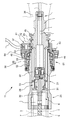
- the single figure shows an adapter device in longitudinal section.
- the adapter device 11 shown in the figure serves to set a self-drilling, chemically anchored, as a rock anchor fastener 5 by means of a here only slightly illustrated drill 8.
- chemically anchored fastener 5 this is first drilled in the ground and then pressed out the curable mass 4 located in the fastener 5.
- the adapter device 11 has a housing 36 and a rotatably mounted in the housing 36, along a longitudinal axis 22 extending rotor part 21.
- the rotor part 21 has at a first end 23 a coupling portion 24 for non-rotatably connecting the rotor part 21 with the drill 8 and at a second, the first end 23 opposite end 25 has a coupling receptacle 26 for receiving a free end 6 of the fastener 5 rotatably.
- Spülwasserkanal 27 is provided which can be coupled with a SpülwasserzuGermannase 9 of the drill 8 and opens into the coupling receptacle 26.
- a check valve 28 is provided in the flushing water channel 27, a check valve 28 is provided.
- a feed unit 29 is arranged, which has a feed nose 30 which can be coupled to an inner tube 7 which contains the mass 4 of the fastening element 5 to be pressed out.
- supply channel 31 is provided for water as Auspressmedium.
- a connection opening 37 is provided for the Auspressmedium, which is in communication with the feed channel 31 via a connecting channel section 32. Between the feed channel 31 and the connecting channel section 32, a further check valve 33 is provided.
- the housing 36 comprises a first housing part 41, which has grooved rings as sealing elements 42 between the housing 36 and the rotor part 21 for sealing the connecting channel section 32, and a second housing part 51, which between the Housing 36 and the rotor part 21 has two spaced-apart bearing elements 52 and 53 for supporting the rotor part 21 in the housing 36.
- the bearing elements 52 and 53 are biased by means of a spring means 55 arranged between them.
- the first housing part 41 has a sliding sleeve 44, which is provided between the sealing elements 42 and the rotor part 21.
- the sliding sleeve 44 is made of corrosion-resistant material, for. B. made of a stainless steel.
- two O-rings are provided as additional sealing elements 45 in recesses on the rotor part 21.
- the sliding sleeve 44 may be rotatably connected to the rotor part 21.
- the first housing part 41 is adjacent to the first end 23 of the rotor part 21 and the second housing part 51 is arranged adjacent to the second end 25 of the rotor part 21.
- the first housing part 41 and the second housing part 51 are directly connected to one another via screws as connecting means 46, for which purpose a radially projecting fastening flange 54 is provided on the second housing part 51.
- a plurality of emptying bores 43 are provided in the first housing 41 in a radially encircling manner and at a distance from one another, wherein only one of the emptying bores 43 is shown in the figure.
- the adapter device 11 is coupled on the one hand with the drill 8, wherein the SpippowasserzuGermannase 9 of the drill 8 penetrates into the flushing water channel 27 of the rotor member 21.
- a sealing element 34 is provided in the flushing water channel 27, which in the coupled state of the adapter device 11 with the drill 8 sealingly abuts the Spülwasserzu Foodnase 9.
- the adapter device 11 is coupled to the free end 6 of the fastening element 5, wherein the feed nose 30 of the feed unit 29 penetrates into the open end of the inner tube 7.
- a drill head is provided at the other, not shown end of the fastener 5.
- a line 10 for the Auspressmedium is connected.
- a rotary motion is transmitted to the self-drilling fastener 5 only with the drill 8 via the rotor part of the adapter device 11.
- rinse water is supplied from the drill 8 through the flushing water channel 27 of the rotor part 21 and the check valve 28 into the space between the inner tube 7 and the outer tube 3 the drill head.
- the rotational movement of the drill 8 stopped or stopped and passed through the line 10, the Auspressmedium, here under high pressure water, through the first housing part 41, the connecting channel section 32, the further check valve 33 and the feed passage 31 into the inner tube 7 of the fastener 5.
- the hardenable compound 4 located in the inner tube 7 is ejected from openings in the region of the drill head into the space surrounding the fastening element.
- the check valve 28 prevents any backflow of the discharged mass 4 through the annular gap between the inner tube 7 and the outer tube 3 of the fastener 5 that it can penetrate into the interior of the adapter device 11 or even the drill 8 and this dirty.
- the adapter device 11 and the drilling device 8 are uncoupled from the fastening element 5 remaining in the borehole and are available for setting a further fastening element 5.
Landscapes
- Engineering & Computer Science (AREA)
- Mining & Mineral Resources (AREA)
- Geology (AREA)
- Life Sciences & Earth Sciences (AREA)
- General Life Sciences & Earth Sciences (AREA)
- Geochemistry & Mineralogy (AREA)
- Structural Engineering (AREA)
- Mechanical Engineering (AREA)
- Physics & Mathematics (AREA)
- Environmental & Geological Engineering (AREA)
- Fluid Mechanics (AREA)
- Earth Drilling (AREA)
- Drilling And Boring (AREA)
- Joints Allowing Movement (AREA)
- Machine Tool Units (AREA)
Abstract
Description
- Die Erfindung betrifft eine Adaptervorrichtung zum Setzen eines selbstbohrenden, chemisch verankerbaren Befestigungselementes mit einem Gehäuse und mit einem im Gehäuse drehbar gelagerten, sich entlang einer Längsachse erstreckenden Rotorteil, das an einem ersten Ende einen Kupplungsabschnitt zum drehfesten Verbinden des Rotorteils mit einem Bohrgerät und an einem zweiten, dem ersten Ende gegenüberliegenden Ende eine Kupplungsaufnahme zur drehfesten Aufnahme eines freien Endes des Befestigungselementes aufweist, wobei in dem Rotorteil ein in der Kupplungsaufnahme mündender Zuführkanal für ein Auspressmedium und an dem Gehäuse eine Anschlussöffnung für das Auspressmedium vorgesehen ist, wobei die Anschlussöffnung mit dem Zuführkanal über einen Verbindungskanalabschnitt in Verbindung steht, und wobei zwischen dem Gehäuse und dem Rotorteil Lagerelemente zur Lagerung des Rotorteils im Gehäuse sowie zwischen dem Gehäuse und dem Rotorteil Dichtelemente zur Abdichtung des Verbindungskanalabschnitts vorgesehen sind.
- Selbstbohrende, chemisch verankerbare Befestigungselemente für den Baubereich und insbesondere selbstbohrende, chemisch verankerbare Gebirgsanker für den Berg- und Tunnelbereich sind seit langem bekannt. Sie dienen in erster Linie zur Stabilisierung von Baugruben oder von Wandungen in Hohlräumen, wie Tunnel, Stollen oder dergleichen. Bei der Erstellung von Baugruben und Hohlräumen werden die mechanischen Eigenschaften und insbesondere die Tragfähigkeit der Gebirgsschichten vermindert. Diese Gebirgsschichten werden mittels der chemisch verankerbaren Befestigungselemente an weiter entfernte, unbeschädigte Gebirgsschichten verankert und so an diesen gesichert.
- Aus der
DE 100 17 763 A1 ist ein selbstbohrendes, chemisch verankerbares Befestigungselement bekannt, das ein Ankerrohr mit einem Bohrkopf an einem Ende und einem Angriffsmittel für ein Bohrgerät an dem anderen, freien Ende aufweist. Im Rohrelement sind eine Aufnahme für eine auszupressende Masse, die auszupressende Masse selbst und ein Auspresskolben vorgesehen. In einem ersten Schritt wird mit dem Bohrgerät das Befestigungselement in den Untergrund gebohrt. In einem weiteren Schritt wird beispielsweise nach dem Entfernen des Bohrgeräts eine Auspressvorrichtung am Angriffsmittel angeordnet und mittels eines Auspressmechanismus die auszupressende Masse in Richtung des Bohrkopfs ausgepresst. Durch Austrittsöffnungen am Bohrkopf dringt die ausgepresste Masse in den Bohrlochgrund und in den Ringspalt zwischen der Bohrlochwandung und dem Ankerrohr ein. Nach dem Aushärten der ausgepressten Masse ist das Befestigungselement im Untergrund verankert. - Zum Setzen eines derartigen Befestigungselementes, d. h. zum Bohren des Befestigungselementes in den Untergrund und zum anschliessenden Auspressen der im Befestigungselement befindlichen aushärtbaren Masse, ist aus der
DE 103 34 374 A1 eine Adaptervorrichtung bekannt, die ein Gehäuse und ein im Gehäuse drehbar gelagertes, sich entlang einer Längsachse erstreckendes Rotorteil aufweist. Das Rotorteil weist an einem ersten Ende einen Kupplungsabschnitt zum drehfesten Verbinden des Rotorteils mit einem Bohrgerät und an einem zweiten, dem ersten Ende gegenüberliegenden Ende eine Kupplungsaufnahme zur drehfesten Aufnahme eines freien Endes des Befestigungselementes auf. In dem Rotorteil ist ein in der Kupplungsaufnahme mündender Zuführkanal für ein Auspressmedium und an dem Gehäuse eine Anschlussöffnung für das Auspressmedium vorgesehen, wobei die Anschlussöffnung mit dem Zuführkanal über einen Verbindungskanalabschnitt in Verbindung steht. Zwischen dem Gehäuse und dem Rotorteil sind beabstandet zum Aussenrand des Gehäuses Lagerelemente zur Lagerung des Rotorteils im Gehäuse sowie zwischen dem Gehäuse und dem Rotorteil innenseitig, jeweils beabstandet zu den Lagerelementen Dichtelemente zur Abdichtung des Verbindungskanalabschnitts vorgesehen. Als Auspressmedium zum Ausbringen der aushärtbaren Masse aus dem Befestigungselement kommt unter Hochdruck gesetztes Wasser zum Einsatz. Zusätzlich ist ein in axialer Richtung das Rotorteil durchdringender zweiter Spülwasserkanal vorgesehen, durch den während dem Bohrvorgang Spülwasser dem Bohrkopf des Befestigungselementes zugeführt und/oder Bohrklein vom Bohrkopf des Befestigungselementes abgeführt werden kann. - Diese Adaptervorrichtung ermöglicht ein Bohren und ein anschliessendes Auspressen, ohne dass das Bohrgerät abgekoppelt und eine separate Auspressvorrichtung zum Auspressen der in dem Befestigungselement befindlichen aushärtbaren Masse angeordnet werden muss. Damit reduziert sich der Setzaufwand des Befestigungselementes massgeblich.
- Nachteilig an der bekannten Lösung ist, dass bei einem Verschleiss der Dichtelemente auftretende Undichtigkeiten zu Lagerschäden führen und die Herstellung sowie der Unterhalt der Adaptervorrichtung aufwändig ist.
- Aufgabe der Erfindung ist es, eine gattungsgemässe Adaptervorrichtung zu schaffen, die einfach im Aufbau ist und eine hohe Servicefreundlichkeit aufweist.
- Die Aufgabe ist durch die Merkmale des unabhängigen Anspruchs gelöst. Vorteilhafte Weiterbildungen sind in den Unteransprüchen dargelegt.
- Gemäss der Erfindung weist das Gehäuse ein erstes Gehäuseteil, das die Dichtelemente aufweist, und ein zweites Gehäuseteil auf, das die Lagerelemente aufweist.
- Das Gehäuse besteht somit aus zwei separaten Modulen, wobei das erste Gehäuseteil die Funktion der Übergabe des Auspressmediums an das Befestigungselement und das zweite Gehäuseteil die Funktion der Lagerung des Rotorteils übernimmt. Durch die Trennung der beiden Funktionen sind die einzelnen Module kompakt und mit kleiner Baugrösse herstellbar. Weiter sind diese Gehäuseteile voneinander unabhängig und können jederzeit einzeln ausgewechselt werden.
- Die Dichtelemente sind vorteilhaft als Nutringe ausgebildet. Da das erste Gehäuseteil an seinem in Bezug auf das Rotorteil axialen Endbereichen keine Lagerelemente aufweist und die Dichtelemente somit näher an den axialen Enden angeordnet werden können, sind diese im Falle eines Verschleisses leicht zugänglich und somit einfacher auswechselbar. Die beispielsweise als Rillenkugellager ausgebildeten Lagerelemente können einen geringen Abstand aufweisen, der zur Lagerung des Rotorteils im zweiten Gehäuseteil ausreicht. Dies ermöglicht eine kompakte Ausbildung des zweiten Gehäuseteils und somit eine kurze Baulänge desselben. Vorteilhaft sind bei dem zweiten Gehäuseteil am in Bezug auf das Rotorteil axialen Endbereich von aussen leicht zugängliche Dichtelemente vorgesehen, wobei diese optionalen Dichtelemente bei einem Verschleiss derselben ebenfalls einfach austauschbar sind.
- Vorzugsweise sind das erste Gehäuseteil und das zweite Gehäuseteil über Verbindungsmittel, z. B. Schrauben, direkt miteinander verbunden, womit sich das zweite Gehäuseteil in axialer Richtung direkt an das erste Gehäuseteil anschliesst. Damit ist das gesamte Gehäuse kompakt ausgebildet und die gesamte Adaptervorrichtung weist somit eine kurze Baulänge auf, was insbesondere im Bergbau, wo das Setzen der Befestigungselemente in Bereichen mit zumeist engen Platzverhältnissen erfolgt, einen massgeblichen Vorteil darstellt.
- Bevorzugt ist ein Befestigungsflansch an zumindest einem der Gehäuseteile vorgesehen, der eine leicht von aussen zugängliche Anordnung der Verbindungsmittel ermöglicht. Vorteilhaft ist der Befestigungsflansch an dem zweiten Gehäuseteil mit den Lagerelementen vorgesehen.
- Vorzugsweise ist zumindest eine Entleerungsbohrung an dem ersten Gehäuseteil vorgesehen, welche bei einer allfälligen Leckage zwischen dem Rotorteil und dem ersten Gehäuseteil ein Ableiten des gegebenenfalls anfallenden Auspressmediums aus dem zusammengesetzten Gehäuse ermöglicht und somit eine Schädigung der Lagerelemente im zweiten Gehäuseteil durch das ausgetretende Auspressmedium weitgehend verhindert. Vorteilhaft sind mehrere Entleerungsbohrungen vorgesehen, welche weiter vorteilhaft radial umlaufend und beabstandet zueinander vorgesehen sind Vorteilhaft weist das zweite Gehäuseteil ebenfalls zumindest eine Entleerungsbohrung auf, durch welche anfallendes Auspressmedium zum Schutz der Lagerelemente abgeleitet wird.
- Bevorzugt ist das erste Gehäuseteil benachbart zum ersten Ende des Rotorteils und das zweite Gehäuseteil benachbart zum zweiten Ende des Rotorteils angeordnet. Mit dieser Anordnung der Gehäuseteile zueinander steht auch bei einer kurzen Ausgestaltung der Adaptervorrichtung eine ausreichende Baulänge für die Umlenkung des Auspressmediums aus dem Gehäuse in das Rotorteil zur Verfügung.
- Vorzugsweise sind zumindest zwei Lagerelemente im zweiten Gehäuseteil vorgesehen, wobei zumindest eines der Lagerelemente mittels eines Federmittels vorgespannt ist. Die Vorspannung des zumindest einen Lagerelementes gewährleistet eine spielfreie Lagerung des Rotorteils, wodurch der Abstand zwischen den Lagerelementen und somit die gesamte Baulänge des zweiten Gehäuseteils reduzierbar ist.
- Bevorzugt weist das erste Gehäuseteil eine Gleithülse auf, die zwischen den Dichtelementen und dem Rotorteil vorgesehen ist zur Verhinderung einer direkten Anlage der Dichtelemente an dem Rotorteil. Damit sind eine einfache Montage sowie eine lange Gebrauchstauglichkeit des ersten Gehäuseteils gewährleistet. Die Gleithülse schützt die Dichtelemente vor Verschleiss sowie Korrosion und ermöglicht eine einfache Montage des die Dichtfunktion übernehmenden, ersten Gehäuseteils an dem Rotorteil. Vorteilhaft sind zur Abdichtung der Gleithülse zum Rotorteil zusätzliche Dichtelemente, z. B. O-Ringe, zwischen der Gleithülse und dem Rotorteil vorgesehen.
- Vorzugsweise ist die Gleithülse aus korrosionsbeständigem Material gefertigt, was insbesondere bei Wasser als Auspressmedium vorteilhaft ist. Diese Gleithülse, welche vorteilhaft mit dem Rotorteil drehfest verbunden und mit den Dichtelementen im ersten Gehäuseteil in direkter Anlage ist, weist mit dieser Materialwahl einen geringen Verschleiss auf und gewährleistet somit zusätzlich eine lange Gebrauchstauglichkeit des ersten Gehäuseteils.
- Die Erfindung wird nachstehend anhand eines Ausführungsbeispiels näher erläutert. Die einzige Figur zeigt eine Adaptervorrichtung im Längsschnitt.
- Die in der Figur dargestellte Adaptervorrichtung 11 dient dem Setzen eines selbstbohrenden, chemisch verankerbaren, hier ansatzweise dargestellten, als Gebirgsanker ausgebildeten Befestigungselementes 5 mittels eines hier nur ansatzweise dargestellten Bohrgerätes 8. Zum Setzen des selbstbohrenden, chemisch verankerbaren Befestigungselementes 5 wird dieses zuerst in den Untergrund gebohrt und anschliessend die im Befestigungselement 5 befindliche aushärtbare Masse 4 ausgepresst.
- Die Adaptervorrichtung 11 weist ein Gehäuse 36 und ein im Gehäuse 36 drehbar gelagertes, sich entlang einer Längsachse 22 erstreckendes Rotorteil 21 auf. Das Rotorteil 21 weist an einem ersten Ende 23 einen Kupplungsabschnitt 24 zum drehfesten Verbinden des Rotorteils 21 mit dem Bohrgerät 8 und an einem zweiten, dem ersten Ende 23 gegenüberliegenden Ende 25 eine Kupplungsaufnahme 26 zur drehfesten Aufnahme eines freien Endes 6 des Befestigungselementes 5 auf. In dem Rotorteil 21 ist einerseits ein sich über die gesamte axiale Länge des Rotorteils erstreckender Spülwasserkanal 27 vorgesehen, der mit einer Spülwasserzuführnase 9 des Bohrgerätes 8 kuppelbar ist und in der Kupplungsaufnahme 26 mündet. Im Spülwasserkanal 27 ist ein Rückschlagventil 28 vorgesehen. In dem der Kupplungsaufnahme 26 zugewandten Bereich des Rotorteils 21 ist eine Zuführeinheit 29 angeordnet, die eine mit einem Innenrohr 7, das die auszupressende Masse 4 des Befestigungselementes 5 beinhaltet, kuppelbare Zuführnase 30 aufweist. In der Zuführnase 30 ist ein in der Kupplungsaufnahme 26 mündender Zuführkanal 31 für Wasser als Auspressmedium vorgesehen.
- An dem Gehäuse 36 ist eine Anschlussöffnung 37 für das Auspressmedium vorgesehen, die mit dem Zuführkanal 31 über einen Verbindungskanalabschnitt 32 in Verbindung steht. Zwischen dem Zuführkanal 31 und dem Verbindungskanalabschnitt 32 ist ein weiteres Rückschlagventil 33 vorgesehen.
- Das Gehäuse 36 umfasst ein erstes Gehäuseteil 41, das Nutringe als Dichtelemente 42 zwischen dem Gehäuse 36 und dem Rotorteil 21 zur Abdichtung des Verbindungskanalabschnitts 32 aufweist, und ein zweites Gehäuseteil 51, das zwischen dem Gehäuse 36 und dem Rotorteil 21 zwei zueinander beabstandete Lagerelemente 52 und 53 zur Lagerung des Rotorteils 21 im Gehäuse 36 aufweist. Die Lagerelemente 52 und 53 sind mittels eines zwischen diesen angeordneten Federmittels 55 vorgespannt.
- Das erste Gehäuseteil 41 weist eine Gleithülse 44 auf, die zwischen den Dichtelementen 42 und dem Rotorteil 21 vorgesehen ist. Die Gleithülse 44 ist aus korrosionsbeständigem Material, z. B. aus einem nichtrostenden Stahl gefertigt. Zur Abdichtung der Gleithülse 44 zum Rotorteil 21 sind zwei O-Ringe als zusätzliche Dichtelemente 45 in Ausnehmungen am Rotorteil 21 vorgesehen. Die Gleithülse 44 kann drehfest mit dem Rotorteil 21 verbunden sein.
- Das erste Gehäuseteil 41 ist benachbart zum ersten Ende 23 des Rotorteils 21 und das zweite Gehäuseteil 51 ist benachbart zum zweiten Ende 25 des Rotorteils 21 angeordnet. Das erste Gehäuseteil 41 und das zweite Gehäuseteil 51 sind über Schrauben als Verbindungsmittel 46 direkt miteinander verbunden, wozu an dem zweiten Gehäuseteil 51 ein radial abragender Befestigungsflansch 54 vorgesehen ist. Zur Entleerung von allfällig in das Gehäuse 36 austretendem Auspressmedium sind im ersten Gehäuse 41 radial umlaufend sowie beabstandet zueinander mehrere Entleerungsbohrungen 43 vorgesehen, wobei in der Figur nur eine der Entleerungsbohrungen 43 dargestellt ist.
- Nachfolgend wird der Setzvorgang eines Befestigungselementes 5 mit der Adaptervorrichtung 11 dargelegt. Die Adaptervorrichtung 11 wird einerseits mit dem Bohrgerät 8 gekuppelt, wobei die Spülwasserzuführnase 9 des Bohrgerätes 8 in den Spülwasserkanal 27 des Rotorteils 21 eindringt. Im Bereich des ersten Endes des Rotorteils 21 ist im Spülwasserkanal 27 ein Abdichtelement 34 vorgesehen, das im gekuppelten Zustand der Adaptervorrichtung 11 mit dem Bohrgerät 8 sich dichtend an die Spülwasserzuführnase 9 anlegt. Die Adaptervorrichtung 11 wird andererseits mit dem freien Ende 6 des Befestigungselementes 5 gekuppelt, wobei die Zuführnase 30 der Zuführeinheit 29 in das offene Ende des Innenrohres 7 eindringt. An dem anderen, hier nicht dargestellten Ende des Befestigungselementes 5 ist ein Bohrkopf vorgesehen. An der Anschlussöffnung 37 des Gehäuses 36 wird eine Leitung 10 für das Auspressmedium angeschlossen.
- In einem ersten Schritt wird mit dem Bohrgerät 8 einzig über das Rotorteil der Adaptervorrichtung 11 eine Drehbewegung auf das selbstbohrende Befestigungselement 5 übertragen. Während dem Bohrvorgang wird Spülwasser aus dem Bohrgerät 8 durch den Spülwasserkanal 27 des Rotorteils 21 und das Rückschlagventil 28 hindurch in den Zwischenraum zwischen dem Innenrohr 7 und dem Aussenrohr 3 dem Bohrkopf zugeleitet. Nach Erreichen der gewünschten Bohrtiefe wird die Drehbewegung des Bohrgerätes 8 abgestellt beziehungsweise gestoppt und über die Leitung 10 das Auspressmedium, hier unter Hochdruck stehendes Wasser, durch das erste Gehäuseteil 41, den Verbindungskanalabschnitt 32, das weitere Rückschlagventil 33 und den Zuführkanal 31 hindurch in das Innenrohr 7 des Befestigungselementes 5 geleitet. Dadurch wird die sich im Innenrohr 7 befindliche aushärtbare Masse 4 aus Öffnungen im Bereich des Bohrkopfs in den das Befestigungselement umgebenden Raum ausgebracht. Insbesondere das Rückschlagventil 28 verhindert bei einem allfälligen Zurückfliessen der ausgebrachten Masse 4 durch den Ringspalt zwischen dem Innenrohr 7 und dem Aussenrohr 3 des Befestigungselementes 5, dass diese in das Innere der Adaptervorrichtung 11 oder gar des Bohrgerätes 8 dringen kann und diese verschmutzt.
- Nach dem Aushärten der aushärtbare Masse 4 im Bohrloch wird die Adaptervorrichtung 11 und das Bohrgerät 8 von dem im Bohrloch verbleibenden Befestigungselement 5 abgekoppelt und steht zum Setzen eines weiteren Befestigungselementes 5 zur Verfügung.
Claims (8)
- Adaptervorrichtung zum Setzen eines selbstbohrenden, chemisch verankerbaren Befestigungselementes (5) mit einem Gehäuse (36) und
mit einem im Gehäuse (36) drehbar gelagerten, sich entlang einer Längsachse (22) erstreckenden Rotorteil (21), das an einem ersten Ende (23) einen Kupplungsabschnitt (24) zum drehfesten Verbinden des Rotorteils (21) mit einem Bohrgerät (8) und an einem zweiten, dem ersten Ende (23) gegenüberliegenden Ende (25) eine Kupplungsaufnahme (26) zur drehfesten Aufnahme eines freien Endes (6) des Befestigungselementes (5) aufweist, wobei
in dem Rotorteil (21) ein in der Kupplungsaufnahme (26) mündender Zuführkanal (31) für ein Auspressmedium und
an dem Gehäuse (36) eine Anschlussöffnung (37) für das Auspressmedium vorgesehen ist, wobei die Anschlussöffnung (37) mit dem Zuführkanal (31) über einen Verbindungskanalabschnitt (32) in Verbindung steht, und wobei
zwischen dem Gehäuse (36) und dem Rotorteil (21) Lagerelemente (52, 53) zur Lagerung des Rotorteils (21) im Gehäuse (36) sowie zwischen dem Gehäuse (36) und dem Rotorteil (21) Dichtelemente (42) zur Abdichtung des Verbindungskanalabschnitts (32) vorgesehen sind, dadurch gekennzeichnet, dass
das Gehäuse (36) ein erstes Gehäuseteil (41), das die Dichtelemente (42) aufweist, und ein zweites Gehäuseteil (51) aufweist, das die Lagerelemente (52, 53) aufweist. - Adaptervorrichtung nach Anspruch 1, dadurch gekennzeichnet, dass das erste Gehäuseteil (41) und das zweite Gehäuseteil (51) über Verbindungsmittel (46) direkt miteinander verbunden sind.
- Adaptervorrichtung nach Anspruch 2, dadurch gekennzeichnet, dass ein Befestigungsflansch (54) an zumindest einem der Gehäuseteile (41) zum Verbinden der Gehäuseteile (41, 51) vorgesehen ist.
- Adaptervorrichtung nach einem der Ansprüche 1 bis 3, dadurch gekennzeichnet, dass zumindest eine Entleerungsbohrung (43) an dem ersten Gehäuseteil (41) vorgesehen ist.
- Adaptervorrichtung nach einem der Ansprüche 1 bis 4, dadurch gekennzeichnet, dass das erste Gehäuseteil (41) benachbart zum ersten Ende (23) des Rotorteils (21) und das zweite Gehäuseteil (51) benachbart zum zweiten Ende (25) des Rotorteils (21) angeordnet ist.
- Adaptervorrichtung nach einem der Ansprüche 1 bis 5, dadurch gekennzeichnet, dass zumindest zwei Lagerelemente (52, 53) im zweiten Gehäuseteil (51) vorgesehen sind, wobei zumindest eines der Lagerelemente (52, 53) mittels eines Federmittels (55) vorgespannt ist.
- Adaptervorrichtung nach einem der Ansprüche 1 bis 6, dadurch gekennzeichnet, dass das erste Gehäuseteil (41) eine Gleithülse (44) aufweist, die zwischen den Dichtelementen (42) und dem Rotorteil (21) vorgesehen ist.
- Adaptervorrichtung nach Anspruch 7, dadurch gekennzeichnet, dass die Gleithülse (44) aus korrosionsbeständigem Material gefertigt ist.
Applications Claiming Priority (1)
| Application Number | Priority Date | Filing Date | Title |
|---|---|---|---|
| DE102008002303A DE102008002303A1 (de) | 2008-06-09 | 2008-06-09 | Adaptervorrichtung zum Setzen eines selbstbohrenden, chemisch verankerbaren Befestigungselementes |
Publications (2)
| Publication Number | Publication Date |
|---|---|
| EP2133510A2 true EP2133510A2 (de) | 2009-12-16 |
| EP2133510A3 EP2133510A3 (de) | 2016-09-14 |
Family
ID=41009988
Family Applications (1)
| Application Number | Title | Priority Date | Filing Date |
|---|---|---|---|
| EP09159594.2A Withdrawn EP2133510A3 (de) | 2008-06-09 | 2009-05-07 | Adaptervorrichtung zum Setzen eines selbstbohrenden, chemisch verankerbaren Befestigungselementes |
Country Status (6)
| Country | Link |
|---|---|
| US (1) | US8029211B2 (de) |
| EP (1) | EP2133510A3 (de) |
| CN (1) | CN101603430B (de) |
| AU (1) | AU2009201844B2 (de) |
| DE (1) | DE102008002303A1 (de) |
| ZA (1) | ZA200903993B (de) |
Cited By (3)
| Publication number | Priority date | Publication date | Assignee | Title |
|---|---|---|---|---|
| WO2013127407A1 (de) * | 2012-03-02 | 2013-09-06 | Dh Mining System Gmbh | Einrichtung zum bohren von löchern sowie zum setzen von gebirgsankern |
| WO2013127408A1 (de) * | 2012-03-02 | 2013-09-06 | Dh Mining System Gmbh | Einrichtung zum bohren und ankersetzen |
| WO2013127409A1 (de) * | 2012-03-02 | 2013-09-06 | Dh Mining System Gmbh | Einrichtung zum bohren und setzen von gebirgsankern |
Families Citing this family (7)
| Publication number | Priority date | Publication date | Assignee | Title |
|---|---|---|---|---|
| DE102006000042A1 (de) * | 2006-01-31 | 2007-08-02 | Hilti Ag | Adapterteil eines selbstbohrenden Gebirgsankers |
| DE102009001464A1 (de) * | 2009-03-11 | 2010-09-16 | Hilti Aktiengesellschaft | Adapter eines selbstbohrenden, chemisch verankerbaren Befestigungselementes |
| CA2777995C (en) | 2011-06-08 | 2018-10-30 | Giddicca (Pty) Ltd | An adhesive containing tubular rock anchor |
| AT511616B1 (de) * | 2011-09-08 | 2013-01-15 | Tmt Bbg Res And Dev Gmbh | Einrichtung zur zuführung von spülmedium in einem bohrhammer |
| CN104018862A (zh) * | 2014-06-26 | 2014-09-03 | 河北联合大学 | 高预紧锚杆张拉装置 |
| BR112018007523A2 (pt) | 2015-10-14 | 2018-10-23 | Sandvik Intellectual Property Ab | aparelho extensível, cabeça de broca, e método |
| CN113202523B (zh) * | 2021-04-30 | 2022-12-20 | 中煤科工开采研究院有限公司 | 多功能一体化锚杆施工装置 |
Citations (2)
| Publication number | Priority date | Publication date | Assignee | Title |
|---|---|---|---|---|
| DE10017763A1 (de) | 2000-04-10 | 2001-10-11 | Hilti Ag | Gebirgsanker |
| DE10334374A1 (de) | 2003-07-28 | 2005-03-17 | Hilti Ag | Auspressvorrichtung |
Family Cites Families (10)
| Publication number | Priority date | Publication date | Assignee | Title |
|---|---|---|---|---|
| US4449596A (en) * | 1982-08-03 | 1984-05-22 | Varco International, Inc. | Drilling of wells with top drive unit |
| DE4432472C2 (de) * | 1994-09-13 | 1997-09-18 | Reburg Patentverwertungs Gmbh | Adapterteil zum Verbinden eines Bohrantriebs mit einem selbstbohrenden Anker |
| US6230824B1 (en) * | 1998-03-27 | 2001-05-15 | Hydril Company | Rotating subsea diverter |
| CA2450432C (en) * | 2001-06-12 | 2007-12-04 | Utex Industries, Inc. | Packing assembly for rotary drilling swivels |
| US20050012278A1 (en) * | 2002-11-07 | 2005-01-20 | Delange Richard W. | Metal sleeve seal for threaded connections |
| AU2002953376A0 (en) * | 2002-12-17 | 2003-01-09 | Lms Geotechnical Pty Ltd | An apparatus and method to anchor a rock bolt |
| CN2622391Y (zh) * | 2003-03-20 | 2004-06-30 | 付庆福 | 自钻式砂粒灌浆锚具 |
| CN2740822Y (zh) * | 2004-11-02 | 2005-11-16 | 北京交通大学 | 一种帮锚索钻机的供气机构 |
| DE102005000158A1 (de) * | 2005-11-16 | 2007-05-24 | Hilti Ag | Bohr- und Ankersetzgerät mit integrierter Auspressvorrichtung |
| DE102007008966A1 (de) * | 2006-02-24 | 2007-09-06 | Friedr. Ischebeck Gmbh | Injektionskopf |
-
2008
- 2008-06-09 DE DE102008002303A patent/DE102008002303A1/de not_active Withdrawn
-
2009
- 2009-05-07 EP EP09159594.2A patent/EP2133510A3/de not_active Withdrawn
- 2009-05-08 AU AU2009201844A patent/AU2009201844B2/en active Active
- 2009-06-03 CN CN200910145327.7A patent/CN101603430B/zh not_active Expired - Fee Related
- 2009-06-08 US US12/455,888 patent/US8029211B2/en not_active Expired - Fee Related
- 2009-06-08 ZA ZA200903993A patent/ZA200903993B/xx unknown
Patent Citations (2)
| Publication number | Priority date | Publication date | Assignee | Title |
|---|---|---|---|---|
| DE10017763A1 (de) | 2000-04-10 | 2001-10-11 | Hilti Ag | Gebirgsanker |
| DE10334374A1 (de) | 2003-07-28 | 2005-03-17 | Hilti Ag | Auspressvorrichtung |
Cited By (3)
| Publication number | Priority date | Publication date | Assignee | Title |
|---|---|---|---|---|
| WO2013127407A1 (de) * | 2012-03-02 | 2013-09-06 | Dh Mining System Gmbh | Einrichtung zum bohren von löchern sowie zum setzen von gebirgsankern |
| WO2013127408A1 (de) * | 2012-03-02 | 2013-09-06 | Dh Mining System Gmbh | Einrichtung zum bohren und ankersetzen |
| WO2013127409A1 (de) * | 2012-03-02 | 2013-09-06 | Dh Mining System Gmbh | Einrichtung zum bohren und setzen von gebirgsankern |
Also Published As
| Publication number | Publication date |
|---|---|
| US8029211B2 (en) | 2011-10-04 |
| AU2009201844A1 (en) | 2009-12-24 |
| EP2133510A3 (de) | 2016-09-14 |
| AU2009201844B2 (en) | 2011-03-31 |
| CN101603430A (zh) | 2009-12-16 |
| CN101603430B (zh) | 2013-10-30 |
| ZA200903993B (en) | 2010-03-31 |
| US20090304455A1 (en) | 2009-12-10 |
| DE102008002303A1 (de) | 2009-12-10 |
Similar Documents
| Publication | Publication Date | Title |
|---|---|---|
| DE102008002303A1 (de) | Adaptervorrichtung zum Setzen eines selbstbohrenden, chemisch verankerbaren Befestigungselementes | |
| DE102008003968B3 (de) | Bohranlage | |
| EP0397874A1 (de) | Vorrichtung zum schliessen einer schwierigkeitszone in einem bohrloch | |
| DE10336043B4 (de) | Verbundanker | |
| DE102011005855A1 (de) | Gesteinsanker | |
| DE602004012884T2 (de) | Verfahren und vorrichtung zum installieren eines selbstbohrenden expandierenden gebirgsankers und selbstbohrender gebirgsanker | |
| DE102008006236A1 (de) | Injektionskopf für Injektionsbohranker | |
| DE102005000158A1 (de) | Bohr- und Ankersetzgerät mit integrierter Auspressvorrichtung | |
| EP0851091A2 (de) | Imlochhammer | |
| CH697257B1 (de) | Bohrvorrichtung. | |
| DE102010023627B4 (de) | Selbstbohranker | |
| EP2065559A2 (de) | Selbstbohrender Verbundanker | |
| WO2009092659A2 (de) | Injektionskopf | |
| DE112010002712B4 (de) | Führungsvorrichtung für eine bohrvorrichtung | |
| DE102005000142A1 (de) | Auspressvorrichtung | |
| DE102006011652B4 (de) | Zweischritt-Hohlstabverbundanker für Kleberpatronen und Klebergranulat | |
| EP2850284A1 (de) | Einrichtung zum bohren und ankersetzen | |
| DE10148683C1 (de) | Injektionsbohrsanker | |
| DE4037261A1 (de) | Zielbohrstange mit einer rohrwellenlagerung | |
| EP1818499B1 (de) | Einrichtung zum gleichzeitigen Bohren und Auskleiden von Bohrlöchern | |
| EP2094933B1 (de) | Vorrrichtung zum schlag- bzw. drehschlagbohren in gesteinsmaterial | |
| EP2029851B1 (de) | Spülwelle für das bohrgestänge einer drehschlagbohranlage, prallpaket für eine spülwelle und drehschlagbohranlage | |
| DE10334374B4 (de) | Auspressvorrichtung | |
| DE202008004473U1 (de) | Bohrantriebseinheit für ein Doppelbohrgestänge | |
| WO2013174681A1 (de) | Gesteinsanker |
Legal Events
| Date | Code | Title | Description |
|---|---|---|---|
| PUAI | Public reference made under article 153(3) epc to a published international application that has entered the european phase |
Free format text: ORIGINAL CODE: 0009012 |
|
| AK | Designated contracting states |
Kind code of ref document: A2 Designated state(s): AT BE BG CH CY CZ DE DK EE ES FI FR GB GR HR HU IE IS IT LI LT LU LV MC MK MT NL NO PL PT RO SE SI SK TR |
|
| PUAL | Search report despatched |
Free format text: ORIGINAL CODE: 0009013 |
|
| RAP1 | Party data changed (applicant data changed or rights of an application transferred) |
Owner name: DYWIDAG-SYSTEMS INTERNATIONAL PTY LIMITED |
|
| AK | Designated contracting states |
Kind code of ref document: A3 Designated state(s): AT BE BG CH CY CZ DE DK EE ES FI FR GB GR HR HU IE IS IT LI LT LU LV MC MK MT NL NO PL PT RO SE SI SK TR |
|
| AX | Request for extension of the european patent |
Extension state: AL BA RS |
|
| RIC1 | Information provided on ipc code assigned before grant |
Ipc: E21D 20/02 20060101AFI20160810BHEP |
|
| STAA | Information on the status of an ep patent application or granted ep patent |
Free format text: STATUS: THE APPLICATION IS DEEMED TO BE WITHDRAWN |
|
| 18D | Application deemed to be withdrawn |
Effective date: 20170315 |