EP2133238B1 - Appareil d'imagerie et procédé de correction d'images - Google Patents
Appareil d'imagerie et procédé de correction d'images Download PDFInfo
- Publication number
- EP2133238B1 EP2133238B1 EP09251295.3A EP09251295A EP2133238B1 EP 2133238 B1 EP2133238 B1 EP 2133238B1 EP 09251295 A EP09251295 A EP 09251295A EP 2133238 B1 EP2133238 B1 EP 2133238B1
- Authority
- EP
- European Patent Office
- Prior art keywords
- imaging
- pixel data
- optical filter
- coordinate transformation
- imaging apparatus
- Prior art date
- Legal status (The legal status is an assumption and is not a legal conclusion. Google has not performed a legal analysis and makes no representation as to the accuracy of the status listed.)
- Not-in-force
Links
- 238000003384 imaging method Methods 0.000 title claims description 113
- 238000000034 method Methods 0.000 title claims description 28
- 238000003702 image correction Methods 0.000 title claims 3
- 230000003287 optical effect Effects 0.000 claims description 168
- 230000009466 transformation Effects 0.000 claims description 106
- 238000012937 correction Methods 0.000 claims description 87
- 230000004075 alteration Effects 0.000 claims description 86
- 230000015654 memory Effects 0.000 claims description 85
- 238000012545 processing Methods 0.000 claims description 23
- 230000007423 decrease Effects 0.000 claims description 7
- 230000035945 sensitivity Effects 0.000 claims description 4
- 238000010586 diagram Methods 0.000 description 38
- 230000002093 peripheral effect Effects 0.000 description 20
- 230000008569 process Effects 0.000 description 20
- 230000000694 effects Effects 0.000 description 18
- 239000002131 composite material Substances 0.000 description 12
- 238000002834 transmittance Methods 0.000 description 10
- 230000015556 catabolic process Effects 0.000 description 4
- 238000006243 chemical reaction Methods 0.000 description 4
- 238000006731 degradation reaction Methods 0.000 description 4
- 230000008859 change Effects 0.000 description 3
- 238000007796 conventional method Methods 0.000 description 3
- 238000013461 design Methods 0.000 description 3
- 238000001914 filtration Methods 0.000 description 3
- 230000006870 function Effects 0.000 description 3
- 230000004048 modification Effects 0.000 description 3
- 238000012986 modification Methods 0.000 description 3
- 230000004044 response Effects 0.000 description 3
- 239000000758 substrate Substances 0.000 description 3
- 230000005540 biological transmission Effects 0.000 description 2
- 239000003086 colorant Substances 0.000 description 2
- 230000003247 decreasing effect Effects 0.000 description 2
- 238000006073 displacement reaction Methods 0.000 description 2
- 238000012546 transfer Methods 0.000 description 2
- 230000002411 adverse Effects 0.000 description 1
- 230000000295 complement effect Effects 0.000 description 1
- 230000000593 degrading effect Effects 0.000 description 1
- 230000001419 dependent effect Effects 0.000 description 1
- 230000005855 radiation Effects 0.000 description 1
- 239000004065 semiconductor Substances 0.000 description 1
- 230000003068 static effect Effects 0.000 description 1
- 230000004304 visual acuity Effects 0.000 description 1
Images


Classifications
-
- G—PHYSICS
- G02—OPTICS
- G02B—OPTICAL ELEMENTS, SYSTEMS OR APPARATUS
- G02B13/00—Optical objectives specially designed for the purposes specified below
- G02B13/06—Panoramic objectives; So-called "sky lenses" including panoramic objectives having reflecting surfaces
-
- G—PHYSICS
- G02—OPTICS
- G02B—OPTICAL ELEMENTS, SYSTEMS OR APPARATUS
- G02B27/00—Optical systems or apparatus not provided for by any of the groups G02B1/00 - G02B26/00, G02B30/00
- G02B27/0025—Optical systems or apparatus not provided for by any of the groups G02B1/00 - G02B26/00, G02B30/00 for optical correction, e.g. distorsion, aberration
-
- G—PHYSICS
- G02—OPTICS
- G02B—OPTICAL ELEMENTS, SYSTEMS OR APPARATUS
- G02B5/00—Optical elements other than lenses
- G02B5/20—Filters
- G02B5/205—Neutral density filters
-
- G—PHYSICS
- G03—PHOTOGRAPHY; CINEMATOGRAPHY; ANALOGOUS TECHNIQUES USING WAVES OTHER THAN OPTICAL WAVES; ELECTROGRAPHY; HOLOGRAPHY
- G03B—APPARATUS OR ARRANGEMENTS FOR TAKING PHOTOGRAPHS OR FOR PROJECTING OR VIEWING THEM; APPARATUS OR ARRANGEMENTS EMPLOYING ANALOGOUS TECHNIQUES USING WAVES OTHER THAN OPTICAL WAVES; ACCESSORIES THEREFOR
- G03B7/00—Control of exposure by setting shutters, diaphragms or filters, separately or conjointly
- G03B7/18—Control of exposure by setting shutters, diaphragms or filters, separately or conjointly in accordance with light-reducing "factor" of filter or other obturator used with or on the lens of the camera
-
- G—PHYSICS
- G06—COMPUTING; CALCULATING OR COUNTING
- G06T—IMAGE DATA PROCESSING OR GENERATION, IN GENERAL
- G06T5/00—Image enhancement or restoration
- G06T5/20—Image enhancement or restoration using local operators
-
- G—PHYSICS
- G06—COMPUTING; CALCULATING OR COUNTING
- G06T—IMAGE DATA PROCESSING OR GENERATION, IN GENERAL
- G06T5/00—Image enhancement or restoration
- G06T5/80—Geometric correction
-
- H—ELECTRICITY
- H04—ELECTRIC COMMUNICATION TECHNIQUE
- H04N—PICTORIAL COMMUNICATION, e.g. TELEVISION
- H04N23/00—Cameras or camera modules comprising electronic image sensors; Control thereof
- H04N23/10—Cameras or camera modules comprising electronic image sensors; Control thereof for generating image signals from different wavelengths
-
- H—ELECTRICITY
- H04—ELECTRIC COMMUNICATION TECHNIQUE
- H04N—PICTORIAL COMMUNICATION, e.g. TELEVISION
- H04N23/00—Cameras or camera modules comprising electronic image sensors; Control thereof
- H04N23/80—Camera processing pipelines; Components thereof
- H04N23/84—Camera processing pipelines; Components thereof for processing colour signals
- H04N23/843—Demosaicing, e.g. interpolating colour pixel values
-
- H—ELECTRICITY
- H04—ELECTRIC COMMUNICATION TECHNIQUE
- H04N—PICTORIAL COMMUNICATION, e.g. TELEVISION
- H04N25/00—Circuitry of solid-state image sensors [SSIS]; Control thereof
- H04N25/10—Circuitry of solid-state image sensors [SSIS]; Control thereof for transforming different wavelengths into image signals
- H04N25/11—Arrangement of colour filter arrays [CFA]; Filter mosaics
- H04N25/13—Arrangement of colour filter arrays [CFA]; Filter mosaics characterised by the spectral characteristics of the filter elements
- H04N25/134—Arrangement of colour filter arrays [CFA]; Filter mosaics characterised by the spectral characteristics of the filter elements based on three different wavelength filter elements
-
- H—ELECTRICITY
- H04—ELECTRIC COMMUNICATION TECHNIQUE
- H04N—PICTORIAL COMMUNICATION, e.g. TELEVISION
- H04N25/00—Circuitry of solid-state image sensors [SSIS]; Control thereof
- H04N25/60—Noise processing, e.g. detecting, correcting, reducing or removing noise
- H04N25/61—Noise processing, e.g. detecting, correcting, reducing or removing noise the noise originating only from the lens unit, e.g. flare, shading, vignetting or "cos4"
- H04N25/615—Noise processing, e.g. detecting, correcting, reducing or removing noise the noise originating only from the lens unit, e.g. flare, shading, vignetting or "cos4" involving a transfer function modelling the optical system, e.g. optical transfer function [OTF], phase transfer function [PhTF] or modulation transfer function [MTF]
- H04N25/6153—Noise processing, e.g. detecting, correcting, reducing or removing noise the noise originating only from the lens unit, e.g. flare, shading, vignetting or "cos4" involving a transfer function modelling the optical system, e.g. optical transfer function [OTF], phase transfer function [PhTF] or modulation transfer function [MTF] for colour signals
-
- G—PHYSICS
- G06—COMPUTING; CALCULATING OR COUNTING
- G06T—IMAGE DATA PROCESSING OR GENERATION, IN GENERAL
- G06T2207/00—Indexing scheme for image analysis or image enhancement
- G06T2207/10—Image acquisition modality
- G06T2207/10048—Infrared image
-
- G—PHYSICS
- G06—COMPUTING; CALCULATING OR COUNTING
- G06T—IMAGE DATA PROCESSING OR GENERATION, IN GENERAL
- G06T2207/00—Indexing scheme for image analysis or image enhancement
- G06T2207/30—Subject of image; Context of image processing
- G06T2207/30248—Vehicle exterior or interior
- G06T2207/30252—Vehicle exterior; Vicinity of vehicle
-
- H—ELECTRICITY
- H04—ELECTRIC COMMUNICATION TECHNIQUE
- H04N—PICTORIAL COMMUNICATION, e.g. TELEVISION
- H04N25/00—Circuitry of solid-state image sensors [SSIS]; Control thereof
- H04N25/60—Noise processing, e.g. detecting, correcting, reducing or removing noise
- H04N25/61—Noise processing, e.g. detecting, correcting, reducing or removing noise the noise originating only from the lens unit, e.g. flare, shading, vignetting or "cos4"
Definitions
- the present invention relates to an imaging apparatus such as a camera, and more particularly, to a technology for correcting lateral chromatic aberration and distortion of an image.
- an optical filter that can transmit light with a wavelength in the infrared region (infrared light) as well as light with a wavelength in the visible region (visible light) are actively developed.
- Such an optical filter is distinguished from an infrared cutoff filter that is typically used for reducing noise in the image of the object.
- a conventional optical filter is disclosed in, for example, Japanese Patent Application Laid-open No. 2007-150826 and Japanese Patent Application Laid-open No. H11-316405 .
- the conventional optical filter allows infrared light to pass through a predetermined area of the optical filter towards an imaging plane of an imaging device without through an infrared cutoff filter, so that an image of an object in an area corresponding to the predetermined area can be formed on the imaging plane with increased light intensity. Therefore, a highly-clear image of the object can be obtained even in a low-illuminance environment.
- EP 1 607 771 A1 discloses a camera objective that is equipped with an optical filter that has a transmission response that is dependent on wavelength.
- US patent application 6 091 451 describes a digital imaging system that includes an anti-color aliasing filter comprising two filtering regions. The first region allows any color through, whereas the adjacent second region allows only particular colors through.
- EP 1 720 050 A1 describes an imaging optics system that is capable of compensating for chromatic aberration by incorporating light shielding means in a peripheral area of a lens element so as to block light in a specified wavelength range.
- Fig. 1 is a schematic diagram of an imaging apparatus 10 according to an embodiment of the present invention.
- the imaging apparatus 10 includes, although not shown, mechanical units, such as a shutter-speed control unit or an aperture control unit, in addition to units shown in Fig. 1 .
- the imaging apparatus 10 includes the imaging optical system 11, an image processing unit 12, an optical filter 13, an image display unit (monitor) 14, and an operating unit 15.
- the imaging optical system 11 is structured so that an image of an object (hereinafter, "an object image”) is formed on an imaging plane 16a of an imaging device 16.
- the imaging optical system 11 includes four circular lenses, one aperture, and a plate-like filter having a function of an optical low-pass filter.
- the imaging optical system 11 is structured to enable a super-wide field of view (an angle of view is over 90 degrees with respect to an optical axis L) as indicated by optical path lines shown in Fig. 1 .
- the imaging apparatus 10 can preferably be applied to a device (in the embodiment, an in-vehicle camera) used in a situation where an image of an object both in a front area (area in the optical axis direction of the imaging apparatus 10) and in wide areas on the right, left, top, and bottom of the front area needs to be captured.
- a device in the embodiment, an in-vehicle camera
- the image processing unit 12 that includes the imaging device 16 further includes a control unit 100, an automatic gain control (AGC) circuit 110, an analog-to-digital (A/D) converting unit 120, a Bayer interpolating unit 130, a lateral-chromatic-aberration correcting unit 140, a modulation transfer function (MTF) correcting unit 150, a distortion correcting unit 160, and a gamma correcting unit 170.
- AGC automatic gain control
- A/D analog-to-digital
- MTF modulation transfer function
- the imaging device 16 has sensitivity to light with a wavelength in the visible region (visible light) and light with a wavelength in the infrared region (infrared light).
- the imaging device 16 converts an object image formed on the imaging plane 16a by the imaging optical system 11 into electrical signals (pixel data), and outputs the pixel data.
- the imaging device 16 can be a charge coupled device (CCD) sensor, a complementary metal-oxide-semiconductor (CMOS) sensor, or the like.
- CMOS complementary metal-oxide-semiconductor
- the imaging device 16 includes, although not shown, a color filter having Bayer color filter array (see Fig. 9A ), so that the electrical signals (pixel data) to be output correspond to RGB pixel data in Bayer pattern (hereinafter, "Bayer RGB pixel data").
- the optical filter 13 is arranged between the imaging device 16 and the imaging optical system 11.
- Figs. 2A to 2C are schematic diagrams for explaining exemplary structures of the optical filter 13.
- Fig. 2A illustrates an optical filter 13A whose thickness is changed in a continuous manner.
- Fig. 2B illustrates an optical filter 13B whose thickness is changed in a stepwise manner.
- Fig. 2C illustrates an optical filter 13C whose thickness is made uniform with the same structure as the optical filter 13B.
- Fig. 3 is a front view of the optical filter 13.
- Fig. 4 is a graph of transmittance versus wavelength of the optical filter 13.
- Fig. 5 is a schematic diagram of an optical filter 13D having another applicable structure.
- each of the optical filters 13A, 13B, and 13C has a dielectric multilayer structure with a basic structure of air/(L/2HL/2)p/substrate, where L is a ⁇ /4 thickness of a low-refractive-index layer 13a, H is a ⁇ /4 thickness of a high-refractive-index layer 13b, and p is a period of repeating layers.
- L is a ⁇ /4 thickness of a low-refractive-index layer 13a
- H is a ⁇ /4 thickness of a high-refractive-index layer 13b
- p is a period of repeating layers.
- transmission characteristics can be adjusted by changing a thickness, and sharp cutoff characteristics (rate of change in transmittance with respect to change in wavelength) can be obtained by increasing the period p.
- ripple gain change
- the optical filter 13 is structured so that an upper limit of a transmitting wavelength decreases as a distance from the optical axis L increases. Specifically, the optical filter 13 transmits the infrared light at the optical axis L (in the center area) and blocks the same light at a position that is most distant from the optical axis L.
- the optical filter 13 can be structured as the optical filter 13A as shown in Fig.
- the optical filter 13 can be structured as the optical filter 13B as shown in Fig. 2B , in which the thicknesses of the low-refractive-index layers 13a and the high-refractive-index layers 13b are changed in a stepwise manner.
- the optical filter 13 can be structured as the optical filter 13C as shown in Fig. 2C , in which the thicknesses of the low-refractive-index layers 13a and the high-refractive-index layers 13b are changed in a stepwise manner while the surface of the topmost layer (a layer exposed to air) is made flat.
- the optical filter 13 has a center area Ac and a peripheral area Ap in a concentric manner with respect to the optical axis L.
- the upper limit of the transmitting wavelength is set differently for each of the center area Ac and the peripheral area Ap.
- the center area Ac corresponds to an area within the angle of view (incidence angle) of 45 degrees on the imaging plane 16a in the imaging optical system 11.
- the center area Ac is structured so that the transmittance of light with a wavelength in the visible region (400 nanometers to 780 nanometers in Fig.
- the peripheral area Ap is structured so that the transmittance of light with a wavelength of 400 nanometers or longer becomes substantially 100 percent while the transmittance of light with a wavelength of about 600 nanometers or longer is gradually decreased until zero such that the transmittance of light with a wavelength of about 700 nanometers becomes substantially 50%.
- the wavelength at which the transmittance becomes substantially 50 percent is considered as a cutoff wavelength.
- the cutoff wavelength is considered as the upper limit of the transmitting wavelength. That is, in the center area Ac, the upper limit of the transmitting wavelength is set to about 950 nanometers, and, in the peripheral area Ap, the upper limit of the transmitting wavelength is set to about 700 nanometers.
- the optical filter 13 can have a structure as shown in Fig. 5 (the optical filter 13D), in addition to the structures as shown in Figs. 2A to 2C .
- the optical filter 13D has a subwavelength structure (a concave-convex structure) containing a structural object having a size smaller than a light wavelength.
- the light wavelength in this case corresponds to a light wavelength that can pass through the optical filter 13D.
- a pitch of a convex portion 13d, a height of the convex portion 13d, and a duty ratio of the convex portion 13d per period in the subwavelength structure are changed depending on a distance (an area) from the optical axis L so that cutoff wavelength characteristics can be changed in accordance with the distance from the optical axis L.
- the optical filter 13D is structured so that the upper limit of the transmitting wavelength decreases as the distance from the optical axis L increases. With this structure, the optical filter 13D can enable various cutoff wavelength characteristics by using only a single substrate.
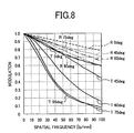
- Figs. 6 to 8 are graphs illustrating characteristics of an imaged spot (hereinafter, "spot characteristics") on the imaging device 16, with spatial frequency on the horizontal axis and MTF on the vertical axis.
- spot characteristics characteristics of an imaged spot
- characteristic lines are plotted, which are obtained when light incidence angles with respect to an object (tilt with respect to the optical axis L) are set to 0 degree, 45 degrees, 60 degrees, 75 degrees, and 95 degrees, respectively.
- the characteristic lines indicated by "R” in Figs. 6 to 8 represent the spot characteristics in a radial direction (in a radiation direction) at the corresponding incidence angles.
- the graph shown in Fig. 6 illustrates the spot characteristics when an optical filter having a cutoff wavelength of 700 nanometers (hereinafter, "an optical filter of 700 nanometers”) is used.
- the graph shown in Fig. 7 illustrates the spot characteristics when an optical filter having a cutoff wavelength of 900 nanometers (hereinafter, “an optical filter of 900 nanometers”) is used.
- the graph shown in Fig. 8 illustrates the spot characteristics when the optical filter 13 is used.
- the optical filter of 950 nanometers when used, sufficient resolution is obtained only with light at the incidence angle of 45 degrees or smaller, that is, light around the optical axis L.
- the reason for this is as follows. Because the lateral chromatic aberration occurs due to wavelength difference, the effect of the lateral chromatic aberration is increased by the optical filter of 950 nanometers than by the optical filter of 700 nanometers, and because the imaging optical system 11 is structured to enable a wide field of view, the effect is further intensified in the area distant from the optical axis L. However, with the optical filter of 950 nanometers, the intensity of infrared light can be used, so that an image can be captured clearly even in a low-illuminance environment.
- the optical filter 13 in the imaging apparatus 10 is structured such that the optical filter of 700 nanometers and the optical filter of 950 nanometers are combined in accordance with the optical characteristics of the imaging optical system 11.
- the imaging optical system 11 has such characteristics that the effect of the lateral chromatic aberration is small in the area around the optical axis L, so that sufficient resolution can be assured in a captured image (see the characteristic line at 0 degree in Fig. 7 ) even when the area around the optical axis L, that is, the center area Ac, is structured to have the cutoff wavelength of 950 nanometers.
- the center area Ac is structured to have the cutoff wavelength of 950 nanometers while an image can be captured clearly in the center area Ac even in a low-illuminance environment.
- the optical filter 13 has such characteristics that the effect of the lateral chromatic aberration increases as the distance from the optical axis L increases, so that the effect of the lateral chromatic aberration in a captured image can be reduced (see the characteristic lines at 45 degrees to 95 degrees in Fig. 8 ) by structuring the area distant from the optical axis L, that is, the peripheral area Ap, to have the cutoff wavelength of 700 nanometers.
- the spot characteristics similar to that of the optical filter of 700 nanometers as shown in Fig. 8 can be obtained. Therefore, the sufficient resolution can be obtained with the spatial frequency of 100 lp/mm regardless of the light incidence angle. Furthermore, with the optical filter 13, the intensity of infrared light can be used in the center area Ac. Therefore, the center area of an image, can be captured clearly.
- the image processing unit 12 is controlled by the control unit 100 that outputs necessary signals to the other units in a pipeline manner.
- the control unit 100 controls the image processing unit 12 and the mechanical units based on an operation performed via the operating unit 15.
- the imaging device 16 converts an object image formed by the imaging optical system 11 into electrical signals (the Bayer RGB pixel data) and then outputs the electrical signals.
- the imaging device 16 sequentially outputs each piece of the Bayer RGB pixel data based on coordinate data (x, y) notified by the control unit 100.
- the control unit 100 sequentially sends the coordinate data (x, y), which is to be notified to the imaging device 16, to subsequent stages at a predetermined time interval.
- the AGC circuit 110 amplifies an analog image signal received from the imaging device 16 to a predetermined level, and sends the amplified signal to the A/D converting unit 120.
- the amount of gain to be adjusted by the AGC circuit 110 is set to an appropriate value in consideration of a balance between required brightness of a screen and noise that are traded off against each other. Because the imaging apparatus 10 has the optical filter 13 that allows the infrared light to pass through the area around the optical axis L, the amount of gain to be raised with low illuminance can be reduced. Therefore, high-quality images with reduced noise can be obtained.
- the A/D converting unit 120 converts the analog signal of each piece of the Bayer RGB pixel data amplified by the AGC circuit 110 into a digital signal, and sends the digital signal to the Bayer interpolating unit 130.
- the digital signal of each piece of the Bayer RGB pixel data is 8-bit based.
- the Bayer interpolating unit 130 Upon receiving the digital signal of each piece of the Bayer RGB pixel data, the Bayer interpolating unit 130 generates color-component pixel data at all coordinate positions with respect to each of RGB color components by liner interpolation based on the received Bayer RGB pixel data.
- the color-component pixel data generated by Bayer interpolation is referred to as "Bayer-interpolated RGB pixel data”.
- the Bayer interpolating unit 130 sends the Bayer-interpolated RGB pixel data to the lateral-chromatic-aberration correcting unit 140.
- Bayer interpolation is performed in the following manner.
- Figs. 9A to 9D are schematic diagrams for explaining Bayer interpolation. More particularly, Fig.
- FIG. 9A is a schematic diagram of Bayer color filter array
- Fig. 9B is a schematic diagram of a resulting pattern of G-color component pixel data by Bayer interpolation
- Fig. 9C is a schematic diagram of a resulting pattern of R-color component pixel data by Bayer interpolation
- Fig. 9D is a schematic diagram of a resulting pattern of B-color component pixel data by Bayer interpolation.
- An area G 0 in Fig. 9B corresponds to an area indicated by either R or B in Fig. 9A .
- areas R 2 , R 4 , R 6 , R 8 , and R 0 in Fig. 9C correspond to areas indicated by either G or B in Fig. 9A .
- R 4 R 3 + R 5 / 2
- R 6 R 5 + R 7 / 2
- R 8 R 1 + R 7 / 2
- R 0 R 1 + R 3 + R 5 + R 7 / 4
- areas B 2 , B 4 , B 6 , B 8 , and B 0 in Fig. 9D correspond to areas indicated by either G or R in Fig. 9A .
- the areas B 2 , B 4 , B 6 , B 8 , and B 0 can be obtained in the same manner as the areas R 2 , R 4 , R 6 , R 8 , and R 0 (Equations (2) to (6)), and therefore, detailed explanation is omitted.
- the lateral-chromatic-aberration correcting unit 140 Upon receiving the Bayer-interpolated RGB pixel data, the lateral-chromatic-aberration correcting unit 140 performs coordinate transformation (coordinate transformation for lateral chromatic aberration) on the Bayer-interpolated RGB pixel data with respect to each of the RGB color components by using a predetermined polynomial. Then, the lateral-chromatic-aberration correcting unit 140 sends RGB pixel data on which the lateral chromatic aberration has been corrected through the coordinate transformation (hereinafter, "chromatic-aberration-corrected RGB pixel data") to the MTF correcting unit 150. Details about the lateral-chromatic-aberration correcting unit 140 will be given later with explanation about the distortion correcting unit 160.
- a memory with low capacity and low latency or a memory with low capacity and multiple ports e.g., static random access memory (SRAM)
- the MTF correcting unit 150 Upon receiving the chromatic-aberration-corrected RGB pixel data, the MTF correcting unit 150 performs an MTF correction process on the chromatic-aberration-corrected RGB pixel data by using a finite impulse response (FIR) filter 154. Then, the MTF correcting unit 150 outputs RGB pixel data on which the MTF correction has been performed (hereinafter, "MTF-corrected RGB pixel data").
- the MTF correction process is performed as follows.
- Fig. 10 is a schematic diagram of the MTF correcting unit 150.
- Fig. 11 is a schematic diagram for explaining coefficients of the FIR filter 154.
- the MTF correcting unit 150 includes a converting unit 152, the FIR filter 154, and an inverse converting unit 156.
- the converting unit 152 sends a luminance signal Y of the YCbCr pixel data to the FIR filter 154, and sends a color-difference signal CbCr of the YCbCr pixel data to the inverse converting unit 156.
- the FIR filter 154 performs a predetermined MTF correction process on the input luminance signal Y, and sends the luminance signal Y on which the MTF correction is performed (hereinafter, "MTF-corrected luminance signal Y") to the inverse converting unit 156. Because the FIR filter 154 (the MTF correcting unit 150) performs filtering (MTF correction) only on the luminance signal Y, it is possible to obtain high-quality images in which color noise is not amplified. In the embodiment, it is assumed that the FIR filter 154 is structured as a 5 ⁇ 5 filter, and coefficients such as coefficients as shown in Fig. 11 are set in the FIR filter 154.
- the inverse converting unit 156 performs inverse conversion on the MTF-corrected luminance signal Y received from the FIR filter 154 and on the color-difference signal CbCr that is corresponding to the MTF-corrected luminance signal Y among the color-difference signal CbCr received from the converting unit 152, so that inversely-converted RGB pixel data can be obtained.
- the inverse conversion is performed by using Equations (10) to (12).
- R Y + 1.402 Cr
- G Y ⁇ 0.714 Cr ⁇ 0.344
- Cb B Y + 1.772 Cb
- the inverse converting unit 156 sends the inversely-converted RGB pixel data to the distortion correcting unit 160.
- a focus spot on an imaging device degrades as a distance of the focus spot from an optical axis increases, resulting in degrading quality of a captured image (see Figs. 6 and 7 ).
- the FIR filter can be set differently depending on the distance from the optical axis (different coefficients are set)
- high-quality images can be captured effectively.
- the imaging apparatus 10 has the optical filter 13 structured so that different cutoff wavelength characteristics can be obtained depending on the distance from the optical axis (the center area Ac and the peripheral area Ap), it is possible to prevent degradation in resolving power in an area corresponding to the peripheral area Ap in a captured image (see Fig. 8 ). Therefore, even when the single FIR filter 154 (or a single coefficient) is used, the imaging apparatus 10 can enhance the effect of the MTF correction.
- the distortion correcting unit 160 performs a distortion correction on the MTF-corrected RGB pixel data, on which the lateral chromatic aberration correction has been performed and then the MTF correction has been performed, by performing coordinate transformation (distortion coordinate transformation) collectively for all the RGB color components by using a predetermined polynomial. Then, the distortion correcting unit 160 sends RGB pixel data on which the distortion correction has been performed (hereinafter, "distortion-corrected RGB pixel data") to the gamma correcting unit 170.
- a memory having a larger capacity (corresponding to one screen at a maximum) than that of the memory used for lateral chromatic aberration correction but having only a single port is necessary. Therefore, a memory with high latency (for example, a dynamic random access memory (DRAM)) can be used. Details about the distortion correcting unit 160 will be described later.
- the gamma correcting unit 170 performs a predetermined gamma correction on the distortion-corrected RGB pixel data depending on characteristics of the monitor 14 by using a lookup table or the like provided for each of the RGB color components. Then, the gamma correcting unit 170 sends RGB pixel data on which the gamma correction has been performed to the monitor 14.
- the image processing unit 12 performs the image processing process.
- Detailed explanation about the lateral-chromatic-aberration correcting unit 140 and the distortion correcting unit 160 are now given in the following description.
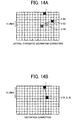
- Fig. 12 is a schematic diagram for explaining lateral chromatic aberration and distortion on a screen displayed on the monitor 14 (the imaging plane 16a of the imaging device 16).
- Fig. 13 is a schematic diagram for explaining a conventional method of correcting the lateral chromatic aberration and the distortion.
- Fig. 14A is a schematic diagram for explaining a method of correcting the lateral chromatic aberration by the imaging apparatus 10.
- Fig. 14B is a schematic diagram for explaining a method of correcting the distortion by the imaging apparatus 10.
- pixel data is formed at a position (pixel) 1 on the upper right portion in the screen when an image is captured by using an optical system that does not cause lateral chromatic aberration and distortion.
- the pixel data at the position 1 on the upper right portion in the screen shifts to positions (pixels) 2(R), 3(G), and 4(B) with respect to each of RGB color components.
- Such positional shift occurs because of the distortion, and the amount of shift varies for each of the RGB color components because of the lateral chromatic aberration.
- the amount of the distortion and the amount of the lateral chromatic aberration can be determined based on design data of the optical system, so that it is possible to calculate positions to which the RGB color components shift, respectively, from the original position.
- R-color component pixel data at the position 2(R), G-color component pixel data at the position 3(G), and B-color component pixel data at the position 4(B) are copied to the position 1 that is the original position.
- coordinate transformation is performed so that the lateral chromatic aberration and the distortion can be corrected simultaneously.
- the imaging apparatus 10 corrects the lateral chromatic aberration and the distortion separately as described above. This is because the lateral chromatic aberration occurs such that the amount of shift varies depending on the color components (wavelength difference) while the amount of shift is small, and the distortion occurs such that the amount of shift is large while a shift direction and the amount of shift are the same between the color components. Specifically, the imaging apparatus 10 performs coordinate transformation individually on pixel data of each of the RGB color components to correct the lateral chromatic aberration, and then performs coordinate transformation collectively on the pixel data of each of the RGB color components after the lateral chromatic aberration has been corrected.
- a memory used for performing the coordinate transformation by the image processing unit 12 can be separated into a memory used for correcting the lateral chromatic aberration (a first coordinate transformation memory) and a memory used for correcting the distortion (a second coordinate transformation memory) in the following manner.
- the first coordinate transformation memory is structured as a low-capacity high-speed (low-latency or multi-port) memory so that it can be used individually for each of the RGB color components.
- the second coordinate transformation memory is structured as a high-capacity low-speed (high-latency or single-port) memory so that it can be used in common to all the RGB color components.
- overall costs can be reduced.
- the lateral-chromatic-aberration correcting unit 140 copies the R-color component pixel data at the position 2(R), the B-color component pixel data at the position 4(B), and the G-color component pixel data at the position 3(G) among pieces of RGB pixel data sent by the Bayer interpolating unit 130 to the position 3(G).
- the lateral-chromatic-aberration correcting unit 140 does not perform the coordinate transformation on the G-color component pixel data.
- the chromatic-aberration corrected RGB pixel data is generated.
- the distortion correcting unit 160 performs the coordinate transformation collectively on all pieces of the chromatic-aberration corrected RGB pixel data at the position 3(G) so that they are copied to the position 1 that is the original position. As a result, the distortion is corrected.
- the distortion correcting unit 160 performs the distortion correction on the MTF-corrected RGB pixel data that is obtained after the lateral-chromatic-aberration correcting unit 140 performs the lateral chromatic aberration correction and then the MTF correcting unit 150 performs the MTF correction. Because the MTF correction is not performed through the coordinate transformation unlike the lateral chromatic aberration correction and the distortion correction, even when the distortion correction is performed on the MTF-corrected RGB pixel data, adverse effects can hardly occur while desired effects can be assured as follows.
- the MTF correcting unit 150 performs the MTF correction by performing filtering only on the luminance signal Y
- the MTF correction (by the MTF correcting unit 150) needs to be performed after the lateral chromatic aberration correction (by the lateral-chromatic-aberration correcting unit 140). From this view point, it seems applicable to perform the MTF correction after the distortion correction (by the distortion correcting unit 160).
- a transformation distance by the coordinate transformation for the distortion correction is long, so that calculation error may sometimes occur.
- a high-speed memory for only 3 lines is sufficient for each of the RGB color components to perform the lateral chromatic aberration correction.
- a memory for 5 lines is necessary but the memory can be commonly used for all the RGB color components and the memory can be a low-speed memory. Therefore, overall costs can be reduced compared with the conventional method shown in Fig. 13 .
- the distortion described in the embodiment indicates distortion of a lens with respect to a desired projection type.
- the projection type can be one in which a looked-down image viewed from the top portion of a camera is obtained, or in which an enlarged view of a specific portion is displayed.
- Fig. 15 is a schematic diagram of the lateral-chromatic-aberration correcting unit 140.
- the lateral-chromatic-aberration correcting unit 140 includes a chromatic-aberration-correction coordinate transformation memory 142 (hereinafter, "the coordinate transformation memory 142") ("SRAM” in Fig. 15 ), a chromatic-aberration-correction coordinate transformation calculating unit 144 (hereinafter, “the calculating unit 144"), and a coordinate-transformation coefficient table 146.
- the coordinate transformation memory 142 is a line buffer and mounted for each of the RGB color components.
- the coordinate transformation memory 142 for the R-color component is referred to as a coordinate transformation memory 142(R)
- the coordinate transformation memory 142 for the G-color component is referred to as a coordinate transformation memory 142(G)
- the coordinate transformation memory 142 for the B-color component is referred to as a coordinate transformation memory 142(B).
- Each of the coordinate transformation memories 142(R), 142(G), and 142(B) includes a control unit (not shown) for reading and writing data.
- each of the coordinate transformation memories 142(R), 142(G), and 142(B) is configured as an SRAM for 20 lines based on assumption that the maximum amount of shift due to the lateral chromatic aberration is 20 lines in the Y-direction.
- the size in the X-direction is determined based on resolution. For example, when the resolution is set to video graphic array (VGA) of 640x480, the size in the X-direction equals to 640 dots.
- VGA video graphic array
- each of the coordinate transformation memories 142(R), 142(G), and 142(B) performs writing and reading 8-bit data.
- each of the coordinate transformation memories 142(R), 142(G), and 142(B) has low capacity, it is preferable to assure a memory area for 20 lines by using an SRAM that has three ports and is mounted on an image processing chip in the imaging apparatus 10.
- an SRAM that has three ports and is mounted on an image processing chip in the imaging apparatus 10.
- a memory with low latency such as an SRAM, it is applicable to perform time sharing so that a memory having a single port can be used as a memory having three ports.
- the calculating unit 144 calculates transformed coordinates for the lateral chromatic aberration correction for each of the RGB color components based on a predetermined coordinate transformation equation.
- the coordinate-transformation coefficient table 146 contains coefficients for the coordinate transformation equation used by the calculating unit 144.
- Pixel data of each of the RGB color components of a captured image in which lateral chromatic aberration and distortion occur is written in each of the coordinate transformation memories 142(R), 142(G), and 142(B) based on the coordinate data (x, y) in sequence from the first line.
- the pieces of the pixel data for 20 lines are written in each of the coordinate transformation memories 142(R), 142(G), and 142(B)
- the pieces of the pixel data are discarded in sequence from the first line, and then pieces of pixel data of subsequent lines are written.
- pieces of the pixel data for the RGB color components for 20 lines at maximum for the coordinate transformation for correcting the lateral chromatic aberration are sequentially stored in each of the coordinate transformation memories 142(R), 142(G), and 142(B).
- the coordinate data (x, y) indicates a reading position of a captured image for one frame.
- each of the coordinate transformation memories 142(R), 142(G), and 142(B) is a line buffer for 20 lines, a writing line is cyclically changed. Accordingly, the coordinate data (x, y) cannot be used as a writing address for each of the coordinate transformation memories 142(R), 142(G), and 142(B), so that it is necessary to convert a value of the coordinate data (x, y) into a real address for each of the coordinate transformation memories 142(R), 142(G), and 142(B).
- a configuration used for this conversion is omitted in the configuration shown in Fig. 15 . The same is applied to a relationship between transformed coordinate data (X, Y) and a reading address for each of the coordinate transformation memories 142(R), 142(G), and 142(B) during a reading operation, which will be described later.
- the calculating unit 144 receives input of the coordinate data (x, y) and calculates transformed coordinate for the lateral chromatic aberration correction for each of the RGB color components based on a predetermined coordinate transformation equation such as a polynomial. Then, the calculating unit 144 outputs the transformed coordinate data (X, Y) for each of the RGB color components. As described above, in the embodiment, the coordinate transformation is performed on the R-color component pixel data and the B-color component pixel data such that they are copied to the position of the G-color component pixel data.
- the calculating unit 144 outputs the input coordinate data (x, y) as the transformed coordinate data (X, Y) for the G-color component pixel data, while the calculating unit 144 converts pieces of the input coordinate data (x, y) into pieces of the transformed coordinate data (X, Y) for the R-color component pixel data and the B-color component pixel data by using a predetermined coordinate transformation equation and outputs the pieces of the transformed coordinate data (X, Y).
- the above operation is repeated for each piece of the coordinate data (x, y).
- the pieces of the transformed coordinate data (X, Y) for the R-color component pixel data and the B-color component pixel data are different from each other.
- Equation (13) The coordinate transformation equation is represented by Equation (13), when a center point of the screen is assumed to be an original point.
- abs(numeral) is an absolute value
- a(1) to a(4) and b(1) to b(4) are coefficients of coordinate transformation.
- the coefficients of coordinate transformation are stored in advance in the coordinate-transformation coefficient table 146.
- the coordinate-transformation coefficient table 146 is provided for each of different areas, although only one of them is shown in Fig. 15 . This is because, while the imaging apparatus 10 has the optical filter 13 in which the different upper limits of the transmitting wavelength are set depending on the distance from the optical axis L, the lateral chromatic aberration needs to be corrected depending on the different upper limits. As described above, the optical filter 13 has the center area Ac having the cutoff wavelength of 950 nanometers and the peripheral area Ap having the cutoff wavelength of 700 nanometers.
- the central wavelength in the R-color component pixel data shifts towards the long wavelength band compared with that in the peripheral area Ap, and the amount of shift of the R-color component pixel data due to the lateral chromatic aberration changes depending on the displacement of the central wavelength.
- the displacement of the central wavelength occurs because the imaging device 16 has sensitivity to the infrared light in addition to the visible light. Specifically, in the example shown in Fig.
- the R-color component pixel data shifts to the position 2(R) due to the lateral chromatic aberration because of the cutoff wavelength of 700 nanometers
- the R-color component pixel data shifts to a position 2'(R) due to the lateral chromatic aberration because of the cutoff wavelength of 950 nanometers.
- the position to which pixel data of each of the RGB color components shifts can be determined by calculating the amount of shift from the original position because the amount of the distortion and the amount of the lateral chromatic aberration can be determined based on the design data of the imaging optical system 11.
- a difference in shift positions due to the lateral chromatic aberration in an object image formed with light that has passed through the optical filter 13 can be determined by calculating the amount of shift from the original position, because the amount of the lateral chromatic aberration corresponding to a light wavelength band to be examined can be obtained based on the design data of the imaging optical system 11, a cutoff wavelength of the optical filter 13, and a sensitivity range of the imaging device 16.
- a set of coefficients of the coordinate transformation a 1 (1) to a 1 (4) and b 1 (1) to b 1 (4) corresponding to the center area Ac and a set of coefficients of the coordinate transformation a 2 (1) to a 2 (4) and b 2 (1) to b 2 (4) corresponding to the peripheral area Ap are stored in the coordinate-transformation coefficient tables 146 separately. Accordingly, the coordinate-transformation coefficient table 146 (the coefficients of coordinate transformation) corresponding to each of the center area Ac and the peripheral area Ap is used as appropriate.
- each of the coordinate transformation memories 142(R), 142(G), and 142(B) the reading operation is performed, in parallel with the writing operation as described above (to be precise, after a predetermined time elapses), for sequentially reading pixel data of each of the RGB color components based on the transformed coordinate data (X, Y) for each of the RGB color components output by the calculating unit 144 (to be precise, a value obtained by performing address transformation on the transformed coordinate data (X, Y)).
- the coordinate transformation memory 142(G) reads the G-color component pixel data at the position same as that to which the G-color component pixel data is written.
- the coordinate transformation memories 142(R) and 142(G) read the R-color component pixel data and the B-color component pixel data, respectively, at positions shifted by a predetermined amount from the positions to which the R-color component pixel data and the B-color component pixel data are written, that is, at the positions shifted by the amount due to the lateral chromatic aberration.
- each of the coordinate transformation memories 142(R), 142(G), and 142(B) outputs pixel data of each of the RGB color components on which the lateral chromatic aberration has been corrected (the RGB pixel data obtained by correcting positional shifts between each of the RGB color components caused by the lateral chromatic aberration).
- the process performed by the lateral-chromatic-aberration correcting unit 140 corresponds to a lateral chromatic aberration correction process
- the coordinate transformation memory 142 corresponds to the first coordinate transformation memory used for the lateral chromatic aberration correction process.
- Figs. 16A to 16C are schematic diagrams of modifications of the calculating unit 144. More particularly, Fig. 16A is a schematic diagram of a chromatic-aberration correcting unit 1441, Fig. 16B is a schematic diagram of a chromatic-aberration correcting unit 1442, and Fig. 16C is a schematic diagram of a chromatic-aberration correcting unit 1443.
- the chromatic-aberration correcting unit 1441 does not perform coordinate transformation on the G-color component, and outputs the input coordinate data (x, y) as the transformed coordinate data (X, Y) for the G-color component.
- a coordinate transformation calculating unit 1441a converts the input coordinate data (x, y) into the transformed coordinate data (X, Y) for the R-color component, and outputs the transformed coordinate data (X, Y).
- a coordinate transformation calculating unit 1441b converts the input coordinate data (x, y) into the transformed coordinate data (X, Y) for the B-color component, and outputs the transformed coordinate data (X, Y).
- the chromatic-aberration correcting units 1442 and 1443 shown in Figs. 16B and 16C are configured based on the fact that the R-color component and the B-color component are generally shifted symmetrically with respect to the G-color component due to the lateral chromatic aberration (see Fig. 12 ).
- a coordinate transformation calculating unit 1442a calculates a correction amount of the coordinate data (x, y).
- a subtracting unit 1442b obtains a value by subtracting the correction amount from the coordinate data (x, y), so that the transformed coordinate data (X, Y) for the B-color component can be obtained.
- An adding unit 1442c obtains a value by adding the correction amount to the coordinate data (x, y), so that the transformed coordinate data (X, Y) for the R-color component data can be obtained.
- the chromatic-aberration correcting unit 1442 outputs the coordinate data (x, y) as the transformed coordinate data (X, Y) for the G-color component without performing coordinate transformation.
- the chromatic-aberration correcting unit 1443 is configured so that the symmetrical positions can be considered while the same configuration as that of the chromatic-aberration correcting unit 1442 is maintained. Furthermore, the chromatic-aberration correcting unit 1443 includes a gain circuit 1443a so that the correction amount for the R-color component can be adjusted. The gain amount can be set differently depending on each area. The gain circuit 1443a can be configured to adjust the correction amount for the B-color component. In each of the chromatic-aberration correcting units 1442 and 1443, only one coordinate transformation calculating unit is necessary, so that the size of a corresponding circuit can be more reduced.
- the chromatic-aberration correcting unit 1441 can be configured to have a lookup table (LUT) containing correspondence between the coordinate data (x, y) to be input and the transformed coordinate data (X, Y) to be output for each of the R-color component and the B-color component, instead of the coordinate transformation calculating units 1441a and 1441B, so that the transformed coordinate data (X, Y) corresponding to the coordinate data (x, y) can be directly obtained from the LUT.
- LUT lookup table
- each of the chromatic-aberration correcting units 1442 and 1443 can be configured to have an LUT containing correspondence between the input coordinate data (x, y) and the correction amount, instead of the coordinate transformation calculating unit 1442a, so that the correction amount corresponding to the coordinate data (x, y) can be directly obtained from the LUT.
- the calculations for the coordinate transformation can be omitted, so that the lateral chromatic aberration correction can be performed by using only a memory chip.
- Fig. 17 is a schematic diagram of the distortion correcting unit 160.
- the distortion correcting unit 160 includes an RGB compositing unit 161, a distortion-correction coordinate transformation memory (frame memory) 162 (hereinafter, “the coordinate transformation memory 162”), an RGB separating unit 163, a distortion-correction coordinate transformation calculating unit 164 (hereinafter, “the calculating unit 164"), and a coordinate-transformation coefficient table 165.
- the RGB compositing unit 161 composites three pieces of pixel data of the RGB color components into a single piece of composite RGB pixel data.
- the coordinate transformation memory 162 stores therein the composite RGB pixel data used for the distortion correction, and is commonly used for all the RGB color components.
- the coordinate transformation memory 162 includes a control unit (not shown) that controls writing and reading of data.
- the RGB separating unit 163 separates the composite RGB pixel data into original color components, that is, three pieces of pixel data of the RGB color components.
- the calculating unit 164 calculates transformed coordinate for the distortion correction with respect to the composite RGB pixel data by using a predetermined coordinate transformation equation.
- the coordinate-transformation coefficient table 165 contains coefficients used for the coordinate transformation equation.
- a frame buffer having a capacity for storing pixel data corresponding to one screen at a maximum is used for the distortion correction process in the embodiment.
- a single frame buffer corresponding to total bit widths of pixel data of all the RGB color components can be used.
- the resolution is set to VGA of 640x480 and the number of bits (color depth) for pixel data of each of the RGB color components is set to 8 bits, so that a DRAM corresponding to 640x480 dots and capable of 24-bit based writing and reading is employed as the coordinate transformation memory 162.
- the coordinate transformation memory 162 is required to have a large capacity, it is difficult to mount an SRAM in the image processing chip in terms of costs. Furthermore, because a memory having only a single port for all the RGB color components is sufficient, a DRAM mounted outside of the image processing chip can be preferably used as the coordinate transformation memory 162.
- the RGB compositing unit 161 Upon sequentially receiving pieces of pixel data of each of the RGB color components (8-bit each) on which the lateral chromatic aberration correction has been performed (in the embodiment, the MTF correction has also been performed), the RGB compositing unit 161 composites the received pieces of the pixel data into a single piece of the composite RGB pixel data (24-bit), and outputs the composite RGB pixel data.
- the composite RGB pixel data is written in the coordinate transformation memory 162 in sequence from the first line based on the coordinate data (x, y).
- the calculating unit 164 Upon receiving the coordinate data (x, y), the calculating unit 164 calculates a common transformed coordinate for the distortion correction for the RGB color components by using the predetermined coordinate transformation equation such as polynomial, and outputs the transformed coordinate data (X, Y).
- the coordinate transformation equation can be represented by Equation (13) similar to the lateral chromatic aberration correction. However, coefficients of coordinate transformation for the distortion correction are different from those for the lateral chromatic aberration correction.
- the coefficients of coordinate transformation for the distortion correction are stored in the coordinate-transformation coefficient table 165 in advance.
- the reading operation is performed, in parallel with the writing operation on the composite RGB pixel data (24-bit) by the RGB compositing unit 161 (to be precise, after a predetermined time elapses), for sequentially reading the composite RGB pixel data based on the transformed coordinate data (X, Y) output by the calculating unit 164.
- the RGB separating unit 163 separates the composite RGB pixel data (24-bit) read from the coordinate transformation memory 162 into pixel data of each of the RGB color components (8-bit).
- the RGB separating unit 163 outputs the pixel data of each of the RGB color components on which the distortion correction, the lateral chromatic aberration correction, and the MTF correction have been performed.
- pixel data of each of the RGB color components is copied to the original position (x, y) (the position 1 in the examples shown in Figs. 15 , 17A, and 17B ).
- the process performed by the distortion correcting unit 160 corresponds to a distortion correction process
- the coordinate transformation memory 162 corresponds to the second coordinate transformation memory for the distortion correction process.
- the distortion correction process it is applicable to provide a lookup table (LUT) containing correspondence between the coordinate data (x, y) to be input and the transformed coordinate data (X, Y) to be output so that the transformed coordinate data (X, Y) corresponding to the coordinate data (x, y) can be directly obtained from the LUT.
- LUT lookup table
- the imaging apparatus 10 forms image data of an object image in an area corresponding to the center area Ac of the optical filter 13 with the infrared light as well as the visible light. Therefore, the imaging apparatus 10 can capture an easily-viewable image of an object even in a low-illuminance environment. Because the effect due to the lateral chromatic aberration is small in the center area Ac, that is, the area that is not distant from the optical axis L, sufficient resolution can be assured in the image data of the object image (see Fig. 8 ) formed with the infrared light. Therefore, degradation in the image of the object can hardly occur, assuring clear visibility of the image.
- the imaging apparatus 10 can capture a clear image in an area corresponding to an angle of view close to the optical axis (in the embodiment, the angle of view of 45 degrees or smaller, which corresponds to the center area Ac) even in a low-illuminance environment, e.g., during a nighttime, without using an additional mechanical changeover unit.
- the imaging apparatus 10 forms the image data of the object image only with the visible light without using the infrared light in an area corresponding to the peripheral area Ap of the optical filter 13, so that the effect of the lateral chromatic aberration can be reduced (see Fig. 8 ).
- the imaging apparatus 10 can reduce the effect of the lateral chromatic aberration, which generally increases as the distance from the optical axis L increases on the imaging plane because of the structure of the imaging optical system 11. As a result, increase in costs can be prevented.
- the imaging apparatus 10 can form a high-resolution image in an area corresponding to a wide angle of view when the image is captured in a normal imaging environment with high illuminance.
- the image processing unit 12 corrects the image data based on correction equation corresponding to the upper limit of the transmitting wavelength of the optical filter 13, that is, the correction equation corresponding to each of the cutoff wavelengths of the center area Ac and the peripheral area Ap of the optical filter 13. Therefore, a highly-clear image of the object can be obtained.
- the same correction equation (Equation (13)) can be used for both the center area Ac and the peripheral area Ap while only the coefficients are set differently (the coefficients of a 1 (1) to a 1 (4) and b 1 (1) to b 1 (4) are set for the center area Ac and the coefficients of a 2 (1) to a 2 (4) and b 2 (1) to b 2 (4) are set for the peripheral area Ap) in accordance with each of the cutoff wavelengths. Therefore, a highly-clear image of the object can be obtained with a simple structure.
- the lateral chromatic aberration in an image is corrected through the lateral chromatic aberration correction process (by the lateral-chromatic-aberration correcting unit 140), and then the distortion in the image is corrected through the distortion correction process (by the distortion correcting unit 160). Therefore, it is possible to appropriately and easily correct the lateral chromatic aberration and the distortion. As a result, highly-clear image of the object can be obtained. Because the distortion occurs such that each piece of pixel data shifts by the same amount regardless of wavelength, if the distortion correction is performed on image data on which the lateral chromatic aberration has already been corrected, the distortion can be appropriately corrected at one time for all pieces of the pixel data without correcting the distortion of each piece of the pixel data separately.
- the imaging apparatus 10 can be more preferably used when the imaging optical system 11 is structured to enable a wide angle of view. This is because, while the effects of the lateral chromatic aberration in an area distant from the optical axis L increase when the wide angle of view is enabled, the imaging apparatus 10 can effectively cope with such a situation.
- the first coordinate transformation memory (the coordinate transformation memory 142) for correcting the lateral chromatic aberration and the second coordinate transformation memory (the coordinate transformation memory 162) for correcting the distortion are separately arranged.
- the first coordinate transformation memory is structured as either an SRAM with low capacity and low latency or an SRAM with low capacity and multiple ports
- the second coordinate transformation memory is structured a DRAM with a single port, large capacity, and high latency so that the DRAM can be used in common to all color components. Therefore, costs can be reduced. With this configuration, the following problems in the conventional technology can be resolved.
- the coordinate transformation is performed separately on pixel data of each of the RGB color components to correct the lateral chromatic aberration and the distortion simultaneously, so that it is necessary to mount either a large-capacity memory with low latency at the time of random access or a large-capacity memory having multiple ports, such as an SRAM, for each of the RGB color components.
- a large-capacity memory with low latency at the time of random access or a large-capacity memory having multiple ports, such as an SRAM, for each of the RGB color components.
- a memory the large-capacity SRAM or the memory having multiple ports
- cost of an apparatus that enables high resolution by using a large-capacity memory increases.
- the imaging apparatus 10 can correct the lateral chromatic aberration while preventing increase in costs. Furthermore, it is possible to obtain a highly-clear image of the object even in a low-illuminance environment.
- the optical filter 13 has the center area Ac having the cutoff wavelength of 950 nanometers and the peripheral area Ap having the cutoff wavelength of 700 nanometers.
- the configuration of the optical filter 13 is not limited to the above example as long as the optical filter 13 is structured so that the upper limit of the transmitting wavelength decreases as the distance from the optical axis L increases such that infrared light is allowed to pass through an area corresponding to the optical axis L and is not allowed to pass through an area most distant from the optical axis L.
- the optical filter can have three or more areas having different upper limits of the transmitting wavelength in a concentric manner with respect to the optical axis L.
- the optical filter such that the upper limit of the transmitting wavelength is continuously reduced as the distance from the optical axis L increases.
- the cutoff wavelength (the upper limit of the transmitting wavelength) of an area most distant from the optical axis L (the peripheral area Ap) in the optical filter 13 is set to 700 nanometers, which is known as a boundary wavelength between the visible region and the infrared region, so that the infrared light can be cut off.
- the cutoff wavelength is not limited to the boundary wavelength of 700 nanometers as long as the infrared light can be cut off practically so that the viewability of a captured image can be assured without degradation due to the effect of the lateral chromatic aberration.
- the imaging device needs to detect a red-color component to form a color captured image, it is preferable to set the cutoff wavelength of the area most distant from the optical axis L (the peripheral area Ap) in consideration of the wavelength necessary for detecting a wavelength of a red-color component and the wavelength that must be cut off to assure the viewability of the captured image without degradation due to the effect of the lateral chromatic aberration.
- the imaging device 16 has a color filter having Bayer color filter array
- the present invention is not limited to this example.
- the imaging device can have a color filter having CMYK array, RGB+Ir (infrared) array, or the like.
- CMYK array CMYK array
- RGB+Ir (infrared) array or the like.
- the imaging device having four-color filter array either a memory with lower latency or a RAM having four ports is necessary for performing the lateral chromatic aberration correction. Therefore, compared with a case in which three RGB colors are used as in the embodiment, the effects obtained by separately mounting the coordinate transformation memory for the lateral chromatic aberration correction and the coordinate transformation memory for the distortion correction can be more enhanced.
- the present invention is not limited to this configuration as long as image data can be corrected based on the correction equation corresponding to the upper limit of the transmitting wavelength set in the optical filter.
- the effect of the lateral chromatic aberration which increases as the distance from the optical axis increases in the imaging optical system, can be reduced by using the optical filter structured such that the upper limit of the transmitting wavelength decreases as the distance from the optical axis increases. Furthermore, the light intensity available by the imaging device increases as the distance from the optical axis decreases, so that highly-clear image can be captured in a low-illuminance environment.
Landscapes
- Physics & Mathematics (AREA)
- Engineering & Computer Science (AREA)
- General Physics & Mathematics (AREA)
- Multimedia (AREA)
- Signal Processing (AREA)
- Optics & Photonics (AREA)
- Theoretical Computer Science (AREA)
- Spectroscopy & Molecular Physics (AREA)
- Color Television Image Signal Generators (AREA)
- Blocking Light For Cameras (AREA)
- Image Processing (AREA)
- Studio Devices (AREA)
Claims (9)
- Appareil de formation d'image comprenant :un dispositif de formation d'image (16) qui a une sensibilité à la lumière dans les régions visible et infrarouge ;un système optique de formation d'image (11), qui forme une image d'un objet sur le dispositif de formation d'image (16) et qui est structuré pour obtenir un large champ de vision de plus de 90° par rapport à un axe optique du système optique de formation d'image (11) ;un filtre optique (13) agencé entre le système optique de formation d'image (11) et le dispositif de formation d'image (16) qui est configuré pour transmettre les longueurs d'onde jusqu'à une limite supérieure ; etune unité de traitement d'image (12) qui génère des données d'image sur la base d'un signal de sortie délivré par le dispositif de formation d'image (16), caractérisé en ce quele filtre optique (13) est structuré de sorte que la limite supérieure des longueurs d'onde de transmission diminue alors qu'une distance par rapport à l'axe optique du système optique de formation d'image (11) augmente, de sorte que le filtre optique (13) est configuré pour transmettre une lumière infrarouge au niveau de l'axe optique et pour bloquer la lumière infrarouge à une position qui est la plus éloignée de l'axe optique.
- Appareil de formation d'image selon la revendication 1, dans lequel
le filtre optique (13) est structuré de sorte qu'une limite supérieure d'une longueur d'onde de transmission diminue graduellement alors qu'une distance par rapport à un axe optique du système optique de formation d'image (11) augmente. - Appareil de formation d'image selon la revendication 1, dans lequel
l'unité de traitement d'image (12) est configurée pour corriger les données d'image sur la base d'une équation de correction correspondant à la limite supérieure de la longueur d'onde de transmission du filtre optique (13), qui dépend de la distance par rapport à l'axe optique. - Appareil de formation d'image selon la revendication 3, dans lequel le filtre optique (13) comporte une pluralité de zones présentant chacune une limite supérieure différente de la longueur d'onde de transmission d'une manière concentrique par rapport à l'axe optique.
- Appareil de formation d'image selon la revendication 3 ou 4, dans lequel l'équation de correction est utilisée pour corriger une aberration chromatique latérale correspondant à une plage de longueur d'onde prise en charge par le système optique de formation d'image (11).
- Appareil de formation d'image selon l'une quelconque des revendications 3 à 5, dans lequel l'unité de traitement d'image (12) comprend :une première unité de correction (140) qui corrige l'aberration chromatique latérale des données d'image sur la base de l'équation de correction, etune deuxième unité de correction (160) qui corrige une distorsion des données d'image obtenues après que l'aberration chromatique latérale a été corrigée par la première unité de correction (140).
- Appareil de formation d'image selon la revendication 6, dans lequel l'unité de traitement d'image (12) comprend en outre :une première mémoire de transformation de coordonnées (142) pour la première unité de correction (140), etune deuxième mémoire de transformation de coordonnées (162) pour la deuxième unité de correction (160).
- Appareil de formation d'image selon la revendication 1 ou 2, dans lequel
l'unité de traitement d'image (12) corrige une aberration des données d'image sur la base d'une équation de correction correspondant à la limite supérieure de la longueur d'onde de transmission. - Procédé de correction d'image en utilisant un appareil de formation d'image selon la revendication 1 ou 2, le procédé de correction d'image comprenant :la génération de données d'image sur la base d'un signal de sortie du dispositif de formation d'image (16) ; etla correction d'une aberration des données d'image sur la base d'une équation de correction correspondant à la limite supérieure de la longueur d'onde de transmission.
Applications Claiming Priority (1)
| Application Number | Priority Date | Filing Date | Title |
|---|---|---|---|
| JP2008132892A JP5010533B2 (ja) | 2008-05-21 | 2008-05-21 | 撮像装置 |
Publications (2)
| Publication Number | Publication Date |
|---|---|
| EP2133238A1 EP2133238A1 (fr) | 2009-12-16 |
| EP2133238B1 true EP2133238B1 (fr) | 2016-03-23 |
Family
ID=41129146
Family Applications (1)
| Application Number | Title | Priority Date | Filing Date |
|---|---|---|---|
| EP09251295.3A Not-in-force EP2133238B1 (fr) | 2008-05-21 | 2009-05-12 | Appareil d'imagerie et procédé de correction d'images |
Country Status (3)
| Country | Link |
|---|---|
| US (1) | US8368968B2 (fr) |
| EP (1) | EP2133238B1 (fr) |
| JP (1) | JP5010533B2 (fr) |
Families Citing this family (13)
| Publication number | Priority date | Publication date | Assignee | Title |
|---|---|---|---|---|
| JP5570373B2 (ja) * | 2010-09-29 | 2014-08-13 | 富士フイルム株式会社 | 内視鏡システム |
| JP5244164B2 (ja) * | 2010-10-18 | 2013-07-24 | 富士フイルム株式会社 | 内視鏡装置 |
| KR101691156B1 (ko) * | 2010-12-14 | 2016-12-30 | 삼성전자주식회사 | 조명 광학계와 결상 광학계가 통합된 광학계 및 이를 포함하는 3차원 영상 획득 장치 |
| US8861852B2 (en) * | 2011-05-09 | 2014-10-14 | Canon Kabushiki Kaisha | Image processing method for image restoration, image processing apparatus and image pickup apparatus |
| CN103688536B (zh) * | 2011-05-30 | 2016-05-11 | 株式会社尼康 | 图像处理装置、图像处理方法 |
| US20130321675A1 (en) * | 2012-05-31 | 2013-12-05 | Apple Inc. | Raw scaler with chromatic aberration correction |
| JP5929567B2 (ja) * | 2012-07-03 | 2016-06-08 | ソニー株式会社 | 画像信号処理装置、および画像信号処理方法、並びにプログラム |
| CN105093523B (zh) * | 2015-09-11 | 2017-10-31 | 哈尔滨工业大学 | 多尺度多孔径光学成像系统 |
| WO2017158690A1 (fr) * | 2016-03-14 | 2017-09-21 | リアロップ株式会社 | Dispositif de traitement d'image, procédé de traitement d'image, support d'enregistrement, programme et dispositif de capture d'image |
| CN106560738B (zh) * | 2016-06-02 | 2019-06-11 | 河南科技大学 | 一种完美ig涡旋光束的产生装置及产生方法 |
| EP3285116B1 (fr) | 2016-08-17 | 2020-07-08 | Leica Instruments (Singapore) Pte. Ltd. | Dispositif d'iris multispectral |
| JP6975897B2 (ja) * | 2016-12-27 | 2021-12-01 | パナソニックIpマネジメント株式会社 | 画像生成装置及び撮像装置 |
| JP6966934B2 (ja) * | 2017-03-29 | 2021-11-17 | パナソニックIpマネジメント株式会社 | 画像生成装置及び撮像装置 |
Family Cites Families (16)
| Publication number | Priority date | Publication date | Assignee | Title |
|---|---|---|---|---|
| JPH06148593A (ja) * | 1992-11-11 | 1994-05-27 | Canon Inc | 光量調整装置を有した光学系 |
| JPH1147084A (ja) * | 1997-07-30 | 1999-02-23 | Olympus Optical Co Ltd | 内視鏡用撮像ユニット |
| US6091451A (en) | 1997-08-19 | 2000-07-18 | Hewlett-Packard Company | Digital imaging system having an anti color aliasing filter |
| JPH11316405A (ja) | 1998-04-30 | 1999-11-16 | Koito Ind Ltd | 車両撮像装置 |
| JP2001268583A (ja) | 2000-03-17 | 2001-09-28 | Olympus Optical Co Ltd | 撮像装置及び撮像光学系 |
| JP2002253500A (ja) * | 2001-03-05 | 2002-09-10 | Olympus Optical Co Ltd | 内視鏡用光源装置 |
| JP4419363B2 (ja) | 2001-12-13 | 2010-02-24 | 株式会社ニコン | 波長選択素子を備えた撮像装置 |
| JP3981034B2 (ja) * | 2003-03-25 | 2007-09-26 | 富士フイルム株式会社 | カラー画像取得装置およびカラー電子カメラ |
| EP1720050B1 (fr) | 2004-02-09 | 2010-04-07 | Tamron Co., Ltd. | Systeme optique d'imagerie avec correction des aberrations chromatiques |
| DE102004028616A1 (de) | 2004-06-12 | 2006-02-02 | Robert Bosch Gmbh | Kameraobjektiv |
| JP2007150826A (ja) | 2005-11-29 | 2007-06-14 | Alpine Electronics Inc | 撮像装置及び車両周辺画像提供装置 |
| JP2007193194A (ja) | 2006-01-20 | 2007-08-02 | Canon Inc | 撮像装置 |
| JP2008035282A (ja) * | 2006-07-28 | 2008-02-14 | Kyocera Corp | 撮像装置と該撮像装置を備えた携帯機器 |
| JP2008118491A (ja) * | 2006-11-07 | 2008-05-22 | Sharp Corp | 画像処理装置、固体撮像装置、電子機器、画像処理方法、及び画像処理プログラム |
| JP5116288B2 (ja) | 2006-11-16 | 2013-01-09 | 株式会社リコー | 画像投影装置及び画像投影方法 |
| JP4994262B2 (ja) | 2007-03-30 | 2012-08-08 | リコー光学株式会社 | 広角レンズおよび撮影装置 |
-
2008
- 2008-05-21 JP JP2008132892A patent/JP5010533B2/ja not_active Expired - Fee Related
-
2009
- 2009-04-28 US US12/431,342 patent/US8368968B2/en active Active
- 2009-05-12 EP EP09251295.3A patent/EP2133238B1/fr not_active Not-in-force
Also Published As
| Publication number | Publication date |
|---|---|
| JP5010533B2 (ja) | 2012-08-29 |
| EP2133238A1 (fr) | 2009-12-16 |
| JP2009284133A (ja) | 2009-12-03 |
| US20090290198A1 (en) | 2009-11-26 |
| US8368968B2 (en) | 2013-02-05 |
Similar Documents
| Publication | Publication Date | Title |
|---|---|---|
| EP2133238B1 (fr) | Appareil d'imagerie et procédé de correction d'images | |
| US8035068B2 (en) | Imaging device and imaging apparatus | |
| EP2104363B1 (fr) | Dispositif de capture d'images | |
| US9392241B2 (en) | Image processing apparatus and image processing method | |
| US8416322B2 (en) | Image processing method, image processing apparatus, and imaging apparatus | |
| KR101265005B1 (ko) | 화상 처리 장치 및 차재용 카메라 장치 | |
| US8106973B2 (en) | Image processing method, image processing device, and image capturing device | |
| US8218897B2 (en) | Image processing method, image processing apparatus, and imaging apparatus | |
| US8120666B2 (en) | Image pickup apparatus | |
| JP4966894B2 (ja) | 画像撮像装置 | |
| EP2099229A1 (fr) | Appareil et procédé de traitement d'image | |
| JP5240453B2 (ja) | 画像処理方法、画像処理装置及び画像撮像装置 | |
| JP7442990B2 (ja) | 信号処理装置及び信号処理方法 | |
| JP2011055337A (ja) | 撮像装置 | |
| JPH0686301A (ja) | 2板式撮像装置 |
Legal Events
| Date | Code | Title | Description |
|---|---|---|---|
| PUAI | Public reference made under article 153(3) epc to a published international application that has entered the european phase |
Free format text: ORIGINAL CODE: 0009012 |
|
| AK | Designated contracting states |
Kind code of ref document: A1 Designated state(s): AT BE BG CH CY CZ DE DK EE ES FI FR GB GR HR HU IE IS IT LI LT LU LV MC MK MT NL NO PL PT RO SE SI SK TR |
|
| 17P | Request for examination filed |
Effective date: 20100326 |
|
| 17Q | First examination report despatched |
Effective date: 20140410 |
|
| GRAP | Despatch of communication of intention to grant a patent |
Free format text: ORIGINAL CODE: EPIDOSNIGR1 |
|
| INTG | Intention to grant announced |
Effective date: 20151001 |
|
| GRAS | Grant fee paid |
Free format text: ORIGINAL CODE: EPIDOSNIGR3 |
|
| GRAA | (expected) grant |
Free format text: ORIGINAL CODE: 0009210 |
|
| AK | Designated contracting states |
Kind code of ref document: B1 Designated state(s): AT BE BG CH CY CZ DE DK EE ES FI FR GB GR HR HU IE IS IT LI LT LU LV MC MK MT NL NO PL PT RO SE SI SK TR |
|
| REG | Reference to a national code |
Ref country code: GB Ref legal event code: FG4D |
|
| REG | Reference to a national code |
Ref country code: CH Ref legal event code: EP |
|
| REG | Reference to a national code |
Ref country code: AT Ref legal event code: REF Ref document number: 782810 Country of ref document: AT Kind code of ref document: T Effective date: 20160415 |
|
| REG | Reference to a national code |
Ref country code: IE Ref legal event code: FG4D |
|
| REG | Reference to a national code |
Ref country code: DE Ref legal event code: R096 Ref document number: 602009036987 Country of ref document: DE |
|
| REG | Reference to a national code |
Ref country code: FR Ref legal event code: PLFP Year of fee payment: 8 |
|
| REG | Reference to a national code |
Ref country code: LT Ref legal event code: MG4D |
|
| REG | Reference to a national code |
Ref country code: NL Ref legal event code: MP Effective date: 20160323 |
|
| PG25 | Lapsed in a contracting state [announced via postgrant information from national office to epo] |
Ref country code: GR Free format text: LAPSE BECAUSE OF FAILURE TO SUBMIT A TRANSLATION OF THE DESCRIPTION OR TO PAY THE FEE WITHIN THE PRESCRIBED TIME-LIMIT Effective date: 20160624 Ref country code: FI Free format text: LAPSE BECAUSE OF FAILURE TO SUBMIT A TRANSLATION OF THE DESCRIPTION OR TO PAY THE FEE WITHIN THE PRESCRIBED TIME-LIMIT Effective date: 20160323 Ref country code: NO Free format text: LAPSE BECAUSE OF FAILURE TO SUBMIT A TRANSLATION OF THE DESCRIPTION OR TO PAY THE FEE WITHIN THE PRESCRIBED TIME-LIMIT Effective date: 20160623 |
|
| REG | Reference to a national code |
Ref country code: AT Ref legal event code: MK05 Ref document number: 782810 Country of ref document: AT Kind code of ref document: T Effective date: 20160323 |
|
| PG25 | Lapsed in a contracting state [announced via postgrant information from national office to epo] |
Ref country code: NL Free format text: LAPSE BECAUSE OF FAILURE TO SUBMIT A TRANSLATION OF THE DESCRIPTION OR TO PAY THE FEE WITHIN THE PRESCRIBED TIME-LIMIT Effective date: 20160323 Ref country code: LV Free format text: LAPSE BECAUSE OF FAILURE TO SUBMIT A TRANSLATION OF THE DESCRIPTION OR TO PAY THE FEE WITHIN THE PRESCRIBED TIME-LIMIT Effective date: 20160323 Ref country code: SE Free format text: LAPSE BECAUSE OF FAILURE TO SUBMIT A TRANSLATION OF THE DESCRIPTION OR TO PAY THE FEE WITHIN THE PRESCRIBED TIME-LIMIT Effective date: 20160323 Ref country code: BE Free format text: LAPSE BECAUSE OF NON-PAYMENT OF DUE FEES Effective date: 20160531 Ref country code: LT Free format text: LAPSE BECAUSE OF FAILURE TO SUBMIT A TRANSLATION OF THE DESCRIPTION OR TO PAY THE FEE WITHIN THE PRESCRIBED TIME-LIMIT Effective date: 20160323 |
|
| PG25 | Lapsed in a contracting state [announced via postgrant information from national office to epo] |
Ref country code: IS Free format text: LAPSE BECAUSE OF FAILURE TO SUBMIT A TRANSLATION OF THE DESCRIPTION OR TO PAY THE FEE WITHIN THE PRESCRIBED TIME-LIMIT Effective date: 20160723 Ref country code: PL Free format text: LAPSE BECAUSE OF FAILURE TO SUBMIT A TRANSLATION OF THE DESCRIPTION OR TO PAY THE FEE WITHIN THE PRESCRIBED TIME-LIMIT Effective date: 20160323 Ref country code: EE Free format text: LAPSE BECAUSE OF FAILURE TO SUBMIT A TRANSLATION OF THE DESCRIPTION OR TO PAY THE FEE WITHIN THE PRESCRIBED TIME-LIMIT Effective date: 20160323 |
|
| PG25 | Lapsed in a contracting state [announced via postgrant information from national office to epo] |
Ref country code: RO Free format text: LAPSE BECAUSE OF FAILURE TO SUBMIT A TRANSLATION OF THE DESCRIPTION OR TO PAY THE FEE WITHIN THE PRESCRIBED TIME-LIMIT Effective date: 20160323 Ref country code: ES Free format text: LAPSE BECAUSE OF FAILURE TO SUBMIT A TRANSLATION OF THE DESCRIPTION OR TO PAY THE FEE WITHIN THE PRESCRIBED TIME-LIMIT Effective date: 20160323 Ref country code: AT Free format text: LAPSE BECAUSE OF FAILURE TO SUBMIT A TRANSLATION OF THE DESCRIPTION OR TO PAY THE FEE WITHIN THE PRESCRIBED TIME-LIMIT Effective date: 20160323 Ref country code: CZ Free format text: LAPSE BECAUSE OF FAILURE TO SUBMIT A TRANSLATION OF THE DESCRIPTION OR TO PAY THE FEE WITHIN THE PRESCRIBED TIME-LIMIT Effective date: 20160323 Ref country code: SK Free format text: LAPSE BECAUSE OF FAILURE TO SUBMIT A TRANSLATION OF THE DESCRIPTION OR TO PAY THE FEE WITHIN THE PRESCRIBED TIME-LIMIT Effective date: 20160323 Ref country code: PT Free format text: LAPSE BECAUSE OF FAILURE TO SUBMIT A TRANSLATION OF THE DESCRIPTION OR TO PAY THE FEE WITHIN THE PRESCRIBED TIME-LIMIT Effective date: 20160725 |
|
| PG25 | Lapsed in a contracting state [announced via postgrant information from national office to epo] |
Ref country code: BE Free format text: LAPSE BECAUSE OF FAILURE TO SUBMIT A TRANSLATION OF THE DESCRIPTION OR TO PAY THE FEE WITHIN THE PRESCRIBED TIME-LIMIT Effective date: 20160323 Ref country code: LU Free format text: LAPSE BECAUSE OF FAILURE TO SUBMIT A TRANSLATION OF THE DESCRIPTION OR TO PAY THE FEE WITHIN THE PRESCRIBED TIME-LIMIT Effective date: 20160512 Ref country code: IT Free format text: LAPSE BECAUSE OF FAILURE TO SUBMIT A TRANSLATION OF THE DESCRIPTION OR TO PAY THE FEE WITHIN THE PRESCRIBED TIME-LIMIT Effective date: 20160323 |
|
| REG | Reference to a national code |
Ref country code: CH Ref legal event code: PL |
|
| REG | Reference to a national code |
Ref country code: DE Ref legal event code: R097 Ref document number: 602009036987 Country of ref document: DE |
|
| PLBE | No opposition filed within time limit |
Free format text: ORIGINAL CODE: 0009261 |
|
| STAA | Information on the status of an ep patent application or granted ep patent |
Free format text: STATUS: NO OPPOSITION FILED WITHIN TIME LIMIT |
|
| PG25 | Lapsed in a contracting state [announced via postgrant information from national office to epo] |
Ref country code: CH Free format text: LAPSE BECAUSE OF NON-PAYMENT OF DUE FEES Effective date: 20160531 Ref country code: DK Free format text: LAPSE BECAUSE OF FAILURE TO SUBMIT A TRANSLATION OF THE DESCRIPTION OR TO PAY THE FEE WITHIN THE PRESCRIBED TIME-LIMIT Effective date: 20160323 Ref country code: LI Free format text: LAPSE BECAUSE OF NON-PAYMENT OF DUE FEES Effective date: 20160531 |
|
| REG | Reference to a national code |
Ref country code: IE Ref legal event code: MM4A |
|
| PG25 | Lapsed in a contracting state [announced via postgrant information from national office to epo] |
Ref country code: BG Free format text: LAPSE BECAUSE OF FAILURE TO SUBMIT A TRANSLATION OF THE DESCRIPTION OR TO PAY THE FEE WITHIN THE PRESCRIBED TIME-LIMIT Effective date: 20160623 |
|
| 26N | No opposition filed |
Effective date: 20170102 |
|
| REG | Reference to a national code |
Ref country code: FR Ref legal event code: PLFP Year of fee payment: 9 |
|
| PG25 | Lapsed in a contracting state [announced via postgrant information from national office to epo] |
Ref country code: IE Free format text: LAPSE BECAUSE OF NON-PAYMENT OF DUE FEES Effective date: 20160512 Ref country code: SI Free format text: LAPSE BECAUSE OF FAILURE TO SUBMIT A TRANSLATION OF THE DESCRIPTION OR TO PAY THE FEE WITHIN THE PRESCRIBED TIME-LIMIT Effective date: 20160323 |
|
| REG | Reference to a national code |
Ref country code: FR Ref legal event code: PLFP Year of fee payment: 10 |
|
| PG25 | Lapsed in a contracting state [announced via postgrant information from national office to epo] |
Ref country code: HU Free format text: LAPSE BECAUSE OF FAILURE TO SUBMIT A TRANSLATION OF THE DESCRIPTION OR TO PAY THE FEE WITHIN THE PRESCRIBED TIME-LIMIT; INVALID AB INITIO Effective date: 20090512 Ref country code: CY Free format text: LAPSE BECAUSE OF FAILURE TO SUBMIT A TRANSLATION OF THE DESCRIPTION OR TO PAY THE FEE WITHIN THE PRESCRIBED TIME-LIMIT Effective date: 20160323 |
|
| PG25 | Lapsed in a contracting state [announced via postgrant information from national office to epo] |
Ref country code: HR Free format text: LAPSE BECAUSE OF FAILURE TO SUBMIT A TRANSLATION OF THE DESCRIPTION OR TO PAY THE FEE WITHIN THE PRESCRIBED TIME-LIMIT Effective date: 20160323 Ref country code: MC Free format text: LAPSE BECAUSE OF FAILURE TO SUBMIT A TRANSLATION OF THE DESCRIPTION OR TO PAY THE FEE WITHIN THE PRESCRIBED TIME-LIMIT Effective date: 20160323 Ref country code: MT Free format text: LAPSE BECAUSE OF NON-PAYMENT OF DUE FEES Effective date: 20160531 Ref country code: MK Free format text: LAPSE BECAUSE OF FAILURE TO SUBMIT A TRANSLATION OF THE DESCRIPTION OR TO PAY THE FEE WITHIN THE PRESCRIBED TIME-LIMIT Effective date: 20160323 Ref country code: TR Free format text: LAPSE BECAUSE OF FAILURE TO SUBMIT A TRANSLATION OF THE DESCRIPTION OR TO PAY THE FEE WITHIN THE PRESCRIBED TIME-LIMIT Effective date: 20160323 |
|
| PGFP | Annual fee paid to national office [announced via postgrant information from national office to epo] |
Ref country code: DE Payment date: 20180522 Year of fee payment: 10 |
|
| PGFP | Annual fee paid to national office [announced via postgrant information from national office to epo] |
Ref country code: FR Payment date: 20180522 Year of fee payment: 10 |
|
| PGFP | Annual fee paid to national office [announced via postgrant information from national office to epo] |
Ref country code: GB Payment date: 20180518 Year of fee payment: 10 |
|
| REG | Reference to a national code |
Ref country code: DE Ref legal event code: R119 Ref document number: 602009036987 Country of ref document: DE |
|
| GBPC | Gb: european patent ceased through non-payment of renewal fee |
Effective date: 20190512 |
|
| PG25 | Lapsed in a contracting state [announced via postgrant information from national office to epo] |
Ref country code: DE Free format text: LAPSE BECAUSE OF NON-PAYMENT OF DUE FEES Effective date: 20191203 Ref country code: GB Free format text: LAPSE BECAUSE OF NON-PAYMENT OF DUE FEES Effective date: 20190512 |
|
| PG25 | Lapsed in a contracting state [announced via postgrant information from national office to epo] |
Ref country code: FR Free format text: LAPSE BECAUSE OF NON-PAYMENT OF DUE FEES Effective date: 20190531 |