EP2132471B1 - Ausgeglichenes magnetventil - Google Patents
Ausgeglichenes magnetventil Download PDFInfo
- Publication number
- EP2132471B1 EP2132471B1 EP08727076.5A EP08727076A EP2132471B1 EP 2132471 B1 EP2132471 B1 EP 2132471B1 EP 08727076 A EP08727076 A EP 08727076A EP 2132471 B1 EP2132471 B1 EP 2132471B1
- Authority
- EP
- European Patent Office
- Prior art keywords
- valve
- armature
- solenoid
- pole piece
- fluid
- Prior art date
- Legal status (The legal status is an assumption and is not a legal conclusion. Google has not performed a legal analysis and makes no representation as to the accuracy of the status listed.)
- Active
Links
Images


Classifications
-
- F—MECHANICAL ENGINEERING; LIGHTING; HEATING; WEAPONS; BLASTING
- F16—ENGINEERING ELEMENTS AND UNITS; GENERAL MEASURES FOR PRODUCING AND MAINTAINING EFFECTIVE FUNCTIONING OF MACHINES OR INSTALLATIONS; THERMAL INSULATION IN GENERAL
- F16K—VALVES; TAPS; COCKS; ACTUATING-FLOATS; DEVICES FOR VENTING OR AERATING
- F16K1/00—Lift valves or globe valves, i.e. cut-off apparatus with closure members having at least a component of their opening and closing motion perpendicular to the closing faces
- F16K1/32—Details
- F16K1/34—Cutting-off parts, e.g. valve members, seats
- F16K1/36—Valve members
-
- F—MECHANICAL ENGINEERING; LIGHTING; HEATING; WEAPONS; BLASTING
- F16—ENGINEERING ELEMENTS AND UNITS; GENERAL MEASURES FOR PRODUCING AND MAINTAINING EFFECTIVE FUNCTIONING OF MACHINES OR INSTALLATIONS; THERMAL INSULATION IN GENERAL
- F16K—VALVES; TAPS; COCKS; ACTUATING-FLOATS; DEVICES FOR VENTING OR AERATING
- F16K31/00—Actuating devices; Operating means; Releasing devices
- F16K31/02—Actuating devices; Operating means; Releasing devices electric; magnetic
- F16K31/06—Actuating devices; Operating means; Releasing devices electric; magnetic using a magnet, e.g. diaphragm valves, cutting off by means of a liquid
- F16K31/0603—Multiple-way valves
- F16K31/0624—Lift valves
- F16K31/0627—Lift valves with movable valve member positioned between seats
-
- F—MECHANICAL ENGINEERING; LIGHTING; HEATING; WEAPONS; BLASTING
- F15—FLUID-PRESSURE ACTUATORS; HYDRAULICS OR PNEUMATICS IN GENERAL
- F15B—SYSTEMS ACTING BY MEANS OF FLUIDS IN GENERAL; FLUID-PRESSURE ACTUATORS, e.g. SERVOMOTORS; DETAILS OF FLUID-PRESSURE SYSTEMS, NOT OTHERWISE PROVIDED FOR
- F15B13/00—Details of servomotor systems ; Valves for servomotor systems
- F15B13/02—Fluid distribution or supply devices characterised by their adaptation to the control of servomotors
- F15B13/04—Fluid distribution or supply devices characterised by their adaptation to the control of servomotors for use with a single servomotor
- F15B13/044—Fluid distribution or supply devices characterised by their adaptation to the control of servomotors for use with a single servomotor operated by electrically-controlled means, e.g. solenoids, torque-motors
-
- F—MECHANICAL ENGINEERING; LIGHTING; HEATING; WEAPONS; BLASTING
- F16—ENGINEERING ELEMENTS AND UNITS; GENERAL MEASURES FOR PRODUCING AND MAINTAINING EFFECTIVE FUNCTIONING OF MACHINES OR INSTALLATIONS; THERMAL INSULATION IN GENERAL
- F16K—VALVES; TAPS; COCKS; ACTUATING-FLOATS; DEVICES FOR VENTING OR AERATING
- F16K1/00—Lift valves or globe valves, i.e. cut-off apparatus with closure members having at least a component of their opening and closing motion perpendicular to the closing faces
- F16K1/32—Details
- F16K1/34—Cutting-off parts, e.g. valve members, seats
- F16K1/42—Valve seats
-
- F—MECHANICAL ENGINEERING; LIGHTING; HEATING; WEAPONS; BLASTING
- F16—ENGINEERING ELEMENTS AND UNITS; GENERAL MEASURES FOR PRODUCING AND MAINTAINING EFFECTIVE FUNCTIONING OF MACHINES OR INSTALLATIONS; THERMAL INSULATION IN GENERAL
- F16K—VALVES; TAPS; COCKS; ACTUATING-FLOATS; DEVICES FOR VENTING OR AERATING
- F16K27/00—Construction of housing; Use of materials therefor
- F16K27/02—Construction of housing; Use of materials therefor of lift valves
- F16K27/029—Electromagnetically actuated valves
-
- F—MECHANICAL ENGINEERING; LIGHTING; HEATING; WEAPONS; BLASTING
- F16—ENGINEERING ELEMENTS AND UNITS; GENERAL MEASURES FOR PRODUCING AND MAINTAINING EFFECTIVE FUNCTIONING OF MACHINES OR INSTALLATIONS; THERMAL INSULATION IN GENERAL
- F16K—VALVES; TAPS; COCKS; ACTUATING-FLOATS; DEVICES FOR VENTING OR AERATING
- F16K31/00—Actuating devices; Operating means; Releasing devices
- F16K31/02—Actuating devices; Operating means; Releasing devices electric; magnetic
- F16K31/06—Actuating devices; Operating means; Releasing devices electric; magnetic using a magnet, e.g. diaphragm valves, cutting off by means of a liquid
-
- Y—GENERAL TAGGING OF NEW TECHNOLOGICAL DEVELOPMENTS; GENERAL TAGGING OF CROSS-SECTIONAL TECHNOLOGIES SPANNING OVER SEVERAL SECTIONS OF THE IPC; TECHNICAL SUBJECTS COVERED BY FORMER USPC CROSS-REFERENCE ART COLLECTIONS [XRACs] AND DIGESTS
- Y10—TECHNICAL SUBJECTS COVERED BY FORMER USPC
- Y10T—TECHNICAL SUBJECTS COVERED BY FORMER US CLASSIFICATION
- Y10T137/00—Fluid handling
- Y10T137/8593—Systems
- Y10T137/86493—Multi-way valve unit
- Y10T137/86574—Supply and exhaust
- Y10T137/86622—Motor-operated
-
- Y—GENERAL TAGGING OF NEW TECHNOLOGICAL DEVELOPMENTS; GENERAL TAGGING OF CROSS-SECTIONAL TECHNOLOGIES SPANNING OVER SEVERAL SECTIONS OF THE IPC; TECHNICAL SUBJECTS COVERED BY FORMER USPC CROSS-REFERENCE ART COLLECTIONS [XRACs] AND DIGESTS
- Y10—TECHNICAL SUBJECTS COVERED BY FORMER USPC
- Y10T—TECHNICAL SUBJECTS COVERED BY FORMER US CLASSIFICATION
- Y10T137/00—Fluid handling
- Y10T137/8593—Systems
- Y10T137/86493—Multi-way valve unit
- Y10T137/86574—Supply and exhaust
- Y10T137/8667—Reciprocating valve
- Y10T137/86694—Piston valve
- Y10T137/8671—With annular passage [e.g., spool]
Definitions
- the present disclosure relates to solenoid operated valves used to isolate and control flow of a pressurized fluid.
- Solenoid operated valves which provide control of a fluid such as pressurized air for use in operating additional equipment such as sorters, packaging machines, food processors, and the like.
- biasing members such as springs are known.
- a pressure balanced solenoid operated valve includes a solenoid can.
- a valve body is connected to the solenoid can.
- a pole piece connected to the solenoid can is operable to transfer a magnetic flux.
- a homogenous valve member/armature is slidably disposed in the valve body and is movable from a valve closed position to a valve open position in the presence of the magnetic flux.
- a solenoid operated valve assembly includes a solenoid can having an internally disposed coil.
- a valve body is connected to the solenoid can.
- the valve body has a first valve seat.
- a pole piece connected to the solenoid can transfers a magnetic flux generated by the coil.
- An axially adjustable retainer is threadably connected to the valve body.
- An end portion of the retainer defines a second valve seat. Axial displacement of the retainer axially positions the second valve seat with respect to the first valve seat.
- a homogenous valve member/armature slidably disposed in the valve body is movable in the presence of the magnetic flux from a valve closed position having a resilient valve element in contact with the first valve seat to a valve open position having the resilient valve element in contact with the second valve seat.
- a pressure balanced solenoid operated valve assembly includes a solenoid can having an internally disposed coil.
- a valve body is releasably connected to the solenoid can.
- the valve body has an inlet port and a first valve seat.
- An axially adjustable retainer is threadably connected to the valve body, and has an end portion defining a second valve seat.
- a homogenous valve member/armature is slidably disposed in the valve body and is movable in the presence of a magnetic flux generated by the coil between a valve closed position and a valve open position.
- a first surface area of the valve member/armature is in fluid communication with a pressurized fluid through the inlet port.
- a second surface area of the valve member/armature is in fluid communication with the pressurized fluid in the valve closed position.
- the first surface area is substantially equal to the second surface area with the pressurized fluid acting equally on both the first and second surface areas defining a pressure balanced condition in the valve closed position.
- a solenoid operated valve assembly includes a solenoid can.
- a valve body is connected to the solenoid can.
- a pole piece connected to the solenoid is operable to transfer a magnetic flux.
- a homogenous valve member/armature slidably disposed in the valve body is axially movable from a valve closed position to a valve open position by a pulling force of the magnetic flux operable to pull the valve member/armature toward the pole piece.
- a solenoid operated valve assembly includes a solenoid can having an internally disposed coil.
- a valve body is connected to the solenoid can.
- An axially adjustable retainer is threadably connected to the valve body.
- a pole piece is connected to the solenoid can operable to transfer a magnetic flux generated by the coil.
- a homogenous valve member/armature slidably disposed in the axially adjustable retainer is operably pulled by a magnetic flux generated by the coil toward the pole piece between a valve closed position and a valve open position.
- a seal member disposed between the valve member/armature and the axially adjustable retainer is operable to create a fluid seal between the valve member/armature and the axially adjustable retainer to prevent a pressurized fluid within the valve body from contacting the coil in any of the valve open and closed positions.
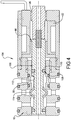
- a valve assembly 10 of the present disclosure includes a valve body 12 releasably connected to a solenoid can 14 using a threaded connection 16.
- a combined valve member/armature 18 is slidable in either of a valve closing direction "A" or a valve opening direction "B".
- Valve member/armature 18 is made as a homogenous or unitary combination of a valve member and an armature in a single element.
- valve member/armature 18 is made from a magnetically effected material such as steel, stainless steel, and the like.
- a coil 22 which includes wire in a plurality of windings is positioned within solenoid can 14.
- An adjustable pole piece 24 is positioned within coil 22 and connected to solenoid can 14 using a threaded connection 26. Adjustable pole piece 24 transfers a magnetic flux from an energized coil 22 to "pull" valve member/armature 18 from a valve closed to a valve open position.
- a biasing member 28, such as a coiled spring, within valve body 12 provides a biasing force to continuously bias the valve member/armature 18 toward the valve closing direction "A".
- a clearance gap 30 is provided between valve member/armature 18 and adjustable pole piece 24. Clearance gap 30 is created when biasing member 28 biases valve member/armature 18 in the valve closing direction "A".
- Clearance gap 30 is adjustable by rotating adjustable pole piece 24 using threaded connection 26 to axially displace adjustable pole piece 24 in either of the valve opening direction "A" or the valve closing direction "B".
- Clearance gap 30 defines a total valve member/armature 18 axial displacement between the valve closed (de-energized) and valve open (energized) positions plus overstroke.
- Clearance gap 30 also provides for adjustable axial displacement to compensate for wear of the valve member and/or valve seat.
- Clearance gap 30 can be adjusted throughout the life of the valve assembly to maintain the response time of the valve consistent. Decreasing clearance gap 30 decreases the time it takes for the valve to open, i.e., the valve opening time, and conversely, increasing clearance gap 30 increases a valve opening time. Clearance gap 30 is initially set to achieve optimal performance for the particular application.
- a first end of biasing member 28 is positioned within a member cavity 32 created at an end 34 of valve member/armature 18.
- a second end of biasing member 28 is retained within a pole piece cavity 36 created in a pole piece end 38 of adjustable pole piece 24.
- a solenoid bushing 40 is positioned between coil 22 and valve member/armature 18.
- Valve member/armature 18 is slidably disposed within a bushing bore 42 of solenoid bushing 40.
- a material for solenoid bushing 40 can be provided of a magnetic material such as steel or stainless steel and provides a sliding fit for valve member/armature 18.
- An electrical connector member 44 which can include one or more electrical wires is connected to and extends outwardly from coil 22. Electrical connector member 44 provides electrical power to energize coil 22 from a power source (not shown). Solenoid can 14, valve member/armature 18, coil 22, adjustable pole piece 24, solenoid bushing 40, and electrical connector member 44 together define a solenoid assembly.
- a pressure equalizing passage 46 extending throughout a length of valve member/armature 18 is oriented longitudinally and substantially co-axially with a corresponding passage 48 created through adjustable pole piece 24.
- Pressure equalizing passage 46 and passage 48 together provide a flow path for fluids such as air which is displaced as valve member/armature 18 slides within valve body 12.
- Pressure equalizing passage 46 can also vent fluid (e.g., air) which is present due to seal leakage.
- Valve body 12 includes an inlet port 50 which is in fluid communication with an inlet passage 52 which in turn connects to a pressurized chamber 54.
- Inlet passage 52 can be the same or a larger diameter as inlet port 50 or it can be smaller as shown. Inlet passage 52 can further be in the form of slots, or provided in other geometric shapes, including but not limited to rectangular, oval, and the like.
- Fluid in pressurized chamber 54 is provided from a source (not shown) of pressurized fluid such as air. The pressurized fluid is retained within pressurized chamber 54, when valve assembly 10 is in the valve closed position, by a seal 56 disposed in a piston 58 defining an end of valve member/armature 18. Piston 58 is slidably received within a cylinder bore 60 of valve body 12.
- valve element 62 An end of pressurized chamber 54 opposite from seal 56 is sealed when a valve element 62 is engaged with a first valve seat 64 of valve body 12.
- First valve seat 64 can define a sharp cornered, beveled, or rounded surface.
- Valve element 62 can be formed or machined from the same material as valve member/armature 18 or can be made of a resilient material such as rubber or synthetic rubber material connected such as by bonding, over-molding, loose seal, or other known processes to valve member/armature 18.
- Valve member/armature 18 can be made of any material able to be affected by the magnetic flux created through adjustable pole piece 24 when coil 22 is energized.
- Valve body 12 also includes a cylinder port 66 in fluid communication with a cylinder port passage 68.
- An exhaust port 70 is also provided in valve body 12 which is in fluid communication with an exhaust port passage 72.
- Cylinder port passage 68 is in fluid communication with a cylinder port chamber 74.
- cylinder port chamber 74 is created as a circumferential cavity in valve body 12.
- Exhaust port passage 72 is in fluid communication with an exhaust port chamber 76.
- exhaust port chamber 76 is created as a circumferential depression or cavity in valve member/armature 18, which is positioned proximate to exhaust port 70 in any operating position of valve member/armature 18.
- exhaust port cavity 78 is created as a circumferential slot provided in an adjustable retainer 80 which is positioned proximate to exhaust port passage 72.
- Adjustable retainer 80 is connected to valve body 12, after insertion of valve member/armature 18, using a threaded connection 82 to be axially adjustable parallel to valve longitudinal axis 20 by rotating adjustable retainer 80.
- a distance between adjustable retainer 80 and valve element 62 in the valve closed position can be increased or decreased and set at the optimal or desired position. This adjustment also determines a flow rate of the valve.
- a fluid seal is created between adjustable retainer 80 and an inner wall of valve body 12 using a first and a second O-ring 84, 86.
- First and second O-rings 84, 86 straddle exhaust port cavity 78, exhaust port passage 72, and exhaust port 70 and create a fluid seal which prevents fluid transfer through the exhaust port 70 or through the coil 22 section when valve member/armature is positioned in the valve open position.
- Valve body 12 further includes a plurality of body seals which in the example shown are provided as rubber or resilient material O-rings, but which can also be other types of seals adaptable to act about the perimeter of valve body 12. These seals include a first body seal 88, a second body seal 90, a third body seal 92, and a fourth body seal 94. First, second, third and fourth body seals 88, 90, 92, 94 are partially received in seal cavities or circumferential slots created in valve body 12 and are intended to sealingly mate with a valve body block such as the body block shown and described in reference to Figure 5 . In several embodiments, valve body 12 having first, second, third and fourth body seals 88 through 94 therefore defines a cartridge assembly which is slidably received in and is removable from the corresponding body block.
- valve closed position shown in Figure 1 is defined by engagement of a first side 95 of valve element 62 with first valve seat 64.
- the pressurized fluid provided through inlet port 50 is thereby retained within pressurized chamber 54.
- fluid pressure in cylinder port 66 is vented through exhaust port 70 by a path which includes cylinder port chamber 74, exhaust port chamber 76, exhaust port cavity 78, and exhaust port passage 72.
- coil 22 is de-energized which allows the biasing force provided by biasing member 28 to bias valve member/armature 18 toward the valve closing direction "A" which seats valve element 62 against first valve seat 64.
- clearance gap 30 provided between first end 34 of valve member/armature 18 and pole piece end 38 of adjustable pole piece 24 is adjustable and can be made smaller or larger by rotating adjustable pole piece 24 using threaded connection 26 to either increase or decrease clearance gap 30.
- Increasing or decreasing clearance gap 30 can increase or decrease, respectively, an opening and closing time of valve assembly 10.
- Clearance gap 30 can also be maintained during the life of valve assembly 10, for example to allow for compression set or wear of valve element 62.
- Axial adjustment of adjustable pole piece 24 operably controls a dimension "X" of clearance gap 30 created between adjustable pole piece 24 and the valve member/armature 18 with the valve member/armature 18 in the valve closed position.
- the clearance gap 30 also equates to a total throw distance of the valve member/armature 18, determined by a distance between the opposed valve seats, which effects the operating time of valve assembly 10.
- clearance gap 30 can be approximately 0.005 inches (0.13 mm).
- Access to adjustable pole piece 24 is provided through an open end of valve assembly 10, therefore adjustable pole piece 24 can be rotated to axially adjust its position to control the stroke or over-stroke of the solenoid assembly even when coil 22 of the valve is energized.
- Field adjustment of valve assembly 10 is therefore provided. Field adjustment also optimizes a valve shifting force, provides for wear compensation, and can be used to keep response times consistent throughout a valve lifespan.
- valve open position is defined when first side 95 of valve element 62 has moved away from first valve seat 64 and an opposed second side 97 of valve element 62 contacts second valve seat 96.
- the valve open position also occurs when clearance gap 30' is reduced but not permitted to reach a zero value, which would allow valve member/armature 18 to contact adjustable pole piece 24.
- valve member/armature 18 and adjustable pole piece 24 are undesirable because full sealing contact may not be present between valve member/armature 18 and adjustable pole piece 24, and because repeated contact can result in peening of the metal parts and increased noise. Eliminating contact therefore increases the operating life of valve assembly 10 by eliminating metal wear.
- Second valve seat 96 can define a sharp cornered, beveled, or rounded end of adjustable retainer 80 positioned proximate to valve element 62.
- First valve seat 64 can also define a sharp cornered, beveled, or rounded shape.
- adjustable retainer 80, and therefore a position of second valve seat 96 is longitudinally adjustable by rotation of adjustable retainer 80 using threaded connection 82.
- a total distance "Y" between first valve seat 64 and second valve seat 96 can be adjusted. This adjustment allows for compression set and wear of valve element 62 and adjustment of the valve opening and closing times.
- valve assembly 10 With coil 22 in the energized condition, valve assembly 10 will remain in the valve open position shown in Figure 2 .
- the fluid such as pressurized air provided through inlet port 50 into pressurized chamber 54 is discharged via cylinder port chamber 74, cylinder port passage 68, and cylinder port 66 to a fluid operated component or device (not shown).
- Flow through valve assembly 10 is therefore in an inlet flow direction "C" through inlet port 50 and in an outlet flow direction "D" from cylinder port 66.
- valve assembly 10 When valve element 62 is in contact with second valve seat 96 exhaust port 70 is isolated. In addition to the exit path provided by exhaust port 70, in the valve open position fluid in valve assembly 10 can also exit through a passage 98 defined between valve member/armature 18 and a bushing sleeve 100 of solenoid bushing 40. Fluid escaping through passage 98 will exit valve body 12 and valve assembly 10 through threaded connection 26 and therefore can contact coil 22. These paths are isolated in the valve closed position. Because it is anticipated that a pressure differential between fluid in exhaust port chamber 76 and exhaust port 70 is significantly less than a pressure differential between exhaust port chamber 76 via passage 98 and threaded connection 26, fluid will generally discharge via exhaust port 70 in the valve closed position. When coil 22 is de-energized, biasing member 28 will return valve member/armature 18 to the valve closed position shown in Figure 1 .
- valve element 62 wears over time with use, second surface area "F" is substantially unchanged, therefore retaining the pressure balanced condition on valve member/armature 18.
- a distance “Z” between a corner defined as second valve seat 96 of adjustable retainer 80 and a second face 103 of valve element 62 is shown. Distance “Z” is adjustable by axial displacement of adjustable retainer 80.
- the pressure balanced condition also occurs with the valve in the valve open position ( Figure 2 ) when fluid flow through cylinder port 66 stops, because the area of the opposed valve seat surfaces is substantially equal. These areas being pressure balanced also keep valve response times consistent with any variation of fluid pressure.
- valve assembly 10 when valve assembly 10 is in the valve open position, after the fluid volume has passed from inlet port 50 through cylinder port 66 which is used to operate the downstream equipment, the fluid pressure at inlet port 50 is substantially equal to the fluid pressure at cylinder port 66.
- a "pressure balanced" condition substantially exists in the valve open position due to the angular shape of the opposed sides of valve element 62.
- the fluid pressure acting against opposed sides of valve element 62 at the point of contact of valve element 62 and second valve seat 96 is substantially equal.
- coil 22 is subsequently de-energized, the biasing force of biasing element 28 needs to overcome only minimal fluid pressure to initiate movement of valve member/armature 18 from the valve closed position in the valve closing direction "A" back to the valve closed position shown in Figure 1 .
- valve assembly 104 is modified from valve assembly 10 to add a fluid seal.
- a valve member/armature 106 is modified from valve member/armature 18 by adding a seal member 108 such as an O-ring which is positioned within a seal groove 110 created in valve member/armature 106.
- Seal member 108 provides a fluid seal between valve member/armature 106 and a bore face 112 of adjustable retainer 80.
- the remaining components of valve assembly 104 are substantially unchanged from valve assembly 10.
- seal member 108 By adding seal member 108 to valve assembly 104, passage 98 is isolated under any operating condition of valve assembly 104.
- Use of seal member 108 can be selected depending upon the type of fluid to be controlled by valve assembly 104, for example in environments when the fluid is not easily filtered to remove contaminants such as dirt or moisture, or when the fluid is corrosive with respect to the materials of valve assembly 10 including coil 22.
- Use of seal member 108 prevents the damaging effects of the unfiltered or corrosive fluid from reaching the coil 22 area of valve assembly 104.
- seal member 108 isolates the flow path of passage 98 and threaded connection 26.
- seal member 108 also provides for the capability to use valve assembly 104 as a normally closed valve, a normally open valve, as a selector, or as a diverter assembly.
- the inlet port can also be relocated to any of the identified ports and valve assembly 104 can also be used with a vacuum system connected.
- Body block 116 is exemplary of any type of configuration for a receiving member of valve assembly 104.
- Body block 116 can include a plurality of fluid ports which define fluid communication paths for each of inlet port 50, cylinder port 66, and exhaust port 70. These fluid ports include a first fluid port 118 in fluid communication with each of the inlet ports 50, a second fluid port 120 in fluid communication with each of the cylinder ports 66, and a third fluid port 122 in fluid communication with each of the exhaust ports 70.
- First, second and third fluid ports 118, 120, 122 can be adapted to receive a connector 124 such as a threaded, welded, swaged, or other similar connector.
- a connector 124 such as a threaded, welded, swaged, or other similar connector.
- Each connector 124 is in turn connected to a fluid line 126 which can provide for example a source of pressurized fluid to inlet port 50, a flow path for fluid discharged from valve assembly 104 to a pressure operable device, or to vent the fluid to atmosphere from exhaust port 70.
- valve member/armature 106 is positioned in the valve open position which provides a path of fluid communication between inlet port 50 and cylinder port 66. In this condition, fluid at inlet port 50 will pass through valve assembly 104 and discharge via cylinder port 66.
- Body seals such as first, second, third, and fourth body seals 88 through 94 permit valve assembly 104 to be releasably inserted as a cartridge into body block 116. This permits valve assembly 104 to be removed for maintenance such as replacement of any of the various seals or adjustment of adjustable retainer 80.
- a two-way valve assembly 128 of the present disclosure includes a valve body 130 releasably connected to a solenoid can 132 using a threaded connection 134.
- a valve member/armature 136 is slidably disposed in valve body 130 for sliding motion on a valve longitudinal axis 138. Similar to valve member/armature 18, valve member/armature 136 is displaceable in each of the valve closing direction "A" and the valve opening direction "B".
- a coil 140 is disposed within solenoid can 132.
- An axially adjustable pole piece 142 similar to adjustable pole piece 24 is connected to solenoid can 132 using a threaded connection 144.
- a biasing member 146 such as a coil spring similar to biasing member 28 is positioned between a flanged portion 148 of valve member/armature 136 and a solenoid bushing 150. Biasing member 146 biases valve member/armature 136 in the valve closing direction "A" and therefore defines a clearance gap 151 between valve member/armature 136 and adjustable pole piece 142 when valve member/armature 136 is in the valve closed position. Clearance gap 151 is similar in function and adjustment to clearance gap 30 provided for valve assembly 10.
- Valve member/armature 136 is slidably disposed within a bushing sleeve 152 of solenoid bushing 150.
- a passage 154 is created between bushing sleeve 152 and valve member/armature 136 similar to passage 98.
- a pressure equalizing passage 156 is also provided in valve member/armature 136 similar in function to equalizing passage 46.
- Valve body 130 includes an inlet port 158 which is disposed at an angle ⁇ with respect to valve longitudinal axis 138. According to several embodiments angle ⁇ is approximately 45 degrees, but can vary at the discretion of the manufacturer. Inlet port 158 is in fluid communication with a pressurized chamber 160. Fluid in pressurized chamber 160 is retained by a seal 162 such as an O-ring circumferentially retained about a piston 164 of valve member/armature 136. Seal 162 contacts a cylinder bore 166 of valve body 130 to create a pressure fluid boundary at one end of pressurized chamber 160. An opposite end of pressured chamber 160 is created when a valve element 168 similar to valve element 62 contacts a valve seat 170 of valve body 130. The pressure balanced condition of valve assembly 10 is duplicated by the configuration of two-way valve assembly 128.
- Valve body 130 further includes a cylinder port 172 which is in fluid communication using a cylinder port passage 174 with a cylinder port chamber 176. Fluid pressure in inlet port 158 in normally isolated from cylinder port chamber 176 and therefore from cylinder port 172 in the valve closed position by contact of valve element 168 with valve seat 170.
- a seal member (not shown) such as seal member 108 shown and described in reference to Figure 4 can also be added to valve member/armature 136 to prevent pressurized fluid transfer through passage 154 and threaded connection 144. This seal member can be positioned in flanged portion 148 or between valve member/armature 136 and bushing sleeve 152.
- Valve body 130 differs from valve body 12 in its geometry proximate to the position of piston 164.
- a first body seal 178 such as an elastomeric material O-ring is positioned in a slot or groove created in an end face 180 of valve body 130. End face 180 is oriented substantially perpendicular to valve longitudinal axis 138.
- a second body seal 182 and a third body seal 184 are both disposed in corresponding slots created in a side face 186 of valve body 130.
- An angularly oriented face 188 is created between end face 180 and side face 186. Angled face 188 is substantially perpendicular to a central axis 189 of inlet port 158.
- two-way valve assembly 128 Operation of two-way valve assembly 128 is similar to each of valve assemblies 10 and 104.
- coil 140 When coil 140 is de-energized the biasing force of biasing member 146 urges valve member/armature 136 toward the valve closed position.
- coil 140 When coil 140 is energized, the magnetic flux induced through adjustable pole piece 142 pulls or draws valve member/armature 136 toward adjustable pole piece 142 until clearance gap 151 is reduced substantially to zero.
- An additional item such as a resilient material bushing or pad (not shown) can be positioned between valve member/armature 136 and adjustable pole piece 142, if desired, to reduce contact force and associated noise.
- valve element 168 withdraws from valve seat 170 allowing fluid in pressurized chamber 160 to discharge via cylinder port chamber 176, cylinder port passage 174 and through cylinder port 172.
- flanged portion 148 of valve member/armature 136 allows biasing member 146 to be positioned outside of valve member/armature 136, eliminating the need for member cavity 32 and pole piece cavity 36 of valve assembly 10.
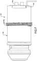
- a two-way valve assembly 190 is modified from two-way valve assembly 128 by the addition of a plurality of external body threads 192 which extend radially outward from a solenoid can 193. Threads 192 permit valve assembly 190 to be positively engaged with internal threads of a manifold such as a manifold block 196 which will be better described in reference to Figure 8 .
- an opposed pair of wrench flats 194 are provided with solenoid can 193.
- a fastener such as a wrench can engage wrench flats 194 to apply additional torque during assembly.
- a slotted end can be provided in an adjustable pole piece 195 for engagement by a different installation tool such as a screwdriver.
- a plurality of valve assemblies of the present disclosure can be commonly connected to a manifold as a space and costs saving measure, for operation of multiple components by the valve assemblies.
- a plurality of valve assemblies 190 are threadably connected into individual threaded receiving apertures of a manifold block 196.
- the valve assemblies 190 can be arranged in substantially parallel rows, indicated by first and second rows 198, 200.
- Groups of the valve assemblies 190 as shown by an exemplary group 202, can be commonly connected to one or more flow distribution devices 204.
- group 202 includes eight valve assemblies 190 which are commonly connected by internal flow passages (not shown) of manifold block 196 and a device mounting block 206 to flow distribution device 204.
- valve assemblies 190 can in turn be connected to each of flow distribution devices 204', 204", and 204"'.
- the quantity of valve assemblies and flow distribution devices is not limited by the exemplary configuration shown, and can vary at the discretion of the manufacturer. Grouping multiple ones of the valve assemblies also provides for ease in making the electrical connections to the valve assemblies, as a wiring harness (not shown) can be used to electrically energize multiple valve assemblies.
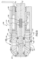
- Two-way valve assembly 208 includes a valve body 210 having a homogenous valve member/armature 212 slidably disposed therein.
- Valve body 210 is threadably connected to a solenoid can 214.
- Solenoid can 214 has an adjustable pole piece 216 threadably connected thereto, similar to adjustable pole piece 142.
- Valve member/armature 212 and adjustable pole piece 216 are modified to include a resilient member 218 such as a coiled spring disposed within a member cavity 220 and a pole piece cavity 222, respectively.
- Resilient member 218 biases valve member/armature 212 in a direction "H" tending to close valve assembly 208.
- Valve member/armature 212 is modified from valve member/armature 136 to include a radial flange portion 224 which includes an outer surface 226 slidably received within a receiving cavity 228 of a raised body portion 230.
- a seal 232 such as an O-ring positioned within a seal groove 234 of radial flange portion 224 provides a fluid boundary seal to prevent fluid from escaping past radial flange portion 224 and contacting a coil 236.
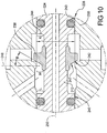
- Valve member/armature 212 further includes a valve element 238 integrally connected to valve member/armature 212 within a radial pocket 240 of valve member/armature 212, and therefore is modified from valve elements 62 and 168 as will be described in better detail in reference to Figure 10 .
- Valve element 238 contacts a valve seat 242 similar to valve seat 170.
- valve element 238 is adapted to be deflectable in a direction "G” to allow valve element 238 to deflect when disposed through receiving cavity 228 of raised body portion 230.
- both valve seat 242 and an internal surface 243 defined by receiving cavity 228 have substantially the same diameter "J".
- An end wall 244 of radial flange portion 224 therefore defines a surface area "K” which is substantially equal to a surface area "L” of a piston 245 (similar to piston 164) received in a piston cavity 246.
- Surface area “K” is also substantially equal to a surface area “M” of a portion of valve element 238 exposed to fluid pressure in the valve closed condition shown.
- Surface areas “L” and “M” are similar in function to first and second surface areas “E” and “F” shown in Figure 3 .
- Valve element 238 is modified from valve elements 62 and 168 by eliminating any portion of valve member/armature 212 extending radially outward which was partially received within valve elements 62 and 168.
- valve element 238 is received in radial pocket 240 which allows the portion of valve element 238 which freely radially extends away from valve member/armature 212 to deflect or bend.
- a surface 247 of valve element 238 is oriented at an angle ⁇ with respect to an axis 248 oriented substantially perpendicular to a longitudinal axis 250 of valve assembly 208.
- angle ⁇ can vary from approximately 20 degrees up to approximately 60 degrees. This range of angles is not limiting, however, and angle ⁇ can be larger or smaller at the discretion of the manufacturer.
- the coils 22, 140 for valve assemblies of the present disclosure are shown herein as substantially circular or tubular in shape. This shape is not limiting to the present disclosure. Additional coil shapes can also be used, such as rectangular, or non-round shapes such as oval, or multiple other geometric shapes. By varying the geometric shape of the coil, the coil wattage or valve operating speed can be varied by varying the design and quantity of windings defining an effective area of the coil. The remaining operating features of the valve assemblies of the present disclosure can be maintained with the various coil geometries described.
- the shape of the solenoid cans (14, 132, 193, 214) and the adjustable pole pieces (24, 142, 195, 216) can also be modified to correspond to the geometric shape of the coil. For example, a generally rectangular shaped solenoid can 193 can eliminate the need for the wrench flats 194 of valve assembly 190 shown in Figure 7 .
- valve body (12,130, 190, 210) is shown herein, the valve body can also have other configurations, such as but not limited to inline or manifold body styles.
- a valve stroke defined as the axial displacement of the valve member/armature (18, 106) from the valve closed to the valve open position is predetermined by the axial location of the adjustable retainer (80).
- a solenoid stroke generated by the solenoid assembly is predetermined by the axial location of the adjustable pole piece (24, 142, 195, 216).
- Valve assemblies of the present disclosure are also not limited to two-way and three-way designs, and can also be 4-way or greater valves.
- Pressure balanced solenoid operated valves of the present disclosure offer several advantages. By controlling the geometry at opposed ends of a pressurized chamber, a pressure balanced condition is created between a piston of a valve member/armature and a resilient valve element seated against a valve seat. The pressure balanced condition allows the valve member/armature to be retained in the valve closed position by the force of a biasing member only. To move the valve member/armature to a valve open position, the magnetic flux generated by a coil only has to overcome the biasing force of the biasing member. Due in part to the pressure balanced design of valve assemblies of the present disclosure, valve operating times less than 0.0004 seconds can be achieved, and valve operating frequencies greater than 2200 cycles per second can also be achieved.
- an axially adjustable retainer permits axial adjustment within a range of approximately 0.002 inches (0.05 mm) to 0.025 inches (0.635 mm).
Landscapes
- Engineering & Computer Science (AREA)
- General Engineering & Computer Science (AREA)
- Mechanical Engineering (AREA)
- Physics & Mathematics (AREA)
- Fluid Mechanics (AREA)
- Electromagnetism (AREA)
- Magnetically Actuated Valves (AREA)
- Multiple-Way Valves (AREA)
Claims (16)
- Elektromagnetisch betriebene Ventilanordnung (10), umfassend:eine Elektromagnetdose (14);einen Ventilkörper (12), der mit der Elektromagnetdose (14) verbunden ist;ein Polstück (24), das mit der Elektromagnetdose (14) verbunden ist, das zum Übertragen eines magnetischen Flusses betreibbar ist;ein homogenes Ventilelement/Anker (18) mit einem ersten Ende (34), das in der Nähe eines Polstückendes (38) des Polstücks (24) positioniert ist, und einem Kolben (58), der ein zweites Ende definiert, wobei das Ventilelement/Anker (18) aus einem homogenen Einzelelement aus einem magnetisch wirksamen Material besteht, wobei das Ventilelement/Anker (18) verschiebbar im Ventilkörper (12) angeordnet ist und von einer geschlossenen Ventilstellung zu einer offenen Ventilstellung in Gegenwart des magnetischen Flusses bewegt werden kann;ein Vorspannelement (28), das innerhalb des Ventilkörpers (12) positioniert ist, das eine Vorspannkraft bereitstellt, um das Ventilelement/den Anker (18) kontinuierlich in Richtung einer Ventilschließrichtung vorzuspannen, wobei ein erstes Ende des Vorspannelements (28) innerhalb eines Elementhohlraums (32) positioniert ist, der am ersten Ende des Ventilelements/Ankers (18) ausgebildet ist, und wobei ein zweites Ende des Vorspannelements (28) innerhalb eines Polstückhohlraums (36) gehalten wird, der im Polstückende (38) des Polstücks (24) ausgebildet ist; unddadurch gekennzeichnet, dass sie einen axial verstellbaren Halter (80) umfasst, der mit dem Ventilkörper (12) gewindemäßig verbunden und zur gleitenden Aufnahme des Ventilelements/Ankers (18) ausgelegt ist, wobei ein Abschnitt des Halters (80) einen zweiten Ventilsitz (96) definiert, wobei eine axiale Einstellung des Halters (80) zum axialen Verstellen des zweiten Ventilsitzes (96) betreibbar ist.
- Elektromagnetisch betriebene Ventilanordnung nach Anspruch 1, ferner umfassend:eine Einlassöffnung und einen Ventilsitz, die im Ventilkörper ausgebildet sind; undder Kolben des Ventilelements/Ankers, der einen ersten Oberflächenbereich in Fluidverbindung mit einem druckbeaufschlagten Fluid definiert, das der Einlassöffnung zugeführt wird.
- Elektromagnetisch betriebene Ventilanordnung nach Anspruch 2, ferner umfassend:ein Ventilelement mit einer ersten Seite, die einen zweiten Oberflächenbereich in Fluidverbindung mit dem druckbeaufschlagten Fluid in der geschlossenen Ventilstellung definiert, wobei das Ventilelement mit dem Ventilsitz in Kontakt steht;wobei der erste Oberflächenbereich im Wesentlichen gleich dem zweiten Oberflächenbereich ist, wobei das druckbeaufschlagte Fluid sowohl auf den ersten als auch auf den zweiten Oberflächenbereich wirkt, der einen druckausgeglichenen Zustand in der geschlossenen Ventilstellung definiert.
- Elektromagnetisch betriebene Ventilanordnung nach einem der Ansprüche 2-3, wobei der Ventilkörper ferner umfasst:eine Zylinderöffnung; undeinen Zylinderdurchgang, der eine Fluidverbindung zwischen der Einlassöffnung und der Zylinderöffnung in der offenen Ventilstellung bereitstellt.
- Elektromagnetisch betriebene Ventilanordnung nach Anspruch 4, ferner umfassend:eine Auslassöffnung, die in dem Ventilkörper ausgebildet ist; undeine Auslasskammer, die durch einen Hohlraum in dem Ventilelement/Anker definiert ist, wobei die Auslasskammer eine Fluidverbindung zwischen der Auslassöffnung und der Zylinderöffnung in der geschlossenen Ventilstellung bereitstellt.
- Elektromagnetisch betriebene Ventilanordnung nach Anspruch 5, ferner umfassend
erste und zweite O-Ringe, die zwischen dem Halter und dem Ventilkörper angeordnet sind, wobei die ersten und zweiten O-Ringe entgegengesetzt um die Auslassöffnung angeordnet sind und betreibbar sind, um eine Fluiddichtung zu definieren, die den Fluidtransfer durch die Auslassöffnung in der offenen Ventilstellung verhindert. - Elektromagnetisch betriebene Ventilanordnung nach Anspruch 1, ferner umfassend;
eine gegenüberliegende zweite Seite des Ventilelements, die einen dritten Oberflächenbereich in Fluidverbindung mit dem druckbeaufschlagten Fluid in der offenen Ventilstellung definiert, wobei die zweite Seite des Ventilelements in Kontakt mit dem zweiten Ventilsitz steht;
wobei der zweite Oberflächenbereich im Wesentlichen gleich dem dritten Oberflächenbereich ist, wobei das druckbeaufschlagte Fluid sowohl auf den zweiten als auch auf den dritten Oberflächenbereich wirkt, der einen druckausgeglichenen Zustand des offenen Ventils in der offenen Ventilstellung definiert. - Elektromagnetisch betriebene Ventilanordnung nach einem der Ansprüche 1-7, ferner umfassend:eine Gewindeverbindung, die betreibbar ist, um das Polstück verstellbar mit der Elektromagnetdose zu verbinden und eine axiale Verschiebung des Polstücks zu ermöglichen; undeine innerhalb des Elektromagneten angeordnete Spule kann unter Spannung betrieben werden, um den magnetischen Fluss durch das Polstück zu erzeugen, um das Ventilelement/den Anker in Richtung des Polstücks in eine offene Ventilrichtung zu ziehen; undeinen gesamten axialen Wurf des Ventilelements/Ankers, der durch einen einstellbaren Spielraum definiert ist, der zwischen dem Polstück und dem Ventilelement/Anker in der offenen Ventilstellung erzeugt wird, wobei das Polstück unter Verwendung der Gewindeverbindung axial einstellbar ist, um den Spielraum zu variieren.
- Elektromagnetisch betriebene Ventilanordnung nach einem der Ansprüche 1-8, ferner umfassend:
einen Druckausgleichskanal, der sich über eine gesamte Länge des Ventilelements/Ankers erstreckt; und einen Fluidkanal, der sich über das Polstück erstreckt und axial mit dem Druckausgleichskanal ausgerichtet ist. - Elektromagnetisch betriebene Ventilanordnung nach einem der Ansprüche 1-9,
wobei das Ventilelement des Ventilelements/Ankers ein elastisches Material umfasst. - Elektromagnetisch betriebene Ventilanordnung nach einem der Ansprüche 1-10,
wobei eine Fläche des Ventilelements einen Winkel in Bezug auf eine Achse definiert, die im Wesentlichen senkrecht zu einer Längsachse der Ventilanordnung ausgerichtet ist, der Winkel von etwa 20 Grad bis etwa 60 Grad reicht, und das Ventilelement in einem Schlitz angeordnet ist, der in Umfangsrichtung um das Ventilelement/den Anker herum ausgebildet ist. - Elektromagnetisch betriebene Ventilanordnung nach einem der Ansprüche 1, 5, 6 oder 7,
wobei das Ventilelement/der Anker ferner ein Ventilelement umfasst, das sich radial nach außen erstreckt, wobei das Ventilelement in der geschlossenen Ventilstellung in Kontakt mit dem ersten Ventilsitz und in der offenen Ventilstellung in Kontakt mit dem zweiten Ventilsitz steht. - Elektromagnetisch betriebene Ventilanordnung nach einem der Ansprüche 1-7, ferner umfassend:eine Elektromagnetbuchse, die geeignet ist, das Ventilelement/den Anker gleitend aufzunehmen, die einen Durchgang zwischen dem Ventilelement/dem Anker und der Elektromagnetbuchse definiert; undeine Gewindeverbindung, die betreibbar ist, um das Polstück verstellbar mit der Elektromagnetdose zu verbinden, wobei die Gewindeverbindung einen Fluidauslassweg definiert, auf dem das druckbeaufschlagte Fluid aus der Ventilanordnung in die Atmosphäre austritt;wobei das Dichtungselement betreibbar ist, um zu verhindern, dass das druckbeaufschlagte Fluid sowohl durch den Durchgang als auch durch den Fluidauslassweg strömt.
- Elektromagnetisch betriebene Ventilanordnung nach Anspruch 1 umfasst ferner:
eine Vielzahl von äußeren Körpergewinden, die sich radial nach außen von der Elektromagnetdose erstrecken, wobei die äußeren Körpergewinde es ermöglichen, dass die Ventilanordnung formschlüssig mit den inneren Gewinden eines Verteilers in Eingriff kommt. - Elektromagnetisch betriebene Ventilanordnung nach Anspruch 14, wobei der Elektromagnet mit einem gegenüberliegenden Paar Schlüsselflächen versehen ist, um das Drehen der Ventilanordnung während des Gewindeeingriffs der Vielzahl von äußeren Körpergewinden mit den inneren Gewinden eines Verteilers zu unterstützen.
- Elektromagnetisch betriebene Ventilanordnung nach Anspruch 14 umfasst ferner:
ein geschlitztes Ende, das in dem verstellbaren Polstück zum Eingriff mit einem Installationswerkzeug vorgesehen ist.
Priority Applications (1)
| Application Number | Priority Date | Filing Date | Title |
|---|---|---|---|
| PL08727076T PL2132471T3 (pl) | 2007-04-05 | 2008-03-21 | Odciążony zawór elektromagnetyczny |
Applications Claiming Priority (2)
| Application Number | Priority Date | Filing Date | Title |
|---|---|---|---|
| US11/784,106 US8151824B2 (en) | 2007-04-05 | 2007-04-05 | Balanced solenoid valve |
| PCT/US2008/003766 WO2008123926A2 (en) | 2007-04-05 | 2008-03-21 | Balanced solenoid valve |
Publications (3)
| Publication Number | Publication Date |
|---|---|
| EP2132471A2 EP2132471A2 (de) | 2009-12-16 |
| EP2132471A4 EP2132471A4 (de) | 2013-03-27 |
| EP2132471B1 true EP2132471B1 (de) | 2019-12-11 |
Family
ID=39825911
Family Applications (1)
| Application Number | Title | Priority Date | Filing Date |
|---|---|---|---|
| EP08727076.5A Active EP2132471B1 (de) | 2007-04-05 | 2008-03-21 | Ausgeglichenes magnetventil |
Country Status (15)
| Country | Link |
|---|---|
| US (1) | US8151824B2 (de) |
| EP (1) | EP2132471B1 (de) |
| JP (2) | JP2010523915A (de) |
| KR (1) | KR101213838B1 (de) |
| CN (1) | CN101688622B (de) |
| AU (1) | AU2008236867B2 (de) |
| BR (1) | BRPI0809508B1 (de) |
| CA (1) | CA2682226C (de) |
| ES (1) | ES2771723T3 (de) |
| MX (1) | MX2009010598A (de) |
| NZ (1) | NZ579868A (de) |
| PL (1) | PL2132471T3 (de) |
| PT (1) | PT2132471T (de) |
| WO (1) | WO2008123926A2 (de) |
| ZA (1) | ZA200906777B (de) |
Families Citing this family (40)
| Publication number | Priority date | Publication date | Assignee | Title |
|---|---|---|---|---|
| JP4807287B2 (ja) * | 2006-10-06 | 2011-11-02 | 株式会社デンソー | 電磁アクチュエータ |
| DE102010004975B4 (de) * | 2009-03-03 | 2014-02-06 | Stabilus Gmbh | Kolben-Zylindereinheit |
| US8453678B2 (en) * | 2009-04-01 | 2013-06-04 | Mac Valves, Inc. | Piloted poppet valve |
| US20100314568A1 (en) * | 2009-06-15 | 2010-12-16 | South Bend Controls, Inc. | Solenoid coil |
| US20110057132A1 (en) * | 2009-09-09 | 2011-03-10 | Gm Global Technology Operations, Inc. | Solenoid valve |
| DE102010009401A1 (de) * | 2010-02-26 | 2011-09-01 | Schaeffler Technologies Gmbh & Co. Kg | Proportionalventil, insbesondere für einen Nockenwellenversteller |
| JP5486987B2 (ja) * | 2010-03-31 | 2014-05-07 | Ckd株式会社 | バランスポペット式電磁弁 |
| KR101158423B1 (ko) * | 2010-05-26 | 2012-06-22 | 주식회사 케피코 | 차량의 자동변속기용 유압 솔레노이드 밸브 |
| US8939173B2 (en) * | 2010-07-14 | 2015-01-27 | Mac Valves, Inc. | Stepper motor operated balanced flow control valve |
| US9010373B2 (en) * | 2010-09-09 | 2015-04-21 | Mac Valves, Inc. | Pressure balanced valve with diaphragm valve member end seal |
| AU2010365794A1 (en) * | 2010-12-20 | 2013-07-04 | Mack Trucks, Inc. | Cartridge EGR valve assembly |
| CN102513963A (zh) * | 2011-12-31 | 2012-06-27 | 中国兵器工业集团第七○研究所 | 一种电控单体泵电磁控制阀装配工具 |
| US9103463B2 (en) * | 2012-02-14 | 2015-08-11 | Mac Valves, Inc. | Pressure balanced solenoid operated valve |
| KR101986573B1 (ko) * | 2012-03-15 | 2019-06-07 | 보르그워너 인코퍼레이티드 | 일방향 압력 구동식 피스톤 씰 |
| US9074699B2 (en) * | 2012-12-21 | 2015-07-07 | Mac Valves, Inc. | Multi-port normally open modular valve with thread-in seat |
| US8783653B2 (en) | 2012-12-21 | 2014-07-22 | Mac Valves, Inc. | Multi-port modular valve with snap-in seat |
| CN203868404U (zh) * | 2013-03-14 | 2014-10-08 | 伊顿公司 | 发动机气门机构油控制阀 |
| JP6751906B2 (ja) * | 2015-10-05 | 2020-09-09 | Smc株式会社 | 電磁弁及びマニホールド形電磁弁集合体 |
| DE102016006786A1 (de) | 2016-06-06 | 2017-12-07 | Focke & Co. (Gmbh & Co. Kg) | Modulares (Leim-)Ventil |
| DE102016006785A1 (de) | 2016-06-06 | 2017-12-07 | Focke & Co. (Gmbh & Co. Kg) | Ventil für fließfähige Medien, insbesondere Leimventil |
| CN106286053A (zh) * | 2016-09-09 | 2017-01-04 | 广东意希诺科技有限公司 | 非焊接式燃油吸入量控制阀 |
| CN106224621A (zh) * | 2016-09-09 | 2016-12-14 | 广东意希诺科技有限公司 | 分体式燃油计量阀 |
| US10578226B2 (en) * | 2016-12-22 | 2020-03-03 | Mac Valves, Inc. | Valve with two-piece adjustable can with integral pole piece |
| EP3409989B1 (de) * | 2017-05-31 | 2021-09-15 | Hamilton Sundstrand Corporation | Pneumatisches servoventil mit einstellbarer antriebseinheit |
| US10473229B2 (en) | 2017-09-25 | 2019-11-12 | Mac Valves, Inc. | Diaphragm valve |
| CN109780224A (zh) * | 2017-11-13 | 2019-05-21 | 艾默生环境优化技术(苏州)有限公司 | 电子膨胀阀 |
| DE102017222453A1 (de) * | 2017-12-12 | 2019-06-13 | Festo Ag & Co. Kg | Ventil |
| DE102019103207A1 (de) | 2018-02-27 | 2019-08-29 | Borgwarner Inc. | Elektromagnetbetätigtes ventil und hydrauliksteuermodul, das dieses umfasst |
| CN108916419B (zh) * | 2018-06-29 | 2020-07-14 | 北京精密机电控制设备研究所 | 一种高压多功能两位三通电磁阀 |
| US10598298B2 (en) * | 2018-08-27 | 2020-03-24 | Borg Warner Inc. | Control valve and hydraulic control module including the same |
| CN209164045U (zh) * | 2018-11-19 | 2019-07-26 | 浙江锐韦机电科技有限公司 | 泵阀一体机构 |
| US11035482B2 (en) * | 2019-01-31 | 2021-06-15 | Scott Dale Follett | Pressure relief valve |
| GB2582959A (en) * | 2019-04-11 | 2020-10-14 | Penny & Giles Controls Ltd | Solenoid Valve |
| CN210372066U (zh) * | 2019-06-14 | 2020-04-21 | 浙江盾安禾田金属有限公司 | 电子膨胀阀 |
| US11779872B2 (en) * | 2019-09-18 | 2023-10-10 | Mac Valves, Inc. | Pulse valve |
| CN113090769B (zh) * | 2019-12-23 | 2025-02-25 | 上海气立可气动设备有限公司 | 平衡型高速电磁阀 |
| CA3197002A1 (en) * | 2020-10-30 | 2022-05-05 | Rajesh Shah | A pneumatic valve with flexi-seals |
| EP4264094A1 (de) * | 2020-12-18 | 2023-10-25 | ECO Holding 1 GmbH | Proportionalventilanordnung für kältemittel |
| CN113074156B (zh) * | 2021-04-15 | 2023-04-28 | 华北电力大学 | 一种加装接触密封的液压换向阀 |
| CN115479147B (zh) * | 2021-09-26 | 2024-04-05 | 广东骏驰科技股份有限公司 | 一种油路控制阀 |
Citations (1)
| Publication number | Priority date | Publication date | Assignee | Title |
|---|---|---|---|---|
| US4979542A (en) * | 1988-04-27 | 1990-12-25 | Siemens Automotive L.P. | Pulse modulated hydraulic valve |
Family Cites Families (63)
| Publication number | Priority date | Publication date | Assignee | Title |
|---|---|---|---|---|
| US1822668A (en) | 1927-02-23 | 1931-09-08 | O F Jordan Co | Electromagnetic valve |
| US2826215A (en) | 1954-04-21 | 1958-03-11 | Alco Valve Co | Balanced pressure solenoid valve |
| US2987293A (en) | 1958-01-06 | 1961-06-06 | Bendix Corp | Valve |
| US3368791A (en) | 1964-07-14 | 1968-02-13 | Marotta Valve Corp | Valve with magnetic actuator |
| US3379214A (en) | 1965-01-15 | 1968-04-23 | Skinner Prec Ind Inc | Permanent magnet valve assembly |
| US3429552A (en) | 1965-07-08 | 1969-02-25 | Dole Valve Co | Adjustable rate valve assembly |
| US3737141A (en) | 1972-04-13 | 1973-06-05 | Control Concepts | Normally closed solenoid operated valve |
| CA1021225A (en) | 1974-06-28 | 1977-11-22 | General Signal Corporation | Quick-acting valve assembly |
| US3985333A (en) | 1975-09-02 | 1976-10-12 | Spraying Systems Co. | Solenoid valve |
| US4050477A (en) * | 1975-10-31 | 1977-09-27 | International Telephone And Telegraph Corporation | Valve |
| DE3002361A1 (de) * | 1979-01-25 | 1980-07-31 | Lucas Industries Ltd | Steuerventil |
| JPS5691965U (de) * | 1979-12-19 | 1981-07-22 | ||
| JPS56111383U (de) * | 1980-01-28 | 1981-08-28 | ||
| JPS56111384U (de) * | 1980-01-28 | 1981-08-28 | ||
| GB2087519B (en) | 1980-11-01 | 1984-05-16 | Lucas Industries Ltd | Solenoid-operated valve means for hydraulic systems |
| GB2103337B (en) * | 1981-07-30 | 1985-04-11 | Mac Valves Inc | Three-way normally closed pilot valve |
| US4624285A (en) * | 1983-08-16 | 1986-11-25 | United Technologies Automotive, Inc. | Control valve assembly |
| US4632358A (en) | 1984-07-17 | 1986-12-30 | Eaton Corporation | Automotive air conditioning system including electrically operated expansion valve |
| JPS6124580U (ja) * | 1984-07-20 | 1986-02-13 | エスエムシ−株式会社 | 方向切換弁 |
| US4598736A (en) | 1984-12-03 | 1986-07-08 | Chorkey William J | Solenoid operated valve with balancing means |
| JPH0624615Y2 (ja) * | 1985-11-14 | 1994-06-29 | エスエムシー株式会社 | ポペット式方向切換弁 |
| JPH0524871Y2 (de) * | 1986-01-13 | 1993-06-23 | ||
| JPS6441780U (de) | 1987-09-07 | 1989-03-13 | ||
| DE3732553A1 (de) | 1987-09-26 | 1989-04-13 | Bosch Gmbh Robert | Magnetventil |
| JPH01148181U (de) | 1988-03-31 | 1989-10-13 | ||
| US4821774A (en) * | 1988-04-04 | 1989-04-18 | Chorkey William J | Solenoid operated valve with balancing means |
| US4830333A (en) | 1988-09-02 | 1989-05-16 | General Motors Corporation | Solenoid valve |
| US4858956A (en) | 1988-09-22 | 1989-08-22 | Siemens-Bendix Automotive Electronics L.P. | High pressure, fast response, pressure balanced, solenoid control valve |
| JPH0251778U (de) | 1988-10-05 | 1990-04-12 | ||
| US4880033A (en) * | 1988-12-12 | 1989-11-14 | Mac Valves, Inc. | Poppet valve |
| US4915134A (en) * | 1989-07-27 | 1990-04-10 | Humphrey Products Company | Three-way poppet valve with hollow stem |
| JP2517263Y2 (ja) * | 1990-08-31 | 1996-11-20 | シャープ株式会社 | 電話機 |
| US5092365A (en) * | 1991-03-18 | 1992-03-03 | Mac Valves, Inc. | Valve with adjustable valve seat |
| US5217047A (en) | 1991-05-30 | 1993-06-08 | Coltec Industries Inc. | Solenoid operated pressure regulating valve |
| US5251659A (en) | 1991-07-22 | 1993-10-12 | Sturman Oded E | High speed miniature solenoid |
| JPH066852U (ja) * | 1992-06-30 | 1994-01-28 | エヌオーケー株式会社 | ソレノイド |
| US5211198A (en) * | 1992-10-15 | 1993-05-18 | Humphrey Products Company | Poppet construction for valve |
| EP0621426B1 (de) | 1993-03-19 | 1998-09-16 | Cummins Engine Company, Inc. | Druckausgeglichenes Dreiwegemagnetventil |
| DE69400242T2 (de) | 1993-03-31 | 1996-10-10 | Cummins Engine Co Inc | Kompaktes Dreiwegeventil mit einem Dorn in einer Hülse |
| JPH07174106A (ja) | 1993-12-21 | 1995-07-11 | Zexel Corp | 電磁比例圧力制御弁 |
| US5497975A (en) | 1994-04-29 | 1996-03-12 | Hr Textron Inc. | Solenoid pneumatic valve |
| JP3451283B2 (ja) * | 1994-06-17 | 2003-09-29 | Smc株式会社 | バランス形直動電磁弁 |
| DE4426796A1 (de) | 1994-07-28 | 1996-02-01 | Bosch Gmbh Robert | Elektromagnetventil, insbesondere für schlupfgeregelte hydraulische Bremsanlagen in Kraftfahrzeugen |
| US5593132A (en) * | 1995-06-30 | 1997-01-14 | Siemens Electric Limited | Electromagnetic actuator arrangement for engine control valve |
| US5855228A (en) * | 1995-09-05 | 1999-01-05 | Perach; Asi | Control valve assembly |
| JPH09100941A (ja) * | 1995-10-06 | 1997-04-15 | Fujikin:Kk | 流動制御機器 |
| US5641148A (en) | 1996-01-11 | 1997-06-24 | Sturman Industries | Solenoid operated pressure balanced valve |
| WO1997044580A1 (en) | 1996-05-20 | 1997-11-27 | Borg-Warner Automotive, Inc. | Automotive fluid control system with pressure balanced solenoid valve |
| US5836230A (en) | 1996-08-27 | 1998-11-17 | Oded E. Sturman | High speed 2-way control valve |
| US5878647A (en) * | 1997-08-11 | 1999-03-09 | Husco International Inc. | Pilot solenoid control valve and hydraulic control system using same |
| US6116276A (en) | 1998-02-09 | 2000-09-12 | Sturman Bg, Llc | Balance latching fluid valve |
| US6029703A (en) | 1998-12-18 | 2000-02-29 | Borg-Warner Automotive, Inc. | Pressure solenoid control valve with flux shunt |
| DE19934846A1 (de) * | 1999-07-24 | 2001-01-25 | Hydraulik Ring Gmbh | Elektromagnet und hydraulisches Ventil mit einem Elektromagneten |
| US6405757B1 (en) | 2000-08-01 | 2002-06-18 | Humphrey Products Company | Low power solenoid valve assembly |
| DE10146422A1 (de) | 2000-10-02 | 2002-05-08 | Caterpillar Inc | Zugelektromagnet mit hoher Kraft |
| US20020162592A1 (en) | 2001-05-01 | 2002-11-07 | Bowden Charles J. | Solenoid operated, three way, normally closed, high flow, pressure compensated proportional pilot valve |
| US6488050B1 (en) * | 2001-07-10 | 2002-12-03 | Humphrey Products Company | Pneumatic valve assembly |
| US20030042450A1 (en) | 2001-08-31 | 2003-03-06 | Bircann Raul A. | Force-balanced gas control valve |
| US6691980B2 (en) | 2002-07-05 | 2004-02-17 | Tescom Corporation | Balanced valve with actuator |
| US6974117B2 (en) * | 2003-08-27 | 2005-12-13 | South Bend Controls, Inc. | Proportional valve actuating apparatus |
| JP2006046414A (ja) * | 2004-08-02 | 2006-02-16 | Smc Corp | 3ポート電磁弁 |
| US20060027269A1 (en) * | 2004-08-06 | 2006-02-09 | Neff Robert H | Rapid response solenoid for electromagnetic operated valve |
| US7210501B2 (en) * | 2004-09-29 | 2007-05-01 | Mac Valves, Inc. | Directly operated pneumatic valve having a differential assist return |
-
2007
- 2007-04-05 US US11/784,106 patent/US8151824B2/en active Active
-
2008
- 2008-03-21 NZ NZ57986808A patent/NZ579868A/xx unknown
- 2008-03-21 WO PCT/US2008/003766 patent/WO2008123926A2/en not_active Ceased
- 2008-03-21 JP JP2010502084A patent/JP2010523915A/ja active Pending
- 2008-03-21 AU AU2008236867A patent/AU2008236867B2/en active Active
- 2008-03-21 MX MX2009010598A patent/MX2009010598A/es active IP Right Grant
- 2008-03-21 PT PT87270765T patent/PT2132471T/pt unknown
- 2008-03-21 BR BRPI0809508A patent/BRPI0809508B1/pt active IP Right Grant
- 2008-03-21 EP EP08727076.5A patent/EP2132471B1/de active Active
- 2008-03-21 CN CN2008800110589A patent/CN101688622B/zh active Active
- 2008-03-21 ES ES08727076T patent/ES2771723T3/es active Active
- 2008-03-21 CA CA 2682226 patent/CA2682226C/en active Active
- 2008-03-21 KR KR1020097021980A patent/KR101213838B1/ko active Active
- 2008-03-21 PL PL08727076T patent/PL2132471T3/pl unknown
-
2009
- 2009-09-29 ZA ZA2009/06777A patent/ZA200906777B/en unknown
-
2013
- 2013-02-20 JP JP2013031491A patent/JP5632933B2/ja active Active
Patent Citations (1)
| Publication number | Priority date | Publication date | Assignee | Title |
|---|---|---|---|---|
| US4979542A (en) * | 1988-04-27 | 1990-12-25 | Siemens Automotive L.P. | Pulse modulated hydraulic valve |
Also Published As
| Publication number | Publication date |
|---|---|
| AU2008236867B2 (en) | 2012-10-11 |
| JP2013092258A (ja) | 2013-05-16 |
| EP2132471A4 (de) | 2013-03-27 |
| PL2132471T3 (pl) | 2020-11-02 |
| JP5632933B2 (ja) | 2014-11-26 |
| NZ579868A (en) | 2012-10-26 |
| PT2132471T (pt) | 2020-03-17 |
| US20080245427A1 (en) | 2008-10-09 |
| BRPI0809508B1 (pt) | 2020-04-07 |
| HK1140248A1 (en) | 2010-10-08 |
| JP2010523915A (ja) | 2010-07-15 |
| KR20100015766A (ko) | 2010-02-12 |
| ES2771723T3 (es) | 2020-07-06 |
| CA2682226A1 (en) | 2008-10-16 |
| MX2009010598A (es) | 2009-11-12 |
| CA2682226C (en) | 2012-08-28 |
| WO2008123926A3 (en) | 2008-12-18 |
| AU2008236867A1 (en) | 2008-10-16 |
| KR101213838B1 (ko) | 2012-12-18 |
| ZA200906777B (en) | 2010-12-29 |
| BRPI0809508A2 (pt) | 2014-10-14 |
| CN101688622A (zh) | 2010-03-31 |
| CN101688622B (zh) | 2013-05-22 |
| US8151824B2 (en) | 2012-04-10 |
| EP2132471A2 (de) | 2009-12-16 |
| WO2008123926A2 (en) | 2008-10-16 |
Similar Documents
| Publication | Publication Date | Title |
|---|---|---|
| EP2132471B1 (de) | Ausgeglichenes magnetventil | |
| EP2136117B1 (de) | Ausgeglichenes Magnetventil | |
| KR101858449B1 (ko) | 일정한 브리드 포트를 가지는 솔레노이드 동작형 밸브 | |
| TWI596291B (zh) | 具有扣合式座的多埠模組閥 | |
| HK1140248B (en) | Balanced solenoid valve | |
| HK1152738B (en) | Balanced solenoid valve | |
| HK1196658A (en) | Solenoid operated valve with constant bleed port | |
| HK1196658B (en) | Solenoid operated valve with constant bleed port |
Legal Events
| Date | Code | Title | Description |
|---|---|---|---|
| PUAI | Public reference made under article 153(3) epc to a published international application that has entered the european phase |
Free format text: ORIGINAL CODE: 0009012 |
|
| 17P | Request for examination filed |
Effective date: 20091001 |
|
| AK | Designated contracting states |
Kind code of ref document: A2 Designated state(s): AT BE BG CH CY CZ DE DK EE ES FI FR GB GR HR HU IE IS IT LI LT LU LV MC MT NL NO PL PT RO SE SI SK TR |
|
| DAX | Request for extension of the european patent (deleted) | ||
| A4 | Supplementary search report drawn up and despatched |
Effective date: 20130221 |
|
| RIC1 | Information provided on ipc code assigned before grant |
Ipc: F15B 13/044 20060101ALI20130215BHEP Ipc: F16K 31/06 20060101AFI20130215BHEP |
|
| STAA | Information on the status of an ep patent application or granted ep patent |
Free format text: STATUS: EXAMINATION IS IN PROGRESS |
|
| 17Q | First examination report despatched |
Effective date: 20180711 |
|
| GRAP | Despatch of communication of intention to grant a patent |
Free format text: ORIGINAL CODE: EPIDOSNIGR1 |
|
| STAA | Information on the status of an ep patent application or granted ep patent |
Free format text: STATUS: GRANT OF PATENT IS INTENDED |
|
| INTG | Intention to grant announced |
Effective date: 20190628 |
|
| GRAS | Grant fee paid |
Free format text: ORIGINAL CODE: EPIDOSNIGR3 |
|
| GRAA | (expected) grant |
Free format text: ORIGINAL CODE: 0009210 |
|
| STAA | Information on the status of an ep patent application or granted ep patent |
Free format text: STATUS: THE PATENT HAS BEEN GRANTED |
|
| AK | Designated contracting states |
Kind code of ref document: B1 Designated state(s): AT BE BG CH CY CZ DE DK EE ES FI FR GB GR HR HU IE IS IT LI LT LU LV MC MT NL NO PL PT RO SE SI SK TR |
|
| REG | Reference to a national code |
Ref country code: GB Ref legal event code: FG4D |
|
| REG | Reference to a national code |
Ref country code: CH Ref legal event code: EP Ref country code: CH Ref legal event code: NV Representative=s name: RIEDERER HASLER AND PARTNER PATENTANWAELTE AG, LI |
|
| REG | Reference to a national code |
Ref country code: AT Ref legal event code: REF Ref document number: 1212531 Country of ref document: AT Kind code of ref document: T Effective date: 20191215 |
|
| REG | Reference to a national code |
Ref country code: DE Ref legal event code: R096 Ref document number: 602008061805 Country of ref document: DE |
|
| REG | Reference to a national code |
Ref country code: IE Ref legal event code: FG4D |
|
| REG | Reference to a national code |
Ref country code: NL Ref legal event code: FP |
|
| REG | Reference to a national code |
Ref country code: PT Ref legal event code: SC4A Ref document number: 2132471 Country of ref document: PT Date of ref document: 20200317 Kind code of ref document: T Free format text: AVAILABILITY OF NATIONAL TRANSLATION Effective date: 20200305 |
|
| REG | Reference to a national code |
Ref country code: SE Ref legal event code: TRGR |
|
| REG | Reference to a national code |
Ref country code: GR Ref legal event code: EP Ref document number: 20200400187 Country of ref document: GR Effective date: 20200415 |
|
| REG | Reference to a national code |
Ref country code: LT Ref legal event code: MG4D |
|
| PG25 | Lapsed in a contracting state [announced via postgrant information from national office to epo] |
Ref country code: BG Free format text: LAPSE BECAUSE OF FAILURE TO SUBMIT A TRANSLATION OF THE DESCRIPTION OR TO PAY THE FEE WITHIN THE PRESCRIBED TIME-LIMIT Effective date: 20200311 Ref country code: FI Free format text: LAPSE BECAUSE OF FAILURE TO SUBMIT A TRANSLATION OF THE DESCRIPTION OR TO PAY THE FEE WITHIN THE PRESCRIBED TIME-LIMIT Effective date: 20191211 Ref country code: NO Free format text: LAPSE BECAUSE OF FAILURE TO SUBMIT A TRANSLATION OF THE DESCRIPTION OR TO PAY THE FEE WITHIN THE PRESCRIBED TIME-LIMIT Effective date: 20200311 Ref country code: LT Free format text: LAPSE BECAUSE OF FAILURE TO SUBMIT A TRANSLATION OF THE DESCRIPTION OR TO PAY THE FEE WITHIN THE PRESCRIBED TIME-LIMIT Effective date: 20191211 Ref country code: LV Free format text: LAPSE BECAUSE OF FAILURE TO SUBMIT A TRANSLATION OF THE DESCRIPTION OR TO PAY THE FEE WITHIN THE PRESCRIBED TIME-LIMIT Effective date: 20191211 |
|
| PG25 | Lapsed in a contracting state [announced via postgrant information from national office to epo] |
Ref country code: HR Free format text: LAPSE BECAUSE OF FAILURE TO SUBMIT A TRANSLATION OF THE DESCRIPTION OR TO PAY THE FEE WITHIN THE PRESCRIBED TIME-LIMIT Effective date: 20191211 |
|
| REG | Reference to a national code |
Ref country code: ES Ref legal event code: FG2A Ref document number: 2771723 Country of ref document: ES Kind code of ref document: T3 Effective date: 20200706 |
|
| PG25 | Lapsed in a contracting state [announced via postgrant information from national office to epo] |
Ref country code: EE Free format text: LAPSE BECAUSE OF FAILURE TO SUBMIT A TRANSLATION OF THE DESCRIPTION OR TO PAY THE FEE WITHIN THE PRESCRIBED TIME-LIMIT Effective date: 20191211 Ref country code: RO Free format text: LAPSE BECAUSE OF FAILURE TO SUBMIT A TRANSLATION OF THE DESCRIPTION OR TO PAY THE FEE WITHIN THE PRESCRIBED TIME-LIMIT Effective date: 20191211 |
|
| PG25 | Lapsed in a contracting state [announced via postgrant information from national office to epo] |
Ref country code: SK Free format text: LAPSE BECAUSE OF FAILURE TO SUBMIT A TRANSLATION OF THE DESCRIPTION OR TO PAY THE FEE WITHIN THE PRESCRIBED TIME-LIMIT Effective date: 20191211 Ref country code: IS Free format text: LAPSE BECAUSE OF FAILURE TO SUBMIT A TRANSLATION OF THE DESCRIPTION OR TO PAY THE FEE WITHIN THE PRESCRIBED TIME-LIMIT Effective date: 20200411 |
|
| REG | Reference to a national code |
Ref country code: DE Ref legal event code: R097 Ref document number: 602008061805 Country of ref document: DE |
|
| PLBE | No opposition filed within time limit |
Free format text: ORIGINAL CODE: 0009261 |
|
| STAA | Information on the status of an ep patent application or granted ep patent |
Free format text: STATUS: NO OPPOSITION FILED WITHIN TIME LIMIT |
|
| PG25 | Lapsed in a contracting state [announced via postgrant information from national office to epo] |
Ref country code: MC Free format text: LAPSE BECAUSE OF FAILURE TO SUBMIT A TRANSLATION OF THE DESCRIPTION OR TO PAY THE FEE WITHIN THE PRESCRIBED TIME-LIMIT Effective date: 20191211 Ref country code: DK Free format text: LAPSE BECAUSE OF FAILURE TO SUBMIT A TRANSLATION OF THE DESCRIPTION OR TO PAY THE FEE WITHIN THE PRESCRIBED TIME-LIMIT Effective date: 20191211 |
|
| 26N | No opposition filed |
Effective date: 20200914 |
|
| PG25 | Lapsed in a contracting state [announced via postgrant information from national office to epo] |
Ref country code: SI Free format text: LAPSE BECAUSE OF FAILURE TO SUBMIT A TRANSLATION OF THE DESCRIPTION OR TO PAY THE FEE WITHIN THE PRESCRIBED TIME-LIMIT Effective date: 20191211 |
|
| PG25 | Lapsed in a contracting state [announced via postgrant information from national office to epo] |
Ref country code: LU Free format text: LAPSE BECAUSE OF NON-PAYMENT OF DUE FEES Effective date: 20200321 |
|
| REG | Reference to a national code |
Ref country code: AT Ref legal event code: UEP Ref document number: 1212531 Country of ref document: AT Kind code of ref document: T Effective date: 20191211 |
|
| PG25 | Lapsed in a contracting state [announced via postgrant information from national office to epo] |
Ref country code: TR Free format text: LAPSE BECAUSE OF FAILURE TO SUBMIT A TRANSLATION OF THE DESCRIPTION OR TO PAY THE FEE WITHIN THE PRESCRIBED TIME-LIMIT Effective date: 20191211 Ref country code: MT Free format text: LAPSE BECAUSE OF FAILURE TO SUBMIT A TRANSLATION OF THE DESCRIPTION OR TO PAY THE FEE WITHIN THE PRESCRIBED TIME-LIMIT Effective date: 20191211 Ref country code: CY Free format text: LAPSE BECAUSE OF FAILURE TO SUBMIT A TRANSLATION OF THE DESCRIPTION OR TO PAY THE FEE WITHIN THE PRESCRIBED TIME-LIMIT Effective date: 20191211 |
|
| PGFP | Annual fee paid to national office [announced via postgrant information from national office to epo] |
Ref country code: SE Payment date: 20250312 Year of fee payment: 18 |
|
| PGFP | Annual fee paid to national office [announced via postgrant information from national office to epo] |
Ref country code: PT Payment date: 20250310 Year of fee payment: 18 Ref country code: DE Payment date: 20250327 Year of fee payment: 18 |
|
| PGFP | Annual fee paid to national office [announced via postgrant information from national office to epo] |
Ref country code: NL Payment date: 20250327 Year of fee payment: 18 |
|
| PGFP | Annual fee paid to national office [announced via postgrant information from national office to epo] |
Ref country code: IE Payment date: 20250327 Year of fee payment: 18 |
|
| PGFP | Annual fee paid to national office [announced via postgrant information from national office to epo] |
Ref country code: GR Payment date: 20250331 Year of fee payment: 18 Ref country code: BE Payment date: 20250327 Year of fee payment: 18 Ref country code: AT Payment date: 20250305 Year of fee payment: 18 |
|
| PGFP | Annual fee paid to national office [announced via postgrant information from national office to epo] |
Ref country code: FR Payment date: 20250325 Year of fee payment: 18 Ref country code: PL Payment date: 20250305 Year of fee payment: 18 Ref country code: CZ Payment date: 20250307 Year of fee payment: 18 |
|
| PGFP | Annual fee paid to national office [announced via postgrant information from national office to epo] |
Ref country code: IT Payment date: 20250319 Year of fee payment: 18 Ref country code: GB Payment date: 20250327 Year of fee payment: 18 |
|
| PGFP | Annual fee paid to national office [announced via postgrant information from national office to epo] |
Ref country code: ES Payment date: 20250401 Year of fee payment: 18 |
|
| PGFP | Annual fee paid to national office [announced via postgrant information from national office to epo] |
Ref country code: CH Payment date: 20250401 Year of fee payment: 18 |