EP2132468B1 - Valve - Google Patents
Valve Download PDFInfo
- Publication number
- EP2132468B1 EP2132468B1 EP20080733725 EP08733725A EP2132468B1 EP 2132468 B1 EP2132468 B1 EP 2132468B1 EP 20080733725 EP20080733725 EP 20080733725 EP 08733725 A EP08733725 A EP 08733725A EP 2132468 B1 EP2132468 B1 EP 2132468B1
- Authority
- EP
- European Patent Office
- Prior art keywords
- plug
- valve
- flow
- opening
- subchamber
- Prior art date
- Legal status (The legal status is an assumption and is not a legal conclusion. Google has not performed a legal analysis and makes no representation as to the accuracy of the status listed.)
- Not-in-force
Links
- 239000012530 fluid Substances 0.000 claims description 22
- 238000004891 communication Methods 0.000 claims description 8
- 238000012886 linear function Methods 0.000 claims description 2
- XLYOFNOQVPJJNP-UHFFFAOYSA-N water Substances O XLYOFNOQVPJJNP-UHFFFAOYSA-N 0.000 claims description 2
- 239000002826 coolant Substances 0.000 description 22
- 230000004048 modification Effects 0.000 description 8
- 238000012986 modification Methods 0.000 description 8
- 239000000463 material Substances 0.000 description 7
- 239000000446 fuel Substances 0.000 description 6
- 229910052782 aluminium Inorganic materials 0.000 description 5
- XAGFODPZIPBFFR-UHFFFAOYSA-N aluminium Chemical compound [Al] XAGFODPZIPBFFR-UHFFFAOYSA-N 0.000 description 5
- 238000002485 combustion reaction Methods 0.000 description 4
- 238000010276 construction Methods 0.000 description 4
- 238000007789 sealing Methods 0.000 description 4
- 241000237503 Pectinidae Species 0.000 description 2
- 230000008901 benefit Effects 0.000 description 2
- 238000005266 casting Methods 0.000 description 2
- 238000001816 cooling Methods 0.000 description 2
- 238000004519 manufacturing process Methods 0.000 description 2
- 230000010355 oscillation Effects 0.000 description 2
- 230000002093 peripheral effect Effects 0.000 description 2
- 235000020637 scallop Nutrition 0.000 description 2
- 229910001220 stainless steel Inorganic materials 0.000 description 2
- 239000010935 stainless steel Substances 0.000 description 2
- 241000937378 Everettia interior Species 0.000 description 1
- 229910000831 Steel Inorganic materials 0.000 description 1
- 230000004308 accommodation Effects 0.000 description 1
- 230000008859 change Effects 0.000 description 1
- 230000003750 conditioning effect Effects 0.000 description 1
- 238000009826 distribution Methods 0.000 description 1
- 238000010438 heat treatment Methods 0.000 description 1
- 230000001788 irregular Effects 0.000 description 1
- 238000000034 method Methods 0.000 description 1
- 239000002991 molded plastic Substances 0.000 description 1
- 238000013021 overheating Methods 0.000 description 1
- 239000004033 plastic Substances 0.000 description 1
- 229920003023 plastic Polymers 0.000 description 1
- 230000004044 response Effects 0.000 description 1
- 230000006903 response to temperature Effects 0.000 description 1
- 230000004043 responsiveness Effects 0.000 description 1
- 230000003068 static effect Effects 0.000 description 1
- 239000010959 steel Substances 0.000 description 1
- 238000006467 substitution reaction Methods 0.000 description 1
Images


Classifications
-
- F—MECHANICAL ENGINEERING; LIGHTING; HEATING; WEAPONS; BLASTING
- F01—MACHINES OR ENGINES IN GENERAL; ENGINE PLANTS IN GENERAL; STEAM ENGINES
- F01P—COOLING OF MACHINES OR ENGINES IN GENERAL; COOLING OF INTERNAL-COMBUSTION ENGINES
- F01P7/00—Controlling of coolant flow
- F01P7/14—Controlling of coolant flow the coolant being liquid
- F01P7/16—Controlling of coolant flow the coolant being liquid by thermostatic control
-
- F—MECHANICAL ENGINEERING; LIGHTING; HEATING; WEAPONS; BLASTING
- F01—MACHINES OR ENGINES IN GENERAL; ENGINE PLANTS IN GENERAL; STEAM ENGINES
- F01P—COOLING OF MACHINES OR ENGINES IN GENERAL; COOLING OF INTERNAL-COMBUSTION ENGINES
- F01P7/00—Controlling of coolant flow
- F01P7/14—Controlling of coolant flow the coolant being liquid
-
- F—MECHANICAL ENGINEERING; LIGHTING; HEATING; WEAPONS; BLASTING
- F16—ENGINEERING ELEMENTS AND UNITS; GENERAL MEASURES FOR PRODUCING AND MAINTAINING EFFECTIVE FUNCTIONING OF MACHINES OR INSTALLATIONS; THERMAL INSULATION IN GENERAL
- F16K—VALVES; TAPS; COCKS; ACTUATING-FLOATS; DEVICES FOR VENTING OR AERATING
- F16K11/00—Multiple-way valves, e.g. mixing valves; Pipe fittings incorporating such valves
- F16K11/02—Multiple-way valves, e.g. mixing valves; Pipe fittings incorporating such valves with all movable sealing faces moving as one unit
-
- F—MECHANICAL ENGINEERING; LIGHTING; HEATING; WEAPONS; BLASTING
- F16—ENGINEERING ELEMENTS AND UNITS; GENERAL MEASURES FOR PRODUCING AND MAINTAINING EFFECTIVE FUNCTIONING OF MACHINES OR INSTALLATIONS; THERMAL INSULATION IN GENERAL
- F16K—VALVES; TAPS; COCKS; ACTUATING-FLOATS; DEVICES FOR VENTING OR AERATING
- F16K3/00—Gate valves or sliding valves, i.e. cut-off apparatus with closing members having a sliding movement along the seat for opening and closing
- F16K3/22—Gate valves or sliding valves, i.e. cut-off apparatus with closing members having a sliding movement along the seat for opening and closing with sealing faces shaped as surfaces of solids of revolution
- F16K3/24—Gate valves or sliding valves, i.e. cut-off apparatus with closing members having a sliding movement along the seat for opening and closing with sealing faces shaped as surfaces of solids of revolution with cylindrical valve members
- F16K3/26—Gate valves or sliding valves, i.e. cut-off apparatus with closing members having a sliding movement along the seat for opening and closing with sealing faces shaped as surfaces of solids of revolution with cylindrical valve members with fluid passages in the valve member
-
- F—MECHANICAL ENGINEERING; LIGHTING; HEATING; WEAPONS; BLASTING
- F16—ENGINEERING ELEMENTS AND UNITS; GENERAL MEASURES FOR PRODUCING AND MAINTAINING EFFECTIVE FUNCTIONING OF MACHINES OR INSTALLATIONS; THERMAL INSULATION IN GENERAL
- F16K—VALVES; TAPS; COCKS; ACTUATING-FLOATS; DEVICES FOR VENTING OR AERATING
- F16K31/00—Actuating devices; Operating means; Releasing devices
- F16K31/002—Actuating devices; Operating means; Releasing devices actuated by temperature variation
-
- G—PHYSICS
- G05—CONTROLLING; REGULATING
- G05D—SYSTEMS FOR CONTROLLING OR REGULATING NON-ELECTRIC VARIABLES
- G05D23/00—Control of temperature
- G05D23/01—Control of temperature without auxiliary power
- G05D23/02—Control of temperature without auxiliary power with sensing element expanding and contracting in response to changes of temperature
- G05D23/021—Control of temperature without auxiliary power with sensing element expanding and contracting in response to changes of temperature the sensing element being a non-metallic solid, e.g. elastomer, paste
- G05D23/022—Control of temperature without auxiliary power with sensing element expanding and contracting in response to changes of temperature the sensing element being a non-metallic solid, e.g. elastomer, paste the sensing element being placed within a regulating fluid flow
-
- F—MECHANICAL ENGINEERING; LIGHTING; HEATING; WEAPONS; BLASTING
- F01—MACHINES OR ENGINES IN GENERAL; ENGINE PLANTS IN GENERAL; STEAM ENGINES
- F01P—COOLING OF MACHINES OR ENGINES IN GENERAL; COOLING OF INTERNAL-COMBUSTION ENGINES
- F01P2070/00—Details
-
- Y—GENERAL TAGGING OF NEW TECHNOLOGICAL DEVELOPMENTS; GENERAL TAGGING OF CROSS-SECTIONAL TECHNOLOGIES SPANNING OVER SEVERAL SECTIONS OF THE IPC; TECHNICAL SUBJECTS COVERED BY FORMER USPC CROSS-REFERENCE ART COLLECTIONS [XRACs] AND DIGESTS
- Y10—TECHNICAL SUBJECTS COVERED BY FORMER USPC
- Y10T—TECHNICAL SUBJECTS COVERED BY FORMER US CLASSIFICATION
- Y10T137/00—Fluid handling
- Y10T137/8593—Systems
- Y10T137/86493—Multi-way valve unit
- Y10T137/86879—Reciprocating valve unit
- Y10T137/86887—Combined disk or plug and gate or piston
Definitions
- the present invention generally relates to a valve for controlling fluid flow.
- a fluid or coolant is typically used to carry excess heat from the engine to the radiator.
- coolant is continuously circulated by a pump, through the engine/ stack until its temperature exceeds a predetermined level, at which point a portion of the flow is routed through the radiator.
- the flow is continuously adjusted in an attempt to maintain the temperature of the engine/stack within a desired range. In the context of internal combustion engines, this is often done via a valve that is actuated by a wax motor that is immersed in the flow.
- the radiator and a closure valve are connected in series in the coolant circuit, and a bypass circuit is connected in parallel across the radiator and closure valve.
- the valve is configured so as to block the flow of coolant through the radiator when the valve is closed. When the valve is closed, the coolant continues to circulate through the engine via the bypass circuit.
- a disadvantage associated with this configuration is that the bypass flow path remains open at all times such that a substantial portion of the flow of coolant always bypasses the radiator, even if maximum cooling is called for.
- a representation value is disclosed by US 6 772 958 B1 .
- these valves provide for the selection between a heat exchanging fluid circuit, which passes through the radiator, and a non-heat exchanging fluid circuit, which short circuits or bypasses the radiator.
- the bypass loop is often the heater core circuit, which is technically also a heat exchanging fluid circuit, so that there is always coolant flow through the heater core.
- the option to provide or not provide heat to the passenger cabin is achieved via manual or vacuum operated valve control of ducting of the air flow through or around the heater core.).
- valves are either relatively expensive, relatively non-robust, or have relatively poor flow characteristics.
- a valve for use with a fluid forms one aspect of the invention.
- This valve comprises a valve body and a plug.
- the valve body has: a pair of spaced-apart flow ports; an interior chamber; an interior wall at least partially dividing the interior chamber into a first subchamber to which one of the flow port leads and a second subchamber to which the other of the flow ports leads, the interior wall having a wall opening therethrough leading between the first subchamber and the second subchamber; an interior opening providing for communication between the first subchamber and the second subchamber; and a further flow port spaced-apart from the interior opening along an axis.
- the plug has a plug opening therein, and is axially moveable in the interior chamber between and a first position and a second position.
- the plug seals the further flow port and the valve defines: a first flow path between the spaced-apart flow ports, through the wall opening; and a second flow path between the spaced-apart flow ports, through the interior opening and the plug opening.
- the interior wall seals the plug opening and the plug seals the interior opening and the wall opening, thereby to at least substantially isolate the first subchamber from the second subchamber and channel the flow through a further flow path for said fluid through the valve body between the other of the flow ports and the further flow port.
- the first flow path and the second flow path can collectively define a primary flow path, and the primary flow path and the further flow path can each be free of substantial constrictions over their respective lengths.
- a valve for use with a fluid forms yet another aspect of the invention.
- This valve comprises a valve body and a plug.
- the valve body has a pair of spaced-apart flow ports and includes a tubular structure.
- the tubular structure has a side wall and an open end and defines interiorly a first subchamber in fluid communication with one of the flow ports.
- the wall has a wall opening therethrough.
- the body further defines a second subchamber in fluid communication with the other of the flow ports, the second subchamber extending around the side wall and extending beyond the open end to further fluidly communicate with the open end and the wall opening,
- the plug has a plug opening and is mounted to the tubular structure for telescopic movement between a first position and a second position.
- the plug is disposed at least in part in the second subchamber and the valve defines: a first flow path between the flow ports through the wall opening; and a second flow path between the flow ports through the open end of the tubular structure and the plug opening.
- the plug and tubular structure interact to restrict flow through the first flow path and the second flow path.
- the present invention permits the construction of a relatively low cost, relatively robust valve, which exhibits relatively good flow characteristics
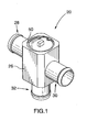
- FIGURE 1 is a perspective view of a valve according to one embodiment of the invention.
- FIGURE 2 is an exploded perspective view of the structure of FIGURE 1 ;
- FIGURE 3 is a view of encircled area 3 of FIGURE 2 ;
- FIGURE 4 is a top view of the structure of FIGURE 3 ;
- FIGURE 5 is a section along 5-5 of FIGURE 4 .
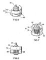
- FIGURE 6 is an enlarged view of encircled area 6 of FIGURE 2 ;
- FIGURE 7 is a perspective view of the structure of FIGURE 6 , from another vantage point;
- FIGURE 8 is a side view of the structure of FIGURE 6 ;
- FIGURE 9 is an enlarged view of encircled area 9 of FIGURE 2 ;
- FIGURE 10 is a perspective view of the structure of FIGURE 9 , from another vantage point;
- FIGURE 11 is a perspective view of the structure of FIGURE 9 , from another vantage point;
- FIGURE 12 is a perspective view of the structure of FIGURE 9 , from another vantage point;
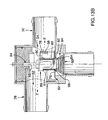
- FIGURE 13A is a view similar to FIGURE 5 of the valve of FIGURE 1 , showing a wax motor in a fully retracted arrangement and the valve in a bypass configuration thereof;
- FIGURE 13B is a view similar to FIGURE 13A , showing the wax motor in a partially extended arrangement and the valve in a flowthrough configuration thereof;
- FIGURE 13C is a view similar to FIGURE 13B , showing the wax motor in a fully extended arrangement and the valve in the flowthrough configuration thereof;
- FIGURE 14 is a schematic view of a valve similar to the valve of FIGURE 1 in use in an engine block casting;
- FIGURE 15 is a schematic view of a valve similar to the valve of FIGURE 1 in use in a radiator;
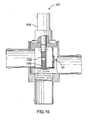
- FIGURE 16 is a view, similar to FIGURE 13A , of a valve according to a second embodiment of the invention.
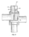
- FIGURE 17 is a view, similar to FIGURE 13A , of a valve according to a third embodiment of the invention.
- FIGURE 18 is a view, similar to FIGURE 13A , of a valve according to a fourth embodiment of the invention.
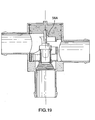
- FIGURE 19 is a view, similar to FIGURE 13A , of a valve according to a fifth embodiment of the invention.
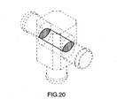
- FIGURE 20 is a phantom view of the valve of FIGURE 1 , showing a blacklined volume which represents the extent to which the flow ports are directly aligned;
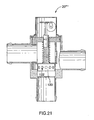
- FIGURE 21 is a view, similar to FIGURE 19 , of a valve according to a sixth embodiment of the invention.
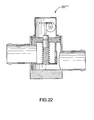
- FIGURE 22 is a view, similar to FIGURE 19 , of a valve according to a seventh embodiment of the invention.
- FIGURE 23 is a perspective view of a cartridge structure according to a seventh embodiment of the invention.
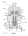
- FIGURE 24 is a cross-sectional view of the structure of FIGURE 23 ;
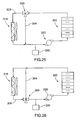
- FIGURE 25 is a schematic view of a valve according to an embodiment of the present invention in a first exemplary use
- FIGURE 26 is a view similar to FIGURE 25 of a second exemplary use
- FIGURE 27 is a perspective view of an alternative embodiment of the structure of FIGURE 11 , as present in FIGURES 23 , 24 ;;
- FIGURE 28 is a side view of an alternative embodiment of the structure of FIGURE 6 , as present in FIGURES 23 , 24 , in use with the structure of FIGURE 27 ;
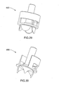
- FIGURE 29 is a perspective view of a further alternative embodiment of the structure of FIGURE 6 ;
- FIGURE 30 is a perspective view of a yet further alternative embodiment of the structure of FIGURE 6 .
- a valve for use with a fluid such as engine coolant is illustrated and is designated by the general reference numeral 20.
- the valve 20 comprises a housing 22 and a valve cartridge 24.
- This housing 22 is of aluminum and includes a central portion 26 defining an open receptacle and three spigots 28,30,32 extending therefrom in a tee arrangement, each leading into the open receptacle.
- Two of the spigots 28,30 are substantially parallel and opposed to one another.
- the third spigot 32 extends transversely to the others.
- the inner surface 34 of the receptacle has a peripheral groove 36 extending therearound.
- the valve cartridge 24 includes an aluminum insert 38, an aluminum plug 40, an actuator 42 and a rubber O-ring 44.
- the insert 38 has a peripheral groove 48 which receives the O-ring 44 and can be fitted in the receptacle 26 and secured in place with a spring clip 50 which interfits in groove 36, as indicated in FIGURE 13A . So secured, the O-ring 44 sealingly engages each of the insert 38 and the inner surface 34 of the receptacle 26, to seal the insert 38 and housing 22 to one another, such that the insert 38, the O-ring 44 and the housing 22 together define a valve body.
- the valve body has a pair of flow ports 52,54, an interior surface 56, an axis X-X, an interior wall 58, a further port 60, a first valve seat 62 and a second valve seat 64.
- the flow ports 52,54 are spaced-apart from, substantially opposed to and substantially aligned with one another, and communicate one each with the parallel spigots 28,30.
- Flow ports 52,54 are each orientated substantially transverse to axis X-X.
- substantially alignment of the flow ports 52,54 means that, if one were to project the flow ports across the valve body parallel to their respective flow directions, the projections would intersect to a substantial extent, as indicated by FIGURE 20 , wherein the valve is shown in phantom and the volume of intersection is indicated by the blacklined volume.
- the interior surface 56 defines an interior chamber 66 of the valve body which is disposed between the flow ports 52,54 and communicates therewith.
- the axis X-X is aligned with the third spigot 32, and orientated transversely to a flowthrough direction Y-Y with which the flow ports 52,54 are substantially aligned.
- the interior wall 58 is a generally semi-cylindrical structure centred about the axis X-X; extends axially, partially across the interior chamber 66; defines, in combination with the interior surface 56, an interior opening 68; and has a wall opening 70 therethrough.
- Wall opening 70 is opposed to and aligned with flow port 52, i.e. wall opening 70 and flow port 52 present to one another.
- Flow port 54 and wall opening 70 are aligned, i.e. if one were to project flow port 54 parallel to its flow direction (not shown), the projection would intersect with wall opening 70 to a substantial extent.
- the interior wall 58 in combination with portions of the valve body, notionally defines a tubular structure, in which the interior opening 68 defines an open end and of which the interior wall 58 defines a side wall.
- the interior opening 68 provides for communication between a first subchamber 72 of the interior chamber 66 to which one 52 of the flow ports leads and a second subchamber 74 of the interior chamber 66 to which the other 54 of the flow ports leads.
- the second subchamber 74 extends partially around the side wall and beyond the open end of the tubular structure described hereinbefore.
- the wall opening 70 in the interior wall 58 also leads between the first 72 and second 74 subchambers. Both the interior wall 58 and the wall opening 70 thereof each circumscribe an angle of about 180°.
- the further port 60 provides for communication between second subchamber 74 and third spigot 32.
- the first valve seat 62 surrounds the further flow port 60 and is defined by the interior surface 56 of the valve.
- the second valve seat 64 surrounds the interior opening 68, is axially spaced from the first valve seat 62 and is defined by the interior surface 56 and by the end of the interior wall 58.
- the plug 40 has a circular base portion 76 and a semi-cylindrical sidewall portion 78 extending from the base portion 76.
- Sidewall portion 78 has a bisected plug opening 80 therein, and each of the side portion 78 and the plug opening 80 circumscribe an angle of about 180°.
- the plug 40 is shown in a first position in the interior chamber 66.
- base portion 76 and side portion 78 are both centred about the axis X-X, such that side portion 78 is concentric with the interior wall 58, the interior wall 58 is nested within plug 40, the base portion 76 is seated on the second valve seat 64, the interior wall 58 overlies the plug opening 80 and the side portion 78 overlies the wall opening 70 to at least substantially isolate the first subchamber 72 of the interior chamber 66 from the second subchamber 74.
- This defines an arcuate (or bypass, when the valve is used as a bypass valve) flow configuration of the valve 20, whereat the valve 20 defines a further flow path B-B through the valve body between spigots 30,32 via flow port 54 and further port 60.
- the actuator 42 is for axially moving the plug 40 in the interior chamber between the first position shown in FIGURE 13A and a second position shown in FIGURE 13B .
- the base portion 76 is seated on the first valve seat 62, to at least substantially occlude the further port 60.
- This defines a flowthrough configuration of the valve 20, whereat the valve 20 defines a primary flow path F-F through the valve body between spigots 28,30 via flow ports 52,54.
- the side portion 78 of the plug 40 and the interior wall 58 are arranged behind one another, to maximize the area through which fluid may flow.
- the primary flow path is a split-flow arrangement, with a first flow path between ports 52,54 being by way of the wall opening 70 and a second flow path between ports 52,54 being through the open end of the tubular structure, i.e. interior opening 68 and the plug opening 80. In this position of the plug 40, the plug opening 80 and flow port 54 are aligned.
- the actuator 42 shown includes a wax motor 82, a frustoconical stainless steel return spring 84, a cylindrical stainless steel override spring 86 and an aluminum tubular sleeve 88.
- the sleeve 88 has annular flanges 90,92 extending around each end and extends through an opening 98 in the circular base portion 76. The flanges 90,92 provide for the sleeve 88 to be captured by the circular base portion 76.
- the wax motor 82 is of a conventional type which includes a shell 91 having an enlarged head 89 from which a shaft 93 protrudes, the shaft 93 moving in response to thermally-induced expansion of the wax-like material (not shown) contained within the shell 91.
- the motor 82 is fitted in the sleeve 88, and a C-clip 194 is secured thereto, such that enlarged head 89 and the C-clip 194 capture therebetween the sleeve 88.
- the shaft 93 projects from the wax motor 82 into a socket or recess 94 formed in the insert 38.
- the return spring 84 extends between the sleeve flange 92 which is captured by the C-clip 194 and the bypass port 60.
- the override spring 86 is fitted around the sleeve 88 and extends between the sleeve flange 90 which is captured by the enlarged head 89 and the base portion 76 of the plug 40.
- the wax-like material in the motor 82 When the temperature of the wax-like material in the motor 82 reaches or exceeds the actuator set point temperature, the wax-like material expands. This causes shaft 93 to be partially expelled from the shell 91. As the shaft 93 cannot extend through the socket 94, extension of the shaft 93 from the shell 91 is accommodated by movement of the shell 91, and the sleeve 88 by which it is mechanically captured, away from the socket 94. Initially, as the shell 91 moves away from the socket 94, bias provided by the override spring 86 causes the base portion 76 to remain engaged against flange 92 during such movement, such that movement of the shell 91 corresponds to movement of the plug 40. In the course of such movement, the plug 40 will ultimately reach the second position, as shown in FIG.
- the conical return spring 84 will drive the shell 91 back over the shaft 93. Until such time as flange 92 of the sleeve 88 engages base portion 76, bias provided by override spring 86 will maintain base portion 76 seated against the first valve seat 62. Expansion of the conical spring 84 beyond that point will result in movement of the sleeve 88 and plug 40 together, during which movement, the interior wall 58 telescopes into the plug 40. Ultimately, the plug 40 returns to the first position, and further movement is arrested by engagement of the base portion 76 with the second valve seat 64.
- the valve of FIGURE 1 is used as a bypass valve and deployed in an automobile cooling circuit.
- spigot 30 receives a hose (not shown) through which coolant from the engine is received
- spigot 28 is coupled by a hose to the radiator inlet (neither shown)
- the further spigot 32 is coupled by a hose through which coolant is delivered to the engine.
- the wax-motor is maintained in the fully-retracted position
- the plug is disposed in the first position and the valve is disposed in the bypass configuration, such that most of the coolant follows path B-B back to the engine.
- port 54 is an inlet port and ports 52, 60 are outlet ports.
- leak paths exist in the seal between the base portion 76 of the plug 40 and the second valve seat 64, in the junction between interior portion 58 and side portion 78, in the junction between sleeve 88 and opening 98 in the base portion 76 and in the junction between the shell 91 and the sleeve 88.
- the wax motor 82 is not entirely isolated from the flow, so as to be susceptible to actuation when the flow temperature exceeds the wax set point.
- the plug 40 moves to the second position and the valve assumes the flowthrough configuration, such that most of the coolant follows flow path F-F through the radiator before being returned to the engine.
- leak paths will exist, in the seal between the base portion 76 of the plug 40 and the first valve seat 64, in the junction between interior wall 58 and side portion 78, in the junction between sleeve 88 and opening 98 in the base portion 76 and in the junction between the shell 91 and sleeve 88.
- FIGURE 14 A similar use is shown schematically in FIGURE 14 .
- a valve 20' similar to that of FIGURE 1 but lacking spigots is fitted in an engine block casting 99, with the flow ports forming part of the coolant circuit (not shown) from the engine to the radiator and the bypass port coupled to a circuit (not shown) which bypasses the radiator and returns to the engine.
- the operation of this valve 20' is functionally identical to the valve 20 and use thereof previously described, and thus is not further described herein.
- FIGURE 15 A further use of the valve 20' of FIGURE 14 is shown schematically in FIGURE 15 .
- the valve 20' is fitted in a radiator 101, with the flow ports forming part of a heat exchanging circuit 103 through which coolant is caused to traverse the heat exchanger 101 and shed heat before returning to the engine, and the bypass port forming part of a circuit 105 which bypasses the heat-exchanging portion of the radiator in its return to the engine.
- the operation of this valve 20' is functionally identical to the valve 20 and uses thereof previously described, and thus is not further described herein.
- the advantageous flow characteristics of the present valve derive from the shape of the valve and its components.
- the primary flow path is substantially parallel to the flows leading to and from the valve.
- each of the primary and further flow paths is free of substantial constrictions over their respective lengths owing, inter alia, to the relatively large volume of the second subchamber 74 which the flow traverses in the arcuate or bypass configuration of the valve, and to the relatively large area of openings 70,80 (similar in size to the area of each of the flow and further ports 52,54,60) through which the flow traverses in the flowthrough configuration of the valve.
- the shape of the second subchamber 74 of the interior chamber specifically, the upper portion thereof having a C-shaped or arcuate cross-section, which permits the flow entering from flow port 54 to spread out, around the side wall 78/interior wall 58, before passing under the base portion 76 and exiting the valve through the port 60.
- FIGURES 16-18 Various other embodiments of the valve are shown in FIGURES 16-18 . These valves are similar in function to the valve of FIGURES 1-13C , but whereas the valve of FIGURES 1-13C employs a wax motor to drive the plug between the first and second positions, these valves employ other forms of actuators to accomplish the same function.
- FIGURE 16 shows a valve 20" wherein the plug 40 has a threaded post 100 axially extending therefrom which is received by an internally-threaded driveshaft 102 coupled to a motor 104.
- the motor 104 can rotate the drive shaft 102, which rotates about the threaded post 100, so as to result in axial movement of the post 100 and consequent movement of the plug 40 between the first and second positions.
- FIGURE 17 shows a valve 20'" wherein a rack 106 extends from the plug 40, a pinion 108 is in mesh with the rack 106 and a motor 110 is drivingly coupled to the pinion 108.
- the motor 110 rotates the pinion 108 which drives the rack 106 axially to move the plug 40 between the first and second positions.
- FIGURE 18 shows yet another valve 20"" wherein a cam follower 112 is coupled to the plug 40, a cam 114 is engaged with the cam follower and a stepper motor 116 is coupled to the cam 114.
- the stepper motor 116 rotates the cam 114 to engage the cam follower 112 and drive the plug axially between the first and second positions.
- valves 20", 20"', 20"" operate in a manner substantially similar to valves 20 and 20', further description as to their respective construction and operation is neither necessary nor provided.
- valve 20""' of FIGURE 21 which is similar to the valve of FIGURE 18 , but also includes a tubular skirt 120 which extends from the plug and telescopes into the further port.
- bypass flow through the further port is restricted, by virtue of its need to pass through holes 122 defined in the skirt 120.
- holes 122 By changing the shapes/sizes of holes 122, the flow characteristics of this valve can be modified at different points during movement between the first and second positions, to allow flow to be metered or linearized.
- the skirt provides prealignment of the plug, which can assist in sealing in the flowthrough position, avoid binding, avoid deformation of the shaft and improve uniformity of the bypass flow stream to, inter alia, balance interior pressures in the valve and improve sealing in the bypass position.
- pressures that will be experienced in the valve interior in use at various positions between full bypass and no bypass will be a function of the flow resistance in the bypass and flowthrough circuits.
- a skirt can be used to balance the aggregate pressure drop, inclusive of the valve and the circuits, such that flow is directed towards the higher pressure circuit as a relatively more linear function of the position of the plug.
- the skirt could have a toothed (as per the embodiment 500 shown in Fig. 29 ), scalloped (as per the embodiment 600 shown in Fig. 30 ) or otherwise irregular end for flow proportioning, and (iii) the holes, teeth, scallops or irregularities in the skirt could be spaced otherwise than radially-equally, for example, the holes, teeth, scallops or irregularities could be concentrated in one area, for flow contouring purposes.
- a yet further modification is shown in the modified valve 20""" of FIGURE 22 .
- This valve is substantially similar to the valve of FIGURE 18 , but lacks the further "bypass" port.
- FIGURES 23 and 24 show the cartridge portion 200 of a further embodiment of the valve of the present invention.
- This cartridge portion 200 bears some similarity to the valve cartridge of FIGURE 16 , particularly in that each employ a rotating element to secure linear motion of the plug 40.
- plug 40 has an externally-threaded post 100 and the shaft 102 rotates and is internally-threaded
- an externally threaded shaft 102' is provided, which engages within an externally threaded shaft extension 206; the extension 206, in turn, is engaged within an internally threaded post 100'.
- the threaded shaft 102' does not rotate, and indeed, a restraint device 220 in the form of a key/keyway arrangement is provided, to arrest rotation of shaft 102', but rather, is threadingly engaged by an internally-threaded rotor 230 which rotates under magnetic control of a stator coil 218 forming part of the stepper motor 216.
- Upper and lower bearings 240 retain the rotor 230 in position while permitting free rotation.
- the cartridge 200 includes a biasing spring 204, for urging the plug 40 towards the flowthrough position.
- the sidewall portion 78 is adapted for better sealing of the wall opening 70, via axially-spaced spaced apart edges 78A, 78B which engage, in the bypass position of the plug 40, respectively, with a lip 58A formed on the interior wall 58 and a groove 202 formed in the valve body.
- Axial grooves 400 are also formed in the valve body, in which the sidewall portion 78 slides during movement between the bypass and flowthrough positions, and an upstanding lip 205 is formed on the base portion 76 which engages groove 207 formed in the valve body in the bypass position of the plug 40.
- valves according to the present invention can be created that move reliably to one port (i.e. bypass or flowthrough configuration, as desired) only in low flow conditions.
- the valve does not immediately assume the failsafe position, which could result in "water hammer" damage.
- the appropriate balance must be struck between (i) spring bias and stepper static friction; and (ii) hydraulic forces associated with differential pressure between the first and second subchambers.
- a valve using the cartridge of FIGURES 23 , 24 can be used, for example, in the manner contemplated by FIGURE 15 , i.e. as a radiator bypass valve for an internal combustion engine.
- this valve can be produced to embody both (i) proportionality, i.e. incremental selectivity between flowthrough and bypass; and (ii) a fail-safe, this valve could also be employed, in combination with (not shown) a variable speed pump and fan, to conspicuous advantage in fuel cell applications, wherein precise control of stack temperature under a range of duty cycles is critical for proper functioning.
- FIGURE 25 schematically shows such a valve 300 in an inlet diverting configuration for a coolant circuit.
- the valve 300 has one inlet port and two outlet ports.
- the coolant flow driven by the pump 320, enters the valve 300 from the fuel cell stack 302 or other heat source and is split into the outlet ports going towards the bypass line 304 and radiator line 306.
- This valve diverts the inlet stream to either the radiator 316, the bypass line 304 or a combination thereof, if the plug is caused to assume a position intermediate the bypass and flowthrough position.
- FIGURE 26 schematically shows such a valve 300 in an inlet mixing configuration, in which the valve 300 has two inlet ports and one outlet port.
- the inlet fluid flows entering the valve from the bypass line 304 and the radiator line 306 are joined together and mixed into the valve outlet stream, with the valve controlling the relative amount of flow through each of the radiator 316 and bypass 304.
- valve in combination with pump speed and radiator fan speed, allows the temperature of the heat source to be controlled by diverting flow between radiator and bypass loop.
- valve oscillation not only permits fine adjustment to be made to the flow distribution, for precise tuning of temperatures, but also can be utilized to avoid valve oscillation.
- the coolant in the heat exchanger would stay very cold.
- a large slug of cold coolant would enter the heat exchanger. This would have an impact on the operation of any fuel cell or other temperature sensitive equipment in the circuit, and could also trigger an immediate reversion of the valve to the bypass configuration i.e. valve oscillation [i.e. sensors could detect the low temperature coolant slug and construe this as a need for heating].
- valve of FIGURE 24 could be operated so as to move incrementally between flow-through and bypass configurations, so as to avoid the contemplated cold-slug.
- this functionality may be further enhanced through the use of a calibrated leak, for example, a hole of a predetermined size (not shown) through the base portion 76 or other of the components of the valve, and/or through the use of a skirt 120 of the general type described with reference to FIGURE 21 .
- valves according to FIGURE 24 permits the circuit to be adjusted such that, in the event of signal loss to the stepper motor, or power failure to the stepper motor, the valve automatically reverts to a configuration providing maximum flow to the radiator, to avoid overheating of the fuel cell stack and the associated damage that would cause.
- valve is herein sometimes shown and illustrated as a bypass valve, wherein an input or inlet flow is directed to one of two outputs or outlets
- valve could be used as a mixing valve, wherein flow is selectively received from one of two inputs and delivered to a single output.
- port 52 is deployed as an inlet port
- fluid pressure may tend to separate walls 78,58, and to avoid this, a skirt as shown in FIGURE 21 may be advantageously utilized to stabilize the plug.
- an actuator capable of moving the plug partially between the first and second positions such as one of the actuators shown in FIGURES 16-18 and 24 , would be used in substitution for wax motors which, while relatively inexpensive, robust and reliable in comparison to the actuators of FIGURES 16-18 and 24 , generally lack proportional responsiveness, i.e. reliably move only between the fully retracted and the fully extended arrangements.
- valves illustrated and described have relatively good flow characteristics, improvements are contemplated to be achievable through interior contouring or streamlining, as suggested in FIGURE 19 , wherein a portion 56A of the interior surface 56 has been contoured for flow conditioning.
- valve of FIGURES 1-13C is indicated to be constructed of steel, aluminum and rubber, it will be evident that other materials, such as plastics, could readily be employed.
- valves shown and described herein are indicated to be of a cartridge type, so as to permit [[for eg]] ready removal and replacement of the moving parts of the valve in the event of failure or excess wear, it will be evident that a cartridge-type construction need not be employed.
- plug opening shown and described is indicated to be bisected, it will be evident that this is not necessary.
- the plug opening could equally be defined by a single aperture, or by three or more apertures, and the apertures could be shaped, for flow balancing or linearization purposes in a manner analogous to that described with reference to the skirt 120.
- the wall opening 70 could similarly be shaped, for the same purposes.
- side portion of the plug and the interior portion are herein indicated to be semi-cylindrical and to circumscribe at least about 180°, it is not necessary and indeed, not always desirable to have perfect semi-cylindrical shapes.
- interior wall is herein shown to partially divide the interior chamber, it is contemplated that the interior wall could extend fully across the interior chamber.
- the plug might telescope interiorly into the first subchamber, and some form of perforation or aperture in the interior wall could be provided, to mate with the plug opening when the plug is at the second position.
- valves according to the invention can be configured to assume either full bypass or no bypass in the event of signal loss.
- fail-safe functionality is described with particularity in the context of the embodiment of FIG. 24 , it should also be understood that, with suitable modifications to thread pitch and the like, the same functionality can be provided in the embodiment of FIG. 16 .
- valves according to the present invention can employ electronic linear actuators, and fail-safe functionality can also be provided therein.
Landscapes
- Engineering & Computer Science (AREA)
- General Engineering & Computer Science (AREA)
- Mechanical Engineering (AREA)
- Chemical & Material Sciences (AREA)
- Combustion & Propulsion (AREA)
- Physics & Mathematics (AREA)
- General Physics & Mathematics (AREA)
- Automation & Control Theory (AREA)
- Fluid Mechanics (AREA)
- Multiple-Way Valves (AREA)
- Mechanically-Actuated Valves (AREA)
- Temperature-Responsive Valves (AREA)
- Electrically Driven Valve-Operating Means (AREA)
Applications Claiming Priority (2)
| Application Number | Priority Date | Filing Date | Title |
|---|---|---|---|
| US11/695,985 US7721973B2 (en) | 2007-04-03 | 2007-04-03 | Valve |
| PCT/CA2008/000646 WO2008119189A1 (en) | 2007-04-03 | 2008-04-03 | Valve |
Publications (3)
| Publication Number | Publication Date |
|---|---|
| EP2132468A1 EP2132468A1 (en) | 2009-12-16 |
| EP2132468A4 EP2132468A4 (en) | 2012-01-04 |
| EP2132468B1 true EP2132468B1 (en) | 2013-02-27 |
Family
ID=39807771
Family Applications (1)
| Application Number | Title | Priority Date | Filing Date |
|---|---|---|---|
| EP20080733725 Not-in-force EP2132468B1 (en) | 2007-04-03 | 2008-04-03 | Valve |
Country Status (6)
| Country | Link |
|---|---|
| US (1) | US7721973B2 (enExample) |
| EP (1) | EP2132468B1 (enExample) |
| JP (1) | JP5014485B2 (enExample) |
| CN (1) | CN101668972B (enExample) |
| CA (1) | CA2651289C (enExample) |
| WO (1) | WO2008119189A1 (enExample) |
Cited By (1)
| Publication number | Priority date | Publication date | Assignee | Title |
|---|---|---|---|---|
| WO2019115946A1 (fr) * | 2017-12-13 | 2019-06-20 | Novares France | Vanne thermostatique |
Families Citing this family (34)
| Publication number | Priority date | Publication date | Assignee | Title |
|---|---|---|---|---|
| US7540431B2 (en) * | 2004-11-24 | 2009-06-02 | Dana Canada Corporation | By-pass valve for heat exchanger |
| US8690072B2 (en) * | 2007-04-03 | 2014-04-08 | Dana Canada Corporation | Radiator bypass valve |
| US9098095B2 (en) * | 2007-07-17 | 2015-08-04 | Jiffy-Tite Co., Inc. | Cooler bypass assembly |
| US8991719B2 (en) * | 2009-07-09 | 2015-03-31 | Dana Canada Corporation | Low pressure drop thermal by-pass valve |
| US8978992B2 (en) * | 2009-09-14 | 2015-03-17 | Jiffy-Tite Company, Inc. | Cooler bypass apparatus and installation kit |
| CN101706010B (zh) * | 2009-11-12 | 2011-08-24 | 路达(厦门)工业有限公司 | 温控混合阀结构 |
| US8408518B2 (en) * | 2009-11-13 | 2013-04-02 | Fisher Controls International, Llc | Electric actuators having internal load apparatus |
| JP5464357B2 (ja) * | 2010-03-23 | 2014-04-09 | 三菱自動車工業株式会社 | 車載用電池パック |
| ITMI20100321U1 (it) * | 2010-10-22 | 2012-04-23 | Caleffi Spa | Dispositivo termostatico valvolare anticondensa per impianti termici. |
| CA3096237C (en) | 2010-11-04 | 2023-01-24 | Magarl, Llc | Electrohydraulic thermostatic control valve |
| DE102010064304A1 (de) * | 2010-12-29 | 2012-07-05 | Robert Bosch Gmbh | Ventil zur Steuerung von Volumenströmen |
| US9423036B1 (en) * | 2011-03-29 | 2016-08-23 | Danfoss A/S | Thermostatic radiator valve insert |
| EP2535622A1 (en) * | 2011-06-15 | 2012-12-19 | Delphi Technologies Holding S.à.r.l. | Valve assembly |
| SE536185C2 (sv) * | 2011-11-29 | 2013-06-18 | Scania Cv Ab | System för reglering av vätskeflödet i ett fordon |
| CN102425687B (zh) * | 2011-12-02 | 2013-07-31 | 常州有容电子有限公司 | 自动温度调节阀 |
| DE112013001039B4 (de) * | 2012-02-20 | 2021-08-19 | Hanon Systems | Ventil mit integriertem Motorbypass-Failsafe aus Wachs |
| SE536466C2 (sv) * | 2012-04-05 | 2013-11-26 | Scania Cv Ab | Termostatanordning och kylsystem |
| US9879794B2 (en) * | 2013-06-25 | 2018-01-30 | Magna powertrain gmbh & co kg | Valve with fail-safe mechanism |
| DE102013107293B4 (de) * | 2013-07-10 | 2020-02-20 | Pierburg Gmbh | Steuerventileinheit für Kühlkreisläufe eines Kraftfahrzeugs |
| JP5927729B2 (ja) * | 2013-11-06 | 2016-06-01 | 本田技研工業株式会社 | 流路部材 |
| US9772632B1 (en) * | 2013-11-25 | 2017-09-26 | Richard Michael Ihns | Bypass valve |
| KR200474396Y1 (ko) | 2013-12-20 | 2014-09-15 | 베어티씨 주식회사 | 자동변속기 오일의 온도 조절장치용 바이패스 어셈블리 |
| KR101542989B1 (ko) * | 2014-04-30 | 2015-08-07 | 현대자동차 주식회사 | 차량용 밸브 |
| KR101567434B1 (ko) * | 2014-07-31 | 2015-11-12 | 인지컨트롤스 주식회사 | 페일 세이프티 냉각수조절밸브 |
| JP6080182B1 (ja) * | 2015-12-02 | 2017-02-15 | 日本電産サンキョーシーエムアイ株式会社 | モータ駆動の開閉弁 |
| CN108027085B (zh) * | 2016-03-02 | 2020-02-14 | 达纳加拿大公司 | 双流体阀装置和结合其的用于控制两个流体流的系统 |
| WO2017155483A1 (en) * | 2016-03-07 | 2017-09-14 | Kirpart Otomotiv Parcalari Sanayi Ve Ticaret Anonim Sirketi | A thermal management module with loose slider valve |
| DE102017114195B4 (de) * | 2017-06-27 | 2023-08-24 | Volkswagen Aktiengesellschaft | Thermostatventil für einen Kühlkreislauf |
| FR3077860B1 (fr) * | 2018-02-09 | 2021-01-22 | Novares France | Vanne thermostatique a triple clapets |
| US11092982B2 (en) * | 2018-07-23 | 2021-08-17 | Schaeffler Technologies AG & Co. KG | Temperature sensor for coolant control valve |
| FR3090735B1 (fr) * | 2018-12-19 | 2024-02-02 | Renault Sas | Dispositif de refroidissement d’huile pour un moteur. |
| DE102020204271A1 (de) * | 2019-04-05 | 2020-10-08 | Dana Canada Corporation | Wärmetauscheranordnung mit integriertem Ventil und Druckbypass |
| KR20210098087A (ko) | 2020-01-31 | 2021-08-10 | 현대자동차주식회사 | 유량제어밸브 장치 |
| KR20210119659A (ko) * | 2020-03-25 | 2021-10-06 | 현대자동차주식회사 | 유량제어밸브 장치 |
Family Cites Families (52)
| Publication number | Priority date | Publication date | Assignee | Title |
|---|---|---|---|---|
| US3682380A (en) * | 1970-09-10 | 1972-08-08 | Ahmad Aziz | Temperature control in fluid systems |
| GB1501413A (en) * | 1974-06-06 | 1978-02-15 | Sullair Europ Corp | Flow regulating valve assemblies |
| US3907199A (en) * | 1974-11-18 | 1975-09-23 | Ford Motor Co | Combination engine cooling system and passenger compartment heating system for an automotive vehicle |
| JPS52162533U (enExample) * | 1976-06-02 | 1977-12-09 | ||
| JPS5338036U (enExample) * | 1976-09-08 | 1978-04-03 | ||
| US4508132A (en) * | 1979-09-10 | 1985-04-02 | Microphor, Inc. | Temperature controlled valve mechanism and method |
| US4356833A (en) * | 1979-09-10 | 1982-11-02 | Microphor, Inc. | Temperature controlled valve mechanism and method |
| JPS6025020Y2 (ja) * | 1982-03-31 | 1985-07-26 | アイシン精機株式会社 | サ−モバルブ |
| JPS6037670U (ja) * | 1983-08-24 | 1985-03-15 | 日本サ−モスタツト株式会社 | 温度調節弁 |
| US4537346A (en) * | 1983-10-17 | 1985-08-27 | Standard-Thomson Corporation | Fail-safe oil flow control apparatus |
| US4562953A (en) * | 1984-10-01 | 1986-01-07 | Standard-Thomson Corporation | Valve seat structure for automotive thermostatic fluid control valve device |
| JPS6272414U (enExample) * | 1985-10-25 | 1987-05-09 | ||
| US4846219A (en) | 1988-01-15 | 1989-07-11 | Parker-Hannifin Corporation | Pressure relief by pass control valve |
| US5011074A (en) | 1990-07-20 | 1991-04-30 | Lawler Manufacturing Co., Inc. | Thermostatic mixing valve with thermostat failure compensation |
| US5423373A (en) * | 1991-03-08 | 1995-06-13 | Arctic Fox Heaters, Inc. | Bypass device for reservoir and intake conduit heating of power fluids |
| DE9309447U1 (de) | 1993-06-25 | 1993-09-16 | Hans Sasserath & Co Kg, 41352 Korschenbroich | Temperaturgesteuertes Dreiwege-Mischventil |
| JP3292862B2 (ja) | 1994-10-14 | 2002-06-17 | 株式会社テイエルブイ | 感温弁を用いた熱交換装置 |
| US5755283A (en) | 1995-12-08 | 1998-05-26 | Gas Reasearch Institute | Combined thermostat and selector valve arrangement for gas driven heat pump systems |
| JPH1077840A (ja) * | 1996-08-30 | 1998-03-24 | Denso Corp | 冷却水制御弁および内燃機関の冷却水回路 |
| US5896833A (en) | 1996-08-30 | 1999-04-27 | Denso Corporation | Cooling water circuit system and cooling water control valve |
| DE19637818C1 (de) * | 1996-09-17 | 1998-04-16 | Laengerer & Reich Gmbh & Co | Thermostatventileinheit |
| DE29619609U1 (de) * | 1996-11-12 | 1997-01-16 | Behr Thermot-Tronik Gmbh & Co., 70806 Kornwestheim | Thermostatventil |
| DE19725222A1 (de) * | 1997-06-15 | 1998-12-17 | Behr Thermot Tronik Gmbh & Co | Thermostatventil |
| GB2325724B (en) * | 1997-07-04 | 1999-04-21 | Amot Controls Ltd | Device |
| US6253837B1 (en) * | 1998-03-23 | 2001-07-03 | Long Manufacturing Ltd. | By-pass values for heat exchanger |
| US5950576A (en) * | 1998-06-30 | 1999-09-14 | Siemens Canada Limited | Proportional coolant valve |
| FR2801958B1 (fr) * | 1999-12-07 | 2002-03-01 | Vernet Sa | Dispositif thermostatique motorise a element thermostatique de securite |
| US6435143B2 (en) | 2000-03-01 | 2002-08-20 | Thomas J. Hollis | Three-way solenoid valve for actuating flow control valves in a temperature control system |
| US6286464B1 (en) | 2000-06-09 | 2001-09-11 | Robertshaw Controls Company | Water heating system |
| JP4408539B2 (ja) * | 2000-07-25 | 2010-02-03 | 日本サーモスタット株式会社 | サーモスタットのケース構造 |
| JP4368043B2 (ja) * | 2000-07-25 | 2009-11-18 | 日本サーモスタット株式会社 | シール部材を用いたサーモスタットの取付け構造 |
| DE10053699B4 (de) * | 2000-10-25 | 2010-11-11 | Behr Thermot-Tronik Gmbh | Regelventil |
| US6929187B2 (en) | 2000-10-25 | 2005-08-16 | Grundfos Pumps Manufacturing Corporation | Water control fixture having thermostatically controlled bypass valve |
| US6536464B1 (en) * | 2000-10-25 | 2003-03-25 | Grundfos Pumps Manufacturing Corporation | Thermostatically controlled bypass valve and water circulating system for same |
| DE10104179B4 (de) * | 2001-01-23 | 2013-10-31 | Behr Thermot-Tronik Gmbh | Thermostatventil mit einem Ringschieber |
| US6634322B2 (en) | 2001-04-12 | 2003-10-21 | Cold Fire, Llc | Heat exchanger tempering valve |
| CA2383579A1 (en) * | 2001-04-26 | 2002-10-26 | Tesma International Inc. | Electromagnetically controlled butterfly thermostat valve |
| US20030019620A1 (en) | 2001-07-30 | 2003-01-30 | Pineo Gregory Merle | Plug bypass valves and heat exchangers |
| US6681805B2 (en) | 2001-11-28 | 2004-01-27 | Ranco Incorporated Of Delaware | Automotive coolant control valve |
| KR20030067942A (ko) * | 2002-02-09 | 2003-08-19 | 현대자동차주식회사 | 가변제어방식의 전자식 서모스탯 |
| US6539899B1 (en) | 2002-02-11 | 2003-04-01 | Visteon Global Technologies, Inc. | Rotary valve for single-point coolant diversion in engine cooling system |
| DE10206359A1 (de) * | 2002-02-14 | 2003-09-04 | Daimler Chrysler Ag | Thermostatventil sowie Verfahren zur Steuerung eines Kühlmittelkreislaufes |
| US6793012B2 (en) | 2002-05-07 | 2004-09-21 | Valeo, Inc | Heat exchanger |
| JP2004052752A (ja) * | 2002-05-28 | 2004-02-19 | Nissan Motor Co Ltd | エンジンの冷却装置 |
| US7028712B2 (en) | 2002-07-17 | 2006-04-18 | Fisher Controls International Llc. | Skirt guided globe valve |
| CA2431717C (en) * | 2002-12-10 | 2012-10-16 | Tesma International Inc. | Proportional valve with linear actuator |
| US20040118462A1 (en) | 2002-12-19 | 2004-06-24 | Baumann Hans D. | Control valve with low noise and enhanced flow characteristics |
| US6799631B2 (en) | 2003-01-09 | 2004-10-05 | Delphi Technologies, Inc. | Heat exchanger with integrated flow control valve |
| JP4400909B2 (ja) * | 2003-04-04 | 2010-01-20 | 日本サーモスタット株式会社 | サーモスタット装置 |
| US6772958B1 (en) * | 2003-04-28 | 2004-08-10 | Rostra Precision Controls, Inc. | Thermal flow control valve |
| CA2459088C (en) | 2004-02-27 | 2012-08-21 | Dana Canada Corporation | Leak-resistant solenoid valve |
| CN100458251C (zh) * | 2004-11-18 | 2009-02-04 | 日本恒温装置株式会社 | 恒温装置 |
-
2007
- 2007-04-03 US US11/695,985 patent/US7721973B2/en not_active Expired - Fee Related
-
2008
- 2008-04-03 EP EP20080733725 patent/EP2132468B1/en not_active Not-in-force
- 2008-04-03 WO PCT/CA2008/000646 patent/WO2008119189A1/en not_active Ceased
- 2008-04-03 CA CA 2651289 patent/CA2651289C/en not_active Expired - Fee Related
- 2008-04-03 CN CN2008800097635A patent/CN101668972B/zh not_active Expired - Fee Related
- 2008-04-03 JP JP2010501342A patent/JP5014485B2/ja not_active Expired - Fee Related
Cited By (2)
| Publication number | Priority date | Publication date | Assignee | Title |
|---|---|---|---|---|
| WO2019115946A1 (fr) * | 2017-12-13 | 2019-06-20 | Novares France | Vanne thermostatique |
| US11493941B2 (en) | 2017-12-13 | 2022-11-08 | Novares France | Thermostatic valve |
Also Published As
| Publication number | Publication date |
|---|---|
| CN101668972A (zh) | 2010-03-10 |
| JP2010523904A (ja) | 2010-07-15 |
| CA2651289C (en) | 2011-11-22 |
| EP2132468A4 (en) | 2012-01-04 |
| WO2008119189A1 (en) | 2008-10-09 |
| US7721973B2 (en) | 2010-05-25 |
| CN101668972B (zh) | 2012-12-12 |
| JP5014485B2 (ja) | 2012-08-29 |
| US20080245881A1 (en) | 2008-10-09 |
| CA2651289A1 (en) | 2008-10-09 |
| EP2132468A1 (en) | 2009-12-16 |
Similar Documents
| Publication | Publication Date | Title |
|---|---|---|
| EP2132468B1 (en) | Valve | |
| US8690072B2 (en) | Radiator bypass valve | |
| JP5521394B2 (ja) | 一体型冷却材ポンピング・モジュール | |
| US6681805B2 (en) | Automotive coolant control valve | |
| RU2535828C2 (ru) | Дополнительная система отопления транспортного средства | |
| JP3338954B2 (ja) | 内燃機関の冷却回路用水ポンプ | |
| JP2010523904A5 (enExample) | ||
| CN101680352A (zh) | 用于汽车中的发动机的冷却回路的模块 | |
| EP2565505B1 (en) | Fluid control valve assembly | |
| US10222813B2 (en) | Wax element with linear gear actuated four-way valve | |
| CA2435158A1 (en) | Proportional valve | |
| JP6530275B2 (ja) | 燃焼装置 | |
| KR19990081735A (ko) | 서모스탯 장치의 하부 바이패스 구조 | |
| EP1747361B1 (en) | Regulating device of the water outlet chamber type | |
| JP3449049B2 (ja) | 流量調整弁 | |
| JP6705494B2 (ja) | バルブ装置および流体制御装置 | |
| JP5670841B2 (ja) | 混合弁ユニット | |
| KR101610344B1 (ko) | 밸브 |
Legal Events
| Date | Code | Title | Description |
|---|---|---|---|
| PUAI | Public reference made under article 153(3) epc to a published international application that has entered the european phase |
Free format text: ORIGINAL CODE: 0009012 |
|
| 17P | Request for examination filed |
Effective date: 20090928 |
|
| AK | Designated contracting states |
Kind code of ref document: A1 Designated state(s): AT BE BG CH CY CZ DE DK EE ES FI FR GB GR HR HU IE IS IT LI LT LU LV MC MT NL NO PL PT RO SE SI SK TR |
|
| DAX | Request for extension of the european patent (deleted) | ||
| A4 | Supplementary search report drawn up and despatched |
Effective date: 20111205 |
|
| RIC1 | Information provided on ipc code assigned before grant |
Ipc: F16K 3/26 20060101AFI20111129BHEP Ipc: F16K 27/04 20060101ALI20111129BHEP Ipc: F01P 7/14 20060101ALI20111129BHEP |
|
| GRAP | Despatch of communication of intention to grant a patent |
Free format text: ORIGINAL CODE: EPIDOSNIGR1 |
|
| GRAS | Grant fee paid |
Free format text: ORIGINAL CODE: EPIDOSNIGR3 |
|
| GRAA | (expected) grant |
Free format text: ORIGINAL CODE: 0009210 |
|
| AK | Designated contracting states |
Kind code of ref document: B1 Designated state(s): AT BE BG CH CY CZ DE DK EE ES FI FR GB GR HR HU IE IS IT LI LT LU LV MC MT NL NO PL PT RO SE SI SK TR |
|
| REG | Reference to a national code |
Ref country code: GB Ref legal event code: FG4D |
|
| REG | Reference to a national code |
Ref country code: CH Ref legal event code: EP |
|
| REG | Reference to a national code |
Ref country code: AT Ref legal event code: REF Ref document number: 598695 Country of ref document: AT Kind code of ref document: T Effective date: 20130315 |
|
| REG | Reference to a national code |
Ref country code: IE Ref legal event code: FG4D |
|
| REG | Reference to a national code |
Ref country code: DE Ref legal event code: R096 Ref document number: 602008022498 Country of ref document: DE Effective date: 20130425 |
|
| REG | Reference to a national code |
Ref country code: AT Ref legal event code: MK05 Ref document number: 598695 Country of ref document: AT Kind code of ref document: T Effective date: 20130227 |
|
| REG | Reference to a national code |
Ref country code: LT Ref legal event code: MG4D |
|
| PG25 | Lapsed in a contracting state [announced via postgrant information from national office to epo] |
Ref country code: NO Free format text: LAPSE BECAUSE OF FAILURE TO SUBMIT A TRANSLATION OF THE DESCRIPTION OR TO PAY THE FEE WITHIN THE PRESCRIBED TIME-LIMIT Effective date: 20130527 Ref country code: AT Free format text: LAPSE BECAUSE OF FAILURE TO SUBMIT A TRANSLATION OF THE DESCRIPTION OR TO PAY THE FEE WITHIN THE PRESCRIBED TIME-LIMIT Effective date: 20130227 Ref country code: LT Free format text: LAPSE BECAUSE OF FAILURE TO SUBMIT A TRANSLATION OF THE DESCRIPTION OR TO PAY THE FEE WITHIN THE PRESCRIBED TIME-LIMIT Effective date: 20130227 Ref country code: IS Free format text: LAPSE BECAUSE OF FAILURE TO SUBMIT A TRANSLATION OF THE DESCRIPTION OR TO PAY THE FEE WITHIN THE PRESCRIBED TIME-LIMIT Effective date: 20130627 Ref country code: BG Free format text: LAPSE BECAUSE OF FAILURE TO SUBMIT A TRANSLATION OF THE DESCRIPTION OR TO PAY THE FEE WITHIN THE PRESCRIBED TIME-LIMIT Effective date: 20130527 Ref country code: SE Free format text: LAPSE BECAUSE OF FAILURE TO SUBMIT A TRANSLATION OF THE DESCRIPTION OR TO PAY THE FEE WITHIN THE PRESCRIBED TIME-LIMIT Effective date: 20130227 Ref country code: ES Free format text: LAPSE BECAUSE OF FAILURE TO SUBMIT A TRANSLATION OF THE DESCRIPTION OR TO PAY THE FEE WITHIN THE PRESCRIBED TIME-LIMIT Effective date: 20130607 |
|
| REG | Reference to a national code |
Ref country code: NL Ref legal event code: VDEP Effective date: 20130227 |
|
| PG25 | Lapsed in a contracting state [announced via postgrant information from national office to epo] |
Ref country code: GR Free format text: LAPSE BECAUSE OF FAILURE TO SUBMIT A TRANSLATION OF THE DESCRIPTION OR TO PAY THE FEE WITHIN THE PRESCRIBED TIME-LIMIT Effective date: 20130528 Ref country code: PT Free format text: LAPSE BECAUSE OF FAILURE TO SUBMIT A TRANSLATION OF THE DESCRIPTION OR TO PAY THE FEE WITHIN THE PRESCRIBED TIME-LIMIT Effective date: 20130627 Ref country code: SI Free format text: LAPSE BECAUSE OF FAILURE TO SUBMIT A TRANSLATION OF THE DESCRIPTION OR TO PAY THE FEE WITHIN THE PRESCRIBED TIME-LIMIT Effective date: 20130227 Ref country code: FI Free format text: LAPSE BECAUSE OF FAILURE TO SUBMIT A TRANSLATION OF THE DESCRIPTION OR TO PAY THE FEE WITHIN THE PRESCRIBED TIME-LIMIT Effective date: 20130227 Ref country code: LV Free format text: LAPSE BECAUSE OF FAILURE TO SUBMIT A TRANSLATION OF THE DESCRIPTION OR TO PAY THE FEE WITHIN THE PRESCRIBED TIME-LIMIT Effective date: 20130227 Ref country code: BE Free format text: LAPSE BECAUSE OF FAILURE TO SUBMIT A TRANSLATION OF THE DESCRIPTION OR TO PAY THE FEE WITHIN THE PRESCRIBED TIME-LIMIT Effective date: 20130227 Ref country code: PL Free format text: LAPSE BECAUSE OF FAILURE TO SUBMIT A TRANSLATION OF THE DESCRIPTION OR TO PAY THE FEE WITHIN THE PRESCRIBED TIME-LIMIT Effective date: 20130227 |
|
| PG25 | Lapsed in a contracting state [announced via postgrant information from national office to epo] |
Ref country code: HR Free format text: LAPSE BECAUSE OF FAILURE TO SUBMIT A TRANSLATION OF THE DESCRIPTION OR TO PAY THE FEE WITHIN THE PRESCRIBED TIME-LIMIT Effective date: 20130227 |
|
| PG25 | Lapsed in a contracting state [announced via postgrant information from national office to epo] |
Ref country code: RO Free format text: LAPSE BECAUSE OF FAILURE TO SUBMIT A TRANSLATION OF THE DESCRIPTION OR TO PAY THE FEE WITHIN THE PRESCRIBED TIME-LIMIT Effective date: 20130227 Ref country code: NL Free format text: LAPSE BECAUSE OF FAILURE TO SUBMIT A TRANSLATION OF THE DESCRIPTION OR TO PAY THE FEE WITHIN THE PRESCRIBED TIME-LIMIT Effective date: 20130227 Ref country code: EE Free format text: LAPSE BECAUSE OF FAILURE TO SUBMIT A TRANSLATION OF THE DESCRIPTION OR TO PAY THE FEE WITHIN THE PRESCRIBED TIME-LIMIT Effective date: 20130227 Ref country code: DK Free format text: LAPSE BECAUSE OF FAILURE TO SUBMIT A TRANSLATION OF THE DESCRIPTION OR TO PAY THE FEE WITHIN THE PRESCRIBED TIME-LIMIT Effective date: 20130227 Ref country code: SK Free format text: LAPSE BECAUSE OF FAILURE TO SUBMIT A TRANSLATION OF THE DESCRIPTION OR TO PAY THE FEE WITHIN THE PRESCRIBED TIME-LIMIT Effective date: 20130227 Ref country code: CZ Free format text: LAPSE BECAUSE OF FAILURE TO SUBMIT A TRANSLATION OF THE DESCRIPTION OR TO PAY THE FEE WITHIN THE PRESCRIBED TIME-LIMIT Effective date: 20130227 |
|
| PG25 | Lapsed in a contracting state [announced via postgrant information from national office to epo] |
Ref country code: MC Free format text: LAPSE BECAUSE OF FAILURE TO SUBMIT A TRANSLATION OF THE DESCRIPTION OR TO PAY THE FEE WITHIN THE PRESCRIBED TIME-LIMIT Effective date: 20130227 Ref country code: CY Free format text: LAPSE BECAUSE OF FAILURE TO SUBMIT A TRANSLATION OF THE DESCRIPTION OR TO PAY THE FEE WITHIN THE PRESCRIBED TIME-LIMIT Effective date: 20130227 |
|
| REG | Reference to a national code |
Ref country code: CH Ref legal event code: PL |
|
| PG25 | Lapsed in a contracting state [announced via postgrant information from national office to epo] |
Ref country code: IT Free format text: LAPSE BECAUSE OF FAILURE TO SUBMIT A TRANSLATION OF THE DESCRIPTION OR TO PAY THE FEE WITHIN THE PRESCRIBED TIME-LIMIT Effective date: 20130227 |
|
| PLBE | No opposition filed within time limit |
Free format text: ORIGINAL CODE: 0009261 |
|
| STAA | Information on the status of an ep patent application or granted ep patent |
Free format text: STATUS: NO OPPOSITION FILED WITHIN TIME LIMIT |
|
| GBPC | Gb: european patent ceased through non-payment of renewal fee |
Effective date: 20130527 |
|
| REG | Reference to a national code |
Ref country code: IE Ref legal event code: MM4A |
|
| PG25 | Lapsed in a contracting state [announced via postgrant information from national office to epo] |
Ref country code: CH Free format text: LAPSE BECAUSE OF NON-PAYMENT OF DUE FEES Effective date: 20130430 Ref country code: LI Free format text: LAPSE BECAUSE OF NON-PAYMENT OF DUE FEES Effective date: 20130430 |
|
| REG | Reference to a national code |
Ref country code: FR Ref legal event code: ST Effective date: 20131231 |
|
| 26N | No opposition filed |
Effective date: 20131128 |
|
| PG25 | Lapsed in a contracting state [announced via postgrant information from national office to epo] |
Ref country code: FR Free format text: LAPSE BECAUSE OF NON-PAYMENT OF DUE FEES Effective date: 20130430 |
|
| REG | Reference to a national code |
Ref country code: DE Ref legal event code: R097 Ref document number: 602008022498 Country of ref document: DE Effective date: 20131128 |
|
| PG25 | Lapsed in a contracting state [announced via postgrant information from national office to epo] |
Ref country code: IE Free format text: LAPSE BECAUSE OF NON-PAYMENT OF DUE FEES Effective date: 20130403 Ref country code: GB Free format text: LAPSE BECAUSE OF NON-PAYMENT OF DUE FEES Effective date: 20130527 |
|
| PG25 | Lapsed in a contracting state [announced via postgrant information from national office to epo] |
Ref country code: MT Free format text: LAPSE BECAUSE OF FAILURE TO SUBMIT A TRANSLATION OF THE DESCRIPTION OR TO PAY THE FEE WITHIN THE PRESCRIBED TIME-LIMIT Effective date: 20130227 |
|
| PG25 | Lapsed in a contracting state [announced via postgrant information from national office to epo] |
Ref country code: TR Free format text: LAPSE BECAUSE OF FAILURE TO SUBMIT A TRANSLATION OF THE DESCRIPTION OR TO PAY THE FEE WITHIN THE PRESCRIBED TIME-LIMIT Effective date: 20130227 |
|
| PG25 | Lapsed in a contracting state [announced via postgrant information from national office to epo] |
Ref country code: LU Free format text: LAPSE BECAUSE OF NON-PAYMENT OF DUE FEES Effective date: 20130403 Ref country code: HU Free format text: LAPSE BECAUSE OF FAILURE TO SUBMIT A TRANSLATION OF THE DESCRIPTION OR TO PAY THE FEE WITHIN THE PRESCRIBED TIME-LIMIT; INVALID AB INITIO Effective date: 20080403 |
|
| PGFP | Annual fee paid to national office [announced via postgrant information from national office to epo] |
Ref country code: DE Payment date: 20210323 Year of fee payment: 14 |
|
| REG | Reference to a national code |
Ref country code: DE Ref legal event code: R119 Ref document number: 602008022498 Country of ref document: DE |
|
| PG25 | Lapsed in a contracting state [announced via postgrant information from national office to epo] |
Ref country code: DE Free format text: LAPSE BECAUSE OF NON-PAYMENT OF DUE FEES Effective date: 20221103 |