EP2132124B1 - Method for utilisation dependent operation of a lift facility with two cabins moving in the same shaft and corresponding lift facility - Google Patents
Method for utilisation dependent operation of a lift facility with two cabins moving in the same shaft and corresponding lift facility Download PDFInfo
- Publication number
- EP2132124B1 EP2132124B1 EP08706394.7A EP08706394A EP2132124B1 EP 2132124 B1 EP2132124 B1 EP 2132124B1 EP 08706394 A EP08706394 A EP 08706394A EP 2132124 B1 EP2132124 B1 EP 2132124B1
- Authority
- EP
- European Patent Office
- Prior art keywords
- elevator
- elevator car
- floor
- passengers
- destination
- Prior art date
- Legal status (The legal status is an assumption and is not a legal conclusion. Google has not performed a legal analysis and makes no representation as to the accuracy of the status listed.)
- Active
Links
- 238000000034 method Methods 0.000 title claims description 19
- 230000001419 dependent effect Effects 0.000 title claims description 7
- 230000001960 triggered effect Effects 0.000 claims description 3
- 238000011156 evaluation Methods 0.000 claims description 2
- 238000009434 installation Methods 0.000 description 11
- 238000012546 transfer Methods 0.000 description 5
- 230000007704 transition Effects 0.000 description 4
- 230000001133 acceleration Effects 0.000 description 3
- 230000000007 visual effect Effects 0.000 description 3
- 238000004904 shortening Methods 0.000 description 2
- 230000036962 time dependent Effects 0.000 description 2
- RZVAJINKPMORJF-UHFFFAOYSA-N Acetaminophen Chemical compound CC(=O)NC1=CC=C(O)C=C1 RZVAJINKPMORJF-UHFFFAOYSA-N 0.000 description 1
- 238000013459 approach Methods 0.000 description 1
- 238000011161 development Methods 0.000 description 1
- 230000018109 developmental process Effects 0.000 description 1
- 230000000694 effects Effects 0.000 description 1
- 238000005457 optimization Methods 0.000 description 1
- 239000013589 supplement Substances 0.000 description 1
Images

Classifications
-
- B—PERFORMING OPERATIONS; TRANSPORTING
- B66—HOISTING; LIFTING; HAULING
- B66B—ELEVATORS; ESCALATORS OR MOVING WALKWAYS
- B66B1/00—Control systems of elevators in general
- B66B1/24—Control systems with regulation, i.e. with retroactive action, for influencing travelling speed, acceleration, or deceleration
- B66B1/2408—Control systems with regulation, i.e. with retroactive action, for influencing travelling speed, acceleration, or deceleration where the allocation of a call to an elevator car is of importance, i.e. by means of a supervisory or group controller
- B66B1/2433—For elevator systems with a single shaft and multiple cars
-
- B—PERFORMING OPERATIONS; TRANSPORTING
- B66—HOISTING; LIFTING; HAULING
- B66B—ELEVATORS; ESCALATORS OR MOVING WALKWAYS
- B66B2201/00—Aspects of control systems of elevators
- B66B2201/10—Details with respect to the type of call input
- B66B2201/103—Destination call input before entering the elevator car
-
- B—PERFORMING OPERATIONS; TRANSPORTING
- B66—HOISTING; LIFTING; HAULING
- B66B—ELEVATORS; ESCALATORS OR MOVING WALKWAYS
- B66B2201/00—Aspects of control systems of elevators
- B66B2201/20—Details of the evaluation method for the allocation of a call to an elevator car
- B66B2201/224—Avoiding potential interference between elevator cars
-
- B—PERFORMING OPERATIONS; TRANSPORTING
- B66—HOISTING; LIFTING; HAULING
- B66B—ELEVATORS; ESCALATORS OR MOVING WALKWAYS
- B66B2201/00—Aspects of control systems of elevators
- B66B2201/30—Details of the elevator system configuration
- B66B2201/301—Shafts divided into zones
-
- B—PERFORMING OPERATIONS; TRANSPORTING
- B66—HOISTING; LIFTING; HAULING
- B66B—ELEVATORS; ESCALATORS OR MOVING WALKWAYS
- B66B2201/00—Aspects of control systems of elevators
- B66B2201/40—Details of the change of control mode
- B66B2201/401—Details of the change of control mode by time of the day
-
- B—PERFORMING OPERATIONS; TRANSPORTING
- B66—HOISTING; LIFTING; HAULING
- B66B—ELEVATORS; ESCALATORS OR MOVING WALKWAYS
- B66B2201/00—Aspects of control systems of elevators
- B66B2201/40—Details of the change of control mode
- B66B2201/403—Details of the change of control mode by real-time traffic data
Definitions
- the invention relates to a method for operating an elevator system with two elevator cars, which are arranged in the same elevator shaft and can be driven independently of one another, according to the preamble of claim 1 and a correspondingly operable elevator system according to the preamble of claim 8.
- Elevator systems with several elevator cars in the same shaft, which are also referred to as multi-mobile elevator systems, usually each have a drive and brake system for each elevator car.
- zone operation can thus be implemented, for example, where each elevator car is assigned to a zone and a transfer floor for transferring passengers between the elevator cars in different zones is arranged between the zones.
- EP1526103-A1 describes a method for zone operation of such an elevator system.
- the GB 2324170 A and U.S. 5,663,538 A describe elevator systems with an upper elevator car and a lower elevator car.
- the two elevator cars can move vertically up and down independently of one another in a single common elevator shaft of the elevator system.
- the arrangement of the two elevator cars results in overlapping zones, the lower elevator car not being able to serve the top floor and the upper elevator car not being able to serve the lowest floor.
- the elevator systems have an up-down control, in which a passenger on a floor outside the elevator car has Direction buttons, by means of which he indicates his desired direction of travel, calls an elevator car.
- An elevator control then moves the next elevator car moving in the desired direction of travel to the corresponding floor and the passenger selects his desired destination after entering the elevator car using corresponding floor buttons.
- the new elevator system has at least one upper elevator car and one lower elevator car.
- the two elevator cars can preferably move vertically up and down in a common elevator shaft of the elevator installation, essentially independently of one another.
- the arrangement of the two elevator cars results in overlapping zones.
- the upper elevator car serves a zone which extends from the uppermost stop of the elevator installation to a lower stop which is located above the lowest stop of the lower elevator car.
- the lower elevator car however, preferably serves a zone which extends from an upper stop, which is below the uppermost stop of the upper elevator car, to the lowest stop of the elevator installation.
- the invention is now particularly characterized in that the corresponding elevator installation can be operated in a normal mode and in a substitute mode, e.g. a downward substitute mode and / or an upward substitute mode.
- a substitute mode e.g. a downward substitute mode and / or an upward substitute mode.
- the lower elevator car is primarily provided for the passengers who have indicated by means of a destination call that they want to reach the lowest stop or the lowest floor.
- the upper elevator car is also used for passengers who want to reach the lowest stop or the lowest floor. These passengers are then transported in the upper elevator car, the passengers only being informed during the transportation that this elevator car is currently approaching a stop above the lowest stop or the lowest floor.
- the lower elevator car is used for passengers who want to reach the top stop or the top floor. These passengers are then transported in the lower elevator car, the passengers only being informed during the transportation that this elevator car is currently approaching a stop below the uppermost stop or the uppermost floor.
- a check is made as to whether at least one trigger condition is met.
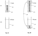
- Fig. 1 shows an elevator installation 10 in a simplified representation.
- elevator systems are known under the term multi-mobile elevator systems.
- the elevator installation 10 has an elevator shaft 11 in which an upper elevator car DU and a lower elevator car LU can move vertically.
- the upper elevator car DU serves a zone B, which extends from the uppermost stop 13.n of the elevator system 10 to a lower stop 13.2, which extends above the lowest stop 13.1 of the lower elevator car LU is located.
- the lower elevator car LU serves a zone A which extends from an upper stop 13.n-1, which is below the uppermost stop 13.n of the upper elevator car DU, to the lowest stop 13.1 of the elevator system 10. If, for example, the elevator shaft 11 is 100 floors high, the upper elevator car DU covers floors 1 - 100 and the lower elevator car LU covers floors 0 - 99.
- the elevator cars DU and LU can move independently of one another in the elevator shaft 11.
- the upper elevator car DU has a first drive and brake system which comprises a first holding brake (preferably a motor brake).
- the lower elevator cage LU has a second drive and brake system that detects a second holding brake (preferably a motor brake).
- the drives are, for example, traction sheave drives with traction sheaves which connect the elevator cars DU, LU to counterweights via conveying means. For the sake of clarity, neither the drives nor the funding and counterweights are in the Fig. 1 shown.
- the elevator installation 10 also preferably has a collision protection system in order to prevent the two elevator cars DU and LU from colliding.
- the elevator system 10 advantageously organizes the transport of the passengers with what is known as a destination call control.
- the elevator car is called from a location in the building (e.g. in the lobby in front of an elevator shaft) where a passenger is located by entering a destination.
- Such destination calls are entered by the passengers using a destination call input device.
- a destination call contains at least one piece of information about the location of the destination input and at least one piece of information about the desired destination.
- the destination call input devices transfer destination call information to the elevator control or to another elevator component which stores and / or processes the incoming destination calls.
- the elevator control includes at least information about the desired destination, in particular a floor or floor group, and about the location of the building where the passenger is located (e.g. the floor).
- the destination call control differs significantly from a conventional car call control, which does not have any information about the destination of the passenger when the car is called.
- the destination is entered in the elevator car, that is to say after the elevator car has been assigned to a car call.
- the destination call input devices can be permanently installed panels on floors 13.1 to 13.n at entrances 14.n to the elevator system 10, for example with a 10-key keypad and / or touch screen, but they can also be mobile devices carried by the passengers, such as cell phones, cards with RF-ID means, or the like.
- An elevator controller 20 which is shown in Fig. 1 is shown in a highly schematic manner, receives information (called destination call information) about the location of the destination call input devices Destination call entry and the destination.
- This destination call information is in Fig. 1 represented by arrows pointing to the elevator control 20. These arrows are labeled according to the following scheme.
- a destination call which indicates that a passenger wants to reach the lowest floor 13.1 (lowest stop) is denoted by a Z.1.
- Z.2 is a destination call for the 2nd lowest floor 13.2
- Zn-1 is a destination call for the floor 13.n-1
- Zn is a destination call for the top floor 13.n (top stop).
- the elevator control 20 also receives information which indicates the current location (e.g. the floor) where the corresponding passenger is located.
- This destination call information can be used at any point in time to optimize the transport capacity of the elevator system 10, as is described below with reference to various embodiments.
- the target call information is used to determine how many passengers have currently placed a target call, for example in order to reach the lowest stop 13.1 of the building and where in the building these passengers are located.
- the lower elevator car LU is used in the normal mode to transport passengers to the lowest stop 13.1, since this stop 13.1 cannot be reached through the upper elevator car DU. If the elevator control 20 determines that more destination calls z.1 for the lowest stop have been received than the lower elevator car LU is able to convey at the given time without letting the passengers wait too long, the elevator system 10 switches to one so-called downward replacement mode. In this downward substitute mode, the upper elevator car DU is used as a supplement / support for the transport of passengers who want to go to the lowest stop 13.1.
- the upper elevator car DU is provided on the corresponding floors and the passengers are allowed to board. Only after the passengers have entered the upper elevator car DU, or when it has started moving, the passengers are informed that this elevator car DU only travels to a stop 13.2, which is, for example, one floor above the lowest stop 13.1. After leaving the elevator car DU, the passengers can then cover the rest of the downward path to the lowest floor 13.1, e.g. via an (escalator) staircase. In an alternative embodiment, the passengers are informed that this elevator car DU only travels up to a stop 13.n-1 to 13.2 in the zone used by the two elevator cars DU, LU. The passengers leave the elevator car DU on this floor and wait until the lower elevator car DU stops in order to bring the passengers to the lowest floor 13.1. The floor 13.n-1 to 13.2 approached by the upper elevator car DU thus serves as a transfer floor.
- the downward capacity of the elevator system 10 can be increased significantly, since the passengers who want to get to the lowest stop 13.1 at the same moment are no longer dependent only on the lower elevator car LU.
- this downward replacement mode is used in particular temporarily and when there is a particular need.
- the automatic transition from the normal mode to the downward substitute mode can be triggered when one or more conditions (called the trigger condition) are met.
- a traffic-dependent elevator control 20 is based on the destination calls z.1-Zn determines whether the number of destination calls z.1 from passengers who want to reach the lowest stop 13.1 is greater than a downward transport limit LUmax of the lower elevator car LU. If this is the case, the elevator system 10 changes over to the downward substitute mode.
- the downward conveyance limit LUmax of the lower elevator car LU is used as a trigger condition.
- the destination calls z.1 - Z.n that were placed by passengers are recorded.
- the elevator control 20 triggers the change from the normal mode to the downward replacement mode.
- an automatic elevator control 20 it is determined on the basis of previously specified information whether the elevator installation 10 should switch to the downward replacement mode.
- the elevator system 10 can be programmed in such a way that in the afternoons between 4 p.m. and 4:30 p.m. (called the release time), the system 10 is always operated in downward substitute mode, since a large number of passengers want to leave the building at this time.
- the downward substitute mode can also be switched on in emergency situations. If, for example, the building has to be evacuated, the conveying capacity can be increased significantly.
- a comes in addition to or as an alternative to the downward substitute mode so-called upward replacement mode is used.
- the elevator installation can 1.) be operated in normal mode or in upward substitute mode, 2.) in normal mode or in downward substitute mode or 3.) in normal mode or in downward and upward substitute mode.
- this upward replacement mode is used in particular temporarily and when there is a particular need.
- the automatic transition from normal mode to upward substitute mode can be triggered when one or more conditions (called trigger condition) are met.
- the destination calls z.1-Zn are used to determine whether the number of destination calls Zn from passengers who want to reach the uppermost stop 13.n is greater than an upward transport limit DUmax of the upper elevator car DU. If this is the case, the elevator system 10 changes over to the upward substitute mode.
- the third embodiment by comparing the upward transport limit DUmax with the target calls Z.n currently available for the top stop 13.n, it is determined whether the number of existing target calls Z.n is greater than the upward transport limit DUmax, in order to then switch to the upward replacement mode.
- an automatic elevator control 20 it is determined on the basis of previously specified information whether the elevator installation 10 should switch to the upward replacement mode.
- the elevator system 10 can be programmed for working days so that the system is always in the morning between 7 and 8 a.m. Upward substitute mode is operated, since at this time a large number of passengers enter the building.
- the elevator control 20 and / or the destination call system coordinates all the elevators LU, DU.
- the destination call control can be linked to the elevator control 20 using known and proven means.
- the actuation of the drives takes place on the part of the elevator control 20 by appropriate signals or other control variables, as in FIG Fig. 1 indicated by the arrows A1 and B1.
- the invention is preferably characterized in that nothing changes in the zone coverage of the individual elevator cars LU, DU.
- the provision of the respective elevator cars LU, DU takes place in such a way that an increased conveying capacity is achieved downwards and / or upwards in that passengers are made to use the less suitable elevator car, although this elevator car does not quite reach the desired destination.
- the method according to the invention obviously works best when the two elevator cars LU, DU look identical, so that the passengers cannot recognize when entering the elevator car LU, DU that this journey will not lead them completely to the destination entered in the destination call control .
- the elevator installation 10 can return to normal mode after what are known as reset conditions have been fulfilled.
- further limit values e.g. LUmin and / or DUmin, can be used here, and if they are not reached, the transition to normal mode takes place.
- a further time can be specified as a reset condition.
- the illustrated implementation example of the invention comprises a destination call system (not shown) which is linked to the elevator control 20 in the operating state.
- This link is designed in such a way that the elevator control 20 is able to receive the destination calls z.1-Zn from the destination call system and to send them to an evaluation.
- the elevator control 20 can comprise a software and / or hardware module 21 which contains the essential elements for the comparison operations.
- This software and / or hardware module 21 can, however, also be arranged elsewhere.
- the software and / or hardware module 21 can also comprise a temporary memory in which the incoming destination calls z.1-Zn are temporarily stored. This memory is then deleted after the passengers have been transported.
- So-called (shift) registers in which the destination calls are stored and processed in sequence are particularly suitable.
- the (sliding) register principle is in the Figures 2A and 2B Explained using two typical situations.
- the passengers are only informed after boarding or during the transport that the elevator car in which the passengers are currently located does not approach the desired destination, but only up to approaching this goal at a stop.
- the elevator cars DU, LU can be equipped with appropriate means in order to inform the passengers accordingly acoustically and / or visually.
- an announcement shortly before reaching the stop 13.2 can inform the passengers that they should leave the cabin DU on the 1st floor and use a staircase or escalator down to reach the lowest floor 13.1.
- further acoustic and / or visual means can be attached to guide the passengers disembarking on the 1st floor 13.2 to the lowest floor 13.1.
- assign For example, a signal can be sent to a stationary escalator so that the escalator begins to run shortly before the passengers on a replacement journey arrive.
- further acoustic and / or visual means can be installed in order to avoid the traffic on the transfer floor 13.n-1 to 13.2 to inform disembarking passengers when a lower elevator car LU is ready for a further journey to the lowest floor 13.1.
Description
Die Erfindung betrifft ein Verfahren zum Betreiben einer Aufzugsanlage mit zwei Aufzugskabinen, die im selben Aufzugsschacht angeordnet und voneinander unabhängig antreibbar sind, nach dem Oberbegriff des Anspruchs 1 und eine entsprechend betreibbare Aufzugsanlage nach dem Oberbegriff des Anspruchs 8.The invention relates to a method for operating an elevator system with two elevator cars, which are arranged in the same elevator shaft and can be driven independently of one another, according to the preamble of
Es gibt verschiedene Aufzugsanlagen, die mehrere Aufzugskabinen in einem Aufzugsschacht aufweisen. Aufzugsanlagen mit mehreren Aufzugskabinen im selben Schacht, die auch als Multimobil-Aufzugsanlagen bezeichnet werden, weisen üblicherweise je ein Antriebs- und Bremssystem pro Aufzugskabine auf.There are various elevator systems that have several elevator cars in one elevator shaft. Elevator systems with several elevator cars in the same shaft, which are also referred to as multi-mobile elevator systems, usually each have a drive and brake system for each elevator car.
Je nach Anordnung der Aufzugskabinen kann damit zum Beispiel ein sogenannter Zonenbetrieb realisiert werden, wo jede Aufzugskabine einer Zone zugeordnet ist und zwischen den Zonen ein Umsteigestockwerk zum Umsteigen von Passagieren zwischen den Aufzugskabinen verschiedener Zonen angeordnet ist. Aus der Patentanmeldung
Besonders in hohen Gebäuden tritt heute ein grosser Transportbedarf auf. Um diesen Transportbedarf zu befriedigen, kann, wie erwähnt, eine Multimobil-Aufzugsanlage installiert werden.Today, there is a great need for transport, especially in tall buildings. As mentioned, a multi-mobile elevator system can be installed in order to satisfy this transport requirement.
Probleme und Kapazitätsengpässe ergeben sich aber besonders zu den Spitzenzeiten, wo zum Beispiel Hunderte von Menschen morgens den Eingangsbereich eines Gebäudes betreten und höher gelegene Stockwerke erreichen wollen, oder am Feierabend, wo eine grosse Zahl von Personen zum untersten Stockwerk zu gelangen wünschen, um das Gebäude zu verlassen.Problems and capacity bottlenecks arise, however, especially at peak times, when, for example, hundreds of people enter the entrance area of a building in the morning and want to reach higher floors, or at the end of the day, when a large number of people want to get to the lowest floor in order to reach the building to leave.
Es gibt verschiedene Lösungen zur Erhöhung der Transportkapazität, um solche "Spitzenlasten" bewältigen zu können. So wird bspw. eine Erhöhung der Geschwindigkeit oder Beschleunigung der Aufzugskabinen oder eine Verkürzung der Türoffenzeiten angewendet. Meist sind Aufzüge bezüglich Motorleistung und Stromzuführung jedoch nicht überdimensioniert, so dass eine Erhöhung der Geschwindigkeit/Beschleunigung der Kabinen nur in sehr begrenztem Umfang in Betracht kommt. Weiter wirkt sich eine Erhöhung der Beschleunigung der Kabinen negativ auf das Fahrempfinden der Personen aus, so dass auch hier nur sehr begrenzt eine Erhöhung der Transportkapazität erreicht werden kann. Auch ist eine Verkürzung bzw. Optimierung der Türöffnungszeiten in vielen Aufzügen bereits standardmässig implementiert. Somit führen diese Massnahmen zu keiner wirklich spürbaren Erhöhung der Transportkapazität.There are various solutions for increasing the transport capacity in order to cope with such "peak loads". For example, an increase in the speed or acceleration of the elevator cars or a shortening of the door open times is used. In most cases, however, elevators are not oversized in terms of motor power and power supply, so that increasing the speed / acceleration of the cabins is only possible to a very limited extent. Furthermore, an increase in the acceleration of the cabs has a negative effect on the driving experience of the people, so that here too an increase in the transport capacity can only be achieved to a very limited extent. A shortening or optimization of the door opening times is already implemented as standard in many elevators. Thus, these measures do not lead to a really noticeable increase in transport capacity.
Selbstverständlich ist es auch möglich, die gesamte Aufzugsanlage in einem Gebäude so zu dimensionieren, dass sie in der Lage ist auch die "Spitzenlasten" zu bewältigen. Dies hat aber den Nachteil, dass diese Aufzugsanlagen quasi für den Normalbetrieb überdimensioniert sind. Einerseits sind solche überdimensionierten Aufzugsanlagen dann teuerer als notwendig und andererseits belegen sie einen relativ grossen Raumanteil des Gebäudes.Of course, it is also possible to dimension the entire elevator system in a building in such a way that it is also able to cope with the "peak loads". However, this has the disadvantage that these elevator systems are virtually oversized for normal operation. On the one hand, such oversized elevator systems are more expensive than necessary and, on the other hand, they occupy a relatively large proportion of the building's space.
Die
Aufgabe der Erfindung ist nun,
- ein Verfahren vorzuschlagen, um bei einer Multimobil-Aufzugsanlage eine Verbessung der Abwärts- und/oder Aufwärtsförderkapazität zu erreichen, ohne überdimensionierte Aufzugsanlagen vorzusehen;
- eine Multimobil-Aufzugsanlage zu schaffen, die gemäss diesem Verfahren betreibbar ist.
- to propose a method to improve the downward and / or upward conveying capacity of a multi-mobile elevator system without providing oversized elevator systems;
- to create a multi-mobile elevator system that can be operated according to this method.
Die Lösung der Aufgabe erfolgt
- für das Verfahren durch die Merkmale des
Anspruchs 1; und - für die Aufzugsanlage durch die Merkmale des Anspruchs 8.
- for the method by the features of
claim 1; and - for the elevator system by the features of claim 8.
Vorteilhafte Ausführungsbeispiele und Weiterbildungen der Erfindung sind durch die jeweiligen abhängigen Patentansprüche umschrieben.Advantageous exemplary embodiments and developments of the invention are described by the respective dependent claims.
Die neue Aufzugsanlage weist mindestens eine obere Aufzugskabine und eine untere Aufzugskabine auf. Die beiden Aufzugskabinen können sich vorzugsweise, im Wesentlichen unabhängig voneinander, in einem gemeinsamen Aufzugsschacht der Aufzugsanlage vertikal auf- und abwärts bewegen.The new elevator system has at least one upper elevator car and one lower elevator car. The two elevator cars can preferably move vertically up and down in a common elevator shaft of the elevator installation, essentially independently of one another.
Aufgrund der Anordnung der beiden Aufzugskabinen ergeben sich überlappende Zonen. Die obere Aufzugskabine bedient eine Zone, die sich vom obersten Halt der Aufzugsanlage bis zu einem unteren Halt erstreckt, der sich oberhalb des untersten Halts der unteren Aufzugskabine befindet. Die untere Aufzugskabine hingegen bedient vorzugsweise eine Zone, die sich von einem oberen Halt, der unterhalb des obersten Halts der oberen Aufzugskabine liegt, bis zu dem untersten Halt der Aufzugsanlage erstreckt.The arrangement of the two elevator cars results in overlapping zones. The upper elevator car serves a zone which extends from the uppermost stop of the elevator installation to a lower stop which is located above the lowest stop of the lower elevator car. The lower elevator car however, preferably serves a zone which extends from an upper stop, which is below the uppermost stop of the upper elevator car, to the lowest stop of the elevator installation.
Die Erfindung zeichnet sich nun insbesondere dadurch aus, dass die entsprechende Aufzugsanlage in einem Normalmodus und in einem Ersatzmodus, z.B. einem Abwärtsersatzmodus und/oder einem Aufwärtsersatzmodus, betrieben werden kann. In dem Normalmodus wird primär die untere Aufzugskabine für die Passagiere bereitgestellt, die mittels Zielruf angezeigt haben, dass sie den untersten Halt bzw. das unterste Stockwerk erreichen möchten. Im Abwärtsersatzmodus hingegen wird zusätzlich die obere Aufzugskabine für Passagiere eingesetzt, die den untersten Halt bzw. das unterste Stockwerk erreichen möchten. Diese Passagiere werden dann in der oberen Aufzugskabine befördert, wobei erst während des Beförderns den Passagieren zur Kenntnis gebracht wird, dass diese Aufzugskabine im Moment einen Halt oberhalb des untersten Halts bzw. des untersten Stockwerks anfährt.The invention is now particularly characterized in that the corresponding elevator installation can be operated in a normal mode and in a substitute mode, e.g. a downward substitute mode and / or an upward substitute mode. In the normal mode, the lower elevator car is primarily provided for the passengers who have indicated by means of a destination call that they want to reach the lowest stop or the lowest floor. In the downward substitute mode, however, the upper elevator car is also used for passengers who want to reach the lowest stop or the lowest floor. These passengers are then transported in the upper elevator car, the passengers only being informed during the transportation that this elevator car is currently approaching a stop above the lowest stop or the lowest floor.
Im optionalen Aufwärtsersatzmodus hingegen wird die untere Aufzugskabine für Passagiere eingesetzt, die den obersten Halt bzw. das oberste Stockwerk erreichen möchten. Diese Passagiere werden dann in der unteren Aufzugskabine befördert, wobei erst während des Beförderns den Passagieren zur Kenntnis gebracht wird, dass diese Aufzugskabine im Moment einen Halt unterhalb des obersten Halts bzw. das obersten Stockwerks anfährt.In the optional upward substitute mode, however, the lower elevator car is used for passengers who want to reach the top stop or the top floor. These passengers are then transported in the lower elevator car, the passengers only being informed during the transportation that this elevator car is currently approaching a stop below the uppermost stop or the uppermost floor.
Um zu ermitteln, ob ein Übergang von dem Normalmodus in einen Ersatzmodus erfolgen soll, wird geprüft, ob mindestens eine Auslösebedingung erfüllt ist.In order to determine whether a transition from the normal mode to a substitute mode should take place, a check is made as to whether at least one trigger condition is met.
Weitere Einzelheiten und Vorteile der Erfindung werden im Folgenden an Hand eines Ausführungsbeispiels und mit Bezug auf die Zeichnung beschrieben. Es zeigen:
- Fig. 1
- eine Multimobil-Aufzugsanlage gemäss Erfindung, in einer stark vereinfachten, schematisierten Darstellung;
- Fig. 2A
- eine schematische Darstellung einer Situation, wo die Anzahl der Zielrufe für Fahrten zum untersten Halt kleiner ist als eine Abwärtsbeförderungsgrenze LUmax;
- Fig. 2B
- eine schematische Darstellung einer Situation, wo die Anzahl der Zielrufe für Fahrten zum untersten Halt grösser ist als die Abwärtsbeförderungsgrenze LUmax.
- Fig. 1
- a multi-mobile elevator system according to the invention, in a greatly simplified, schematic representation;
- Figure 2A
- a schematic representation of a situation where the number of destination calls for trips to the lowest stop is less than a downward movement limit LUmax;
- Figure 2B
- a schematic representation of a situation where the number of destination calls for trips to the lowest stop is greater than the downward transport limit LUmax.
Aufgrund der Anordnung der beiden Aufzugskabinen LU und DU ergeben sich beispielsweise überlappende Zonen A und B. Die obere Aufzugskabine DU bedient eine Zone B, die sich vom obersten Halt 13.n der Aufzugsanlage 10 bis zu einem unteren Halt 13.2 erstreckt, der sich oberhalb des untersten Halts 13.1 der unteren Aufzugskabine LU befindet. Die untere Aufzugskabine LU hingegen bedient eine Zone A, die sich von einem oberen Halt 13.n-1, der unterhalb des obersten Halts 13.n der oberen Aufzugskabine DU liegt, bis zu dem untersten Halt 13.1 der Aufzugsanlage 10 erstreckt. Falls der Aufzugsschacht 11 z.B. insgesamt 100 Stockwerke hoch ist, so deckt die obere Aufzugskabine DU die Stockwerke 1 - 100 und die untere Aufzugskabine LU die Stockwerke 0 - 99 ab.Due to the arrangement of the two elevator cars LU and DU, for example, overlapping zones A and B. The upper elevator car DU serves a zone B, which extends from the uppermost stop 13.n of the
Solange eine kritische Minimaldistanz zwischen den beiden Aufzugskabinen DU und LU eingehalten wird, können sich die Aufzugskabinen DU und LU unabhängig voneinander im Aufzugsschacht 11 bewegen.As long as a critical minimum distance is maintained between the two elevator cars DU and LU, the elevator cars DU and LU can move independently of one another in the
Die obere Aufzugskabine DU weist ein erstes Antriebs- und Bremssystem auf, das eine erste Haltebremse (vorzugsweise eine Motorbremse) umfasst. Die untere Aufzugskabine LU weist ein zweites Antriebs- und Bremssystem auf, das eine zweite Haltebremse (vorzugsweise eine Motorbremse) und erfasst. Bei den Antrieben handelt es sich bspw. um Treibscheibenantriebe mit Treibscheiben, welche die Aufzugskabinen DU, LU über Fördermittel mit Gegengewichten verbinden. Aus Gründen der Übersichtlichkeit sind weder die Antriebe noch die Fördermittel und Gegengewichte in der
Die Aufzugsanlage 10 weist ausserdem vorzugsweise ein Auffahr-Schutzsystem auf, um ein Auffahren der beiden Aufzugskabinen DU und LU zu verhindern.The
Vorteilhafterweise organisiert die Aufzugsanlage 10 den Transport der Passagiere mit einer sogenannten Zielrufsteuerung. Dabei erfolgt von einem Ort des Gebäudes (z.B. in der Lobby vor einem Aufzugsschacht) aus, an dem sich ein Passagier befindet, ein Ruf der Aufzugskabine mittels Eingabe eines Ziels. Derartige Zielrufe werden durch die Passagiere mittels eines Zielrufeingabegeräts eingegeben. Ein Zielruf beinhaltet dabei mindestens eine Information zum Standort der Zieleingabe und mindestens eine Information zum gewünschten Ziel. Die Zielrufeingabegeräte übergeben also Zielrufinformation an die Aufzugsteuerung oder an eine andere Aufzugskomponente, welche die eingehenden Zielrufe speichert und/oder weiterverarbeitet. Die Aufzugssteuerung umfasst beim Ruf der Kabine mindestens Angaben über das gewünschte Fahrziel insbesondere einem Stockwerk oder Stockwerkgruppe und über den Ort des Gebäudes, wo sich der Passagier befindet (z.B. das Stockwerk). Insbesondere wird erfasst, welches Zieleingabegerät durch den Passagier betätigt wurde. Dadurch unterscheidet sich die Zielrufsteuerung wesentlich von einer herkömmlichen Kabinenrufsteuerung, die beim Ruf der Kabine keinerlei Angaben zum Ziel des Passagiers verfügt. Bei einer solch herkömmlichen Steuerung erfolgt die Eingabe des Ziels in der Aufzugskabine, also nach der Zuteilung der Aufzugskabine zu einem Kabinenruf durch.The
Aus Gründen der Übersichtlichkeit sind in der
Eine Aufzugssteuerung 20, die in
Wie bereits ausgeführt, geht neben der Zielinformation auch Information bei der Aufzugssteuerung 20 ein, welche den gegenwärtige Standort (z.B. das Stockwerk) angibt, wo sich der entsprechende Passagier befindet.As already stated, in addition to the destination information, the
Diese Zielrufinformationen lassen sich zu jedem Zeitpunkt zur Optimierung der Transportkapazität der Aufzugsanlage 10 nutzen, wie im Folgenden anhand verschiedener Ausführungsformen beschrieben wird.This destination call information can be used at any point in time to optimize the transport capacity of the
So wird aus den Zielrufinformationen ermittelt, wie viele Passagiere gegenwärtig einen Zielruf platziert haben, um zum Beispiel den untersten Halt 13.1 des Gebäudes zu erreichen und wo im Gebäude sich diese Passagiere befinden. Gemäss Erfindung wird im Normalmodus die untere Aufzugskabine LU eingesetzt, um Passagiere zum untersten Halt 13.1 zu befördern, da dieser Halt 13.1 durch die obere Aufzugskabine DU nicht erreichbar ist. Stellt die Aufzugssteuerung 20 fest, dass mehr Zielrufe z.1 für den untersten Halt eingegangen sind, als die untere Aufzugskabine LU im gegebenen Zeitpunkt zu befördern in der Lage ist, ohne die Passagiere zu lange warten zu lassen, so geht die Aufzugsanlage 10 in einen sogenannten Abwärtsersatzmodus über. In diesem Abwärtsersatzmodus wird ergänzend/unterstützend die obere Aufzugskabine DU für den Transport von Passagieren eingesetzt, die zum untersten Halt 13.1 möchten.The target call information is used to determine how many passengers have currently placed a target call, for example in order to reach the lowest stop 13.1 of the building and where in the building these passengers are located. According to the invention, the lower elevator car LU is used in the normal mode to transport passengers to the lowest stop 13.1, since this stop 13.1 cannot be reached through the upper elevator car DU. If the
Zu diesem Zweck wird die obere Aufzugskabine DU an den entsprechenden Stockwerken bereitgestellt und den Passagieren wird das Einsteigen ermöglicht. Erst nachdem die Passagiere die obere Aufzugskabine DU betreten haben, oder wenn diese sich in Bewegung gesetzt hat, werden die Passagiere darauf hingewiesen, dass diese Aufzugskabine DU nur bis zu einem Halt 13.2 fährt, der beispielsweise ein Stockwerk über dem untersten Halt 13.1 liegt. Nach dem Verlassen der Aufzugskabine DU können die Passagiere dann den Rest des Abwärtsweges zum untersten Stockwerk 13.1 z.B. über eine (Roll-)Treppe zurück legen. In einer alternativen Ausführungsform werden die Passagiere darauf hingewiesen, dass diese Aufzugskabine DU nur bis zu einem Halt 13.n-1 bis 13.2 in der von beiden Aufzugskabinen DU, LU befahrenen Zone fährt. Die Passagiere verlassen die Aufzugskabine DU auf diesem Stockwerk und warten bis die untere Aufzugskabine DU anhält, um die Passagiere bis ins unterste Stockwerk 13.1 zu bringen. Das von der oberen Aufzugskabine DU angefahrene Stockwerk 13.n-1 bis 13.2 dient also als Umsteigestockwerk.For this purpose, the upper elevator car DU is provided on the corresponding floors and the passengers are allowed to board. Only after the passengers have entered the upper elevator car DU, or when it has started moving, the passengers are informed that this elevator car DU only travels to a stop 13.2, which is, for example, one floor above the lowest stop 13.1. After leaving the elevator car DU, the passengers can then cover the rest of the downward path to the lowest floor 13.1, e.g. via an (escalator) staircase. In an alternative embodiment, the passengers are informed that this elevator car DU only travels up to a stop 13.n-1 to 13.2 in the zone used by the two elevator cars DU, LU. The passengers leave the elevator car DU on this floor and wait until the lower elevator car DU stops in order to bring the passengers to the lowest floor 13.1. The floor 13.n-1 to 13.2 approached by the upper elevator car DU thus serves as a transfer floor.
Durch diese steuerungstechnische Massnahme, kann die Abwärtskapazität der Aufzugsanlage 10 deutlich erhöht werden, da die Passagiere, die im gleichen Moment zum untersten Halt 13.1 gelangen möchten, nicht mehr nur auf die untere Aufzugskabine LU angewiesen sind.By means of this control measure, the downward capacity of the
Gemäss Erfindung wird dieser Abwärtsersatzmodus insbesondere temporär und bei besonderem Bedarf eingesetzt. Dabei kann gemäss Erfindung der automatische Übergang vom Normalmodus in den Abwärtsersatzmodus ausgelöst werden, wenn eine oder mehrere Bedingungen (Auslösebedingung genannt) erfüllt sind.According to the invention, this downward replacement mode is used in particular temporarily and when there is a particular need. According to the invention, the automatic transition from the normal mode to the downward substitute mode can be triggered when one or more conditions (called the trigger condition) are met.
Bei einer ersten Ausführungsform der Erfindung, bei welcher eine verkehrsabhängige Aufzugsteuerung 20 vorgesehen ist, wird anhand der Zielrufe z.1 - Z.n ermittelt, ob die Anzahl der Zielrufe z.1 von Passagieren, die den untersten Halt 13.1 erreichen möchten, grösser ist als eine Abwärtsbeförderungsgrenze LUmax der unteren Aufzugskabine LU. Falls dies zutrifft, geht die Aufzugsanlage 10 in den Abwärtsersatzmodus über.In a first embodiment of the invention, in which a traffic-
Bei der ersten Ausführungsform wird die Abwärtsbeförderungsgrenze LUmax der unteren Aufzugskabine LU als Auslösebedingung eingesetzt. Es werden die Zielrufe z.1 - Z.n erfasst, die von Passagieren abgesetzt wurden. Dann wird durch einen Vergleich der Abwärtsbeförderungsgrenze LUmax mit den gegenwärtig für den untersten Halt 13.1 vorliegenden Zielrufen z.1 geprüft, ob die Anzahl der Zielrufe z.1 von Passagieren, die den untersten Halt 13.1 erreichen möchten, grösser ist als die Abwärtsbeförderungsgrenze LUmax. Dann löst die Aufzugssteuerung 20 den Wechsel vom Normalmodus zum Abwärtsersatzmodus aus.In the first embodiment, the downward conveyance limit LUmax of the lower elevator car LU is used as a trigger condition. The destination calls z.1 - Z.n that were placed by passengers are recorded. Then, by comparing the downward transport limit LUmax with the target calls z.1 currently available for the lowest stop 13.1, it is checked whether the number of target calls z.1 from passengers who want to reach the lowest stop 13.1 is greater than the downward transport limit LUmax. Then the
Bei einer zweiten Ausführungsform der Erfindung, bei welcher eine automatische Aufzugsteuerung 20 vorgesehen ist, wird anhand vorher festgelegter Information ermittelt, ob die Aufzugsanlage 10 in den Abwärtsersatzmodus übergehen soll. Es kann zum Beispiel für Werktage die Aufzugsanlage 10 so programmiert sein, dass nachmittags zwischen 16 und 16:30 Uhr (Auslösezeit genannt) die Anlage 10 stets im Abwärtsersatzmodus betrieben wird, da in diesem Zeitpunkt eine grosse Anzahl von Passagieren das Gebäude zu verlassen wünschen.In a second embodiment of the invention, in which an
Zusätzlich oder alternativ zu dieser zeitabhängigen Auslegung der Erfindung kann auch der Abwärtsersatzmodus in Notsituationen eingeschaltet werden. Wenn zum Beispiel das Gebäude evakuiert werden muss, kann somit die Förderkapazität deutlich erhöht werden.In addition or as an alternative to this time-dependent configuration of the invention, the downward substitute mode can also be switched on in emergency situations. If, for example, the building has to be evacuated, the conveying capacity can be increased significantly.
Bei einer weiteren Ausführungsform der Erfindung kommt zusätzlich oder alternativ zu dem Abwärtsersatzmodus ein sogenannter Aufwärtsersatzmodus zum Einsatz. In diesem Fall kann die Aufzugsanlage 1.) im Normalmodus oder im Aufwärtsersatzmodus, 2.) im Normalmodus oder im Abwärtsersatzmodus oder 3.) im Normalmodus oder im Abwärts- und Aufwärtsersatzmodus betrieben werden.In a further embodiment of the invention, a comes in addition to or as an alternative to the downward substitute mode so-called upward replacement mode is used. In this case the elevator installation can 1.) be operated in normal mode or in upward substitute mode, 2.) in normal mode or in downward substitute mode or 3.) in normal mode or in downward and upward substitute mode.
Gemäss Erfindung wird dieser Aufwärtsersatzmodus insbesondere temporär und bei besonderem Bedarf eingesetzt. Dabei kann gemäss Erfindung der automatische Übergang vom Normalmodus in den Aufwärtsersatzmodus ausgelöst werden, wenn eine oder mehrere Bedingungen (Auslösebedingung genannt) erfüllt sind.According to the invention, this upward replacement mode is used in particular temporarily and when there is a particular need. According to the invention, the automatic transition from normal mode to upward substitute mode can be triggered when one or more conditions (called trigger condition) are met.
Bei einer dritten Ausführungsform der Erfindung, bei welcher eine verkehrsabhängige Aufzugsteuerung vorgesehen ist, wird anhand der Zielrufe z.1 - Z.n ermittelt, ob die Anzahl der Zielrufe Z.n von Passagieren, die den obersten Halt 13.n erreichen möchten, grösser ist als eine Aufwärtsbeförderungsgrenze DUmax der oberen Aufzugskabine DU. Falls dies zutrifft, geht die Aufzugsanlage 10 in den Aufwärtsersatzmodus über.In a third embodiment of the invention, in which a traffic-dependent elevator control is provided, the destination calls z.1-Zn are used to determine whether the number of destination calls Zn from passengers who want to reach the uppermost stop 13.n is greater than an upward transport limit DUmax of the upper elevator car DU. If this is the case, the
Bei der dritten Ausführungsform wird durch einen Vergleich der Aufwärtsbeförderungsgrenze DUmax mit den gegenwärtig für den obersten Halt 13.n vorliegenden Zielrufen Z.n ermittelt, ob die Anzahl der vorliegenden Zielrufe Z.n grösser ist als die Aufwärtsbeförderungsgrenze DUmax, um dann in den Aufwärtsersatzmodus zu wechseln.In the third embodiment, by comparing the upward transport limit DUmax with the target calls Z.n currently available for the top stop 13.n, it is determined whether the number of existing target calls Z.n is greater than the upward transport limit DUmax, in order to then switch to the upward replacement mode.
Bei der vierten Ausführungsform der Erfindung, bei welcher eine automatische Aufzugsteuerung 20 vorgesehen ist, wird anhand vorher festgelegter Information ermittelt, ob die Aufzugsanlage 10 in den Aufwärtsersatzmodus übergehen soll. Es kann zum Beispiel für Werktage die Aufzugsanlage 10 so programmiert werden, dass morgens zwischen 7 und 8 Uhr die Anlage stets im Aufwärtsersatzmodus betrieben wird, da in diesem Zeitpunkt eine grosse Anzahl von Passagieren das Gebäude betritt.In the fourth embodiment of the invention, in which an
Gemäss Erfindung koordiniert die Aufzugssteuerung 20 und/oder die Zielrufanlage alle Aufzüge LU, DU. Hierzu ist die Zielrufsteuerung über bekannte und bewährte Mittel mit der Aufzugssteuerung 20 verknüpfbar. Die Ansteuerung der Antriebe erfolgt seitens der Aufzugssteuerung 20 durch entsprechende Signale oder andere Steuergrössen, wie in
Die Erfindung zeichnet sich vorzugsweise dadurch aus, dass sich nichts an der Zonenabdeckung der einzelnen Aufzugskabinen LU, DU ändert. Die Bereitstellung der jeweiligen Aufzugskabinen LU, DU erfolgt hingegen so, dass abwärts und/oder aufwärts eine erhöhte Förderkapazität erreicht wird, indem Passagiere dazu gebracht werden die weniger geeignete Aufzugskabine zu benutzen, obwohl diese Aufzugskabine das gewünscht Ziel nicht ganz erreicht.
Das erfindungsgemässe Verfahren funktioniert offensichtlich dann am besten, wenn die beiden Aufzugskabinen LU, DU identisch aussehen, damit die Passagiere im Moment des Betretens der Aufzugskabine LU, DU nicht erkennen können, dass diese Fahrt sie nicht ganz zu dem in die Zielrufsteuerung eingegebenen Ziel führen wird.The invention is preferably characterized in that nothing changes in the zone coverage of the individual elevator cars LU, DU. The provision of the respective elevator cars LU, DU, however, takes place in such a way that an increased conveying capacity is achieved downwards and / or upwards in that passengers are made to use the less suitable elevator car, although this elevator car does not quite reach the desired destination.
The method according to the invention obviously works best when the two elevator cars LU, DU look identical, so that the passengers cannot recognize when entering the elevator car LU, DU that this journey will not lead them completely to the destination entered in the destination call control .
Je nach Implementierung der Erfindung kann die Aufzugsanlage 10 nach dem Erfüllen von sogenannten Rücksetzbedingungen in den Normalmodus zurückkehren. Bei den verkehrsabhängigen Ausführungsformen können hier weitere Grenzwerte, z.B. LUmin und/oder DUmin, eingesetzt werden, bei deren Unterschreiten der Übergang in den Normalmodus erfolgt.Depending on the implementation of the invention, the
Bei den zeitabhängig arbeitenden Ausführungsformen, kann als Rücksetzbedingung eine weitere Zeit vorgegeben werden.In the case of the time-dependent embodiments, a further time can be specified as a reset condition.
Das in
In
Das (Schiebe-)Register-Prinzip ist in den
The (sliding) register principle is in the
In
Wenn sich die Aufzugsanlage 10 im erfindungsgemässen Abwärts- oder Aufwärtsersatzmodus befindet, wird den Passagieren erst nach dem Einsteigen oder während des Beförderns zur Kenntnis gebracht, dass die Aufzugskabine, in der sich die Passagiere momentan befinden, nicht das gewünschte Ziel anfährt, sondern sich nur bis auf einen Halt diesem Ziel nähert. Die Aufzugskabinen DU, LU können mit entsprechenden Mitteln ausgestattet sein, um akustisch und/oder visuell die Passagiere entsprechend zu informieren.If the
So kann zum Beispiel im Fall des Abwärtsersatzmodus eine Durchsage kurz vor Erreichen des Halts 13.2 die Passagiere darauf hinweisen, dass sie zum Erreichen des untersten Stockwerks 13.1 die Kabine DU im 1. Stockwerk verlassen und eine Treppe oder Rolltreppe abwärts benutzen sollen. Im Bereich vor dem entsprechenden Aufzugsschacht 11 können weitere akustische und/oder visuelle Mittel angebracht sein, um den auf dem 1. Stockwerk 13.2 aussteigenden Passagieren den Weg in das unterste Stockwerk 13.1. zu weisen. Es kann zum Beispiel ein Signal an eine ruhende Rolltreppe geschickt werden, damit diese Rolltreppe zu laufen beginnt, kurz bevor die Passagiere einer Ersatzfahrt eintreffen.For example, in the case of the downward alternative mode, an announcement shortly before reaching the stop 13.2 can inform the passengers that they should leave the cabin DU on the 1st floor and use a staircase or escalator down to reach the lowest floor 13.1. In the area in front of the
In einer alternativen Ausführungsform weist eine Durchsage kurz vor Erreichen eines Halts 13.n-1 bis 13.2 im gemeinsamen Fahrbereich der oberen und unteren Aufzugskabinen DU, LU die Passagiere darauf hin, dass sie zum Erreichen des untersten Stockwerks 13.1 die Kabine DU auf dem angefahrenen Stockwerk 13.n-1 bis 13.2 verlassen und in eine untere Aufzugskabine LU umsteigen sollen. Im Bereich vor dem entsprechenden Aufzugsschacht 11 können weitere akustische und/oder visuelle Mittel angebracht sein, um den auf dem Umsteigestockwerk 13.n-1 bis 13.2 aussteigenden Passagieren mitzuteilen, wann eine untere Aufzugskabine LU für eine Weiterfahrt in das unterste Stockwerk 13.1 bereit steht.In an alternative embodiment, an announcement shortly before reaching a stop 13.n-1 to 13.2 in the common travel area of the upper and lower elevator cars DU, LU informs the passengers that they need the car DU on the floor approached to reach the lowest floor 13.1 13. Leave n-1 to 13.2 and change to a lower elevator car LU. In the area in front of the
Analoges gilt hinsichtlich der Benützung einerTreppe oder Rolltreppe ausgehend von einem obersten durch die untere Aufzugskabine LU zu bedienenden Stockwerk 13.n-1 in ein darüberliegendes Stockwerk 13.n auch für die Aufwärtsersatzfahrt. Zudem trifft zuvor Beschriebenes sinngemäss auch im Fall der Aufwärtsersatzfahrt bezüglich des Umsteigens von einer unteren Aufzugskabine LU in eine obere Aufzugskabine DU auf einem Umsteigestockwerk 13.2 bis 13.n-1 des gemeinsamen Fahrbereichs der beiden Aufzugskabinen LU, DU zu. Schliesslich sind auch hier analog zur Abwärtsersatzfahrt akustische und/oder visuelle Mittel einsetzbarThe same applies to the use of a staircase or escalator, starting from an uppermost floor 13.n-1 to be served by the lower elevator car LU to a floor 13.n above, also for the upward substitute journey. In addition, what has been described above also applies in the case of the upward substitute trip with regard to changing from a lower elevator car LU to an upper elevator car DU on a transfer floor 13.2 to 13.n-1 of the common travel area of the two elevator cars LU, DU. Finally, acoustic and / or visual means can also be used here analogously to the downward substitute travel
Dem Fachmann steht es bei Kenntnis der vorliegenden Erfindung frei, mehr oder weniger Aufzüge für den erfindungsgemässen Betrieb im Gebäude zu verwenden.With knowledge of the present invention, the person skilled in the art is free to use more or fewer elevators for the operation according to the invention in the building.
Claims (12)
- Method for operating an elevator system (10) which comprises at least an upper elevator car (DU) and a lower elevator car (LU) that are arranged in the same elevator shaft (11), characterized by the following steps:a1) operating the elevator system (10) in a normal mode, in the normal mode,the lower elevator car (LU) being provided for the passengers who have indicated by means of a destination call (Z.1) that they want to reach the lowermost floor (13.1),b1) checking whether at least one trigger condition is satisfied, and if this is the case, then switching to a downward alternative mode in order to temporarily provide the upper elevator car (DU) for passengers who want to reach the lowermost floor (13.1), and transporting these passengers in the upper elevator car (DU) to a floor (13.2 to 13.n-1) above the lowermost floor (13.1) and/ora2) operating the elevator system (10) in a normal mode, in the normal mode the upper elevator car (DU) being provided for the passengers who have indicated by means of a destination call (Z.n) that they want to reach the uppermost floor (13.n),b2) checking whether at least one trigger condition is satisfied, and if this is the case, then switching to an upward alternative mode in order to temporarily provide the lower elevator car (DU) for passengers who want to reach the uppermost floor (13.n), and transporting these passengers in the lower elevator car (LU) to a floor (13.2 to 13.n-1) below the uppermost floor (13.n).
- Method according to claim 1, characterized in that said method is a traffic-dependent method in which a downward transportation limit (LUmax) of the lower elevator car (LU) and/or an upward transportation limit (DUmax) of the upper elevator car (DU) is used as the trigger condition, the method comprising the following sub-steps:- detecting a plurality of destination calls (Z. 1-Z.n) from passengers,- by comparing the downward transportation limit (LUmax) with the current destination calls (Z.1) for the lowermost floor (13.1), checking whether the number of destination calls (Z.1) from passengers who want to reach the lowermost floor is greater than the downward transportation limit (LUmax) and/or- by comparing the upward transportation limit (DUmax) with the current destination calls (Z.n) for the uppermost floor (13.n), checking whether the number of destination calls (Z.n) from passengers who want to reach the uppermost floor is greater than the upward transportation limit (DUmax).
- Method according to claim 1, characterized in that the elevator system (10) automatically changes from the normal mode to the downward alternative mode when a trigger time is reached.
- Method according to claim 1, 2 or 3, characterized in that in the downward alternative mode the upper elevator car (DU) is used to assist the lower elevator car (LU) and the passengers are informed only during the transportation in the upper elevator car (DU) that the downward travel ends on the floor (13.2 to 13.n-1) above the lowermost floor (13.1) and/or
in the upward alternative mode the lower elevator car (LU) is used to assist the upper elevator car (DU) and the passengers are informed only during the transportation in the lower elevator car (LU) that the upward travel ends on the floor (13.2 to 13.n-1) below the uppermost floor (13.n). - Method according to any of the preceding claims, characterized in that the elevator system (10) automatically returns to the normal mode.
- Method according to any of claims 1-4, characterized in that the elevator system (10) returns to the normal mode after a reset condition has been satisfied.
- Method according to any of the preceding claims, characterized in that the comparison is carried out by central computing means (21) which receive destination call information (Z.1-Z.n) from the elevator system (10).
- Elevator system (10) comprising- an elevator shaft (11),- at least an upper elevator car (DU) and a lower elevator car (LU) that are arranged in the elevator shaft (11),- an elevator controller (20, 21), and- a destination call system which, in the operating state, is linked to the elevator controller (20, 21) such that the elevator controller (20, 21) is able to receive the destination calls (Z.1-Z.n) from the destination call system and to supply said calls to an evaluation means, characterized in that the elevator controller (20, 21) is configured such that the elevator system (10) can be operated in a normal mode and in an upward or downward alterative mode,by means of the elevator controller (20, 21):a1) in the normal mode, the lower elevator car (LU) being provided for passengers who want to reach the lowermost floor (13.1); andb1) in the downward alternative mode, it being possible to use the upper elevator car (DU) and the lower elevator car (LU) for downward travel, it being possible to fill the lower elevator car (LU) up to the downward transportation limit (LUmax) and to use the upper elevator car (DU) for passengers who want to reach the lowermost floor (13.1), in the downward alternative mode the lower elevator car (LU) approaching the lowermost floor (13.1) and the upper elevator car (DU) approaching a floor (13.2 to 13.n-1) above the lowermost floor (13.1); and/ora2) in normal mode, the upper elevator car (LU) being provided for passengers who want to reach the uppermost floor (13.n); andb2) in the upward alternative mode, it being possible to use the lower elevator car (LU) and the upper elevator car (DU) for upward travel, it being possible to fill the upper elevator car (DU) up to the upward transportation limit (DUmax) and to use the lower elevator car (LU) for passengers who want to reach the uppermost floor (13.n), in the upward alternative mode the upper elevator car (DU) approaching the uppermost floor (13.n) and the lower elevator car (LU) approaching a floor (13.2 to 13.n-1) below the uppermost floor (13.n).
- Elevator system (10) according to claim 8, characterized in that the destination call system of the elevator controller (20, 21) transmits destination call information that transmits information about the desired destination and the current location of a passenger who has triggered a destination call.
- Elevator system (10) according to either claim 8 or claim 9, characterized in that the destination call system and/or the elevator controller (20, 21) comprises storage means (22, 23) in order to be able to temporarily store and process incoming destination calls.
- Elevator system (10) according to claim 8, 9 or 10, characterized in that at least one of the elevator cars (DU, LU) has means to inform passengers of these elevator cars (DU, LU) that an alternative destination is being approached instead of the actual destination.
- Elevator system (10) according to claim 8, 9 or 10, characterized in that the destination call system and/or the elevator controller (20, 21) is linked to the controller of an escalator in order to set the escalator in motion before a particular floor (13.2) is reached.
Priority Applications (1)
| Application Number | Priority Date | Filing Date | Title |
|---|---|---|---|
| EP08706394.7A EP2132124B1 (en) | 2007-03-12 | 2008-03-10 | Method for utilisation dependent operation of a lift facility with two cabins moving in the same shaft and corresponding lift facility |
Applications Claiming Priority (3)
| Application Number | Priority Date | Filing Date | Title |
|---|---|---|---|
| EP07103907A EP1970340A1 (en) | 2007-03-12 | 2007-03-12 | Method for utilisation dependent operation of a lift facility with two cabins moving in the same shaft and corresponding lift facility |
| PCT/CH2008/000096 WO2008110025A1 (en) | 2007-03-12 | 2008-03-10 | Method for operating a lift unit and corresponding lift unit |
| EP08706394.7A EP2132124B1 (en) | 2007-03-12 | 2008-03-10 | Method for utilisation dependent operation of a lift facility with two cabins moving in the same shaft and corresponding lift facility |
Publications (2)
| Publication Number | Publication Date |
|---|---|
| EP2132124A1 EP2132124A1 (en) | 2009-12-16 |
| EP2132124B1 true EP2132124B1 (en) | 2021-07-21 |
Family
ID=38335759
Family Applications (2)
| Application Number | Title | Priority Date | Filing Date |
|---|---|---|---|
| EP07103907A Withdrawn EP1970340A1 (en) | 2007-03-12 | 2007-03-12 | Method for utilisation dependent operation of a lift facility with two cabins moving in the same shaft and corresponding lift facility |
| EP08706394.7A Active EP2132124B1 (en) | 2007-03-12 | 2008-03-10 | Method for utilisation dependent operation of a lift facility with two cabins moving in the same shaft and corresponding lift facility |
Family Applications Before (1)
| Application Number | Title | Priority Date | Filing Date |
|---|---|---|---|
| EP07103907A Withdrawn EP1970340A1 (en) | 2007-03-12 | 2007-03-12 | Method for utilisation dependent operation of a lift facility with two cabins moving in the same shaft and corresponding lift facility |
Country Status (6)
| Country | Link |
|---|---|
| EP (2) | EP1970340A1 (en) |
| CN (1) | CN101641274B (en) |
| AU (1) | AU2008226311A1 (en) |
| BR (1) | BRPI0808857B1 (en) |
| TW (1) | TWI400190B (en) |
| WO (1) | WO2008110025A1 (en) |
Families Citing this family (6)
| Publication number | Priority date | Publication date | Assignee | Title |
|---|---|---|---|---|
| EP2208701A1 (en) | 2009-01-16 | 2010-07-21 | Inventio Ag | Method for controlling a lift assembly |
| EP2621847B1 (en) * | 2010-09-30 | 2017-02-08 | Kone Corporation | Elevator system |
| CN111212807A (en) | 2017-10-31 | 2020-05-29 | 因温特奥股份公司 | Method for optimizing passenger transport by means of an elevator installation and elevator door system |
| US10947086B2 (en) * | 2017-11-30 | 2021-03-16 | Otis Elevator Company | Sequence triggering for automatic calls and multi segment elevator trips |
| CN109911747A (en) * | 2019-04-10 | 2019-06-21 | 杨宝金 | A kind of adaptive control method of elevator door-motor and device |
| CN114136885B (en) * | 2021-11-26 | 2023-10-27 | 北京电子科技职业学院 | Adjustable optical limiting mechanism and limiting method |
Family Cites Families (6)
| Publication number | Priority date | Publication date | Assignee | Title |
|---|---|---|---|---|
| JPH07187525A (en) * | 1993-11-18 | 1995-07-25 | Masami Sakita | Elevator system with plural cars |
| GB2324170A (en) * | 1995-03-31 | 1998-10-14 | Masami Sakita | Elevator dispatch system |
| CN1098214C (en) * | 1999-07-06 | 2003-01-08 | 中国石油化工集团公司 | Molecular sieve of silicon aluminium phosphate with AEL structure and its synthesis process |
| JP2001048431A (en) * | 1999-08-06 | 2001-02-20 | Mitsubishi Electric Corp | Elevator device and car assignment control method |
| DE50209398D1 (en) * | 2002-11-26 | 2007-03-15 | Thyssenkrupp Elevator Ag | METHOD FOR CONTROLLING AN ELEVATOR AND ELEVATOR FOR IMPLEMENTING THE METHOD |
| TWI343357B (en) * | 2004-07-22 | 2011-06-11 | Inventio Ag | Elevator installation with individually movable elevator cars and method for operating such an elevator installation |
-
2007
- 2007-03-12 EP EP07103907A patent/EP1970340A1/en not_active Withdrawn
-
2008
- 2008-03-10 CN CN2008800079834A patent/CN101641274B/en active Active
- 2008-03-10 BR BRPI0808857-8A patent/BRPI0808857B1/en not_active IP Right Cessation
- 2008-03-10 EP EP08706394.7A patent/EP2132124B1/en active Active
- 2008-03-10 WO PCT/CH2008/000096 patent/WO2008110025A1/en active Application Filing
- 2008-03-10 AU AU2008226311A patent/AU2008226311A1/en not_active Abandoned
- 2008-03-12 TW TW097108602A patent/TWI400190B/en not_active IP Right Cessation
Non-Patent Citations (1)
| Title |
|---|
| None * |
Also Published As
| Publication number | Publication date |
|---|---|
| TW200846269A (en) | 2008-12-01 |
| AU2008226311A1 (en) | 2008-09-18 |
| EP1970340A1 (en) | 2008-09-17 |
| BRPI0808857A2 (en) | 2014-09-09 |
| EP2132124A1 (en) | 2009-12-16 |
| WO2008110025A1 (en) | 2008-09-18 |
| BRPI0808857B1 (en) | 2019-07-09 |
| CN101641274B (en) | 2013-08-07 |
| TWI400190B (en) | 2013-07-01 |
| CN101641274A (en) | 2010-02-03 |
Similar Documents
| Publication | Publication Date | Title |
|---|---|---|
| EP3206982B1 (en) | Method for operating a transport system and corresponding transport system | |
| EP1619157B1 (en) | Elevator system with independently movable elevator cars and method for controlling its movement | |
| EP1404603B1 (en) | Lift installation having a virtual protection area at the bottom and/or the top of the lift shaft, and method for controlling the same | |
| EP1565396B1 (en) | Method for controlling an elevator system and elevator system for carrying out said method | |
| EP3224172B1 (en) | Method for operating an elevator system | |
| EP2370334B1 (en) | Elevator control of an elevator installation | |
| EP2132124B1 (en) | Method for utilisation dependent operation of a lift facility with two cabins moving in the same shaft and corresponding lift facility | |
| EP0312730B1 (en) | Group control for lifts with load dependant control of the cabins | |
| EP3261971A1 (en) | Method for operating a lift system having a number of shafts and a number of cars | |
| EP0459169B1 (en) | Group control for elevators with double cabins with direct allocation of calls | |
| EP3325390B1 (en) | Method for operating a lift system, and lift system | |
| EP1616832A2 (en) | Elevator system with a least three adjacent vertical hoistways and control method for such an elevator system. | |
| EP3218294B1 (en) | Method for processing call inputs by an elevator controller and elevator systems for implementing the method | |
| EP1367018B1 (en) | Elevator system with a plurality of self-moving cabins and at least three parallel shafts | |
| EP0242520B1 (en) | Displaying device for lifts | |
| EP1526103B1 (en) | Multiple deck elevator system for group elevators | |
| DE102018213575B4 (en) | Method for operating an elevator system with specification of a predetermined route as well as elevator system and elevator control for executing such a method | |
| EP3774627B1 (en) | Method for operating a lift system | |
| WO2017016878A1 (en) | Elevator system having a multi-deck-cab elevator | |
| DE102018213573B4 (en) | Elevator system and method for operating an elevator system | |
| WO2019154703A1 (en) | Passenger transport device having specified direction of travel | |
| WO2019154704A2 (en) | Passenger conveying device with a predefined direction of travel | |
| EP1870366A1 (en) | Lift facility and method for operating a lift facility | |
| EP1882670B1 (en) | Method for modernising a lift facility | |
| WO2020249362A1 (en) | Method for operating a lift installation and control system for carrying out the method |
Legal Events
| Date | Code | Title | Description |
|---|---|---|---|
| PUAI | Public reference made under article 153(3) epc to a published international application that has entered the european phase |
Free format text: ORIGINAL CODE: 0009012 |
|
| 17P | Request for examination filed |
Effective date: 20090827 |
|
| AK | Designated contracting states |
Kind code of ref document: A1 Designated state(s): AT BE BG CH CY CZ DE DK EE ES FI FR GB GR HR HU IE IS IT LI LT LU LV MC MT NL NO PL PT RO SE SI SK TR |
|
| DAX | Request for extension of the european patent (deleted) | ||
| STAA | Information on the status of an ep patent application or granted ep patent |
Free format text: STATUS: EXAMINATION IS IN PROGRESS |
|
| 17Q | First examination report despatched |
Effective date: 20170717 |
|
| STAA | Information on the status of an ep patent application or granted ep patent |
Free format text: STATUS: EXAMINATION IS IN PROGRESS |
|
| GRAP | Despatch of communication of intention to grant a patent |
Free format text: ORIGINAL CODE: EPIDOSNIGR1 |
|
| STAA | Information on the status of an ep patent application or granted ep patent |
Free format text: STATUS: GRANT OF PATENT IS INTENDED |
|
| INTG | Intention to grant announced |
Effective date: 20210426 |
|
| GRAS | Grant fee paid |
Free format text: ORIGINAL CODE: EPIDOSNIGR3 |
|
| GRAA | (expected) grant |
Free format text: ORIGINAL CODE: 0009210 |
|
| STAA | Information on the status of an ep patent application or granted ep patent |
Free format text: STATUS: THE PATENT HAS BEEN GRANTED |
|
| AK | Designated contracting states |
Kind code of ref document: B1 Designated state(s): AT BE BG CH CY CZ DE DK EE ES FI FR GB GR HR HU IE IS IT LI LT LU LV MC MT NL NO PL PT RO SE SI SK TR |
|
| REG | Reference to a national code |
Ref country code: GB Ref legal event code: FG4D Free format text: NOT ENGLISH |
|
| REG | Reference to a national code |
Ref country code: CH Ref legal event code: EP |
|
| REG | Reference to a national code |
Ref country code: DE Ref legal event code: R096 Ref document number: 502008017218 Country of ref document: DE |
|
| REG | Reference to a national code |
Ref country code: AT Ref legal event code: REF Ref document number: 1412432 Country of ref document: AT Kind code of ref document: T Effective date: 20210815 |
|
| REG | Reference to a national code |
Ref country code: IE Ref legal event code: FG4D Free format text: LANGUAGE OF EP DOCUMENT: GERMAN |
|
| REG | Reference to a national code |
Ref country code: LT Ref legal event code: MG9D |
|
| REG | Reference to a national code |
Ref country code: NL Ref legal event code: MP Effective date: 20210721 |
|
| PG25 | Lapsed in a contracting state [announced via postgrant information from national office to epo] |
Ref country code: BG Free format text: LAPSE BECAUSE OF FAILURE TO SUBMIT A TRANSLATION OF THE DESCRIPTION OR TO PAY THE FEE WITHIN THE PRESCRIBED TIME-LIMIT Effective date: 20211021 Ref country code: LT Free format text: LAPSE BECAUSE OF FAILURE TO SUBMIT A TRANSLATION OF THE DESCRIPTION OR TO PAY THE FEE WITHIN THE PRESCRIBED TIME-LIMIT Effective date: 20210721 Ref country code: NL Free format text: LAPSE BECAUSE OF FAILURE TO SUBMIT A TRANSLATION OF THE DESCRIPTION OR TO PAY THE FEE WITHIN THE PRESCRIBED TIME-LIMIT Effective date: 20210721 Ref country code: PT Free format text: LAPSE BECAUSE OF FAILURE TO SUBMIT A TRANSLATION OF THE DESCRIPTION OR TO PAY THE FEE WITHIN THE PRESCRIBED TIME-LIMIT Effective date: 20211122 Ref country code: NO Free format text: LAPSE BECAUSE OF FAILURE TO SUBMIT A TRANSLATION OF THE DESCRIPTION OR TO PAY THE FEE WITHIN THE PRESCRIBED TIME-LIMIT Effective date: 20211021 Ref country code: FI Free format text: LAPSE BECAUSE OF FAILURE TO SUBMIT A TRANSLATION OF THE DESCRIPTION OR TO PAY THE FEE WITHIN THE PRESCRIBED TIME-LIMIT Effective date: 20210721 Ref country code: ES Free format text: LAPSE BECAUSE OF FAILURE TO SUBMIT A TRANSLATION OF THE DESCRIPTION OR TO PAY THE FEE WITHIN THE PRESCRIBED TIME-LIMIT Effective date: 20210721 Ref country code: SE Free format text: LAPSE BECAUSE OF FAILURE TO SUBMIT A TRANSLATION OF THE DESCRIPTION OR TO PAY THE FEE WITHIN THE PRESCRIBED TIME-LIMIT Effective date: 20210721 Ref country code: HR Free format text: LAPSE BECAUSE OF FAILURE TO SUBMIT A TRANSLATION OF THE DESCRIPTION OR TO PAY THE FEE WITHIN THE PRESCRIBED TIME-LIMIT Effective date: 20210721 |
|
| PG25 | Lapsed in a contracting state [announced via postgrant information from national office to epo] |
Ref country code: PL Free format text: LAPSE BECAUSE OF FAILURE TO SUBMIT A TRANSLATION OF THE DESCRIPTION OR TO PAY THE FEE WITHIN THE PRESCRIBED TIME-LIMIT Effective date: 20210721 Ref country code: LV Free format text: LAPSE BECAUSE OF FAILURE TO SUBMIT A TRANSLATION OF THE DESCRIPTION OR TO PAY THE FEE WITHIN THE PRESCRIBED TIME-LIMIT Effective date: 20210721 Ref country code: GR Free format text: LAPSE BECAUSE OF FAILURE TO SUBMIT A TRANSLATION OF THE DESCRIPTION OR TO PAY THE FEE WITHIN THE PRESCRIBED TIME-LIMIT Effective date: 20211022 |
|
| REG | Reference to a national code |
Ref country code: DE Ref legal event code: R097 Ref document number: 502008017218 Country of ref document: DE |
|
| PG25 | Lapsed in a contracting state [announced via postgrant information from national office to epo] |
Ref country code: DK Free format text: LAPSE BECAUSE OF FAILURE TO SUBMIT A TRANSLATION OF THE DESCRIPTION OR TO PAY THE FEE WITHIN THE PRESCRIBED TIME-LIMIT Effective date: 20210721 |
|
| PLBE | No opposition filed within time limit |
Free format text: ORIGINAL CODE: 0009261 |
|
| STAA | Information on the status of an ep patent application or granted ep patent |
Free format text: STATUS: NO OPPOSITION FILED WITHIN TIME LIMIT |
|
| PG25 | Lapsed in a contracting state [announced via postgrant information from national office to epo] |
Ref country code: SK Free format text: LAPSE BECAUSE OF FAILURE TO SUBMIT A TRANSLATION OF THE DESCRIPTION OR TO PAY THE FEE WITHIN THE PRESCRIBED TIME-LIMIT Effective date: 20210721 Ref country code: RO Free format text: LAPSE BECAUSE OF FAILURE TO SUBMIT A TRANSLATION OF THE DESCRIPTION OR TO PAY THE FEE WITHIN THE PRESCRIBED TIME-LIMIT Effective date: 20210721 Ref country code: EE Free format text: LAPSE BECAUSE OF FAILURE TO SUBMIT A TRANSLATION OF THE DESCRIPTION OR TO PAY THE FEE WITHIN THE PRESCRIBED TIME-LIMIT Effective date: 20210721 Ref country code: CZ Free format text: LAPSE BECAUSE OF FAILURE TO SUBMIT A TRANSLATION OF THE DESCRIPTION OR TO PAY THE FEE WITHIN THE PRESCRIBED TIME-LIMIT Effective date: 20210721 |
|
| 26N | No opposition filed |
Effective date: 20220422 |
|
| PG25 | Lapsed in a contracting state [announced via postgrant information from national office to epo] |
Ref country code: IT Free format text: LAPSE BECAUSE OF FAILURE TO SUBMIT A TRANSLATION OF THE DESCRIPTION OR TO PAY THE FEE WITHIN THE PRESCRIBED TIME-LIMIT Effective date: 20210721 |
|
| PG25 | Lapsed in a contracting state [announced via postgrant information from national office to epo] |
Ref country code: MC Free format text: LAPSE BECAUSE OF FAILURE TO SUBMIT A TRANSLATION OF THE DESCRIPTION OR TO PAY THE FEE WITHIN THE PRESCRIBED TIME-LIMIT Effective date: 20210721 |
|
| REG | Reference to a national code |
Ref country code: CH Ref legal event code: PL |
|
| REG | Reference to a national code |
Ref country code: BE Ref legal event code: MM Effective date: 20220331 |
|
| PG25 | Lapsed in a contracting state [announced via postgrant information from national office to epo] |
Ref country code: LU Free format text: LAPSE BECAUSE OF NON-PAYMENT OF DUE FEES Effective date: 20220310 Ref country code: LI Free format text: LAPSE BECAUSE OF NON-PAYMENT OF DUE FEES Effective date: 20220331 Ref country code: IE Free format text: LAPSE BECAUSE OF NON-PAYMENT OF DUE FEES Effective date: 20220310 Ref country code: CH Free format text: LAPSE BECAUSE OF NON-PAYMENT OF DUE FEES Effective date: 20220331 |
|
| PG25 | Lapsed in a contracting state [announced via postgrant information from national office to epo] |
Ref country code: BE Free format text: LAPSE BECAUSE OF NON-PAYMENT OF DUE FEES Effective date: 20220331 |
|
| PGFP | Annual fee paid to national office [announced via postgrant information from national office to epo] |
Ref country code: FR Payment date: 20230323 Year of fee payment: 16 |
|
| REG | Reference to a national code |
Ref country code: AT Ref legal event code: MM01 Ref document number: 1412432 Country of ref document: AT Kind code of ref document: T Effective date: 20220310 |
|
| PGFP | Annual fee paid to national office [announced via postgrant information from national office to epo] |
Ref country code: GB Payment date: 20230321 Year of fee payment: 16 Ref country code: DE Payment date: 20230328 Year of fee payment: 16 |
|
| REG | Reference to a national code |
Ref country code: DE Ref legal event code: R084 Ref document number: 502008017218 Country of ref document: DE |
|
| PG25 | Lapsed in a contracting state [announced via postgrant information from national office to epo] |
Ref country code: AT Free format text: LAPSE BECAUSE OF NON-PAYMENT OF DUE FEES Effective date: 20220310 |
|
| PG25 | Lapsed in a contracting state [announced via postgrant information from national office to epo] |
Ref country code: HU Free format text: LAPSE BECAUSE OF FAILURE TO SUBMIT A TRANSLATION OF THE DESCRIPTION OR TO PAY THE FEE WITHIN THE PRESCRIBED TIME-LIMIT; INVALID AB INITIO Effective date: 20080310 |