EP2131237A1 - Lichtsteuerungsvorrichtung - Google Patents
Lichtsteuerungsvorrichtung Download PDFInfo
- Publication number
- EP2131237A1 EP2131237A1 EP09161488A EP09161488A EP2131237A1 EP 2131237 A1 EP2131237 A1 EP 2131237A1 EP 09161488 A EP09161488 A EP 09161488A EP 09161488 A EP09161488 A EP 09161488A EP 2131237 A1 EP2131237 A1 EP 2131237A1
- Authority
- EP
- European Patent Office
- Prior art keywords
- light controlling
- substrate
- actuator
- optical aperture
- transmission member
- Prior art date
- Legal status (The legal status is an assumption and is not a legal conclusion. Google has not performed a legal analysis and makes no representation as to the accuracy of the status listed.)
- Withdrawn
Links
- 239000000758 substrate Substances 0.000 claims abstract description 67
- 230000005540 biological transmission Effects 0.000 claims abstract description 53
- 230000003287 optical effect Effects 0.000 claims abstract description 42
- 230000008878 coupling Effects 0.000 claims abstract description 22
- 238000010168 coupling process Methods 0.000 claims abstract description 22
- 238000005859 coupling reaction Methods 0.000 claims abstract description 22
- 238000006073 displacement reaction Methods 0.000 claims abstract description 19
- 238000007747 plating Methods 0.000 claims description 8
- 150000002500 ions Chemical class 0.000 claims description 6
- 239000000463 material Substances 0.000 claims description 2
- 230000001276 controlling effect Effects 0.000 description 89
- 238000010586 diagram Methods 0.000 description 38
- 238000000034 method Methods 0.000 description 18
- 125000006850 spacer group Chemical group 0.000 description 13
- 238000005530 etching Methods 0.000 description 8
- 238000004519 manufacturing process Methods 0.000 description 8
- 239000007787 solid Substances 0.000 description 5
- 230000000694 effects Effects 0.000 description 3
- 238000003754 machining Methods 0.000 description 3
- 230000007423 decrease Effects 0.000 description 2
- 238000005516 engineering process Methods 0.000 description 2
- 238000003384 imaging method Methods 0.000 description 2
- 229920000642 polymer Polymers 0.000 description 2
- 238000001338 self-assembly Methods 0.000 description 2
- 238000010923 batch production Methods 0.000 description 1
- 150000001768 cations Chemical class 0.000 description 1
- 239000002322 conducting polymer Substances 0.000 description 1
- 229920001940 conductive polymer Polymers 0.000 description 1
- 238000005520 cutting process Methods 0.000 description 1
- 230000002349 favourable effect Effects 0.000 description 1
- 230000001105 regulatory effect Effects 0.000 description 1
- 239000004065 semiconductor Substances 0.000 description 1
Images


Classifications
-
- G—PHYSICS
- G03—PHOTOGRAPHY; CINEMATOGRAPHY; ANALOGOUS TECHNIQUES USING WAVES OTHER THAN OPTICAL WAVES; ELECTROGRAPHY; HOLOGRAPHY
- G03B—APPARATUS OR ARRANGEMENTS FOR TAKING PHOTOGRAPHS OR FOR PROJECTING OR VIEWING THEM; APPARATUS OR ARRANGEMENTS EMPLOYING ANALOGOUS TECHNIQUES USING WAVES OTHER THAN OPTICAL WAVES; ACCESSORIES THEREFOR
- G03B9/00—Exposure-making shutters; Diaphragms
- G03B9/02—Diaphragms
- G03B9/04—Single movable plate with two or more apertures of graded size, e.g. sliding plate or pivoting plate
-
- A—HUMAN NECESSITIES
- A61—MEDICAL OR VETERINARY SCIENCE; HYGIENE
- A61B—DIAGNOSIS; SURGERY; IDENTIFICATION
- A61B1/00—Instruments for performing medical examinations of the interior of cavities or tubes of the body by visual or photographical inspection, e.g. endoscopes; Illuminating arrangements therefor
- A61B1/04—Instruments for performing medical examinations of the interior of cavities or tubes of the body by visual or photographical inspection, e.g. endoscopes; Illuminating arrangements therefor combined with photographic or television appliances
- A61B1/042—Instruments for performing medical examinations of the interior of cavities or tubes of the body by visual or photographical inspection, e.g. endoscopes; Illuminating arrangements therefor combined with photographic or television appliances characterised by a proximal camera, e.g. a CCD camera
Definitions
- the present invention relates to a small-size light controlling apparatus, and particularly to a light controlling apparatus which is suitable for an endoscope of a thin diameter.
- the solid image pickup element having the fine pixels is sensitive to a change of a focal position due to a distance up to an object to be photographed.
- an endoscope in which an optical system of a conventional fixed focus and a fixed diaphragm is used even when the image pickup element having the fine pixels is used, it has been difficult to achieve a high-definition image.
- a method of adding a focus adjustment function by making a lens to be displaced is available.
- a method of achieving a favorable imaging by making small an aperture diameter at the time of near-point photography and increasing a depth of focus, by adjusting such that an optical system is capable of having an appropriate imaging for a far-point photography object at a fixed focus is available.
- a structure is such that the ion-conducting actuator is coupled directly with a diaphragm blade via a drive shaft. Therefore, a substantial displacement of the ion-conducting actuator has been necessitated for opening and closing the diaphragm blade.
- a substantial displacement of the ion-conducting actuator has been necessitated for opening and closing the diaphragm blade.
- the present invention is made in view of the abovementioned circumstances, and an object of the present invention is to provide an ultra-small light controlling apparatus in which an opening and closing operation of a diaphragm blade is possible by a small displacement of an actuator.
- a light controlling apparatus including a substrate in which, an optical aperture is formed, a light controlling mechanism which is provided with another optical aperture and a shielding section, an actuator which generates a power which rotates the light controlling mechanism, a controlling mechanism which displaces the actuator, and a transmission member of which, one end is coupled with the light controlling mechanism, and the other end is coupled with the actuator via a coupling member, and which transmits the power of the actuator to the light controlling mechanism, and the transmission member, at the time of transmitting the power, widens the displacement of the actuator.
- the transmission member is disposed between an outer circumferential portion of the optical aperture formed in the substrate and an outer circumferential portion of the substrate.
- both ends of the transmission member are disposed at positions face-to-face, sandwiching the optical aperture formed in the substrate.
- all components other than the actuator, the controlling mechanism, and the coupling member are a stacked structure made of a plating layer.
- a frame member has an aperture which is larger than the optical aperture formed in the substrate, and stacked structure is covered by the frame member which is larger than an outer diameter of the substrate.
- the actuator is an actuator which has a circular arc shape formed by an elastic member, and which changes a chord length thereof by the controlling mechanism, and that the transmission member with which the actuator is coupled is driven by the change in the chord length of the actuator, and the light controlling apparatus which is coupled with the transmission member is rotated.
- the other optical aperture moves to a first stationary position which overlaps with a position of the optical aperture formed in the substrate, and a second stationary position which is a position retracted from the position of the optical aperture formed in the substrate, and switches to the optical aperture formed in the substrate and the other optical aperture formed in the light controlling mechanism.
- the actuator having the circular arc shape is formed of a high-molecular material containing ions, and includes a pair of electrodes, on a surface of a central side of the circular arc, and on a surface facing the surface of the central side of the circular arc, and that a voltage is applied between the pair of electrodes by the controlling mechanism, and the chord length thereof is changed by moving the ions.
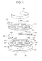
- FIG. 1 shows an exploded view of the light controlling apparatus
- Fig. 2 shows an assembly diagram of the light controlling apparatus.
- the light controlling apparatus includes a first substrate 101 in which a first aperture 102 is formed, a second substrate 201 in which a second aperture 202 which is larger than the first aperture 102, rotating shafts 203 and 204, and spacers 205, 206, and 207 are formed, a light controlling means (a light controlling mechanism) 301 in which a third aperture 302 which is smaller than the first aperture 102 and the second aperture 202, a drive shaft hole 304, and a rotating shaft hole 303 are formed, a transmission member 401 in which a rotating shaft hole 403 and a drive shafts 402 and 404 are formed, and an ion-conducting actuator 501 of which, one end is fixed to an electrode 502 which is fixed by adhering on the first substrate 101, and the other end is fixed by adhering to a coupling member 503.
- the rotating shaft 203 formed on the second substrate 201 is joined to the first substrate 101 via the rotating shaft hole 303 formed in the light controlling means 301.
- the rotating shaft 204 is joined to the first substrate 101 via the rotating shaft hole 403 formed in the transmission member 401.
- the drive shaft 402 formed in the transmission member 401 is inserted into the drive shaft hole 304 formed in the light controlling means 301, and the spacers 205 to 207 formed on the second substrate 201 are joined to the first substrate 101 directly.
- the drive shaft 404 formed on the transmission member 401 as shown in Fig. 2 is coupled with the ion-conducting actuator 501 by the coupling member 503. Furthermore, the first substrate 101 and the second substrate 201 which are coupled, the light controlling means 301, and the transmission member 401 are covered entirely by a frame member 601 having an aperture 602 which is larger than the first aperture 102.
- the circular arc shaped ion-conducting actuator 501 has a three-layered structure of an ion-containing polymer 511 which is a circular arc substrate, a first electrode 512 which is provided on a surface of a central side of the circular arc, and a second electrode 513 which is provided on a surface facing the surface of the central side of the circular arc.
- an electric potential difference is imparted between the first electrode 512 and the second electrode 513 by outputting a voltage from an external voltage source.
- Cations of the ion-containing polymer 511 move to a cathode side.
- the cathode side of the ion-conducting polymer 511 swells, and a curvature of the circular arc shape is changed as shown by dotted lines in Fig. 3 , which results in a change in a chord length.
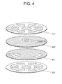
- a manufacturing process of a stacked structure excluding the ion-conducting actuator 501, the electrode 502, the coupling member 503, and the frame member 601 is shown in Fig. 4 , Fig. 5 , and Fig. 6 .
- diagrams in which the drive shafts 402 and 404, the rotating shafts 203 and 204, and the spacers 205, 206, and 207 are omitted are used.
- the stacked structure is manufactured by using a plating process and an etching process.
- each layer is made of a plating layer or plated layer which is a stacked structure, and a sacrificing layer which is removed by the etching after the stacking.
- each layer is shown to be disassembled such that each layer is clearly visible.
- various layers are stacked in order of a layer forming the second substrate 201, a sacrificing layer which is to be removed later, a layer of the transmission member 401, a sacrificing layer which is to be removed layer, a layer forming the light controlling means 301, a sacrificing layer which is to be removed later, and a layer forming the first substrate 101.
- Fig. 5 shows a diagram in which various layers are stacked.
- the stacked structure is formed as shown in Fig. 6 by removing the sacrificing layer formed in each layer, by the etching, after various layers are stacked.
- a space is to be formed in each layer.
- light is incident also from openings other than the first aperture 102 and the second aperture 202 formed in the first substrate 101 and the second substrate 201 respectively. Therefore, for using this stacked structure as the light controlling apparatus, by fitting the stacked structure in the frame member 601 shown in Fig. 1 , and shielding the apertures other than the first aperture 102 and the second aperture 202 formed in the first substrate 101 and the second substrate 201, it is possible to prevent the light from passing through the openings other than the first aperture 102 and the second aperture 202.
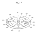
- Fig. 7 and Fig. 8 are diagrams in which, the first substrate 101, the ion-conducting actuator 501, the electrode 502, the coupling member 503, and the frame member 601 are omitted to make the diagrams easily understandable.
- the transmission member 401 is rotatable around the rotating shaft 204 as a center, which is formed in the second substrate 201.
- the light controlling means 301 is rotatable around the rotating shaft 203 as a center.
- the transmission member 401 and the light controlling means 301 are coupled by the drive shaft 402 formed on the transmission member 401.
- the transmission member 401 rotates, and with the rotation of the transmission member 401, the light controlling means 301 also rotates.
- the light controlling means 301 when the light controlling means 301 makes a contact with the spacer 205 upon coming to a first stationary position overlapping with the second aperture 202, the light controlling means 301 stops at that position. At this time, the third aperture 302 formed in the light controlling means 301 becomes an optical aperture of the light controlling apparatus. Moreover, as shown in Fig. 8 , when the light controlling means 301 rotates and comes to a second position which is a position retracted completely from the second aperture 202, the light controlling means 301 makes a contact with the spacer 206, and stops at that position.
- the first aperture 102 formed in the first substrate 101 becomes the optical aperture of the light controlling apparatus. In this manner, the optical aperture is switched by the rotation of the light controlling means 301.
- Fig. 9 and Fig. 10 are top views, and the first substrate 101 is omitted in Fig. 9 and Fig. 10 to make the operation of the mechanism easily understandable.
- Fig. 9 is a diagram showing a state in which, the light controlling means 301 makes a contact with the spacer 205, and is at the first stationary position overlapping with the second aperture 202.
- the third aperture 302 formed in the light controlling means 301 becomes the optical aperture of the light controlling apparatus in this state.
- the ion-conducting actuator 501 is fixed to the electrode 502, and is coupled with the drive shaft 404 formed on the transmission member 401, via the coupling member 503.
- the ion-conducting actuator 501 by supplying an electric power to the ion-conducting actuator 501 by the electrode 502, the curvature of the circular arc shape changes, and as a result, (the ion-conducting actuator 501) is displaced.
- the transmission member 401 coupled with the ion-conducting actuator 501 via the coupling member 503 rotates around the rotating shaft 204 formed on the second substrate 201, as a center
- the light controlling means 301 coupled with the drive shaft 402 formed on the transmission member 401 rotates around the rotating shaft 203 formed on the second substrate 201, as a center.
- the first aperture 102 formed in the first substrate 101 becomes the optical aperture of the light controlling apparatus.
- a front end of the coupling member 503 is formed to be ring-shaped, and is coupled with the drive shaft 404 formed on the transmission member 401.
- the shape of the front end of the coupling member 503 is a shape which can be hooked to the drive shaft 404, such as a shape in which a notch is formed in a rectangle, and not only the ring shape.
- the transmission member 401 which widens an amount of displacement of the ion-conducting actuator 501 is provided, and by coupling the transmission member 401 to the light controlling means 301, the displacement is transmitted upon increasing. Consequently, it is possible to reduce substantially the amount of displacement of the ion-conducting actuator 501 which is necessary for opening and closing the light controlling means 301. Therefore, it is possible to reduce substantially a voltage to be supplied to the ion-conducting actuator 501, and also to improve reliability of the ion-conducting actuator 501.
- the structure becomes large which is a problem.
- the stacked structure is manufactured by using the plating process and the etching process, such fine and complicated structure is possible. Furthermore, a self assembly in which an assembling process is not necessary is possible.
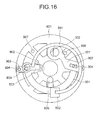
- Fig. 11 is a diagram showing an exploded view of a second embodiment of the light controlling apparatus according to the present invention.
- the second embodiment will be described below by using diagrams from Fig. 11 to Fig. 16 . Same reference numerals are assigned to components which are same as in the first embodiment, and the description of such components is omitted. A structure of the light controlling apparatus of the second embodiment will be described below.
- Fig. 11 is an exploded view of the light controlling apparatus.
- Fig. 12 is an assembly diagram in which the ion-conducting actuator 501, the coupling member 503, the electrode 502, and the frame member 601 are omitted.
- the light controlling apparatus includes a first substrate 701 in which a first aperture 702 is formed, a second substrate 801 in which a second aperture 802 which is larger than the first aperture 702, rotating shafts 803 and 804, and spacers 805, 806, and 807 are formed, a light controlling means 301 in which a third aperture 302 which is smaller than the first aperture 702 and the second aperture 802, a drive shaft hole 304, and a rotating shaft hole 303 are formed, a transmission member 901 in which a rotating shaft hole 903, a drive shaft 902, and a groove 904 are formed, and the ion-conducting actuator 501 of which, one end is fixed to the electrode 502 which is fixed by adhering on the substrate 701, and the other end is fixed by adhering to the coupling member 503.
- the rotating shaft 803 formed on the second substrate 801 is joined to the first substrate 701 via the rotating shaft hole 303 formed in the light controlling means 301.
- the rotating shaft 804 is joined to the first substrate 701 via the rotating shaft hole 903 formed in the transmission member 901.
- a drive shaft 809 connected to the drive bearing 808 is provided independently in a layer of the second substrate 801.
- the drive shaft 809 is protruded on the first substrate 701 via the groove 904 formed in the transmission member 901.
- the spacers 805, 806, and 807 formed on the second substrate 801 are joined directly to the first substrate 701. Moreover, it is not shown in the diagram but the drive shaft 809 protruded from the first substrate 701 is coupled with the ion-conducting actuator 501 by the coupling member 503. Furthermore, similarly as in the first embodiment, the first substrate 701, the second substrate 801, the light controlling means 301, and the transmission member 901 which are coupled are covered entirely by the frame member 601 having the aperture 602 lager than the first aperture 702.
- components other than the ion-conducting actuator 501, the electrode 502, the coupling member 503, and the frame member 601 form a stacked structure made of a plated layer, which is manufactured by using the plating process and the etching process, similarly as in the first embodiment.
- Fig. 13 and Fig. 14 are state diagrams in which the first substrate 701, the ion-conducting actuator 501, the electrode 502, the coupling member 503, and the frame member 601 are omitted for making the diagrams easily understandable.
- the transmission member 901 is rotatable around the rotating shaft 804 as a center, which is formed in the second substrate 801.
- the light controlling means 301 is rotatable around the rotating shaft 803 as a center.
- the transmission member 901 and the light controlling means 301 are coupled by the drive shaft 902 formed in the transmission member 901.
- the drive shaft 809 which is protruded from the groove 904 formed in the transmission member 901 is movable along the groove 94. In this manner, by operating the drive shaft 809, the transmission member 901 rotates, and with the rotation of the transmission member 901, the light controlling means 301 also rotates and switches the optical aperture.
- the light controlling means 301 when the light controlling means 301 makes a contact with the spacer 805 upon coming to a first stationary position overlapping with the second aperture 802, the light controlling means 301 stops at that position. At this time, the third aperture 302 formed in the light controlling means 301 becomes an optical aperture of the light controlling apparatus. Moreover, as shown in Fig. 14 , when the light controlling means 301 rotates and comes to a second position which is a position retracted completely from the second aperture 802, the light controlling means 301 makes a contact with the spacer 806, and stops at that position. It is not shown in the diagram, but at this time, the first aperture 702 formed in the first substrate 701 becomes the optical aperture of the light controlling apparatus. In this manner, the transmission member 901 rotates, and with the rotation of the transmission member 901, the light controlling means 301 also rotates, thereby switching the aperture.
- Fig. 15 and Fig. 16 are top views, and the first substrate 701 is omitted in Fig. 15 and Fig. 16 to make the operation of the mechanism easily understandable.
- Fig. 15 is a diagram when a voltage is applied.
- the light controlling means 301 makes a contact with the spacer 805, and is at the first stationary position overlapping with the second aperture 802 formed in the second substrate 801.
- the third aperture 302 formed in the light controlling mean 301 becomes the optical aperture of the light controlling apparatus in this state.
- the ion-conducting actuator 501 is fixed to the electrode 502, and is coupled with the drive shaft 809 protruded from the groove 904 which is formed in the transmission member 901 via the coupling member 503.
- the curvature of the circular arc shape of the ion-conducting actuator 501 changes due to a restoring force of the ion-conducting actuator 501, and as a result, the ion-conducting actuator 501 is displaced.
- the transmission member 901 coupled with the ion-conducting actuator 501 rotates around the rotating shaft 804 formed on the second substrate 801, as a center
- the light controlling means 301 coupled with the drive shaft 902 formed on the transmission member 901 rotates around the rotating shaft 803 formed on the second substrate 801, as a center.
- the front end of the coupling member 503 is formed to be ring-shaped, and is coupled with the drive shaft 809 protruded from the transmission member 901. It is possible to achieve a similar effect provided that the shape of the front end of the coupling member 503 is a shape which can be hooked to the drive shaft 809, such as a shape in which a notch is formed in a rectangle, and not only the ring shape.
- the transmission member 901 which transmits upon widening the amount of displacement to the light controlling means 301 since the transmission member 901 which transmits upon widening the amount of displacement to the light controlling means 301 is coupled, it is possible to reduce substantially the amount of displacement of the ion-conducting actuator 501 which is necessary for opening and closing the light controlling means 301.
- the drive shaft 809 which is coupled with the ion-conducting actuator 501 is movable not only in a direction (circumferential direction) in which the transmission member 901 is rotated, but also along the groove 904 in a radial direction formed in the transmission member 901.
- the displacement of the ion-conducting actuator 501 having the circular arc shape includes not only a displacement in the circumferential direction but also a displacement in a radial direction.
- the movement in the radial direction of the ion-conducting actuator 501 is not regulated. Furthermore, it is possible to impart a degree of freedom to the disposing the arrangement of the ion-conducting actuator 501.
- the stacked structure is manufactured by the plating process and the etching process.
- the transmission member which transmits upon widening the displacement of the ion-conducting actuator is provided, and this transmission member is coupled with the light controlling means.
- this transmission member is coupled with the light controlling means.
- the light controlling apparatus according to the present invention is useful in an endoscope in which a solid image pickup element is used, and particularly is suitable for a small-size light controlling apparatus to be used in an endoscope of a thin diameter.
- an ultra-small light controlling apparatus in which an opening and closing operation of a diaphragm blade is possible by a small displacement of an actuator.
Landscapes
- Health & Medical Sciences (AREA)
- Life Sciences & Earth Sciences (AREA)
- Surgery (AREA)
- Physics & Mathematics (AREA)
- Engineering & Computer Science (AREA)
- Medical Informatics (AREA)
- Optics & Photonics (AREA)
- Pathology (AREA)
- Radiology & Medical Imaging (AREA)
- Biophysics (AREA)
- General Physics & Mathematics (AREA)
- Biomedical Technology (AREA)
- Heart & Thoracic Surgery (AREA)
- Nuclear Medicine, Radiotherapy & Molecular Imaging (AREA)
- Molecular Biology (AREA)
- Animal Behavior & Ethology (AREA)
- General Health & Medical Sciences (AREA)
- Public Health (AREA)
- Veterinary Medicine (AREA)
- Diaphragms For Cameras (AREA)
- Mechanical Light Control Or Optical Switches (AREA)
Applications Claiming Priority (1)
| Application Number | Priority Date | Filing Date | Title |
|---|---|---|---|
| JP2008146599A JP2009294342A (ja) | 2008-06-04 | 2008-06-04 | 光調節装置 |
Publications (1)
| Publication Number | Publication Date |
|---|---|
| EP2131237A1 true EP2131237A1 (de) | 2009-12-09 |
Family
ID=40908571
Family Applications (1)
| Application Number | Title | Priority Date | Filing Date |
|---|---|---|---|
| EP09161488A Withdrawn EP2131237A1 (de) | 2008-06-04 | 2009-05-29 | Lichtsteuerungsvorrichtung |
Country Status (3)
| Country | Link |
|---|---|
| US (1) | US20090304378A1 (de) |
| EP (1) | EP2131237A1 (de) |
| JP (1) | JP2009294342A (de) |
Families Citing this family (2)
| Publication number | Priority date | Publication date | Assignee | Title |
|---|---|---|---|---|
| JP5576729B2 (ja) * | 2010-07-05 | 2014-08-20 | オリンパス株式会社 | 光調節装置 |
| US11422432B2 (en) * | 2020-06-18 | 2022-08-23 | Tdk Taiwan Corp. | Lens assembly for a mobile device having an adjustable diaphragm device |
Citations (5)
| Publication number | Priority date | Publication date | Assignee | Title |
|---|---|---|---|---|
| US6449436B1 (en) * | 2001-04-04 | 2002-09-10 | Eastman Kodak Company | Aperture adjustment using shaped memory alloy |
| US20070098399A1 (en) * | 2005-11-01 | 2007-05-03 | Olympus Corporation | Optical diaphragm apparatus |
| US20070098398A1 (en) * | 2005-11-01 | 2007-05-03 | Fujifilm Corporation | Image taking apparatus |
| US20070219459A1 (en) * | 2005-10-14 | 2007-09-20 | Microfabrica Inc. | Biopsy Devices, Methods for Using, and Methods for Making |
| US20080050112A1 (en) * | 2006-08-22 | 2008-02-28 | Sony Ericsson Mobile Communications Ab | Camera shutter |
Family Cites Families (10)
| Publication number | Priority date | Publication date | Assignee | Title |
|---|---|---|---|---|
| FR2440013A1 (fr) * | 1978-10-23 | 1980-05-23 | Canon Kk | Obturateur a diaphragme actionne electromagnetiquement |
| JPS61144631A (ja) * | 1984-12-18 | 1986-07-02 | Matsushita Electric Ind Co Ltd | 絞り装置 |
| JPS63287931A (ja) * | 1987-05-21 | 1988-11-25 | Olympus Optical Co Ltd | カメラの絞り装置 |
| JP3723645B2 (ja) * | 1996-09-20 | 2005-12-07 | ペンタックス株式会社 | 絞り機構の絞り原点調整方法および装置 |
| JP2003009555A (ja) * | 2001-06-25 | 2003-01-10 | Canon Inc | 積層電気−機械エネルギー変換素子および振動波駆動装置 |
| US7570882B2 (en) * | 2005-02-28 | 2009-08-04 | Samsung Electronics Co., Ltd. | Shutter for miniature camera |
| JP4849516B2 (ja) * | 2005-10-21 | 2012-01-11 | キヤノン株式会社 | 駆動装置及び光量調節装置 |
| US7708478B2 (en) * | 2006-04-13 | 2010-05-04 | Nokia Corporation | Actuator mechanism and a shutter mechanism |
| JP2008086063A (ja) * | 2006-09-26 | 2008-04-10 | Olympus Corp | 高分子アクチュエータ装置及び光学絞り装置 |
| JP2009008719A (ja) * | 2007-06-26 | 2009-01-15 | Olympus Corp | 光調節装置及び光学装置 |
-
2008
- 2008-06-04 JP JP2008146599A patent/JP2009294342A/ja active Pending
-
2009
- 2009-05-29 EP EP09161488A patent/EP2131237A1/de not_active Withdrawn
- 2009-06-04 US US12/478,191 patent/US20090304378A1/en not_active Abandoned
Patent Citations (6)
| Publication number | Priority date | Publication date | Assignee | Title |
|---|---|---|---|---|
| US6449436B1 (en) * | 2001-04-04 | 2002-09-10 | Eastman Kodak Company | Aperture adjustment using shaped memory alloy |
| US20070219459A1 (en) * | 2005-10-14 | 2007-09-20 | Microfabrica Inc. | Biopsy Devices, Methods for Using, and Methods for Making |
| US20070098399A1 (en) * | 2005-11-01 | 2007-05-03 | Olympus Corporation | Optical diaphragm apparatus |
| US20070098398A1 (en) * | 2005-11-01 | 2007-05-03 | Fujifilm Corporation | Image taking apparatus |
| JP2007127699A (ja) | 2005-11-01 | 2007-05-24 | Olympus Corp | 光学絞り装置 |
| US20080050112A1 (en) * | 2006-08-22 | 2008-02-28 | Sony Ericsson Mobile Communications Ab | Camera shutter |
Also Published As
| Publication number | Publication date |
|---|---|
| US20090304378A1 (en) | 2009-12-10 |
| JP2009294342A (ja) | 2009-12-17 |
Similar Documents
| Publication | Publication Date | Title |
|---|---|---|
| JP5414417B2 (ja) | ズームレンズ鏡筒 | |
| US8422154B2 (en) | Light adjusting apparatus | |
| US8077403B2 (en) | Lens barrel | |
| KR20090038454A (ko) | 촬상 장치 | |
| JP4674787B2 (ja) | レンズ鏡筒およびカメラ | |
| US6965486B2 (en) | Zoom camera having lens barrel assembly adjustable focus and resolution power of lens | |
| EP2131237A1 (de) | Lichtsteuerungsvorrichtung | |
| JP2008257028A (ja) | 入射光調節装置 | |
| US20070098399A1 (en) | Optical diaphragm apparatus | |
| JP6399770B2 (ja) | 光量調整装置、レンズ鏡筒、光学機器および撮像装置 | |
| JP2011033910A (ja) | 光調節装置 | |
| CN102681291A (zh) | 光圈装置、摄像机以及电子设备 | |
| KR20080068532A (ko) | 광량 조정 장치 및 촬상 장치 | |
| US6879445B2 (en) | Power/manual lens barrel having a manual operating ring | |
| JP2006047673A (ja) | レンズユニットおよび撮像装置 | |
| JP3328036B2 (ja) | 鏡枠移動機構 | |
| US8602664B2 (en) | Lens barrel and image pickup apparatus | |
| JP3429644B2 (ja) | レンズ鏡筒 | |
| JP2007079390A (ja) | レンズ駆動装置 | |
| JP3387626B2 (ja) | レンズ鏡筒 | |
| JPH1172684A (ja) | レンズ鏡筒 | |
| JP5460171B2 (ja) | 光学装置 | |
| JP2001208949A (ja) | 付勢部材、環状部材及びレンズ鏡筒 | |
| EP4137886A1 (de) | Blendenvorrichtung, kameramodul mit blendenvorrichtung und elektronische vorrichtung | |
| JP4623364B2 (ja) | 撮像装置及び駆動モーター |
Legal Events
| Date | Code | Title | Description |
|---|---|---|---|
| PUAI | Public reference made under article 153(3) epc to a published international application that has entered the european phase |
Free format text: ORIGINAL CODE: 0009012 |
|
| AK | Designated contracting states |
Kind code of ref document: A1 Designated state(s): AT BE BG CH CY CZ DE DK EE ES FI FR GB GR HR HU IE IS IT LI LT LU LV MC MK MT NL NO PL PT RO SE SI SK TR |
|
| STAA | Information on the status of an ep patent application or granted ep patent |
Free format text: STATUS: THE APPLICATION IS DEEMED TO BE WITHDRAWN |
|
| 18D | Application deemed to be withdrawn |
Effective date: 20100610 |