EP2129641B1 - Verfahren zur herstellung monolithischer gaserzeugender körner - Google Patents
Verfahren zur herstellung monolithischer gaserzeugender körner Download PDFInfo
- Publication number
- EP2129641B1 EP2129641B1 EP08742004.8A EP08742004A EP2129641B1 EP 2129641 B1 EP2129641 B1 EP 2129641B1 EP 08742004 A EP08742004 A EP 08742004A EP 2129641 B1 EP2129641 B1 EP 2129641B1
- Authority
- EP
- European Patent Office
- Prior art keywords
- gas generant
- grain
- gas
- monolithic
- pressure
- Prior art date
- Legal status (The legal status is an assumption and is not a legal conclusion. Google has not performed a legal analysis and makes no representation as to the accuracy of the status listed.)
- Active
Links
Images




Classifications
-
- C—CHEMISTRY; METALLURGY
- C06—EXPLOSIVES; MATCHES
- C06B—EXPLOSIVES OR THERMIC COMPOSITIONS; MANUFACTURE THEREOF; USE OF SINGLE SUBSTANCES AS EXPLOSIVES
- C06B45/00—Compositions or products which are defined by structure or arrangement of component of product
-
- B—PERFORMING OPERATIONS; TRANSPORTING
- B01—PHYSICAL OR CHEMICAL PROCESSES OR APPARATUS IN GENERAL
- B01J—CHEMICAL OR PHYSICAL PROCESSES, e.g. CATALYSIS OR COLLOID CHEMISTRY; THEIR RELEVANT APPARATUS
- B01J2/00—Processes or devices for granulating materials, e.g. fertilisers in general; Rendering particulate materials free flowing in general, e.g. making them hydrophobic
- B01J2/22—Processes or devices for granulating materials, e.g. fertilisers in general; Rendering particulate materials free flowing in general, e.g. making them hydrophobic by pressing in moulds or between rollers
-
- C—CHEMISTRY; METALLURGY
- C06—EXPLOSIVES; MATCHES
- C06B—EXPLOSIVES OR THERMIC COMPOSITIONS; MANUFACTURE THEREOF; USE OF SINGLE SUBSTANCES AS EXPLOSIVES
- C06B21/00—Apparatus or methods for working-up explosives, e.g. forming, cutting, drying
- C06B21/0033—Shaping the mixture
- C06B21/0041—Shaping the mixture by compression
-
- C—CHEMISTRY; METALLURGY
- C06—EXPLOSIVES; MATCHES
- C06D—MEANS FOR GENERATING SMOKE OR MIST; GAS-ATTACK COMPOSITIONS; GENERATION OF GAS FOR BLASTING OR PROPULSION (CHEMICAL PART)
- C06D5/00—Generation of pressure gas, e.g. for blasting cartridges, starting cartridges, rockets
- C06D5/06—Generation of pressure gas, e.g. for blasting cartridges, starting cartridges, rockets by reaction of two or more solids
Definitions
- the present disclosure relates to inflatable restraint systems and more particularly to methods of manufacturing pyrotechnic gas generant materials for use in such systems.
- Passive inflatable restraint systems are often used in a variety of applications, such as in motor vehicles.
- an inflatable restraint system deploys an airbag cushion to prevent contact between the occupant and the vehicle, thus minimizing occupant injuries.
- Such devices usually employ an inflator that can include a pyrotechnic gas generant. The gas generants burn very rapidly to generate heated gas that inflates an airbag, thereby restraining the occupant relative to the vehicle.
- Vehicle occupants may not be in a predetermined position to receive the complete benefits of airbag deployment. If the rate of pressure increase in the airbag is too rapid and the amount of pressure generated by the gas generant is excessive, then an out-of-position occupant may not receive the desired benefits of the airbag. There is an ever growing demand to improve airbag performance and safety, as well as a need to reduce manufacturing and production costs. Accordingly, there is a need for increasing the functionality of the propellant or gas generant used in airbag inflators, while reducing the cost of the gas generant and entire airbag inflator system.
- gas generant performance remains desirable. Tailoring the performance of the gas generant in an inflatable device system, such as an airbag, can require a complex design of not only the gas generant, but also hardware systems that control gas flow. It is preferred that gas generants for inflators of inflatable restraint devices rapidly generate gases during combustion at desired pressure levels and rates to achieve superior performance and to improve out-of-position performance. Likewise, gas generant materials are preferably safe for handling, have high gas yields and acceptable flame temperatures, with burning rates appropriate to the generant web thickness. Gas generants that fulfill these requirements and further minimize the production of byproduct compounds in effluent gases released through the airbag are highly desirable.
- WO 2006/134311 discloses a process of dry mixing, compacting, granulation and compacting of gas generating compositions. It is considered to be well-suited for compositions comprising guanidine nitrate. Ballistic performance modifiers are not mentioned.
- Other prior art is described in the following documents : US 6143102 , US 2004/173922 , US 4000231 , US 5879421 , WO 89/10257 , GB 2219242 , US 5202067 , US 2002/039603 , US 6039820 , US 2003/089883 , US 6958101 and WO 2004/024653 .
- the disclosure provides a method for forming a monolithic gas generant comprising introducing a gas generant material into a die cavity.
- the die cavity has a first side and a second side opposite to the first side.
- Pressure is applied to the gas generant material along both the first and the second sides to form a pressed monolithic grain that has an actual density of greater than or equal to about 95% of the maximum theoretical mass density of the gas generant material.
- the pressed monolithic grain is ejected from the die by applying a greater pressure on the first side to force the grain from the die, while maintaining applied pressure on the second side during at least a portion of the ejecting, where the applied pressure is greater than or equal to about 3,000 psig (pounds per square inch gauge) (about 21 MPa).
- the present disclosure provides a method for forming a monolithic gas generant.
- the gas generant material is admixed with a ballistic performance modifier to form a mixture.
- the mixture is compacted with an applied pressure of at least about 40,000 psi (276 MPa) on generant.
- the mixture is granulated.
- a pressed monolithic gas generant grain is formed by applying pressure of greater than about 70,000 psi (about 480 MPa) to the granulated mixture, where the pressed monolithic gas generant grain has an initial surface area of less than about 13,000 mm 2 , wherein a product of a mass density and a gas yield of the gas generant is greater than or equal to about 5.0 moles/100 cm 3 .
- the gas generant grain is substantially free of polymeric binder and has an actual density of at least about 95% of the maximum theoretical density of the gas generant.
- Inflatable restraint devices preferably generate gas in situ from a reaction of a pyrotechnic gas generant contained therein.
- gas generants are formed that have desirable compositions and shapes that result in superior performance characteristics in an inflatable restraint device.
- the disclosure provides methods of making monolithic gas generant grains that have a high burn rate (i.e ., rate of combustion reaction), a high gas yield (moles/mass of generant), a high achieved mass density, a high theoretical density, and a high loading density.
- the monolithic gas generants are substantially free of polymeric binder and have a high density. Such monolithic gas generant grains are formed in unique shapes that optimize the ballistic burning profiles of the materials contained therein.
- inflatable restraint devices have applicability for various types of airbag module assemblies for automotive vehicles, such as driver side, passenger side, side impact, curtain and carpet airbag assemblies, for example, as well as with other types of vehicles including, for example, boats, airplanes, and trains.
- pyrotechnic gas generants can also be used in other applications where rapid generation of gas is required, such as seat belt restraints, for example.
- FIG. 1 shows an exemplary driver-side front airbag inflatable restraint device 10.
- driver side, inflatable restraint devices typically comprise an airbag cushion 12 that is stored within a steering column 14 of a vehicle 16.
- a gas generant contained in an inflator (not shown) in the steering column 14 creates rapidly expanding gas 18 that inflates the airbag 12.
- the airbag 12 deploys within milliseconds of detection of deceleration of the vehicle 16 and creates a barrier between a vehicle occupant 20 and the vehicle components 22, thus minimizing injuries.
- Inflatable restraint devices typically involve a series of reactions, which facilitate production of inflation gas to deploy the airbag. Upon actuation of the entire airbag assembly system, the airbag cushion should begin to inflate within the course of a few milliseconds.
- FIG. 2 shows a simplified exemplary airbag module 30 comprising a passenger compartment inflator assembly 32 and a covered compartment 34 to store an airbag 36.
- a squib or initiator 40 which is electrically ignited when rapid deceleration and/or collision is sensed.
- the discharge from the squib 40 usually ignites an igniter material 42 that burns rapidly and exothermically, in turn, igniting a gas generant material 50.
- the gas generant material 50 burns to produce the majority of gas products that are directed to the airbag 36 to provide inflation.
- a gas generant 50 is a solid grain that comprises a pyrotechnic material.
- the pyrotechnic material consists of a fuel, an oxidizer, and other minor ingredients that when ignited combust rapidly to form gaseous reaction products (for example, CO 2 , H 2 O, and N 2 ).
- Gas generants are also known in the art as propellants.
- a gas generant material comprises one or more compounds (e.g ., raw materials) that are combined into a unitary structure that when ignited undergo rapid combustion reaction(s) forming heat and gaseous products, i.e., the gas generant 50 burns to create heated inflation gas for an inflatable restraint device.
- a gas generant 50 is a solid grain that comprises a pyrotechnic material. It is desirable to formulate the gas generant composition such that the solid combustion products form a unitary, easily filterable mass, sometimes referred to as a clinker, during combustion. The clinker often serves to sequester various particulates. However, a filter 52 is often additionally provided between the gas generant 50 and airbag 36 to remove particulates entrained in the gas and to reduce gas temperature of the gases prior to entering the airbag 36. The quality and toxicity of the components of the gas produced by the gas generant 50, also referred to as effluent, are important because occupants of the vehicle may be potentially exposed to these compounds. Therefore, it is desirable to minimize the concentration of potentially harmful compounds in the effluent.
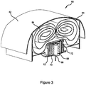
- Figure 3 shows a simplified exemplary driver side airbag module 60 with a covered compartment 62 to store an airbag 64.
- a squib 66 is centrally disposed within an igniter material 68 that burns rapidly and exothermically, in turn, igniting a gas generant material 70.
- Filters 72 are provided to reduce particulate in effluent gases entering the airbag 64 as it inflates.
- gas generant compositions are used in vehicular occupant inflatable restraint systems.
- gas generant material selection involves various factors, including meeting current industry performance specifications, guidelines and standards, generating safe gases or effluents, handling safety of the gas generant materials, durational stability of the materials, and cost-effectiveness in manufacture, among other considerations. It is preferred that the gas generant compositions are safe during handling, storage, and disposal, and preferably are azide-free.
- the present disclosure provides methods of making pressed monolithic gas generant grains that have a high density, strength to withstand environmental conditions and ignition, a consistency of shape from grain to grain, and further lack flaws in the grain such as cracks, chips, voids, and the like.
- gas generant material composition such as 50 or 70 shown in Figures 2 and 3
- gas generant material composition typically controlled by the gas generant material composition, shape and surface area, as well as the burn rate of the material.
- Conventional gas generant materials comprise at least one fuel, an oxidizer, and at least one binder, such as a polymeric binder. Binders are typically mixed with the various constituents of the gas generant. Binders often serve to retain the shape of and to prevent the fracture of the gas generant solids during storage and use, particularly when they are formed via extrusion and/or molding. For example, a dry blended mixture of various gas generant raw material components can be mixed with a liquid binder resin, extruded, and then cured.
- solid polymeric binder particles can be dissolved in a solvent or heated to the melting point, then mixed with other gas generant components and extruded or molded.
- gas generant solids formed by such methods are only subjected to relatively low to moderate compressive forces due to the nature of the manufacturing methods and relative compressive force applied.
- binder such as polymeric binders, including organic film formers, inorganic polymers, thermoplastic and/or thermoset polymers.
- polymeric binders include, but are not limited to: natural gums, cellulosic esters, polyacrylates, polystyrenes, silicones, polyesters, polyethers, polybutadiene, and the like.
- binder resin is a diluent and slows otherwise rapid reaction of the chemical materials in the gas generant.
- the burning rate of gas generants having certain binders is so severely compromised that monolithic shapes have previously not been industrial practicable. Since the presence of the binder slows the rate of reaction of the gas generant, other compounds are often added to compensate for the binder (thereby boosting the reaction rate).
- additives include co-oxidants, such as perchlorate-containing oxidants, which create unfilterable particulates in the effluent.
- the gas generant materials are substantially free of polymeric binder.
- a gas generant that is "substantially free" of polymeric binder comprises less than about 5% by weight polymeric binder, more preferably less than about 4% by weight, optionally less than about 3% by weight, optionally less than about 2% by weight, optionally less than about 1% by weight polymeric binder, and in certain embodiments comprises 0% by weight of the polymeric binder.
- gas generant compositions formed in accordance with the principles of the present disclosure thus avoid production of undesirable byproduct species potentially generated in effluent by the burning of the polymeric binder resins as the gas generant burns. Further, gas generants that are substantially free of polymeric binders have significantly improved burn characteristics ( i.e., higher burning rate).
- the methods of the present disclosure provide gas generant materials that are monolithic pressed grain shapes having a high density.
- gas generant grains raw materials are mixed and then processed.
- the variability in raw material properties of the various components of the gas generant can potentially result in variability in the gas generant grain, which in turn can potentially cause inconsistent ballistic performance.
- this inherent lot to lot variation in performance can be adjusted by simply adjusting gas generant load or thickness.
- monolithic pressed grains there are potential concerns that monolithic pressed grains lack "tunability" or an inability to compensate for inherent lot to lot variation in performance.
- the present disclosure provides methods of forming monolithic gas generant grains by flexible manufacturing processes that account for such potential variations from manufacturing.
- the methods of the present disclosure provide gas generant materials that are monolithic pressed grain shapes that have a high density, for example, and have an actual density that is greater than or equal to about 90% of the maximum theoretical density of the gas generant.
- the actual density is greater than or equal to about 93%, more preferably greater than about 95% of the maximum theoretical density, and even more preferably greater than about 97% of the maximum theoretical density. In some embodiments, the actual density exceeds about 98% of the maximum theoretical density of the gas generant material.
- Such high actual mass densities in gas generant materials are obtained in certain methods of forming gas generant grains in accordance with various aspects of the present disclosure, where high compressive force is applied to gas generant raw materials that are substantially free of binder.
- the pressed monolithic grains formed by the methods of the present disclosure have a loading density of the gas generant that is relatively high; otherwise a low performance for a given envelope may result.
- a loading density is an actual volume of generant material divided by the total volume available for the shape.
- the gas generant grains have a loading density for the gas generant that is greater than or equal to about 60%, optionally greater than or equal to about 62%. In certain aspects, a gas generant has a loading density of about 62 to about 63%.
- a method for forming a pressed monolithic gas generant grain includes admixing a gas generant material with a ballistic performance modifier to form a mixture. The mixture is then granulated. A pressed monolithic gas generant grain is formed by applying pressure to the granulated mixture. The resulting pressed monolithic gas generant grain has an actual density of at least about 95% of the maximum theoretical density of the gas generant. In some aspects, the mixture is compacted by applying pressure of at least about 40,000 PSI (about 275 MPa) to the gas generant by the use of powder densification equipment (other presses or Roll compaction) prior to granulating the mixture. The methods herein described permit "tuning out" of the lot to lot performance variation. Such a manufacturing process further creates a desirable monolithic grain that meets all of the performance and effluent requirements.
- Gas generant raw materials are used to prepare gas generant material at 300.
- the various gas generant raw materials will be discussed in more detail below; however, such components typically include at least one fuel and at least one oxidizer.
- the gas generant powder is prepared at 300 via one or more of the following processes: spray drying, dry blending, and wet granulation.
- the powder preparation and processing is conducted by creating a slurry by distributing and thoroughly mixing the several raw material components in water and/or a hydrophilic solvent, followed by drying (e.g., spray drying).
- drying e.g., spray drying
- preparation of the gas generant powder is unnecessary as the gas generants are commercially available and/or otherwise prepared in advance. Where the gas generant powder preparation is conducted, quality control and the formation of an intimate mixture of the several gas generant ingredients (raw materials) can be ensured, thereby increasing the burning rate of the gas generant formulation. Further, preparation of the gas generant powder 300 enables safe handling of sensitive ingredients by dilution with other gas generant materials.
- Figure 4 shows that after preparing the gas generant powder, one or more ballistic properties of the gas generant material can be determined by measuring and/or testing the gas generant at 310.
- One or more of such measurements of the gas generant materials can be obtained, i.e., step 310 can be repeated.
- Ballistic properties that can be tested include burn rate, linear burn rate, and/or gas yield.
- one or more of such measurements are selected from the group consisting of: heat of explosion (HEX) and material density (mass/volume).
- HEX heat of explosion
- mass/volume mass/volume
- the heat of explosion is usually defined as the energy released by burning a material in an inert atmosphere (e.g ., 20 atm N 2 ),which is then cooled to ambient temperature in a fixed volume, as is well known to those of skill in the art.
- an inert atmosphere e.g . 20 atm N 2
- the measurement of one or more ballistic properties informs a determination of the amount of gas generant to be added to a predetermined volume of monolithic gas generant.
- these measurements permit comparison to desired baseline target values for each parameter for an exemplary desired monolithic gas generant grain, thus enabling tuning of the performance characteristics of the gas generant grain by varying a concentration of the gas generant and one or more ballistic performance modifying agents.
- a ballistic performance modifier is an agent that modifies one or more ballistic properties of the gas generant grain, for example, cooling the flame temperature, increasing the burn rate, and the like.
- the amount of performance modifier is adjusted to achieve uniform ballistic performance from batch to batch.
- determining one or more ballistic properties of a performance modifier is also useful for predicting ballistic performance of the mixture of gas generant and ballistic performance modifier.
- performance modifying agents will be described in more detail below.
- the gas generant powder is admixed with a ballistic performance modifier at 320.
- the admixing at 320 optionally includes introducing a first amount of gas generant and a second amount of ballistic performance modifier.
- the first amount of gas generant and the second amount of ballistic performance modifier relates to the ballistic properties of the gas generant material that are determined in step 310, and optionally based on a determination of one or more ballistic properties of the performance modifier (which may be obtained from a manufacturer or by testing).
- the mixing is conducted so that the gas generant and the performance modifier are well mixed, preferably homogeneously mixed, to form a mixture, preferably a homogeneous mixture.
- the gas generant grain can optionally be added and admixed with the gas generant powder at 320.
- the mixture comprises a press release aid agent, which is introduced to the gas generant and performance modifier prior to or during the admixing process.
- the mixture of gas generant and performance modifier is compacted followed by granulation of the compacted mixture 350.
- the mixture is compacted by granulation by the use of powder densification equipment, such as presses or roll compaction equipment well known to those of skill in the art.
- a minimum pressure for densification applied to the mixture is about 40,000 psi (275 MPa).
- the compaction prior to granulation is optional.
- the compaction 340 and/or granulation 350 steps serve to densify the mixture so that it can be charged into the die prior to pressing and moreover, the compaction/granulation processes can cause certain gas generant raw materials to flow under pressure.
- this flow of raw material is desirable because it incorporates the dry blended performance modifier into a matrix of the gas generant, thus preventing segregation of components later in the process.
- certain water-soluble co-fuels such as guanidine nitrate or dicyandiamide act as a non-polymeric binder in the gas generant grain.
- the granulated mixture is introduced or charged into a die cavity (a die or a mold), where an applied force or pressure compresses the granulated materials to form a desired monolithic grain shape.
- the granules are pressed into a monolithic grain by application of pressure at step 360.
- the pressing forms the mixture into a desired shape that permits the inflator to perform in the prescribed manner.
- a pressed monolithic gas generant grain is formed which has a high density, a high strength to withstand environmental conditions and ignition, consistency of shape from grain to grain, and the absence of flaws in the grain such as cracks, chips, voids, and the like.
- the forming of the pressed gas generant grain is conducted in a hydraulic press where a granulated mixture is introduced into a die cavity.
- the application of pressure can be achieved by any pressing operation that provides the necessary applied compression force, as known to those of skill in the art, and is not limited to hydraulic pressing.
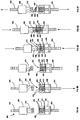
- Figures 5A-5F depict stages of an exemplary pressing process using a simplified depiction of a hydraulic press 400 for forming a gas generant grain.
- the hydraulic press 400 comprises an upper hydraulic cylinder 402 and a lower hydraulic cylinder 404.
- An upper platen 406 is attached to the upper hydraulic cylinder 402.
- the lower hydraulic cylinder 404 is attached to a lower platen 408.
- An upper punch 410 is attached to the upper platen 406.
- a lower punch 412 is attached to the lower platen 408.
- a stationary die 414 is mounted to a bottom portion (not shown) of the hydraulic press 400.
- a plurality of core pins 416 is also mounted to the bottom portion of the press 400. The pins 416 create void space or apertures within a gas generant material (420 of Figure 5C ) as pressure is applied; resulting in the formation of one or more apertures (422 of Figure 5F ) in a gas generant grain (424 of Figure 5F ).
- the lower punch 412 moves in a vertical direction around the plurality of core pins 416.
- the core pins 416 are flush with an upper surface 430 of the die 414.
- the lower punch 412 is also flush with the upper surface 430 of the die 414.
- lower cylinder 404 moves the lower punch 412 to a pre-determined lower position, thereby creating a void region 432 that has a suitable predetermined volume, to which a gas generant material (420 of Figure 5C ) can be added.
- a feed shoe (not shown) containing granulated gas generant material moves over a central region 434 of the die 414 to fill the void region(s) 432 with a gas generant material 420, as shown in Figure 5C . Any excess gas generant material 420 outside the central region 434 of the die 414 is removed.
- Figure 5C shows gas generant material 420 occupying the void regions 432 in the central region 434 of the die 414.
- a first side 436 of the gas generant material 420 contacts the lower punch 412.
- the upper cylinder 402 moves the upper punch 410 into contact with the gas generant material 420 within the die 414.
- the upper punch 410 contacts a second surface 438 of the gas generant material 420.
- the upper punch 410 has a plurality of apertures 440 ( Figure 5C ) that are adapted to receive the plurality of core pins 416.
- the upper punch 410 and the lower punch 412 are forced towards one another to apply force to the gas generant material 420.
- the methods of the disclosure optionally include a pre-compression cycle, where an applied force is exerted by the upper and/or lower punches 410,412 onto the gas generant material 420 at a lower pressure than a peak consolidation pressure.
- a pre-compression cycle allows for deaeration of the gas generant material 420 in controlled manner, thus improving the physical properties of the pressed monolithic gas generant grain 424, such as density and strength.
- the pre-press dwell pressure applied by the upper and lower punches 410, 412 via the upper and lower cylinders 402, 404 is optionally greater than about 5,000 psig (about 35 MPa), in some aspects, greater than about 10,000 psig, (about 70 MPa), and optionally about 14,000 psig (about 96 MPa). In some aspects, the pre-press dwell pressure is less than about 20,000 psig (about 138 MPa). In certain aspects, the pre-press dwell time is greater than about 0.1 seconds and less than about 3 seconds.
- the upper punch 410 protrudes into the central region 434 of the die 414 and contacts the gas generant material 420 at the second surface 438.
- a maximum pressure applied to the gas generant material 420 during grain formation is referred to as consolidation pressure.
- a consolidation pressure dwell time is the period during which the peak consolidation pressure is applied.
- the disclosure provides a method of forming a monolithic grain 424 comprising applying pressure to a granulated gas generant material mixture 420 charged into a die cavity 414, where the pressure is applied along a first side 436 of the gas generant material mixture 420 at a first contact surface 442 of the lower punch 412 and also along a second side 438 at a second contact surface 444 of the upper punch 410 to form the pressed monolithic grain 424.
- the consolidation pressure is the maximum pressure which is applied to form the grain 424.
- the consolidation pressure is greater than about 50,000 psig (about 345 MPa), optionally greater than about 90,000 psig (about 620 MPa), although optionally can be greater than 90,000 psig (about 620 MPa).
- the consolidation pressure ranges from about 50,000 psi (about 345 MPa) to about 70,000 psi (about 480 MPa), and optionally greater than about 90,000 psi (about 620 MPa).
- a dwell-time of the upper and lower punches 410, 412 at the consolidation pressure is preferably greater than about 0.1 seconds. In certain aspects, the dwell time at peak consolidation pressure is less than about 5 seconds.
- the lower punch 412 is raised such that the first contact surface 436 is flush with and/or raised above the upper surface 430 of the die 414.
- the upper punch 410 is likewise raised above the upper surface 430.
- little or negligible pressure is applied by the upper punch 410 to the grain 424 as the grain 424 is ejected, as the lower punch 412 typically raises and expels the grain 424 from the die 414 while the upper punch 410 is quickly raised out of contact with the grain 424 to provide clearance for grain 424 to be removed.
- the pressed monolithic grain 424 is released or ejected from the die 414 by moving the upper and lower punches 410, 412 in the same direction (e.g., up and out of the central region of the die above the upper die surface 430), while still applying pressure to both the upper and lower punches 410, 412.
- the upper punch 410 moves at a slightly faster speed than the lower punch 412, while both punches 410, 412 travel in the same (upward) direction, while still maintaining axial pressure on the grain 424 as it is removed from the die 414 and the core pins 416.
- a greater pressure is applied along the first side 436 (via the first contact surface 442 of the lower punch 412) to raise the grain 424 above an upper surface 430 of the die 414 and to remove the grain 424 from the die 414.
- the pressure can be maintained on the grain 424 along the second side 438 (via the second contact surface 444 with the upper punch 410), while pressure is concurrently being applied along the first side 436.
- the applied pressure is maintained on the first and second sides 436, 438 of the grain 424 during at least a portion of the time that the grain 424 is being ejected from the die 414.
- pressure is maintained on the first side and second sides 436, 438 of the grain 424 while the pins 416 are removed from the grain 424.
- the pressure during a portion of release or ejection on the second side 438 is greater than or equal to about 3,000 psig (21 MPa).
- the ejection pressure at the upper contact surface 444 optionally ranges from greater than about 3,200 psig (22 MPa) psig-to about 6,700 psig (46 MPa).
- the pins 416 are attached to a third cylinder (not shown), which is moved independently of the first and second cylinders 402, 404.
- the pins 416 or core rods "float.”
- the pins 416 or core rods move up with the grain 424 and lower punch 412.
- the pins 416 are lowered by the third cylinder and thus removed from the grain 424.
- Figure 5F shows a sectional view of the pressed monolithic gas generant grain 424 having apertures 422 as it is removed from the press. The steps in Figures 5B-5F are then repeated to form additional pressed monolithic gas generant grains.
- a press release aid agent is added to the gas generant material mixture (as described above during granulation and/or admixing) or alternately, directly onto the tooling surfaces, such as the inner surface of the die cavity, punches, and/or pin surfaces, to facilitate removal of the grain after consolidation, thereby reducing release forces on the grain.
- suitable press release aid agents include graphite, magnesium stearate, calcium stearate, and mixtures thereof, as are well known to those of skill in the art.
- the concentration of press release aid agent is generally related to the equivalent release force from the die. For example, graphite can be added at concentrations in the gas generant material of greater than about 0.1 % by weight up to 2% by weight.
- the graphite is present at about 0.5% by weight.
- the magnesium stearate is optionally present in the gas generant material at about 0.5% to about 3%, optionally about 1% by weight.
- a beneficial press release aid agent comprises graphite, as graphite is non-combustible in many pyrotechnic composition applications and desirably does not contribute to effluent levels from the gas generant grain during combustion, such as CO generation.
- a gas generant having a monolithic grain shape tailored to create rapid heated gas.
- Exemplary grain shapes and related details are addressed in commonly assigned U.S. Serial No. 11/472,260 (filed June 21, 2006) to Mendenhall, et al.
- Suitable examples of gas generant compositions having desirable burn rates, density, and gas yield for inclusion in the gas generants manufactured in accordance with the present disclosure include those described in commonly assigned U.S. Patent No. 6,958,101 to Mendenhall et al.
- any suitable fuels known or to be developed in the art that can provide gas generants having the desired burn rates, gas yields, and density described above are contemplated for use with the teachings of the present disclosure.
- the gas generant manufactured in accordance with the present disclosure is substantially free of polymeric binder.
- a gas generant material that is substantially free of polymeric binder has sufficient burn rates and combustion gas products such that it can also be substantially free of perchlorate-containing oxidizing agents (for example, ammonium perchlorate and/or potassium perchlorate).
- a gas generant comprises less than about 5% by weight perchlorate-containing oxidizing agent, more preferably less than about 4% by weight, optionally less than about 3% by weight, optionally less than about 2% by weight, optionally less than about 1% by weight perchlorate-containing oxidizing agent, and in certain embodiments comprises 0% by weight of the perchlorate-containing oxidizing agent.
- the gas generant compositions manufactured in accordance with the present disclosure are substantially free of polymeric binders
- the gas generant compositions optionally comprise low levels of certain acceptable binders or excipients to improve crush strength, while not significantly harming effluent and burning characteristics.
- excipients include microcrystalline cellulose, starch, carboxyalkyl cellulose, e.g ., carboxymethyl cellulose (CMC), by way of example.
- CMC carboxymethyl cellulose
- excipients can be included in alternate gas generant compositions at less than 10% by weight, preferably less than about 5% by weight, and more preferably less than about 2.8%.
- a gas generant composition manufactured in accordance with various aspects of the present disclosure may optionally include additional components such as: perchlorate-free oxidizing agents, slag forming agents, coolants, flow aids, viscosity modifiers, pressing aids, dispersing aids, phlegmatizing agents, excipients, burning rate modifying agents, and mixtures thereof.
- additional components such as: perchlorate-free oxidizing agents, slag forming agents, coolants, flow aids, viscosity modifiers, pressing aids, dispersing aids, phlegmatizing agents, excipients, burning rate modifying agents, and mixtures thereof.
- additives typically function to improve the stability of the gas generant material during storage; modify the burn rate or burning profile of the gas generant composition; improve the handling or other material characteristics of the slag which remains after combustion of the gas generant material; and improve ability to handle or process pyrotechnic raw materials.
- the gas generant manufactured in accordance with the present disclosure is substantially free of perchlorate-containing oxidizing agents.
- a suitable perchlorate-free oxidizing agent for use in the gas generant comprises a basic metal nitrate, such as basic copper nitrate.
- Basic copper nitrate has a high oxygen to metal ratio and good slag forming capabilities.
- Such perchlorate-free oxidizing agents can be present in an amount of less than or equal to about 50 weight % of the gas generant composition.
- slag forming agents include slag forming agents, flow aids, viscosity modifiers, pressing aids, dispersing aids, or phlegmatizing agents that can be included in the gas generant composition.
- the gas generant compositions optionally include a slag forming agent, such as a refractory compound, e.g., aluminum oxide and/or silicon dioxide.
- a slag forming agent such as a refractory compound, e.g., aluminum oxide and/or silicon dioxide.
- slag forming agents may be included in the gas generant composition in an amount of 0 to about 10 weight % of the gas generant composition.
- a ballistic performance modifier admixed with the gas generant composition alters the ballistic performance during combustion.
- the performance modifier is selected to create a standard ballistic performance of the overall gas generant grain (thus minimizing variations between lot productions), thus it may minimize or enhance certain ballistic performance characteristics of the gas generant material.
- the ballistic performance modifier is a coolant for lowering gas temperature, such as basic copper carbonate or other suitable carbonates, which is optionally added to the gas generant at 0 to about 20% by weight of the total mixture.
- Other suitable ingredients that can be added as performance modifiers alter the burn profile of the pyrotechnic fuel material by modifying pressure sensitivity of the burning rate slope.
- One such example is copper bis-4-nitroimidazole.
- pressure sensitivity modifying agents agents having such an affect are referred to as "pressure sensitivity modifying agents" and are optionally present in the mixture at 0 to about 10% by weight.
- pressure sensitivity modifying agents agents having such an affect are described in more detail in U.S. Patent Application Serial No. 11/385,376 , entitled “Gas Generation with Copper Complexed Imidazole and Derivatives” to Mendenhall et al.
- Other additives known or to be developed in the art as ballistic performance modifiers and/or pyrotechnic gas generant compositions are likewise contemplated for use in various embodiments of the present disclosure, so long as they do not unduly detract from the desirable burn profile characteristics of the gas generant compositions
- Figure 6 depicts a single pressed monolithic gas generant grain shape 110 similar to that disclosed in U.S. Patent Application Serial No. 11/472,260 .
- the combustion pressure resulting from the burning of a monolithic annular disk grain shape 110 such as that shown in Figure 6 is distinct from that of a conventional pellet (cylindrical shape) or wafer (a toroidal ring shape).
- the monolithic grain shape 110 shown in Figure 6 is an annular disk. Exemplary dimensions of the grain shape 110 are an inner diameter "a" of about 14 mm, an outer diameter "b” of 41 mm, and a height "c" of about 22 mm.
- a plurality of apertures 114 extend from a first side 116 of the gas generant grain 110 to a second side 118 of the gas generant grain 110, thus providing open channels through the body 120 of the grain 110 that extend therethrough. As shown, each aperture 114 has a diameter "d" of about 3 mm.
- the gas generant grain 110 as shown has 30 apertures 114, although different configurations, dimensions, and quantities of the apertures 114 are contemplated.
- the number, size, and position of the apertures 114 may be varied, as they relate to the desired initial surface area and specific burn rate of the gas generant material.
- the dimensions (a, b, and c) of the disk can also be varied, as appreciated by skilled artisans. For example, where multiple disks are employed as gas generant, the height "c" can be reduced.
- the initial surface area of this grain shape 110 is relatively low, as compared to conventional pellet or wafer shapes, however, the burn rate of the gas generant material is sufficiently high to permit a low initial surface area that burns rapidly to expose additional surface area as the combustion reaction progresses.
- the initial surface area of the shape of the gas generant grain 110 as shown in Figure 6 is less than 12,000 mm 2 , specifically it is about 11,930 mm 2 . In various embodiments, an initial surface area of the grain shape is less than about 13,000 mm 2 .
- Traditional pellet shapes possess a higher initial surface area, for example greater than about 35,000 mm 2 , inter alia, to achieve the necessary burn rate and gas combustion pressure to inflate an airbag cushion appropriately.
- a ratio of the length of each aperture to the diameter is preferably from about 3.5 to about 9.
- the maximum ratio of L/D is 7.5.
- the L/D ratio of each aperture is about 7.3.
- the ratio of L/D of the plurality of apertures relates to the surface area progression and overall burning behavior of the gas generant.
- the number of apertures and the ratio of L/D of each aperture relate to the shape or profile of the combustion pressure curve of the gas generant material.
- the profile of the combustion pressure curve relates to the improved protection for occupants and it is preferable that the combustion pressure curve is progressive to neutral, in accordance with desired ballistic behavior for gas generant grains.
- the comparative conventional materials typically have regressive combustion pressure curves.
- the profile of this pressure curve relates to the amount of surface area of the gas generant which correlates to the mass of generant reacting, hence the mass gas generation rate (m g ) and pressure of gas generated over time.
- m g mass gas generation rate
- a monolithic shape of the gas generant grain 110 similar to that shown in Figure 6 , provides a controlled combustion pressure that provides longer, controlled, and sustained combustion pressure at desired levels which is important for improving inflator effluent properties and for occupant safety during deployment of the airbag cushion.
- This concept can also be expressed as a "rise rate” which is the rate at which the gas output from an inflator increases pressure (usually measured when the gas output is directed to a closed volume). It is commonly desirable that an inflatable restraint airbag cushion initially inflates in a relatively gradual manner to reduce injury to an occupant (particularly where the occupant is too close to the airbag or "out-of-position") which is then followed by a period where the inflation gas passes into the airbag cushion at a relatively greater or increased pressure rate.
- a gas generant that creates such inflation is commonly referred to in the art as producing inflation gas in an "S" curve.
- the gas generants formed in accordance with certain principles of the present disclosure approach a rise rate having an S curve, which is highly desirable, particularly for out-of-position occupants.
- a monolithic pressed grain design provides a lower rise rate, while providing a higher average combustion pressure and superior control over the burning characteristics. Additionally, in preferred embodiments, the absence of polymeric binder and/or perchlorate oxidizing agents in the gas generant as compared to conventional extruded monolithic grains improves burning characteristics and effluent.
- the monolithic gas generants provide improved effluent quality. This may be attributed to several aspects of the high density monolithic grains, including that the gas generant composition is substantially free of polymeric binder and associated co-oxidizers such as perchlorates which raise the combustion flame temperature. Where combustion temperatures are higher, it has generally been observed that higher combustion temperatures result in greater levels or relative amounts of carbon monoxide (CO) and nitrogen oxides (NO x ) combustion products, for example.
- a maximum combustion temperature (also expressed as flame temperature) is optionally less than about 2,300 K, for example, the flame temperature during combustion is about 1400 K to about 2300 K. In certain aspects, the flame temperature is optionally less than about 2,000 K.
- Table I compares effluent generated from a conventionally shaped gas generant in the form of a pellet with a pressed monolithic annular disk shaped gas generant similar to that shown in Figure 6 , each formed of the same gas generant composition having about 28% guanidine nitrate, about 13% basic copper nitrate, about 4% basic copper carbonate, about 3% silicon dioxide, and about 52% basic copper aminotetrazole nitrate.
- the U.S. Council for Automotive Research (USCAR) issues guidelines for maximum recommended levels of effluent constituents in airbag devices. Desirably, the production of these effluents is minimized to at or below these guidelines.
- the current USCAR guidelines for total in vehicle restraint devices are included in Table I. Also, 1 ⁇ 4 of the USCAR driver-side guidelines for effluent constituents (25% of the recommended levels) are included as the usual driver-side apportionment.
- Table I shows effluent analysis during combustion of the gas generant by Fourier Transform Infrared Analysis (FTIR) showing that the nitrogen oxide species, which includes NO, NO 2 , and NO x effluent gases are reduced and hence improved.
- FTIR Fourier Transform Infrared Analysis
- a total amount of nitrous oxide species in the effluent is reduced by an amount of at least about 50% as compared to the pellet grain.
- nitric oxide is reduced by about 68% and nitrogen dioxide by at least 50%. Nitrous oxide remains below the detection limit for both gas generants. Additionally, the particulate species generated in the effluent is also reduced.
- the effluent is substantially free of chloride species, such as HCl, as the gas generant is substantially free of perchlorate-containing oxidizing agents.
- Carbon monoxide and ammonia levels are substantially the same, which demonstrates improvement of certain effluent constituents without any detrimental increase with respect to other constituents.
- monolithic grains having a neutral to progressive surface for a substantial portion of generant burn produce effluent constituents that are below 1 ⁇ 4 of the USCAR guidelines, as where the traditional gas generant pellets having a highly regressive surface area exceed 1 ⁇ 4 of the USCAR guidelines on some effluent constituents.
- the monolithic gas generant grains demonstrate a beneficial overall reduction in various effluent constituents versus traditional gas generant grains having regressive surface areas and therefore low average combustion pressures. Effluent particulate output is also substantially decreased relative to traditional gas generant shapes, such as pellets.
- a common configuration for dual stage drivers includes nesting a second igniter system within a first igniter system.
- the dual igniters create redundancy for various hardware components, including containment equipment, electrical wiring, initiators, shorting clips, staging cups, lids, more complicated bases, and the like.
- another gas generant loading station is required for the additional stage of generant.
- the control of combustion pressure during the second stage of firing is difficult because the first stage may still be firing and/or has already heated the surrounding area with pressurized gas.
- the flow area between the lid and cup can be inconsistent and combustion pressure can be difficult to control from the second stage.
- complications can potentially occur by leakage of combustion gas from the first stage into the nestled second stage, where unintentional burning of the second stage generant can occur.
- a monolithic pressed gas generant is suitable for a single-stage driver inflatable restraint device, as the gas generant grain has a rapid reaction rate and sufficient sustained combustion pressure to eliminate any need for multiple stages of inflation without endangering occupants in an out-of-position (OOP) condition.
- OOP out-of-position
- a coolant (basic copper carbonate) is dry blended with a spray dried, gas generant composition.
- the blended powder is then compacted either by roll compaction or soft-pressing on a rotary pharmaceutical press.
- the blended powder is compacted with an applied pressure of at least about 40,000 psig (about 275 MPa), and then granulated to increase it's bulk density so that proper die fill is achieved. By this process, bulk density is increased to between about 0.75 and 1.75 g/cc.
- the precompacted powder is then blended with a release agent such as graphite and placed in a pre-formed die having the desired shape, such as the annular disk shape with a plurality of apertures, as shown in Figure 6 , for example.
- the die and powders are placed in a large, high tonnage hydraulic press capable of exerting forces in excess of 50 tons.
- the raw materials are pressed to form a monolithic gas generant solid.
- Various embodiments of the present disclosure provide methods of making a monolithic gas generant grain for use in an inflatable restraint device that provides an initial surface area that is low as compared to conventional wafers and pellets, thus improving OOP behavior.
- the monolithic grain burns, surface area increases, maintaining or even improving total occupant restraint, where monolithic gas generant grains have considerably higher average combustion pressure than traditional gas generant pellets or wafers.
- the methods of the disclosure provide an industrially practical way of mass production of monolithic gas generant grains. Additionally, the methods of the disclosure include controlling performance variation from lot to lot, while improving performance characteristics.
- gas generant grains are formed by pressing the monolithic grain, as opposed to extruding the gas generant formulation.
- the gas generant grain is substantially free of polymeric binder and has robust stability due to formation by application of compressive strength.
- the actual density of the gas generant grain is greater than 95% of the maximum theoretical density.
- the present disclosure still further provides pyrotechnic compositions that are economical to manufacture and provide a consistent shape and pyrotechnic composition between different production lots.
- the present disclosure additionally provides a burn rate enhanced gas generant grain that overcomes one or more of the limitations of conventional gas generants.
Landscapes
- Chemical & Material Sciences (AREA)
- Organic Chemistry (AREA)
- Chemical Kinetics & Catalysis (AREA)
- Crystallography & Structural Chemistry (AREA)
- Engineering & Computer Science (AREA)
- Combustion & Propulsion (AREA)
- Air Bags (AREA)
Claims (4)
- Verfahren zum Bilden eines monolithischen gaserzeugenden Korns, dadurch gekennzeichnet, dass:Vermischen eines vorgebildeten gaserzeugenden Materials, das einen wasserlöslichen Co-Treibstoff umfasst, mit einem Mittel zur Modifizierung des ballistischen Verhaltens, damit eine Mischung entsteht;Granulieren der Mischung; undBilden eines gepressten monolithischen gaserzeugenden Korns (110; 424) durch Aufbringen von Druck auf die granulierte Mischung,wobei der wasserlösliche Co-Treibstoff aus Guanidinnitrat oder Dicyandiamid besteht;wobei der wasserlösliche Co-Treibstoff als nicht polymeres Bindemittel in dem gaserzeugenden Korn dient;und wobei das gepresste monolithische gaserzeugende Korn eine reale Dichte von mindestens ungefähr 95% der maximalen theoretischen Dichte des Gaserzeugers aufweist;und wobei das vorgebildete gaserzeugende Material durch Bilden eines gaserzeugenden Pulvers über einen oder mehrere der folgenden Vorgänge hergestellt wird: Sprühtrocknen und Nassgranulation.
- Verfahren nach Anspruch 1, dadurch gekennzeichnet, dass das gaserzeugende Korn eine ringförmige Scheibe mit einer Vielzahl von Öffnungen (114) mit einem Länge-Durchmesser-Verhältnis von ungefähr 3,5 bis ungefähr 8 ist, wobei eine Anfangsoberfläche der Scheibe kleiner als ungefähr 13.000 mm2 ist und eine lineare Verbrennungsrate des gaserzeugenden Korns größer gleich ungefähr 0,406 m/Sekunde (1,6 Zoll pro Sekunde) bei einem Druck von ungefähr 20 MPa (3 000 Pfund pro Quadratzoll) ist, ein Produkt aus einer Massendichte und einer Gasausbeute des gaserzeugenden Korns größer gleich ungefähr 5,0 Mol/100 cm3 ist, und wobei das gaserzeugende Korn im Wesentlichen frei von polymerem Bindemittel ist.
- Verfahren nach Anspruch 1, dadurch gekennzeichnet, dass die Mischung vor dem Granulieren durch Ausüben einer Druckkraft von mindestens ungefähr 275 MPa (40 000 psig) verdichtet wird.
- Verfahren nach Anspruch 1, dadurch gekennzeichnet, dass das Vermischen ein Vermischen einer ersten Menge von einem vorgebildeten Gaserzeuger mit einer zweiten Menge von einem Mittel zur Modifizierung des ballistischen Verhaltens umfasst, wobei die erste Menge von einem vorgebildeten Gaserzeuger und die zweite Menge von einem Mittel zur Modifizierung des ballistischen Verhaltens mit einer oder mehreren ballistischen Eigenschaften des vorgebildeten gaserzeugenden Materials im Zusammenhang steht.
Applications Claiming Priority (2)
| Application Number | Priority Date | Filing Date | Title |
|---|---|---|---|
| US11/691,753 US9193639B2 (en) | 2007-03-27 | 2007-03-27 | Methods of manufacturing monolithic generant grains |
| PCT/US2008/002654 WO2008118273A2 (en) | 2007-03-27 | 2008-02-28 | Methods of manufacturing monolithic gas generant grains |
Publications (2)
| Publication Number | Publication Date |
|---|---|
| EP2129641A2 EP2129641A2 (de) | 2009-12-09 |
| EP2129641B1 true EP2129641B1 (de) | 2019-11-13 |
Family
ID=39714158
Family Applications (1)
| Application Number | Title | Priority Date | Filing Date |
|---|---|---|---|
| EP08742004.8A Active EP2129641B1 (de) | 2007-03-27 | 2008-02-28 | Verfahren zur herstellung monolithischer gaserzeugender körner |
Country Status (5)
| Country | Link |
|---|---|
| US (1) | US9193639B2 (de) |
| EP (1) | EP2129641B1 (de) |
| JP (1) | JP5399370B2 (de) |
| CN (1) | CN101622212B (de) |
| WO (1) | WO2008118273A2 (de) |
Families Citing this family (20)
| Publication number | Priority date | Publication date | Assignee | Title |
|---|---|---|---|---|
| US7758709B2 (en) * | 2006-06-21 | 2010-07-20 | Autoliv Asp, Inc. | Monolithic gas generant grains |
| US9193639B2 (en) | 2007-03-27 | 2015-11-24 | Autoliv Asp, Inc. | Methods of manufacturing monolithic generant grains |
| US8057611B2 (en) * | 2007-08-13 | 2011-11-15 | Autoliv Asp, Inc. | Multi-composition pyrotechnic grain |
| US8815029B2 (en) | 2008-04-10 | 2014-08-26 | Autoliv Asp, Inc. | High performance gas generating compositions |
| US8808476B2 (en) | 2008-11-12 | 2014-08-19 | Autoliv Asp, Inc. | Gas generating compositions having glass fibers |
| FR2945288B1 (fr) * | 2009-05-05 | 2011-07-22 | Snpe Materiaux Energetiques | Compose solide pyrotechnique, obtention par voie seche et utilisation |
| WO2011045942A1 (ja) * | 2009-10-15 | 2011-04-21 | 日本化薬株式会社 | ガス発生剤組成物及びその成型体、並びにこれを用いたガス発生器 |
| DE102011116592A1 (de) * | 2011-10-21 | 2013-04-25 | Bayern-Chemie Gesellschaft Für Flugchemische Antriebe Mbh | Treibstoffformkörper für einen Gasgenerator |
| CN102690156B (zh) * | 2012-04-27 | 2014-11-26 | 中汽客汽车零部件(厦门)有限公司 | 一种固态氮储能驱动药 |
| FR2999174B1 (fr) * | 2012-12-10 | 2014-12-26 | Herakles | Composes solides generateurs de gaz azote, comprenant de l'azodicarbonamide et procede de generation de gaz azote par decomposition desdits composes |
| US9051223B2 (en) | 2013-03-15 | 2015-06-09 | Autoliv Asp, Inc. | Generant grain assembly formed of multiple symmetric pieces |
| FR3014185B1 (fr) * | 2013-12-04 | 2016-10-28 | Herakles | Chargement pyrotechnique et generateur de gaz comprenant un tel chargement |
| FR3022906B1 (fr) * | 2014-06-30 | 2016-07-15 | Herakles | Blocs monolithiques pyrotechniques generateurs de gaz |
| CN105111031B (zh) * | 2015-09-22 | 2017-08-29 | 中国工程物理研究院化工材料研究所 | 大型炸药件的脱模方法 |
| CN105268375A (zh) * | 2015-11-06 | 2016-01-27 | 安徽鼎梁生物能源科技开发有限公司 | 55kW-3压辊颗粒机 |
| DE102016113732A1 (de) * | 2016-07-26 | 2018-02-01 | Trw Airbag Systems Gmbh | Gasgenerator mit pyrotechnischem Treibsatz und Verfahren zur Herstellung des Treibsatzes |
| CN109809954B (zh) * | 2018-12-29 | 2021-02-09 | 湖北航鹏化学动力科技有限责任公司 | 一种多孔产气剂模压制品及其制备工艺 |
| US12264115B2 (en) | 2019-08-02 | 2025-04-01 | Autoliv Asp, Inc. | Ignition booster compositions and methods of making the same |
| CN115597444B (zh) * | 2022-12-12 | 2023-03-07 | 四川航天川南火工技术有限公司 | 一种配重加压机构、含能粉体材料压装装置及压装设备 |
| CN118206416B (zh) * | 2022-12-17 | 2026-08-11 | 河南北方红阳机电有限公司 | 一种双向组合群模精密压药工艺方法 |
Family Cites Families (127)
| Publication number | Priority date | Publication date | Assignee | Title |
|---|---|---|---|---|
| US4099376A (en) * | 1955-06-29 | 1978-07-11 | The B.F. Goodrich Company | Gas generator and solid propellant with a silicon-oxygen compound as a burning rate modifier, and method for making the same |
| US2921521A (en) * | 1958-04-25 | 1960-01-19 | Haye Frank La | Gas generator assembly |
| US3255281A (en) * | 1960-06-21 | 1966-06-07 | North American Aviation Inc | Propellant casting method |
| US3965676A (en) * | 1961-10-02 | 1976-06-29 | Olin Corporation | Solid rocket motor |
| US3722354A (en) * | 1963-10-03 | 1973-03-27 | North American Rockwell | Propellant casting |
| CA935457A (en) * | 1970-02-18 | 1973-10-16 | Kurokawa Isao | Gas-producing device for an inflatable body-protecting bag on a high-speed vehicle |
| FR2190776B1 (de) * | 1972-07-05 | 1976-10-29 | Poudres & Explosifs Ste Nale | |
| US4000231A (en) * | 1974-09-16 | 1976-12-28 | Hydramet American Inc. | Method for compacting powders |
| US4246051A (en) * | 1978-09-15 | 1981-01-20 | Allied Chemical Corporation | Pyrotechnic coating composition |
| CH642905A5 (de) | 1979-07-16 | 1984-05-15 | Netstal Ag Maschf Giesserei | Spritzgiessmaschine. |
| US4300962A (en) * | 1979-10-18 | 1981-11-17 | The United States Of America As Represented By The United States Department Of Energy | Ammonium nitrate explosive systems |
| US4640711A (en) | 1983-09-26 | 1987-02-03 | Metals Ltd. | Method of object consolidation employing graphite particulate |
| DE3522377A1 (de) | 1985-06-22 | 1987-01-02 | Bayer Ag | Verfahren und vorrichtung zum herstellen von formteilen aus einem massiven oder mikrozellularen kunststoff, insbesondere polyurethan bildenden, fliessfaehigen reaktionsgemisch aus mindestens zwei fliessfaehigen reaktionskomponenten |
| US4624126A (en) | 1985-09-26 | 1986-11-25 | Avila Robert M | Hydraulic press |
| US4846368A (en) * | 1986-10-03 | 1989-07-11 | Trw Vehicle Safety Systems Inc. | Inflatable restraint system |
| US4817828A (en) | 1986-10-03 | 1989-04-04 | Trw Automotive Products Inc. | Inflatable restraint system |
| CA1275892C (en) | 1986-10-10 | 1990-11-06 | Ronald Ballantyne | Hydraulic cylinder device for platen spacing indication and control |
| US4698107A (en) * | 1986-12-24 | 1987-10-06 | Trw Automotive Products, Inc. | Gas generating material |
| US4806180A (en) * | 1987-12-10 | 1989-02-21 | Trw Vehicle Safety Systems Inc. | Gas generating material |
| US4890860A (en) | 1988-01-13 | 1990-01-02 | Morton Thiokol, Inc. | Wafer grain gas generator |
| US4880373A (en) | 1988-04-28 | 1989-11-14 | The Upjohn Company | Tablet press |
| FR2631821B1 (fr) | 1988-05-31 | 1990-09-07 | Oreal | Machine pour le compactage de poudre, en particulier de poudre cosmetique, et procede pour un tel compactage |
| DE3824469C1 (de) * | 1988-07-19 | 1990-01-04 | Bayern-Chemie Gesellschaft Fuer Flugchemische Antriebe Mbh, 8012 Ottobrunn, De | |
| US4923512A (en) | 1989-04-07 | 1990-05-08 | The Dow Chemical Company | Cobalt-bound tungsten carbide metal matrix composites and cutting tools formed therefrom |
| DE3933555C1 (en) | 1989-10-07 | 1991-02-21 | Bayern-Chemie Gesellschaft Fuer Flugchemische Antriebe Mbh, 8261 Aschau, De | Vehicle safety bag inflation change - is flat with slow-burning outer section ignited first and surrounding fast-burning central section |
| DE4006741C1 (en) | 1990-03-03 | 1991-08-22 | Bayern-Chemie Gesellschaft Fuer Flugchemische Antriebe Mbh, 8261 Aschau, De | Gas generator to inflate protective bag - includes moulded propellant body in ring-shaped combustion chamber, that extends through central tube |
| US4998751A (en) * | 1990-03-26 | 1991-03-12 | Morton International, Inc. | Two-stage automotive gas bag inflator using igniter material to delay second stage ignition |
| US5051143A (en) * | 1990-06-28 | 1991-09-24 | Trw Vehicle Safety Systems Inc. | Water based coating for gas generating material and method |
| US5034070A (en) * | 1990-06-28 | 1991-07-23 | Trw Vehicle Safety Systems Inc. | Gas generating material |
| US5019220A (en) * | 1990-08-06 | 1991-05-28 | Morton International, Inc. | Process for making an enhanced thermal and ignition stability azide gas generant |
| JPH04260604A (ja) * | 1990-10-10 | 1992-09-16 | Trw Vehicle Safety Syst Inc | ガス発生材料の製造方法 |
| JPH04237600A (ja) * | 1991-01-22 | 1992-08-26 | Shin Etsu Polymer Co Ltd | 圧縮成形機 |
| ES2088094T3 (es) * | 1991-02-18 | 1996-08-01 | Ici Plc | Generador de gas. |
| US5202067A (en) * | 1991-11-12 | 1993-04-13 | Chemplex Industries, Inc. | Powder compacting press apparatus and methods |
| US6301935B1 (en) * | 1992-03-31 | 2001-10-16 | Bayer Aktiengesellschaft | Process for the manufacture of milled glass fibers |
| JPH0648880A (ja) | 1992-06-05 | 1994-02-22 | Trw Inc | ガス発生器用の多層型ガス発生ディスク |
| DE59305799D1 (de) * | 1992-09-21 | 1997-04-17 | Diehl Gmbh & Co | Pyrotechnische mischung und gasgenerator für einen airbag |
| FR2698687B1 (fr) * | 1992-12-01 | 1995-02-03 | Giat Ind Sa | Initiateur pyrotechnique. |
| CA2168033C (en) * | 1993-08-04 | 2001-12-11 | Donald R. Poole | Low residue azide-free gas generant composition |
| US5518054A (en) | 1993-12-10 | 1996-05-21 | Morton International, Inc. | Processing aids for gas generants |
| JP3543347B2 (ja) | 1994-01-24 | 2004-07-14 | 日本油脂株式会社 | 点火薬造粒物の製造方法 |
| US5620205A (en) | 1994-03-14 | 1997-04-15 | Morton International, Inc. | Gas generation and ignition system for airbag inflation |
| US5486248A (en) | 1994-05-31 | 1996-01-23 | Morton International, Inc. | Extrudable gas generant for hybrid air bag inflation system |
| US5542704A (en) * | 1994-09-20 | 1996-08-06 | Oea, Inc. | Automotive inflatable safety system propellant with complexing agent |
| US5507520A (en) | 1994-12-16 | 1996-04-16 | Trw Vehicle Safety Systems Inc. | Air bag inflator and method of assembly |
| FR2730965B1 (fr) * | 1995-02-23 | 1997-04-04 | Livbag Snc | Generateur pyrotechnique de gaz pour coussin gonflable d'un vehicule automobile |
| GB9505623D0 (en) * | 1995-03-21 | 1995-05-10 | Ici Plc | Process for the preparation of gas-generating compositions |
| US5489349A (en) * | 1995-04-06 | 1996-02-06 | Trw Inc. | Grains of gas generating material and process for forming the grains |
| US5623115A (en) * | 1995-05-30 | 1997-04-22 | Morton International, Inc. | Inflator for a vehicle airbag system and a pyrogen igniter used therein |
| FR2737493B1 (fr) | 1995-08-04 | 1997-08-29 | Livbag Snc | Generateur pyrotechnique de gaz chauds pour coussin lateral de protection |
| EP0767155B1 (de) | 1995-10-06 | 2000-08-16 | Autoliv Asp, Inc. | Heterogene gaserzeugende Treibladungen |
| US5670740A (en) * | 1995-10-06 | 1997-09-23 | Morton International, Inc. | Heterogeneous gas generant charges |
| US5629494A (en) | 1996-02-29 | 1997-05-13 | Morton International, Inc. | Hydrogen-less, non-azide gas generants |
| US5635668A (en) * | 1996-03-15 | 1997-06-03 | Morton International, Inc. | Gas generant compositions containing copper nitrate complexes |
| US5608183A (en) * | 1996-03-15 | 1997-03-04 | Morton International, Inc. | Gas generant compositions containing amine nitrates plus basic copper (II) nitrate and/or cobalt(III) triammine trinitrate |
| US6007736A (en) | 1996-05-15 | 1999-12-28 | Be Intellectual Property | Oxygen generating compositions catalyzed by copper and nickel oxides |
| US6039820A (en) * | 1997-07-24 | 2000-03-21 | Cordant Technologies Inc. | Metal complexes for use as gas generants |
| GB2318095B (en) | 1996-10-11 | 2001-03-28 | Blockfoil Ltd | A stamping press |
| FR2757118B1 (fr) * | 1996-12-18 | 1999-01-08 | Livbag Snc | Generateur tubulaire integral de gaz par voie pyrotechnique, pour gonfler des coussins de protection |
| FR2761982B1 (fr) | 1997-04-11 | 1999-05-07 | Livbag Snc | Procede pour assurer un deploiement progressif d'un coussin de protection et chargement pyrotechnique pour sa mise en oeuvre |
| US6224099B1 (en) | 1997-07-22 | 2001-05-01 | Cordant Technologies Inc. | Supplemental-restraint-system gas generating device with water-soluble polymeric binder |
| US6427599B1 (en) * | 1997-08-29 | 2002-08-06 | Bae Systems Integrated Defense Solutions Inc. | Pyrotechnic compositions and uses therefore |
| DE19742203A1 (de) * | 1997-09-24 | 1999-03-25 | Trw Airbag Sys Gmbh | Partikelfreies gaserzeugendes Gemisch |
| US5879421A (en) * | 1997-10-14 | 1999-03-09 | The Curators Of The University Of Missouri | Apparatus and method for forming an aggregate product from particulate material |
| US6053110A (en) * | 1998-01-16 | 2000-04-25 | Autoliv Asp, Inc. | Airbag generant wafer design with I-beam construction |
| US6032979C1 (en) * | 1998-02-18 | 2001-10-16 | Autoliv Asp Inc | Adaptive output inflator |
| FR2776656B1 (fr) * | 1998-03-30 | 2000-04-28 | Giat Ind Sa | Procede de fabrication d'un objet a partir d'un materiau granulaire, tube allumeur et charge propulsive obtenus avec un tel procede |
| DE29806504U1 (de) * | 1998-04-08 | 1998-08-06 | TRW Airbag Systems GmbH & Co. KG, 84544 Aschau | Azidfreie, gaserzeugende Zusammensetzung |
| US5889161A (en) * | 1998-05-13 | 1999-03-30 | Sri International | N,N'-azobis-nitroazoles and analogs thereof as igniter compounds for use in energetic compositions |
| US6103030A (en) * | 1998-12-28 | 2000-08-15 | Autoliv Asp, Inc. | Burn rate-enhanced high gas yield non-azide gas generants |
| US6132480A (en) | 1999-04-22 | 2000-10-17 | Autoliv Asp, Inc. | Gas forming igniter composition for a gas generant |
| US6143102A (en) * | 1999-05-06 | 2000-11-07 | Autoliv Asp, Inc. | Burn rate-enhanced basic copper nitrate-containing gas generant compositions and methods |
| US6592691B2 (en) * | 1999-05-06 | 2003-07-15 | Autoliv Asp, Inc. | Gas generant compositions containing copper ethylenediamine dinitrate |
| DE50006515D1 (de) | 1999-08-02 | 2004-06-24 | Autoliv Dev | Schnurgaserzeuger für einen gassack |
| US6315930B1 (en) | 1999-09-24 | 2001-11-13 | Autoliv Asp, Inc. | Method for making a propellant having a relatively low burn rate exponent and high gas yield for use in a vehicle inflator |
| KR100455535B1 (ko) | 1999-10-06 | 2004-11-06 | 닛폰 유시 가부시키가이샤 | 가스발생제 조성물 |
| US6517647B1 (en) * | 1999-11-23 | 2003-02-11 | Daicel Chemical Industries, Ltd. | Gas generating agent composition and gas generator |
| US6224697B1 (en) * | 1999-12-03 | 2001-05-01 | Autoliv Development Ab | Gas generant manufacture |
| US6634302B1 (en) | 2000-02-02 | 2003-10-21 | Autoliv Asp, Inc. | Airbag inflation gas generation |
| US7024342B1 (en) | 2000-07-01 | 2006-04-04 | Mercury Marine | Thermal flow simulation for casting/molding processes |
| WO2002007957A2 (en) * | 2000-07-24 | 2002-01-31 | Boehringer Ingelheim Pharmaceuticals, Inc. | Apparatus and method for predicting the suitability of a substance for dry granulation by roller compaction using small sample sizes |
| JP4337254B2 (ja) * | 2000-09-22 | 2009-09-30 | 日油株式会社 | ガス発生剤 |
| JP4641130B2 (ja) * | 2000-10-10 | 2011-03-02 | 日本化薬株式会社 | ガス発生剤組成物およびそれを使用したガス発生器 |
| US6550808B1 (en) * | 2000-11-17 | 2003-04-22 | Autoliv Asp. Inc. | Guanylurea nitrate in gas generation |
| JP2004535966A (ja) * | 2000-11-28 | 2004-12-02 | オートモーティブ システムズ ラボラトリー インコーポレーテッド | ガス発生器と組立方法 |
| US6605233B2 (en) * | 2001-03-02 | 2003-08-12 | Talley Defense Systems, Inc. | Gas generant composition with coolant |
| US20020195181A1 (en) | 2001-06-04 | 2002-12-26 | Lundstrom Norman H. | Solid smokeless propellants and pyrotechnic compositions for rocket and gas generation systems |
| US6666934B2 (en) * | 2001-06-20 | 2003-12-23 | Trw Inc. | Extruded hydroxy terminated polybutadiene gas generating material |
| US6712918B2 (en) | 2001-11-30 | 2004-03-30 | Autoliv Asp, Inc. | Burn rate enhancement via a transition metal complex of diammonium bitetrazole |
| US20030230367A1 (en) | 2002-06-14 | 2003-12-18 | Mendenhall Ivan V. | Micro-gas generation |
| KR20050061472A (ko) | 2002-09-12 | 2005-06-22 | 텍스트론 시스템즈 코포레이션 | 다단 가스 발생기 및 가스 제너런트 |
| US6918340B2 (en) * | 2002-09-12 | 2005-07-19 | Textron Systems Corporation | Dual-stage gas generator utilizing eco-friendly gas generant formulation for military applications |
| JP4302442B2 (ja) * | 2002-09-12 | 2009-07-29 | ダイセル化学工業株式会社 | ガス発生剤組成物 |
| US7618506B2 (en) * | 2002-10-31 | 2009-11-17 | Daicel Chemical Industries, Ltd. | Gas generating composition |
| US6843869B2 (en) | 2002-12-06 | 2005-01-18 | Autoliv Asp, Inc. | Porous igniter for automotive airbag applications |
| US20040112244A1 (en) * | 2002-12-11 | 2004-06-17 | Kent Barker | Initiator assembly with integrated shorting element |
| US6689237B1 (en) | 2003-01-31 | 2004-02-10 | Autoliv Asp, Inc. | Gas generants containing a transition metal complex of ethylenediamine 5,5′-bitetrazole |
| US20040144455A1 (en) * | 2003-01-21 | 2004-07-29 | Mendenhall Ivan V. | Pyrotechnic compositions for gas generant applications |
| WO2004067477A2 (en) | 2003-01-21 | 2004-08-12 | Autoliv Asp, Inc. | Gas generants |
| US20040173922A1 (en) * | 2003-03-04 | 2004-09-09 | Barnes Michael W. | Method for preparing pyrotechnics oxidized by basic metal nitrate |
| US6984398B2 (en) | 2003-04-02 | 2006-01-10 | Arch Chemicals, Inc. | Calcium hypochlorite blended tablets |
| US6935655B2 (en) | 2003-04-08 | 2005-08-30 | Autoliv Asp, Inc. | Pyrotechnic inflator for a vehicular airbag system |
| US20060054257A1 (en) * | 2003-04-11 | 2006-03-16 | Mendenhall Ivan V | Gas generant materials |
| US6958101B2 (en) * | 2003-04-11 | 2005-10-25 | Autoliv Asp, Inc. | Substituted basic metal nitrates in gas generation |
| US6941868B2 (en) | 2003-06-26 | 2005-09-13 | Autoliv Asp, Inc. | Single increment initiator charge |
| US7077428B2 (en) * | 2003-07-07 | 2006-07-18 | Autoliv Asp, Inc. | Airbag initiator cover attachment apparatus and method |
| US20050016646A1 (en) * | 2003-07-25 | 2005-01-27 | Barnes Michael W. | Chlorine-containing gas generant compositions including a copper-containing chlorine scavenger |
| US8101033B2 (en) | 2004-07-26 | 2012-01-24 | Autoliv Asp, Inc. | Alkali metal perchlorate-containing gas generants |
| US6905562B2 (en) | 2003-09-04 | 2005-06-14 | Autoliv Asp, Inc. | Low density slurry bridge mix |
| US20050115721A1 (en) * | 2003-12-02 | 2005-06-02 | Blau Reed J. | Man-rated fire suppression system |
| WO2005094366A2 (en) | 2004-03-30 | 2005-10-13 | Automotive Systems Laboratory, Inc. | Gas generating system |
| US7814838B2 (en) * | 2004-06-28 | 2010-10-19 | Automotive Systems, Laboratory, Inc. | Gas generating system |
| FR2873367B1 (fr) | 2004-07-22 | 2007-05-18 | Livbag Soc Par Actions Simplif | Blocs de propergol solide fendus pour generateurs de gaz pyrotechnique et son procede de fabrication |
| JP2006076849A (ja) * | 2004-09-10 | 2006-03-23 | Nippon Kayaku Co Ltd | ガス発生剤組成物及びこれを有するガス発生器 |
| US20060102259A1 (en) * | 2004-11-17 | 2006-05-18 | Taylor Robert D | Autoignition material and method |
| FR2887247B1 (fr) | 2005-06-15 | 2007-10-12 | Snpe Materiaux Energetiques | Procede de fabrication de pastilles generatrices de gaz comportant une etape de granulation par voie seche |
| FR2892117B1 (fr) | 2005-10-13 | 2008-05-02 | Snpe Materiaux Energetiques Sa | Composition pyrotechnique generatrice de gaz rapide et procede d'obtention |
| US7470337B2 (en) * | 2006-03-21 | 2008-12-30 | Autoliv Asp, Inc. | Gas generation with copper complexed imidazole and derivatives |
| FR2899227B1 (fr) | 2006-04-04 | 2008-10-24 | Snpe Materiaux Energetiques Sa | Objets pyrotechniques monolithes de grandes dimensions, obtention et utilisation |
| US7758709B2 (en) * | 2006-06-21 | 2010-07-20 | Autoliv Asp, Inc. | Monolithic gas generant grains |
| CL2007002677A1 (es) | 2006-09-20 | 2008-05-02 | African Explosives Ltd | Metodo para fabricar una composicion pirotecnica de retardo que comprende mezclar un oxidante solido, un combustible solido y agua para formar una suspension acuosa, transformar la suspension en goticulas y secar por gas dichas goticulas para formar |
| US9193639B2 (en) | 2007-03-27 | 2015-11-24 | Autoliv Asp, Inc. | Methods of manufacturing monolithic generant grains |
| US8057612B2 (en) * | 2007-08-13 | 2011-11-15 | Autoliv Asp, Inc. | Methods of forming a multi-composition pyrotechnic grain |
| WO2009023119A2 (en) | 2007-08-13 | 2009-02-19 | Autoliv Asp, Inc. | Multi-composition pyrotechnic grain and related method of forming |
| US8057611B2 (en) * | 2007-08-13 | 2011-11-15 | Autoliv Asp, Inc. | Multi-composition pyrotechnic grain |
| US8815029B2 (en) * | 2008-04-10 | 2014-08-26 | Autoliv Asp, Inc. | High performance gas generating compositions |
| WO2009126182A1 (en) | 2008-04-10 | 2009-10-15 | Autoliv Asp, Inc. | Monolithic gas generants containing perchlorate-based oxidizers and methods for manufacture thereof |
-
2007
- 2007-03-27 US US11/691,753 patent/US9193639B2/en active Active
-
2008
- 2008-02-28 EP EP08742004.8A patent/EP2129641B1/de active Active
- 2008-02-28 WO PCT/US2008/002654 patent/WO2008118273A2/en not_active Ceased
- 2008-02-28 CN CN2008800065456A patent/CN101622212B/zh active Active
- 2008-02-28 JP JP2010500908A patent/JP5399370B2/ja active Active
Non-Patent Citations (1)
| Title |
|---|
| None * |
Also Published As
| Publication number | Publication date |
|---|---|
| EP2129641A2 (de) | 2009-12-09 |
| JP5399370B2 (ja) | 2014-01-29 |
| WO2008118273A3 (en) | 2008-12-04 |
| US20080236711A1 (en) | 2008-10-02 |
| US9193639B2 (en) | 2015-11-24 |
| CN101622212A (zh) | 2010-01-06 |
| CN101622212B (zh) | 2013-03-27 |
| WO2008118273A2 (en) | 2008-10-02 |
| JP2010522687A (ja) | 2010-07-08 |
Similar Documents
| Publication | Publication Date | Title |
|---|---|---|
| US9193639B2 (en) | Methods of manufacturing monolithic generant grains | |
| US8057610B2 (en) | Monolithic gas generant grains | |
| US8057611B2 (en) | Multi-composition pyrotechnic grain | |
| KR100547942B1 (ko) | 압출가능한 점화제 조성물 | |
| US8057612B2 (en) | Methods of forming a multi-composition pyrotechnic grain | |
| KR101829437B1 (ko) | 가스 발생기용 연료 태블릿 및 추진제 | |
| EP0728630A1 (de) | Gaserzeuger und Anzünder-System zum Befüllen von Airbags | |
| EP0764621A2 (de) | Konsolidierte Thermitzusammensetzungen und Verfahren zur Herstellung | |
| US6875295B2 (en) | Cool burning gas generating material for a vehicle occupant protection apparatus | |
| WO1999008983A1 (en) | Ignition enhancement composition for an airbag inflator | |
| AU749890B2 (en) | Foamed energetic igniters and air bag assemblies containing the same | |
| KR20140135087A (ko) | 피로테크닉 가스 발생기 화합물 | |
| EP2551629A2 (de) | Aufblasvorrichtung mit kraftstoffreicher Monolithkörnung und oxidantienverbesserter Verbrennung | |
| JP5641934B2 (ja) | 多組成物着火塊と関連する形成方法 | |
| US6666934B2 (en) | Extruded hydroxy terminated polybutadiene gas generating material | |
| JP2010536691A5 (de) | ||
| WO2009126182A1 (en) | Monolithic gas generants containing perchlorate-based oxidizers and methods for manufacture thereof | |
| US6843869B2 (en) | Porous igniter for automotive airbag applications | |
| US9051223B2 (en) | Generant grain assembly formed of multiple symmetric pieces |
Legal Events
| Date | Code | Title | Description |
|---|---|---|---|
| PUAI | Public reference made under article 153(3) epc to a published international application that has entered the european phase |
Free format text: ORIGINAL CODE: 0009012 |
|
| 17P | Request for examination filed |
Effective date: 20090924 |
|
| AK | Designated contracting states |
Kind code of ref document: A2 Designated state(s): AT BE BG CH CY CZ DE DK EE ES FI FR GB GR HR HU IE IS IT LI LT LU LV MC MT NL NO PL PT RO SE SI SK TR |
|
| 17Q | First examination report despatched |
Effective date: 20110222 |
|
| DAX | Request for extension of the european patent (deleted) | ||
| STAA | Information on the status of an ep patent application or granted ep patent |
Free format text: STATUS: EXAMINATION IS IN PROGRESS |
|
| GRAP | Despatch of communication of intention to grant a patent |
Free format text: ORIGINAL CODE: EPIDOSNIGR1 |
|
| STAA | Information on the status of an ep patent application or granted ep patent |
Free format text: STATUS: GRANT OF PATENT IS INTENDED |
|
| INTG | Intention to grant announced |
Effective date: 20190607 |
|
| GRAS | Grant fee paid |
Free format text: ORIGINAL CODE: EPIDOSNIGR3 |
|
| GRAA | (expected) grant |
Free format text: ORIGINAL CODE: 0009210 |
|
| STAA | Information on the status of an ep patent application or granted ep patent |
Free format text: STATUS: THE PATENT HAS BEEN GRANTED |
|
| AK | Designated contracting states |
Kind code of ref document: B1 Designated state(s): AT BE BG CH CY CZ DE DK EE ES FI FR GB GR HR HU IE IS IT LI LT LU LV MC MT NL NO PL PT RO SE SI SK TR |
|
| REG | Reference to a national code |
Ref country code: GB Ref legal event code: FG4D |
|
| REG | Reference to a national code |
Ref country code: CH Ref legal event code: EP Ref country code: AT Ref legal event code: REF Ref document number: 1201501 Country of ref document: AT Kind code of ref document: T Effective date: 20191115 |
|
| REG | Reference to a national code |
Ref country code: DE Ref legal event code: R096 Ref document number: 602008061627 Country of ref document: DE |
|
| REG | Reference to a national code |
Ref country code: IE Ref legal event code: FG4D |
|
| REG | Reference to a national code |
Ref country code: NL Ref legal event code: MP Effective date: 20191113 |
|
| REG | Reference to a national code |
Ref country code: LT Ref legal event code: MG4D |
|
| PG25 | Lapsed in a contracting state [announced via postgrant information from national office to epo] |
Ref country code: ES Free format text: LAPSE BECAUSE OF FAILURE TO SUBMIT A TRANSLATION OF THE DESCRIPTION OR TO PAY THE FEE WITHIN THE PRESCRIBED TIME-LIMIT Effective date: 20191113 Ref country code: NL Free format text: LAPSE BECAUSE OF FAILURE TO SUBMIT A TRANSLATION OF THE DESCRIPTION OR TO PAY THE FEE WITHIN THE PRESCRIBED TIME-LIMIT Effective date: 20191113 Ref country code: BG Free format text: LAPSE BECAUSE OF FAILURE TO SUBMIT A TRANSLATION OF THE DESCRIPTION OR TO PAY THE FEE WITHIN THE PRESCRIBED TIME-LIMIT Effective date: 20200213 Ref country code: FI Free format text: LAPSE BECAUSE OF FAILURE TO SUBMIT A TRANSLATION OF THE DESCRIPTION OR TO PAY THE FEE WITHIN THE PRESCRIBED TIME-LIMIT Effective date: 20191113 Ref country code: GR Free format text: LAPSE BECAUSE OF FAILURE TO SUBMIT A TRANSLATION OF THE DESCRIPTION OR TO PAY THE FEE WITHIN THE PRESCRIBED TIME-LIMIT Effective date: 20200214 Ref country code: NO Free format text: LAPSE BECAUSE OF FAILURE TO SUBMIT A TRANSLATION OF THE DESCRIPTION OR TO PAY THE FEE WITHIN THE PRESCRIBED TIME-LIMIT Effective date: 20200213 Ref country code: LT Free format text: LAPSE BECAUSE OF FAILURE TO SUBMIT A TRANSLATION OF THE DESCRIPTION OR TO PAY THE FEE WITHIN THE PRESCRIBED TIME-LIMIT Effective date: 20191113 Ref country code: PL Free format text: LAPSE BECAUSE OF FAILURE TO SUBMIT A TRANSLATION OF THE DESCRIPTION OR TO PAY THE FEE WITHIN THE PRESCRIBED TIME-LIMIT Effective date: 20191113 Ref country code: SE Free format text: LAPSE BECAUSE OF FAILURE TO SUBMIT A TRANSLATION OF THE DESCRIPTION OR TO PAY THE FEE WITHIN THE PRESCRIBED TIME-LIMIT Effective date: 20191113 Ref country code: PT Free format text: LAPSE BECAUSE OF FAILURE TO SUBMIT A TRANSLATION OF THE DESCRIPTION OR TO PAY THE FEE WITHIN THE PRESCRIBED TIME-LIMIT Effective date: 20200313 Ref country code: LV Free format text: LAPSE BECAUSE OF FAILURE TO SUBMIT A TRANSLATION OF THE DESCRIPTION OR TO PAY THE FEE WITHIN THE PRESCRIBED TIME-LIMIT Effective date: 20191113 |
|
| PGFP | Annual fee paid to national office [announced via postgrant information from national office to epo] |
Ref country code: GB Payment date: 20200227 Year of fee payment: 13 |
|
| PG25 | Lapsed in a contracting state [announced via postgrant information from national office to epo] |
Ref country code: HR Free format text: LAPSE BECAUSE OF FAILURE TO SUBMIT A TRANSLATION OF THE DESCRIPTION OR TO PAY THE FEE WITHIN THE PRESCRIBED TIME-LIMIT Effective date: 20191113 Ref country code: IS Free format text: LAPSE BECAUSE OF FAILURE TO SUBMIT A TRANSLATION OF THE DESCRIPTION OR TO PAY THE FEE WITHIN THE PRESCRIBED TIME-LIMIT Effective date: 20200313 |
|
| PG25 | Lapsed in a contracting state [announced via postgrant information from national office to epo] |
Ref country code: RO Free format text: LAPSE BECAUSE OF FAILURE TO SUBMIT A TRANSLATION OF THE DESCRIPTION OR TO PAY THE FEE WITHIN THE PRESCRIBED TIME-LIMIT Effective date: 20191113 Ref country code: CZ Free format text: LAPSE BECAUSE OF FAILURE TO SUBMIT A TRANSLATION OF THE DESCRIPTION OR TO PAY THE FEE WITHIN THE PRESCRIBED TIME-LIMIT Effective date: 20191113 Ref country code: DK Free format text: LAPSE BECAUSE OF FAILURE TO SUBMIT A TRANSLATION OF THE DESCRIPTION OR TO PAY THE FEE WITHIN THE PRESCRIBED TIME-LIMIT Effective date: 20191113 Ref country code: EE Free format text: LAPSE BECAUSE OF FAILURE TO SUBMIT A TRANSLATION OF THE DESCRIPTION OR TO PAY THE FEE WITHIN THE PRESCRIBED TIME-LIMIT Effective date: 20191113 |
|
| REG | Reference to a national code |
Ref country code: DE Ref legal event code: R097 Ref document number: 602008061627 Country of ref document: DE |
|
| REG | Reference to a national code |
Ref country code: AT Ref legal event code: MK05 Ref document number: 1201501 Country of ref document: AT Kind code of ref document: T Effective date: 20191113 |
|
| PG25 | Lapsed in a contracting state [announced via postgrant information from national office to epo] |
Ref country code: SK Free format text: LAPSE BECAUSE OF FAILURE TO SUBMIT A TRANSLATION OF THE DESCRIPTION OR TO PAY THE FEE WITHIN THE PRESCRIBED TIME-LIMIT Effective date: 20191113 |
|
| PLBE | No opposition filed within time limit |
Free format text: ORIGINAL CODE: 0009261 |
|
| STAA | Information on the status of an ep patent application or granted ep patent |
Free format text: STATUS: NO OPPOSITION FILED WITHIN TIME LIMIT |
|
| REG | Reference to a national code |
Ref country code: CH Ref legal event code: PL |
|
| 26N | No opposition filed |
Effective date: 20200814 |
|
| REG | Reference to a national code |
Ref country code: BE Ref legal event code: MM Effective date: 20200229 |
|
| PG25 | Lapsed in a contracting state [announced via postgrant information from national office to epo] |
Ref country code: MC Free format text: LAPSE BECAUSE OF FAILURE TO SUBMIT A TRANSLATION OF THE DESCRIPTION OR TO PAY THE FEE WITHIN THE PRESCRIBED TIME-LIMIT Effective date: 20191113 Ref country code: LU Free format text: LAPSE BECAUSE OF NON-PAYMENT OF DUE FEES Effective date: 20200228 |
|
| PG25 | Lapsed in a contracting state [announced via postgrant information from national office to epo] |
Ref country code: SI Free format text: LAPSE BECAUSE OF FAILURE TO SUBMIT A TRANSLATION OF THE DESCRIPTION OR TO PAY THE FEE WITHIN THE PRESCRIBED TIME-LIMIT Effective date: 20191113 Ref country code: CH Free format text: LAPSE BECAUSE OF NON-PAYMENT OF DUE FEES Effective date: 20200229 Ref country code: LI Free format text: LAPSE BECAUSE OF NON-PAYMENT OF DUE FEES Effective date: 20200229 Ref country code: AT Free format text: LAPSE BECAUSE OF FAILURE TO SUBMIT A TRANSLATION OF THE DESCRIPTION OR TO PAY THE FEE WITHIN THE PRESCRIBED TIME-LIMIT Effective date: 20191113 |
|
| PG25 | Lapsed in a contracting state [announced via postgrant information from national office to epo] |
Ref country code: IE Free format text: LAPSE BECAUSE OF NON-PAYMENT OF DUE FEES Effective date: 20200228 Ref country code: IT Free format text: LAPSE BECAUSE OF FAILURE TO SUBMIT A TRANSLATION OF THE DESCRIPTION OR TO PAY THE FEE WITHIN THE PRESCRIBED TIME-LIMIT Effective date: 20191113 |
|
| PG25 | Lapsed in a contracting state [announced via postgrant information from national office to epo] |
Ref country code: BE Free format text: LAPSE BECAUSE OF NON-PAYMENT OF DUE FEES Effective date: 20200229 |
|
| GBPC | Gb: european patent ceased through non-payment of renewal fee |
Effective date: 20210228 |
|
| PG25 | Lapsed in a contracting state [announced via postgrant information from national office to epo] |
Ref country code: GB Free format text: LAPSE BECAUSE OF NON-PAYMENT OF DUE FEES Effective date: 20210228 |
|
| PG25 | Lapsed in a contracting state [announced via postgrant information from national office to epo] |
Ref country code: TR Free format text: LAPSE BECAUSE OF FAILURE TO SUBMIT A TRANSLATION OF THE DESCRIPTION OR TO PAY THE FEE WITHIN THE PRESCRIBED TIME-LIMIT Effective date: 20191113 Ref country code: MT Free format text: LAPSE BECAUSE OF FAILURE TO SUBMIT A TRANSLATION OF THE DESCRIPTION OR TO PAY THE FEE WITHIN THE PRESCRIBED TIME-LIMIT Effective date: 20191113 Ref country code: CY Free format text: LAPSE BECAUSE OF FAILURE TO SUBMIT A TRANSLATION OF THE DESCRIPTION OR TO PAY THE FEE WITHIN THE PRESCRIBED TIME-LIMIT Effective date: 20191113 |
|
| P01 | Opt-out of the competence of the unified patent court (upc) registered |
Effective date: 20230507 |
|
| PGFP | Annual fee paid to national office [announced via postgrant information from national office to epo] |
Ref country code: DE Payment date: 20260220 Year of fee payment: 19 |
|
| PGFP | Annual fee paid to national office [announced via postgrant information from national office to epo] |
Ref country code: FR Payment date: 20260227 Year of fee payment: 19 |