EP2129447B1 - Filterkopfplatte - Google Patents
Filterkopfplatte Download PDFInfo
- Publication number
- EP2129447B1 EP2129447B1 EP08734433.9A EP08734433A EP2129447B1 EP 2129447 B1 EP2129447 B1 EP 2129447B1 EP 08734433 A EP08734433 A EP 08734433A EP 2129447 B1 EP2129447 B1 EP 2129447B1
- Authority
- EP
- European Patent Office
- Prior art keywords
- filter
- head plate
- filter head
- cavity
- plate
- Prior art date
- Legal status (The legal status is an assumption and is not a legal conclusion. Google has not performed a legal analysis and makes no representation as to the accuracy of the status listed.)
- Active
Links
- 238000004140 cleaning Methods 0.000 claims description 28
- 239000007788 liquid Substances 0.000 claims description 22
- 238000005507 spraying Methods 0.000 claims description 6
- 230000013011 mating Effects 0.000 claims description 4
- 239000012530 fluid Substances 0.000 description 6
- 239000000428 dust Substances 0.000 description 1
- 238000007789 sealing Methods 0.000 description 1
Images
Classifications
-
- B—PERFORMING OPERATIONS; TRANSPORTING
- B01—PHYSICAL OR CHEMICAL PROCESSES OR APPARATUS IN GENERAL
- B01D—SEPARATION
- B01D46/00—Filters or filtering processes specially modified for separating dispersed particles from gases or vapours
- B01D46/0002—Casings; Housings; Frame constructions
- B01D46/0004—Details of removable closures, lids, caps or filter heads
-
- B—PERFORMING OPERATIONS; TRANSPORTING
- B01—PHYSICAL OR CHEMICAL PROCESSES OR APPARATUS IN GENERAL
- B01D—SEPARATION
- B01D46/00—Filters or filtering processes specially modified for separating dispersed particles from gases or vapours
- B01D46/0002—Casings; Housings; Frame constructions
- B01D46/0005—Mounting of filtering elements within casings, housings or frames
-
- B—PERFORMING OPERATIONS; TRANSPORTING
- B01—PHYSICAL OR CHEMICAL PROCESSES OR APPARATUS IN GENERAL
- B01D—SEPARATION
- B01D46/00—Filters or filtering processes specially modified for separating dispersed particles from gases or vapours
- B01D46/66—Regeneration of the filtering material or filter elements inside the filter
- B01D46/70—Regeneration of the filtering material or filter elements inside the filter by acting counter-currently on the filtering surface, e.g. by flushing on the non-cake side of the filter
- B01D46/72—Regeneration of the filtering material or filter elements inside the filter by acting counter-currently on the filtering surface, e.g. by flushing on the non-cake side of the filter with backwash arms, shoes or nozzles
-
- B—PERFORMING OPERATIONS; TRANSPORTING
- B01—PHYSICAL OR CHEMICAL PROCESSES OR APPARATUS IN GENERAL
- B01D—SEPARATION
- B01D46/00—Filters or filtering processes specially modified for separating dispersed particles from gases or vapours
- B01D46/88—Replacing filter elements
-
- B—PERFORMING OPERATIONS; TRANSPORTING
- B01—PHYSICAL OR CHEMICAL PROCESSES OR APPARATUS IN GENERAL
- B01D—SEPARATION
- B01D2271/00—Sealings for filters specially adapted for separating dispersed particles from gases or vapours
- B01D2271/02—Gaskets, sealings
- B01D2271/027—Radial sealings
Definitions
- the invention relates to a filter head plate for a filter for dedusting a gas, which has one or more holding devices for one or more filter elements, such as filter candle, filter cartridge, filter bag or the like, and a liquid line system for conducting a cleaning liquid for cleaning the filter elements and the filter chamber.
- filter elements such as filter candle, filter cartridge, filter bag or the like
- liquid line system for conducting a cleaning liquid for cleaning the filter elements and the filter chamber.
- Generic filter head plates are for example in the DE 43 34 699 , of the FR 2 513 539 and the US 3,849,092 disclosed.
- Filter head plates are known with holding devices for filter elements, in which the filter elements via screw or mechanical clamping devices, e.g. be held and sealed with springs and flanges.
- Such holding devices are usually heavily structured and therefore expensive to clean.
- the fluid conduit systems are most often considered to be below the filter head plate, i. executed in the filter chamber arranged pipe or hose systems.
- Such liquid piping systems require complex assembly of the individual pipe or hose elements with corresponding connecting elements and are due to their highly structured surface with many hidden surface elements, recesses, edges and undercuts also to clean only with considerable effort.
- the purpose of the invention is to provide a filter head plate for a filter for dedusting a gas, the holding devices for one or more filter elements and a liquid line system for guiding a cleaning liquid for cleaning the filter elements and the filter chamber and allows only a small cleaning effort residue-free operation of the filter system ,
- the object is to provide a filter head plate that has no complicated projecting into the filter chamber surface structures.
- a filter head plate which consists of a top plate and a bottom plate with intermediate cavity, wherein in the filter head plate at least one holding device for a filter element is arranged and this holding device consists of an outer holding element and an inner holding element, wherein the outer holding element is arranged in an opening of the filter head plate and has a passage opening for receiving the inner holding element.
- inflatable with pressurized gas seal is arranged in the outer holding element surrounding the passage opening.
- the inner, arranged at the upper end of a filter element retaining element has at the passage opening of the outer holding member facing side a counter surface on which the inflatable seal can be brought into abutment. The pressurized gas for inflating the seal is guided in the cavity of the filter head plate.
- Each inflatable seal is operatively connected to the cavity of the filter head plate so that the pressurized gas can flow into the inflatable seal, resulting in its enlargement.
- the inflatable seal is pressed against the mating surface of the inner holding element and seals, holds and thus positions the inner holding element with the filter element arranged therein in the outer holding element, whereby ultimately the filter element is held tightly in the filter head plate.
- a liquid line system is arranged in the cavity of the filter head plate, can be passed to the cleaning liquid arranged on the filter head plate, projecting into the filter chamber nozzles.
- the cavity in the filter head plate is bisected, with a sub-cavity used to direct the pressurized gas to the inflatable seal (s), while the second sub-cavity carries the cleaning liquid and directs it to the nozzles projecting into the filter chamber.
- Both partial cavities each have outside the filter chamber, preferably in the top plate, arranged connection elements for the introduction of pressurized gas or cleaning fluid.
- the cavity between the top plate and the bottom plate of the filter head plate can also be divided into more than two partial cavities, for example, a third medium to be performed or if a group-wise control of several inflatable seals is desired.
- an inflatable seal is arranged on the outer, the housing wall of the filter chamber facing outer edge of the filter head plate, the is brought by inflation close to the housing wall of the filter chamber to the plant.
- This inflatable seal can be operated either together with the arranged in the holding devices of the filter elements inflatable seals or separately, ie filled or emptied with pressurized gas.
- a separate control can either be carried out as described above via a further partial cavity or via a separate line system. This separate conduit system may be disposed in the cavity between the top plate and the bottom plate of the filter head plate.
- a conduit system is disposed within the cavity.
- the conduit system within the cavity serves to conduct the cleaning fluid.
- a reverse assignment of the cavity and the conduit system arranged in the cavity is possible, namely, that the cleaning liquid is passed in the cavity between the top plate and the lower plate to the projecting into the filter chamber nozzles and fed the pressurized gas by means of the conduit system to the inflatable seals becomes.
- the projecting into the filter chamber nozzles for spraying cleaning liquid are arranged alignable in a preferred embodiment of the invention. They can either be arranged directly in the lower plate of the filter head plate or be located on special directable hose or tube elements. The orientation of the nozzles will be such that the cleaning liquid wets both the filter elements and the inner walls of the filter chamber so that dust and particulate deposits in the filter chamber can be released and removed.
- the design of the filter head plate as a double-walled plate with intermediate cavity and the above-described arrangement of holding devices for filter elements with inflatable seals and the arrangement of a conduit system for cleaning fluid in the cavity of the filter head plate sets a surprisingly simple and to achieve the object of the invention highly advantageous solution.
- the invention avoids highly structured surfaces with many concealed surface elements, recesses, edges and undercuts in the filter chamber. This allows the cleaning of the filter chamber very easy and reliable.
- the invention will be described below with reference to an exemplary embodiment, without limiting the invention thereby.
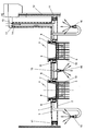
- the accompanying drawing shows a filter head plate according to the invention with two holding devices for filter elements and pointing into the filter chamber nozzles for spraying cleaning liquid.
- the filter head plate consists of a top plate 1 and a bottom plate 2 with an intermediate cavity 3.
- the holding devices 4 consist of an outer holding element 6 and an inner holding element 7.
- the outer holding element 6 is arranged in an opening of the filter head plate and dimensioned so that its height corresponds to the thickness of the filter head plate. It has a passage opening for receiving the inner retaining element 7.
- the passage opening encompassing an inflatable seal 8 is arranged in the outer support member 6, which is so in operative connection with the cavity 3 between the top plate 1 and the bottom plate 2, that upon introduction of a pressurized gas in this cavity 3, the seal 8 is inflated.
- the filter element 5 is arranged, in such a way that the filter element 5 protrudes into the filter chamber when the inner support member 7 is inserted into the passage opening of the outer support member 6.
- the inner holding element 7 has a mating surface 9, which is arranged opposite the inflatable seal 8.
- a filter tube 10 is arranged, the upper edge is located between the inner and outer retaining element 7, 6.
- a gas port 14 is attached, through which a pressurized gas can be introduced into the cavity 3.
- a pressurized gas can be introduced into the cavity 3.
- the seals 8 are inflated, they press the filter tube 10 tightly against the counter surface 9.
- the inner support member 7 is sealed in the outer support member 6 and held so that the filter element 5 is kept sealed in the filter head plate and securely positioned and centered.
- the inner retaining elements 7 are released, so that the filter elements 5 can be removed or replaced.
- this another spanning seal 11 is arranged, which seals the filter head plate relative to the housing 12 of the filter chamber. To this seal 11 performs a separate conduit system 13 for introducing a pressurized gas.
- a conduit system 15 is further arranged, to which in the lower plate 2 directly or via Pipe elements arranged nozzles 16 are connected.
- the nozzles 16 protrude into the filter chamber and are alignable within the filter chamber.
- the line system 15 has a connection 17 arranged above the filter head plate. Through this line system, if necessary, cleaning liquid is conducted to the nozzles 16 and sprayed within the filter chamber.
- the filter head plate with the systems arranged therein for sealing and holding the filter elements 5 and for spraying cleaning fluid in the filter chamber has no structured surface elements on the side facing the filter chamber, has no recesses and has hardly hidden surface elements and undercuts.
- the filter elements 5 can be easily removed or replaced.
- an inflatable seal 11 at the outer edge of the filter head plate allows a tool-free removal of the entire filter head plate.
- the inner walls of the filter chamber have no projections. Both causes a thorough complete cleaning of the filter chamber can be done with little effort and thus with little effort and simple means a residue-free operation of the filter system is possible.
Landscapes
- Chemical & Material Sciences (AREA)
- Chemical Kinetics & Catalysis (AREA)
- Filtering Of Dispersed Particles In Gases (AREA)
Description
- Die Erfindung betrifft eine Filterkopfplatte für einen Filter zur Entstaubung eines Gases, die ein oder mehrere Haltevorrichtungen für ein oder mehrere Filterelemente, wie Filterkerze, Filterpatrone, Filtertasche oder dergleichen sowie ein Flüssigkeitsleitungssystem zur Leitung einer Reinigungsflüssigkeit für die Reinigung der Filterelemente sowie der Filterkammer, aufweist.
- Gattungsgemäße Filterkopfplatten sind beispielsweise in der
DE 43 34 699 , derFR 2 513 539 US 3 849 092 offenbart. - Bekannt sind Filterkopfplatten mit Haltevorrichtungen für Filterelemente, bei denen die Filterelemente über Schraubverbindungen oder mechanische Klemmvorrichtungen z.B. mit Federn und Flanschen gehalten und abgedichtet werden. Derartige Haltevorrichtungen sind meist stark strukturiert und daher aufwendig zu reinigen.
- Bekannt sind ebenfalls an Filterkopfplatten angeordnete Flüssigkeitsleitungssysteme zur Leitung einer Reinigungsflüssigkeit für die Reinigung der Filterelemente sowie der Filterkammer. Die Flüssigkeitsleitungssysteme sind meist als unterhalb der Filterkopfplatte, d.h. in der Filterkammer angeordnete Rohr- oder Schlauchsysteme ausgeführt.
- Derartige Flüssigkeitsleitungssysteme erfordern eine aufwendige Montage der einzelnen Rohr- bzw. Schlauchelemente mit entsprechenden Verbindungselementen und sind aufgrund ihrer stark strukturierten Oberfläche mit vielen verdeckten Flächenelementen, Ausnehmungen, Kanten und Hinterschneidungen ebenfalls nur mit erheblichem Aufwand zu reinigen.
- Der besonders im Food- und Pharmabereich geforderte rückstandsfreie Betrieb einer Filteranlage-erfordert daher einen erheblichen Reinigungsaufwand, verbunden mit langen Stillstandszeiten des Filters.
- Zweck der Erfindung ist die Bereitstellung einer Filterkopfplatte für einen Filter zur Entstaubung eines Gases, die Haltevorrichtungen für ein oder mehrere Filterelemente sowie ein Flüssigkeitsleitungssystem zur Leitung einer Reinigungsflüssigkeit für die Reinigung der Filterelemente sowie der Filterkammer aufweist und nur mit geringem Reinigungsaufwand einen rückstandsfreien Betrieb der Filteranlage ermöglicht. Dazu besteht die Aufgabe, eine Filterkopfplatte zu schaffen, die keine komplizierten in die Filterkammer ragenden Oberflächenstrukturen besitzt.
- Diese Aufgabe wird durch eine Filterkopfplatte gemäß Anspruch 1 gelöst, die aus einer Oberplatte und einer Unterplatte mit zwischenliegenden Hohlraum besteht, wobei in der Filterkopfplatte mindestens eine Haltevorrichtung für ein Filterelement angeordnet ist und diese Haltevorrichtung aus einem äußeren Halteelement und einem inneren Halteelement besteht, wobei das äußere Halteelement in einer Öffnung der Filterkopfplatte angeordnet ist und eine Durchgangsöffnung zur Aufnahme des inneren Halteelementes besitzt. Im äußeren Halteelement ist eine die Durchgangsöffnung umgebende, mit druckbeaufschlagtem Gas aufblasbare Dichtung angeordnet. Das innere, am oberen Ende eines Filterelementes angeordnete Halteelement besitzt an der der Durchgangsöffnung des äußeren Halteelementes zugewandten Seite eine Gegenfläche, an der die aufblasbare Dichtung zur Anlage gebracht werden kann. Das druckbeaufschlagte Gas für das Aufblasen der Dichtung wird im Hohlraum der Filterkopfplatte geführt. Jede aufblasbare Dichtung steht mit dem Hohlraum der Filterkopfplatte so in Wirkverbindung, dass das druckbeaufschlagte Gas in die aufblasbare Dichtung einströmen kann, was zu deren Vergrößerung führt. Dadurch wird die aufblasbare Dichtung gegen die Gegenfläche des inneren Halteelementes gepresst und dichtet, hält und positioniert so das innere Halteelement mit dem daran angeordneten Filterelement im äußeren Halteelement, wodurch letztlich das Filterelement dicht in der Filterkopfplatte gehalten wird. Außerdem ist im Hohlraum der Filterkopfplatte ein Flüssigkeitsleitungssystem angeordnet, mit dem Reinigungsflüssigkeit zu an der Filterkopfplatte angeordneten, in die Filterkammer ragenden Düsen geleitet werden kann.
- Bei einer bevorzugten Ausgestaltung der Erfindung ist der Hohlraum in der Filterkopfplatte zweigeteilt, wobei ein Teilhohlraum zur Leitung des druckbeaufschlagten Gases zu der oder den auflasbaren Dichtungen verwendet wird, während der zweite Teilhohlraum die Reinigungsflüssigkeit führt und diese zu den in die Filterkammer ragenden Düsen leitet. Beide Teilhohlräume besitzen jeweils außerhalb der Filterkammer, bevorzugt in der Oberplatte, angeordnete Anschlusselemente zur Einleitung von druckbeaufschlagtem Gas bzw. Reinigungsflüssigkeit.
- Selbstverständlich kann der Hohlraum zwischen der Oberplatte und der Unterplatte der Filterkopfplatte auch in mehr als zwei Teilhohlräume unterteilt werden, wenn beispielweise ein drittes Medium geführt werden soll oder wenn eine gruppenweise Ansteuerung mehrer aufblasbarer Dichtungen gewünscht ist.
- Dies kann beispielsweise der Fall sein, wenn die Filterkopfplatte selbst mittels einer aufblasbaren Dichtung gegenüber dem Filtergehäuse abgedichtet, positioniert und gehalten wird. Dazu wird an der äußeren, der Gehäusewand der Filterkammer zugewandten Außenkante der Filterkopfplatte eine aufblasbare Dichtung angeordnet, die durch Aufblasen dicht an der Gehäusewand der Filterkammer zur Anlage gebracht wird. Diese aufblasbare Dichtung kann entweder gemeinsam mit den in den Haltevorrichtungen der Filterelemente angeordneten aufblasbaren Dichtungen oder getrennt davon betrieben, d.h. mit druckbeaufschlagtem Gas befüllt oder entleert werden. Eine separate Ansteuerung kann entweder wie vorstehend beschrieben über einen weiteren Teilhohlraum oder über ein separates Leitungssystem erfolgen. Dieses separate Leitungssystem kann im Hohlraum zwischen der Oberplatte und der Unterplatte der Filterkopfplatte angeordnet sein.
- Bei einer anderen bevorzugten Ausgestaltung der Erfindung ist innerhalb des Hohlraumes ein Leitungssystem angeordnet. Wird der Hohlraum zur Leitung des druckbeaufschlagten Gases zu der oder den aufblasbaren Dichtungen verwendet, so dient das innerhalb des Hohlraumes angeordnete Leitungssystem der Leitung der Reinigungsflüssigkeit.
Selbstverständlich ist auch eine umgekehrte Zuordnung des Hohlraumes und des im Hohlraum angeordneten Leitungssystems möglich, nämlich, dass die Reinigungsflüssigkeit im Hohlraum zwischen der Oberplatte und der Unterplatte zu den in die Filterkammer ragenden Düsen geleitet wird und das druckbeaufschlagte Gas mittels des Leitungssystems zu den aufblasbaren Dichtungen geführt wird. - Die in die Filterkammer ragenden Düsen zum Versprühen von Reinigungsflüssigkeit sind bei einer bevorzugten Ausgestaltung der Erfindung ausrichtbar angeordnet. Sie können entweder direkt in der Unterplatte der Filterkopfplatte angeordnet sein oder sich an speziellen richtbaren Schlauch- oder Rohrelementen befinden. Die Ausrichtung der Düsen wird so erfolgen, dass die Reinigungsflüssigkeit sowohl die Filterelemente als auch die Innenwände der Filterkammer benetzt, so dass Staub- und Partikelablagerungen in der Filterkammer gelöst und entfernt werden können.
- Die Ausgestaltung der Filterkopfplatte als doppelwandige Platte mit dazwischenliegendem Hohlraum und der vorstehend beschriebenen Anordnung der Haltevorrichtungen für Filterelemente mit aufblasbaren Dichtungen sowie der Anordnung eines Leitungssystems für Reinigungsflüssigkeit in dem Hohlraum der Filterkopfplatte stelllt eine überraschend einfache und zur Lösung der Aufgabe der Erfindung höchst vorteilhafte Lösung dar. Durch die Erfindung werden stark strukturierte Oberflächen mit vielen verdeckten Flächenelementen, Ausnehmungen, Kanten und Hinterschneidungen in der Filterkammer vermieden. Dadurch kann die Reinigung der Filterkammer besonders einfach und zuverlässig erfolgen.
Die Erfindung soll nachfolgend anhand eines Ausführungsbeispieles weiter beschrieben werden, ohne die Erfindung dadurch einzuschränken. - Die zugehörige Zeichnung zeigt eine erfindungsgemäße Filterkopfplatte mit zwei Haltevorrichtungen für Filterelemente und in die Filterkammer weisende Düsen zum Versprühen von Reinigungsflüssigkeit.
Wie die Figur zeigt, besteht die Filterkopfplatte aus einer Oberplatte 1 und einer Unterplatte 2 mit einem dazwischenliegenden Hohlraum 3. In Öffnungen der Filterkopfplatte sind Haltevorrichtungen 4 für Filterelemente 5 angeordnet. Die Haltevorrichtungen 4 bestehen aus einem äußeren Halteelement 6 und einem inneren Halteelement 7. Das äußere Halteelement 6 ist in einer Öffnung der Filterkopfplatte angeordnet und so bemessen, dass seine Höhe der Dicke der Filterkopfplatte entspricht. Es weist eine Durchgangsöffnung zur Aufnahme des inneren Halteelementes 7 auf. Die Durchgangsöffnung umspannend ist im äußeren Halteelement 6 eine aufblasbare Dichtung 8 angeordnet, die so mit dem Hohlraum 3 zwischen der Oberplatte 1 und der Unterplatte 2 in Wirkverbindung steht, dass bei Einleitung eines druckbeaufschlagten Gases in diesen Hohlraum 3 die Dichtung 8 aufgeblasen wird. Am inneren Halteelement 7 ist das Filterelement 5 angeordnet, und zwar derart, dass das Filterelement 5 in die Filterkammer ragt, wenn das innere Halteelement 7 in die Durchgangsöffnung des äußeren Halteelementes 6 eingesetzt ist. Das innere Halteelement 7 besitzt eine Gegenfläche 9, die gegenüber der aufblasbaren Dichtung 8 angeordnet ist. Um das Filterelement 5 ist ein Filterschlauch 10 angeordnet, dessen oberer Rand sich zwischen innerem und äußerem Halteelement 7, 6 befindet. An der Oberplatte 1 der Filterkopfplatte ist ein Gasanschluss 14 angebracht, durch den ein druckbeaufschlagtes Gas in den Hohlraum 3 eingeleitet werden kann.
Werden die Dichtungen 8 aufgeblasen, drücken sie den Filterschlauch 10 dicht gegen die Gegenfläche 9. Das innere Halteelement 7 wird abgedichtet im äußeren Halteelement 6 gehalten und letztlich so das Filterelement 5 in der Filterkopfplatte abgedichtet gehalten sowie sicher positioniert und zentriert. Bei Druckentlastung der Dichtungen 8 werden die inneren Halteelemente 7 freigegeben, so dass die Filterelemente 5 entnommen bzw. ausgetauscht werden können.
Am äußeren Rand der Filterkopfplatte ist diese umspannend eine weitere aufblasbare Dichtung 11 angeordnet, die die Filterkopfplatte gegenüber dem Gehäuse 12 der Filterkammer abdichtet. Zu dieser Dichtung 11 führt ein separates Leitungssystem 13 zur Einleitung eines druckbeaufschlagten Gases.
Im Hohlraum 3 zwischen der Oberplatte 1 und der Unterplatte 2 ist weiterhin ein Leitungssystem 15 angeordnet, an welches in der Unterplatte 2 direkt oder über Rohrelemente angeordnete Düsen 16 angeschlossen sind. Die Düsen 16 ragen in die Filterkammer und sind innerhalb der Filterkammer ausrichtbar. Das Leitungssystem 15 verfügt über einen oberhalb der Filterkopfplatte angeordneten Anschluss 17. Durch dieses Leitungssystem wird bei Bedarf Reinigungsflüssigkeit zu den Düsen 16 geleitet und innerhalb der Filterkammer versprüht. - Alle Leitungssyteme 13,15 sind mit den zugehörigen Anschlüsse für druckbeaufschlagtes Gas 14 und Reinigungsflüssigkeit 17 an einer Position zusammengeführt. Die Filterkopfplatte mit den darin angeordneten Systemen zur Abdichtung und Halterung der Filterelemente 5 sowie zum Versprühen von Reinigungsflüssigkeit in der Filterkammer weist an der der Filterkammer zugewandten Seite keine strukturierten Flächenelemente auf, besitzt keine Ausnehmungen und weist kaum verdeckte Flächenelemente und Hinterschneidungen auf.
- Die Filterelemente 5 können unproblematisch entnommen bzw. ausgetauscht werden.
- Darüber hinaus ermöglicht die erfindungsgemäße Anordnung einer aufblasbaren Dichtung 11 am äußeren rand der Filterkopfplatte eine werkzeugfreie Entnahme der kompletten Filterkopfplatte. Die Innenwände der Filterkammer weisen keine Vorsprünge auf. Beides bewirkt, dass eine gründliche Komplettreinigung der Filterkammer mit geringem Aufwand erfolgen kann und so mit geringem Aufwand und einfachen Mitteln ein rückstandsfreier Betrieb der Filteranlage ermöglicht wird.
-
- 1
- Oberplatte
- 2
- Unterplatte
- 3
- Hohlraum
- 4
- Haltevorrichtung
- 5
- Filterelement
- 6
- äußeres Halteelement
- 7
- inneres Halteelement
- 8
- aufblasbare Dichtung
- 9
- Gegenfläche
- 10
- Filterschlauch
- 11
- Dichtung
- 12
- Gehäuse
- 13
- Leitungssystem
- 14
- Gasanschluss
- 15
- Leitungssystem
- 16
- Düse
- 17
- Anschluss
Claims (6)
- Filterkopfplatte für einen Filter zur Entstaubung eines Gases, bestehend aus einer Oberplatte (1) und einer Unterplatte (2) mit einem zwischenliegenden Hohlraum (3), mindestens einer Haltevorrichtung (4) für mindestens einen Filterschlauch (10), wobei die Haltevorrichtung (4) aus einem am offenen Ende des Filterschlauches (10), dessen Öffnung an der radialen Innenseite des Filterschlauchs (10) umgebend angeordneten inneren Halteelement (7) mit einer radial nach außen weisenden Gegenfläche (9), einem äußeren Halteelement (6) mit einer Durchgangsöffnung zur Aufnahme des inneren Halteelementes (7) und einer zwischen beiden Halteelementen (6, 7) angeordneten mit druckbeaufschlagtem Gas aufblasbaren Dichtung (8) besteht, wobei der Filterschlauch (10) zwischen dem inneren Halteelement (7) und dem äußeren Haltelement (6) platziert ist und die aufblasbare Dichtung (8) den Filterschlauch (10) gegen die Gegenfläche (9) drückt, einem Leitungssystem zur Leitung eines druckbeaufschlagten Gases zur aufblasbaren Dichtung (8) und einem Flüssigkeitsleitungssystem (15) zur Leitung einer Reinigungsflüssigkeit für die Reinigung des Filterschlauches (10),
dadurch gekennzeichnet, dass
das äußere Halteelement (6) in einer die Oberplatte (1) und die Unterplatte (2) der Filterkopfplatte durchgreifenden Öffnung angeordnet ist, so dass die Durchgangsöffnung des äußeren Halteelementes (6) eine Durchgangsöffnung durch die Filterkopfplatte bildet, die aufblasbare Dichtung (8) am äußeren Halteelement (6) die Durchgangsöffnung umgebend angeordnet ist und eine Verbindung zu dem zur Leitung des druckbeaufschlagten Gases ausgebildeten Hohlraum (3) besitzt und das Flüssigkeitsleitungssystem (15) zur Leitung einer Reinigungsflüssigkeit im Hohlraum (3) der Filterkopfplatte angeordnet ist. - Filterkopfplatte nach Anspruch 1,
dadurch gekennzeichnet, dass
der Hohlraum (3) zwischen der Oberplatte (1) und der Unterplatte (2) der Filterkopfplatte zweigeteilt ausgeführt ist, wobei jeder Teilhohlraum ein äußeres Anschlusselement aufweist und ein Teilhohlraum mit den in den äußeren Halteelementen (6) angeordneten auflasbaren Dichtungen (8) verbunden ist, während der andere Teilhohlraum mit in die Filterkammer ragenden Düsen (16) zum Versprühen der Reinigungsflüssigkeit verbunden ist. - Filterkopfplatte nach Anspruch 1,
dadurch gekennzeichnet, dass
der Hohlraum (3) mit in die Filterkammer ragenden Düsen (16) zum Versprühen der Reinigungsflüssigkeit verbunden ist und dass im Hohlraum (3) ein Leitungssystem zur Leitung des druckbeaufschlagten Gases zu den in den äußeren Halteelementen (6) angeordneten aufblasbaren Dichtungen (8) angeordnet ist. - Filterkopfplatte nach einem der vorgenannten Ansprüche,
dadurch gekennzeichnet, dass
an der äußeren, der Gehäusewand (12) der Filterkammer zugewandten Außenkante der Filterkopfplatte eine aufblasbare Dichtung (11) angeordnet ist, die durch Aufblasen dicht an der Gehäusewand (12) der Filterkammer zur Anlage gebracht werden kann. - Filterkopfplatte nach Anspruch 4,
dadurch gekennzeichnet, dass
die an derAußenkante der Filterkopfplatte angeordnete aufblasbare Dichtung (11) zwischen der Oberplatte (1) und der Unterplatte (2) der Filterkopfplatte angeordnet ist und mit dem das druckbeaufschlagte Gas führenden Hohlraum (3) der Filterkopfplatte oder einem Leitungssytem (13) verbunden ist. - Filterkopfplatte nach einem der vorgenannten Ansprüche,
dadurch gekennzeichnet, dass
die Düsen (16) zum Versprühen der Reinigungsflüssigkeit ausrichtbar angeordnet sind.
Applications Claiming Priority (2)
| Application Number | Priority Date | Filing Date | Title |
|---|---|---|---|
| DE102007016037A DE102007016037A1 (de) | 2007-03-26 | 2007-03-26 | Filterkopfplatte mit Halte- und/oder Spülsystem |
| PCT/DE2008/000503 WO2008128498A2 (de) | 2007-03-26 | 2008-03-25 | Filterkopfplatte |
Publications (2)
| Publication Number | Publication Date |
|---|---|
| EP2129447A2 EP2129447A2 (de) | 2009-12-09 |
| EP2129447B1 true EP2129447B1 (de) | 2016-10-05 |
Family
ID=39596355
Family Applications (1)
| Application Number | Title | Priority Date | Filing Date |
|---|---|---|---|
| EP08734433.9A Active EP2129447B1 (de) | 2007-03-26 | 2008-03-25 | Filterkopfplatte |
Country Status (3)
| Country | Link |
|---|---|
| EP (1) | EP2129447B1 (de) |
| DE (2) | DE102007016037A1 (de) |
| WO (1) | WO2008128498A2 (de) |
Families Citing this family (2)
| Publication number | Priority date | Publication date | Assignee | Title |
|---|---|---|---|---|
| PL2888023T3 (pl) * | 2012-08-22 | 2019-09-30 | Mann+Hummel Gmbh | Urządzenie filtracyjne, zwłaszcza do filtracji gazu |
| DE102013004241B4 (de) * | 2013-03-12 | 2017-01-12 | Riedel Filtertechnik Gmbh | Filtervorrichtung |
Family Cites Families (3)
| Publication number | Priority date | Publication date | Assignee | Title |
|---|---|---|---|---|
| US3849092A (en) * | 1972-03-31 | 1974-11-19 | Slick Corp | Apparatus for separating a gaseous carrier from particulate matter entrained therein |
| FR2513539A1 (fr) * | 1981-09-28 | 1983-04-01 | Neu Ets | Dispositif depoussiereur filtrant a decolmatage pneumatique |
| DE4334699C1 (de) * | 1993-10-12 | 1994-11-17 | Margraf Adolf | Filternder Abscheider |
-
2007
- 2007-03-26 DE DE102007016037A patent/DE102007016037A1/de not_active Withdrawn
-
2008
- 2008-03-25 DE DE112008001398T patent/DE112008001398A5/de not_active Withdrawn
- 2008-03-25 EP EP08734433.9A patent/EP2129447B1/de active Active
- 2008-03-25 WO PCT/DE2008/000503 patent/WO2008128498A2/de not_active Ceased
Also Published As
| Publication number | Publication date |
|---|---|
| DE112008001398A5 (de) | 2010-02-25 |
| WO2008128498A2 (de) | 2008-10-30 |
| EP2129447A2 (de) | 2009-12-09 |
| DE102007016037A1 (de) | 2008-10-02 |
| WO2008128498A3 (de) | 2008-12-11 |
Similar Documents
| Publication | Publication Date | Title |
|---|---|---|
| DE2403166C2 (de) | Apparat zur Behandlung von Flüssigkeiten | |
| DE3005146C2 (de) | Druckgasanschluß bei Staubgasfiltern | |
| CH629673A5 (en) | Filter | |
| EP2129447B1 (de) | Filterkopfplatte | |
| EP0369147A2 (de) | Dichtung für feuerfeste, metallische Schmelze führende Bauteile | |
| DE10224634C2 (de) | Vorrichtung zum Filtern von unter einem hohen Druck geförderten Fluiden | |
| EP3707450B1 (de) | Absperrschieber | |
| WO2008058597A1 (de) | Kupplungsvorrichtung | |
| DE2335915C3 (de) | Einrichtung zur Halterung und Verbindung von in Reihe geschalteten Vorrichtungen zum Steuern und/oder Konditionieren für Fluide | |
| EP2066423B1 (de) | Anordnung zum verschliessen eines endabschnittes eines rohres oder eines rohrförmigen behältnisses | |
| DE2618234C3 (de) | Filter mit auswechselbarem Filtereinsatz | |
| DE3227545A1 (de) | Hochdruckautoklav | |
| DE2107987A1 (de) | Kupplung fur Vielfachrohrleitungen | |
| EP2129446B1 (de) | Haltevorrichtung mit Filterschlauch | |
| DE10144509C1 (de) | Ölbeseitigungsvorrichtung zum Reinigen von in Form von Coils vorliegenden Rohren | |
| DE2634547C3 (de) | Einrichtung an einem Flüssigkeitstank, insbesondere an einem Biertank | |
| EP0607403A1 (de) | Filterapparat. | |
| DE3106790C2 (de) | Einrichtung zum Abschirmen eines Offenbereiches zwischen einem Industrieofen, insbesondere Konverter, und einem Ofenkamin mittels eines Sperrgasvorhanges | |
| EP3642521A1 (de) | Anschlusskopf und ventilknoten | |
| DE2443295C3 (de) | Druckbehälter für einen Dampfschäler | |
| DE4110186C2 (de) | ||
| DE1238053B (de) | Waermetauscher mit einem durch das Mantelrohr schiebbaren Rohrboden | |
| DE102017100583A1 (de) | Reinigungsvorrichtung für ein Staubfilter | |
| DE1908093C (de) | Schnell betatigbare Kupplung fur Rohre, Schlauche u dgl | |
| DE102008048589A1 (de) | Feinstaubfilter mit Druckstoßabreinigung |
Legal Events
| Date | Code | Title | Description |
|---|---|---|---|
| PUAI | Public reference made under article 153(3) epc to a published international application that has entered the european phase |
Free format text: ORIGINAL CODE: 0009012 |
|
| 17P | Request for examination filed |
Effective date: 20091021 |
|
| AK | Designated contracting states |
Kind code of ref document: A2 Designated state(s): AT BE BG CH CY CZ DE DK EE ES FI FR GB GR HR HU IE IS IT LI LT LU LV MC MT NL NO PL PT RO SE SI SK TR |
|
| DAX | Request for extension of the european patent (deleted) | ||
| 17Q | First examination report despatched |
Effective date: 20140703 |
|
| GRAP | Despatch of communication of intention to grant a patent |
Free format text: ORIGINAL CODE: EPIDOSNIGR1 |
|
| INTG | Intention to grant announced |
Effective date: 20160425 |
|
| GRAS | Grant fee paid |
Free format text: ORIGINAL CODE: EPIDOSNIGR3 |
|
| GRAA | (expected) grant |
Free format text: ORIGINAL CODE: 0009210 |
|
| RAP1 | Party data changed (applicant data changed or rights of an application transferred) |
Owner name: PERGANDE GESELLSCHAFT FUER INDUSTRIELLE ENTSTAUBUN |
|
| AK | Designated contracting states |
Kind code of ref document: B1 Designated state(s): AT BE BG CH CY CZ DE DK EE ES FI FR GB GR HR HU IE IS IT LI LT LU LV MC MT NL NO PL PT RO SE SI SK TR |
|
| REG | Reference to a national code |
Ref country code: GB Ref legal event code: FG4D Free format text: NOT ENGLISH |
|
| REG | Reference to a national code |
Ref country code: CH Ref legal event code: EP |
|
| REG | Reference to a national code |
Ref country code: AT Ref legal event code: REF Ref document number: 834130 Country of ref document: AT Kind code of ref document: T Effective date: 20161015 |
|
| REG | Reference to a national code |
Ref country code: IE Ref legal event code: FG4D Free format text: LANGUAGE OF EP DOCUMENT: GERMAN |
|
| REG | Reference to a national code |
Ref country code: DE Ref legal event code: R096 Ref document number: 502008014683 Country of ref document: DE |
|
| REG | Reference to a national code |
Ref country code: NL Ref legal event code: MP Effective date: 20161005 |
|
| REG | Reference to a national code |
Ref country code: LT Ref legal event code: MG4D |
|
| PG25 | Lapsed in a contracting state [announced via postgrant information from national office to epo] |
Ref country code: LV Free format text: LAPSE BECAUSE OF FAILURE TO SUBMIT A TRANSLATION OF THE DESCRIPTION OR TO PAY THE FEE WITHIN THE PRESCRIBED TIME-LIMIT Effective date: 20161005 |
|
| PG25 | Lapsed in a contracting state [announced via postgrant information from national office to epo] |
Ref country code: GR Free format text: LAPSE BECAUSE OF FAILURE TO SUBMIT A TRANSLATION OF THE DESCRIPTION OR TO PAY THE FEE WITHIN THE PRESCRIBED TIME-LIMIT Effective date: 20170106 Ref country code: SE Free format text: LAPSE BECAUSE OF FAILURE TO SUBMIT A TRANSLATION OF THE DESCRIPTION OR TO PAY THE FEE WITHIN THE PRESCRIBED TIME-LIMIT Effective date: 20161005 Ref country code: NO Free format text: LAPSE BECAUSE OF FAILURE TO SUBMIT A TRANSLATION OF THE DESCRIPTION OR TO PAY THE FEE WITHIN THE PRESCRIBED TIME-LIMIT Effective date: 20170105 Ref country code: LT Free format text: LAPSE BECAUSE OF FAILURE TO SUBMIT A TRANSLATION OF THE DESCRIPTION OR TO PAY THE FEE WITHIN THE PRESCRIBED TIME-LIMIT Effective date: 20161005 |
|
| PG25 | Lapsed in a contracting state [announced via postgrant information from national office to epo] |
Ref country code: IS Free format text: LAPSE BECAUSE OF FAILURE TO SUBMIT A TRANSLATION OF THE DESCRIPTION OR TO PAY THE FEE WITHIN THE PRESCRIBED TIME-LIMIT Effective date: 20170205 Ref country code: NL Free format text: LAPSE BECAUSE OF FAILURE TO SUBMIT A TRANSLATION OF THE DESCRIPTION OR TO PAY THE FEE WITHIN THE PRESCRIBED TIME-LIMIT Effective date: 20161005 Ref country code: FI Free format text: LAPSE BECAUSE OF FAILURE TO SUBMIT A TRANSLATION OF THE DESCRIPTION OR TO PAY THE FEE WITHIN THE PRESCRIBED TIME-LIMIT Effective date: 20161005 Ref country code: HR Free format text: LAPSE BECAUSE OF FAILURE TO SUBMIT A TRANSLATION OF THE DESCRIPTION OR TO PAY THE FEE WITHIN THE PRESCRIBED TIME-LIMIT Effective date: 20161005 Ref country code: PL Free format text: LAPSE BECAUSE OF FAILURE TO SUBMIT A TRANSLATION OF THE DESCRIPTION OR TO PAY THE FEE WITHIN THE PRESCRIBED TIME-LIMIT Effective date: 20161005 Ref country code: ES Free format text: LAPSE BECAUSE OF FAILURE TO SUBMIT A TRANSLATION OF THE DESCRIPTION OR TO PAY THE FEE WITHIN THE PRESCRIBED TIME-LIMIT Effective date: 20161005 Ref country code: PT Free format text: LAPSE BECAUSE OF FAILURE TO SUBMIT A TRANSLATION OF THE DESCRIPTION OR TO PAY THE FEE WITHIN THE PRESCRIBED TIME-LIMIT Effective date: 20170206 |
|
| REG | Reference to a national code |
Ref country code: DE Ref legal event code: R097 Ref document number: 502008014683 Country of ref document: DE |
|
| PG25 | Lapsed in a contracting state [announced via postgrant information from national office to epo] |
Ref country code: EE Free format text: LAPSE BECAUSE OF FAILURE TO SUBMIT A TRANSLATION OF THE DESCRIPTION OR TO PAY THE FEE WITHIN THE PRESCRIBED TIME-LIMIT Effective date: 20161005 Ref country code: CZ Free format text: LAPSE BECAUSE OF FAILURE TO SUBMIT A TRANSLATION OF THE DESCRIPTION OR TO PAY THE FEE WITHIN THE PRESCRIBED TIME-LIMIT Effective date: 20161005 Ref country code: RO Free format text: LAPSE BECAUSE OF FAILURE TO SUBMIT A TRANSLATION OF THE DESCRIPTION OR TO PAY THE FEE WITHIN THE PRESCRIBED TIME-LIMIT Effective date: 20161005 Ref country code: DK Free format text: LAPSE BECAUSE OF FAILURE TO SUBMIT A TRANSLATION OF THE DESCRIPTION OR TO PAY THE FEE WITHIN THE PRESCRIBED TIME-LIMIT Effective date: 20161005 Ref country code: SK Free format text: LAPSE BECAUSE OF FAILURE TO SUBMIT A TRANSLATION OF THE DESCRIPTION OR TO PAY THE FEE WITHIN THE PRESCRIBED TIME-LIMIT Effective date: 20161005 |
|
| PLBE | No opposition filed within time limit |
Free format text: ORIGINAL CODE: 0009261 |
|
| STAA | Information on the status of an ep patent application or granted ep patent |
Free format text: STATUS: NO OPPOSITION FILED WITHIN TIME LIMIT |
|
| PG25 | Lapsed in a contracting state [announced via postgrant information from national office to epo] |
Ref country code: IT Free format text: LAPSE BECAUSE OF FAILURE TO SUBMIT A TRANSLATION OF THE DESCRIPTION OR TO PAY THE FEE WITHIN THE PRESCRIBED TIME-LIMIT Effective date: 20161005 Ref country code: BG Free format text: LAPSE BECAUSE OF FAILURE TO SUBMIT A TRANSLATION OF THE DESCRIPTION OR TO PAY THE FEE WITHIN THE PRESCRIBED TIME-LIMIT Effective date: 20170105 |
|
| 26N | No opposition filed |
Effective date: 20170706 |
|
| REG | Reference to a national code |
Ref country code: CH Ref legal event code: PL |
|
| GBPC | Gb: european patent ceased through non-payment of renewal fee |
Effective date: 20170325 |
|
| PG25 | Lapsed in a contracting state [announced via postgrant information from national office to epo] |
Ref country code: SI Free format text: LAPSE BECAUSE OF FAILURE TO SUBMIT A TRANSLATION OF THE DESCRIPTION OR TO PAY THE FEE WITHIN THE PRESCRIBED TIME-LIMIT Effective date: 20161005 Ref country code: MC Free format text: LAPSE BECAUSE OF FAILURE TO SUBMIT A TRANSLATION OF THE DESCRIPTION OR TO PAY THE FEE WITHIN THE PRESCRIBED TIME-LIMIT Effective date: 20161005 |
|
| REG | Reference to a national code |
Ref country code: IE Ref legal event code: MM4A |
|
| REG | Reference to a national code |
Ref country code: FR Ref legal event code: ST Effective date: 20171130 |
|
| PG25 | Lapsed in a contracting state [announced via postgrant information from national office to epo] |
Ref country code: FR Free format text: LAPSE BECAUSE OF NON-PAYMENT OF DUE FEES Effective date: 20170331 Ref country code: LU Free format text: LAPSE BECAUSE OF NON-PAYMENT OF DUE FEES Effective date: 20170325 |
|
| PG25 | Lapsed in a contracting state [announced via postgrant information from national office to epo] |
Ref country code: IE Free format text: LAPSE BECAUSE OF NON-PAYMENT OF DUE FEES Effective date: 20170325 Ref country code: CH Free format text: LAPSE BECAUSE OF NON-PAYMENT OF DUE FEES Effective date: 20170331 Ref country code: LI Free format text: LAPSE BECAUSE OF NON-PAYMENT OF DUE FEES Effective date: 20170331 Ref country code: GB Free format text: LAPSE BECAUSE OF NON-PAYMENT OF DUE FEES Effective date: 20170325 |
|
| REG | Reference to a national code |
Ref country code: BE Ref legal event code: MM Effective date: 20170331 |
|
| REG | Reference to a national code |
Ref country code: AT Ref legal event code: MM01 Ref document number: 834130 Country of ref document: AT Kind code of ref document: T Effective date: 20170325 |
|
| PG25 | Lapsed in a contracting state [announced via postgrant information from national office to epo] |
Ref country code: BE Free format text: LAPSE BECAUSE OF NON-PAYMENT OF DUE FEES Effective date: 20170331 |
|
| PG25 | Lapsed in a contracting state [announced via postgrant information from national office to epo] |
Ref country code: AT Free format text: LAPSE BECAUSE OF NON-PAYMENT OF DUE FEES Effective date: 20170325 |
|
| PG25 | Lapsed in a contracting state [announced via postgrant information from national office to epo] |
Ref country code: MT Free format text: LAPSE BECAUSE OF FAILURE TO SUBMIT A TRANSLATION OF THE DESCRIPTION OR TO PAY THE FEE WITHIN THE PRESCRIBED TIME-LIMIT Effective date: 20161005 |
|
| PG25 | Lapsed in a contracting state [announced via postgrant information from national office to epo] |
Ref country code: HU Free format text: LAPSE BECAUSE OF FAILURE TO SUBMIT A TRANSLATION OF THE DESCRIPTION OR TO PAY THE FEE WITHIN THE PRESCRIBED TIME-LIMIT; INVALID AB INITIO Effective date: 20080325 |
|
| PG25 | Lapsed in a contracting state [announced via postgrant information from national office to epo] |
Ref country code: CY Free format text: LAPSE BECAUSE OF NON-PAYMENT OF DUE FEES Effective date: 20161005 |
|
| PG25 | Lapsed in a contracting state [announced via postgrant information from national office to epo] |
Ref country code: TR Free format text: LAPSE BECAUSE OF FAILURE TO SUBMIT A TRANSLATION OF THE DESCRIPTION OR TO PAY THE FEE WITHIN THE PRESCRIBED TIME-LIMIT Effective date: 20161005 |
|
| P01 | Opt-out of the competence of the unified patent court (upc) registered |
Effective date: 20231010 |
|
| PGFP | Annual fee paid to national office [announced via postgrant information from national office to epo] |
Ref country code: DE Payment date: 20250225 Year of fee payment: 18 |