EP2129139A1 - Dispositif de station de base et procédé de commande de communication - Google Patents
Dispositif de station de base et procédé de commande de communication Download PDFInfo
- Publication number
- EP2129139A1 EP2129139A1 EP08711761A EP08711761A EP2129139A1 EP 2129139 A1 EP2129139 A1 EP 2129139A1 EP 08711761 A EP08711761 A EP 08711761A EP 08711761 A EP08711761 A EP 08711761A EP 2129139 A1 EP2129139 A1 EP 2129139A1
- Authority
- EP
- European Patent Office
- Prior art keywords
- user equipment
- transmission power
- control channel
- channel
- control
- Prior art date
- Legal status (The legal status is an assumption and is not a legal conclusion. Google has not performed a legal analysis and makes no representation as to the accuracy of the status listed.)
- Withdrawn
Links
Images


Classifications
-
- H—ELECTRICITY
- H04—ELECTRIC COMMUNICATION TECHNIQUE
- H04W—WIRELESS COMMUNICATION NETWORKS
- H04W72/00—Local resource management
- H04W72/50—Allocation or scheduling criteria for wireless resources
- H04W72/56—Allocation or scheduling criteria for wireless resources based on priority criteria
-
- H—ELECTRICITY
- H04—ELECTRIC COMMUNICATION TECHNIQUE
- H04W—WIRELESS COMMUNICATION NETWORKS
- H04W52/00—Power management, e.g. TPC [Transmission Power Control], power saving or power classes
- H04W52/04—TPC
- H04W52/30—TPC using constraints in the total amount of available transmission power
- H04W52/34—TPC management, i.e. sharing limited amount of power among users or channels or data types, e.g. cell loading
-
- H—ELECTRICITY
- H04—ELECTRIC COMMUNICATION TECHNIQUE
- H04L—TRANSMISSION OF DIGITAL INFORMATION, e.g. TELEGRAPHIC COMMUNICATION
- H04L5/00—Arrangements affording multiple use of the transmission path
- H04L5/003—Arrangements for allocating sub-channels of the transmission path
- H04L5/0037—Inter-user or inter-terminal allocation
-
- H—ELECTRICITY
- H04—ELECTRIC COMMUNICATION TECHNIQUE
- H04L—TRANSMISSION OF DIGITAL INFORMATION, e.g. TELEGRAPHIC COMMUNICATION
- H04L5/00—Arrangements affording multiple use of the transmission path
- H04L5/003—Arrangements for allocating sub-channels of the transmission path
- H04L5/0053—Allocation of signaling, i.e. of overhead other than pilot signals
-
- H—ELECTRICITY
- H04—ELECTRIC COMMUNICATION TECHNIQUE
- H04W—WIRELESS COMMUNICATION NETWORKS
- H04W52/00—Power management, e.g. TPC [Transmission Power Control], power saving or power classes
- H04W52/04—TPC
- H04W52/30—TPC using constraints in the total amount of available transmission power
- H04W52/32—TPC of broadcast or control channels
-
- H—ELECTRICITY
- H04—ELECTRIC COMMUNICATION TECHNIQUE
- H04W—WIRELESS COMMUNICATION NETWORKS
- H04W72/00—Local resource management
- H04W72/50—Allocation or scheduling criteria for wireless resources
- H04W72/56—Allocation or scheduling criteria for wireless resources based on priority criteria
- H04W72/566—Allocation or scheduling criteria for wireless resources based on priority criteria of the information or information source or recipient
-
- H—ELECTRICITY
- H04—ELECTRIC COMMUNICATION TECHNIQUE
- H04W—WIRELESS COMMUNICATION NETWORKS
- H04W88/00—Devices specially adapted for wireless communication networks, e.g. terminals, base stations or access point devices
- H04W88/08—Access point devices
-
- H—ELECTRICITY
- H04—ELECTRIC COMMUNICATION TECHNIQUE
- H04L—TRANSMISSION OF DIGITAL INFORMATION, e.g. TELEGRAPHIC COMMUNICATION
- H04L5/00—Arrangements affording multiple use of the transmission path
- H04L5/0001—Arrangements for dividing the transmission path
- H04L5/0003—Two-dimensional division
- H04L5/0005—Time-frequency
- H04L5/0007—Time-frequency the frequencies being orthogonal, e.g. OFDM(A), DMT
Definitions
- the present invention generally relates to a mobile communication system employing an Orthogonal Frequency Division Multiplexing (OFDM) scheme, and more particularly to a base station apparatus and a communication control method.
- OFDM Orthogonal Frequency Division Multiplexing
- an LTE system As a next-generation system of the W-CDMA (Wideband Code Division Multiple Access) and the HSDPA (High Speed Downlink Packet Access), an LTE system has been studied by 3GPP (3 rd Generation Partnership Project) which is a standards body of the W-CDMA.
- 3GPP 3 rd Generation Partnership Project
- an OFDM (Orthogonal Frequency Division Multiplexing) scheme and an SC-FDMA (Single-Carrier Frequency Division Multiple Access) scheme have been studied to be applied to the downlink communications system and the uplink communication system, respectively (see, for example, Non Patent Document 1).
- a frequency band is divided into plural sub-carriers having narrower frequency bands, and data are transmitted on each sub frequency band and the sub-carriers are closely arranged so as not to interfere with each other, so that fast data transmission can be achieved and an efficiency use of the frequency band can be improved.
- a frequency band is divided in a manner so that different frequencies can be separately used among plural terminals (user equipment terminals) and as a result, interferences between terminals can be reduced. Further, in the SC-FDMA scheme, a range of transmission power fluctuation can be made smaller; therefore lower energy consumption of terminals can be achieved and a wider coverage area can be obtained.
- communications are performed by sharing one or more physical channels among plural mobile stations (user equipment (UE) terminals).
- the channel shared among plural mobile terminals is generally called a shared channel.
- a Physical Uplink Shared Channel (PUSCH) and a Physical Downlink Shared Channel (PDSCH) are the shared channels in uplink and downlink, respectively.
- the transport channels (TrCH) to be mapped over the PUSCH and PDSCH are an Uplink-Shared Channel (UL-SCH) and a Downlink-Shared Channel (DL-SCH), respectively.
- the channel used for the signaling is called a Physical Downlink Control Channel (PDCCH) or Downlink L1/L2 Control Channel (DL L1/L2 Control channel).
- the information items of the Physical Downlink Control Channel (PDCCH) includes, for example, a DL L1/L2 Control Channel Format Indicator, DL (Downlink) Scheduling Information, Acknowledgement information (UL ACK/NACK), Uplink Scheduling Grant, an Overload Indicator, and a Transmission Power Control Command Bit (TPC bit) (see Non Patent Document 2).
- the DL L1/L2 Control Format Indicator may also be called a Physical Control Format Indicator Channel (PCFICH), and the UL ACK/NACK may also be called a Physical Hybrid ARQ Indicator Channel (PHICH).
- PCFICH Physical Control Format Indicator Channel
- PHICH Physical Hybrid ARQ Indicator Channel
- the PCFICH and the PHICH are not necessarily included in the PDCCH and may be defined as separate physical channels having a parallel relationship with the Physical Downlink Control Channel (PDCCH).
- the DL Scheduling Information includes, for example, allocation information of downlink resource blocks, an ID of user equipment (UE) (hereinafter may be referred to as a user equipment (UE) terminal), the number of streams, information of a Precoding Vector, data size, a modulation scheme, and information of HARQ (Hybrid Automatic Repeat reQuest).
- the DL Scheduling Information may also be called DL Assignment Information or DL Scheduling Grant.
- the UL Scheduling Grant includes, for example, allocation information of uplink resource blocks, the ID of user equipment (UE), the data size, the modulation scheme, power information of the uplink transmission, and information of a Demodulation Reference Signal.
- the Transmission power control is applied to each of the information items transmitted in the Physical Downlink Control Channel (PDCCH) in the LTE system, as described above, the information items including the DL L1/L2 Control Channel Format Indicator, the Downlink Scheduling Information, the Acknowledgement information (UL ACK/NACK), the Uplink Scheduling Grant, the Overload Indicator, and the Transmission Power Control Command Bit (TPC bit).
- the Downlink Scheduling Information indicates identification information of the user equipment communicating using a shared channel in the sub-frame in downlink and a transmission format of the shared channel.
- the Uplink Scheduling Grant indicates identification information of the user equipment communicating using a shared channel in a predetermined sub-frame in uplink and a transmission format of the shared channel.
- the shared channel may not be transmitted and as a result, the communications quality may be degraded.
- the user equipment may not be able to correctly decode the identification information of the user equipment communicating using the shared channel in the sub-frame and the information indicating the transmission format of the shared channel, and as a result, the communications using the shared channel may not be performed.
- the transmission power control may be necessary to perform the transmission power control by taking into consideration the communications quality (e.g., an error rate) of the identification information of the user equipment communicating using the shared channel in the sub-frame and the information indicating the transmission format of the shared channel.
- the communications quality e.g., an error rate
- the present invention may provide a base station apparatus and a communication control method capable of adequately performing the transmission power control of the identification information of the user equipment communicating using the shared channel in the sub-frame and the information indicating the transmission format of the shared channel.
- a base station apparatus capable of communicating with a plurality of user equipment terminals using a shared channel.
- the base station apparatus includes a selection unit selecting user equipment terminals to which radio resources are allocated based on priority levels indicating a priority order of allocating the radio resources for the shared channel; and a resource determination unit determining a transmission power of a control channel and resources for the control channel, the control channel indicating communications of the shared channel to the selected user equipment terminals.
- the resource determination unit transmits the control channel to some user equipment terminals among the selected user equipment terminals.
- a base station apparatus capable of communicating with a plurality of user equipment terminals using a shared channel in uplink and downlink and transmitting a control signal in downlink for the shared channel in uplink and downlink.
- the base station apparatus includes a transmission power calculation unit calculating a transmission power of the control signal; a resource element number counting unit counting a number of resource elements for the control signal; and an OFDM symbol number determination unit determining a number of OFDM symbols for the control signal based on the transmission power and the number of resource elements.
- a communication control method employed in a base station apparatus capable of communicating with a plurality of user equipment terminals using a shared channel.
- the method includes a first selection step of selecting user equipment terminals to which radio resources are allocated based on priority levels indicating a priority order of allocating the radio resources for the shared channel; a determination step of determining a transmission power of a control channel and resources for the control channel, the control channel indicating communications of the shared channel to the selected user equipment terminals; a second selection step of selecting user equipment terminals to which the radio resources are allocated based on the priority levels indicating the priority order of allocating the radio resources; and a transmission power control step of controlling a transmission power of a control channel to the selected user equipment terminals.
- the control channel is transmitted to some user equipment terminals among the selected user equipment terminals.
- a base station apparatus and a communication control method capable of adequately performing the transmission power control of the identification information of the user equipment communicating using the sub-frame of the shared channel and the information indicating the transmission format of the shared channel.
- the radio communication system 1000 which may be an Evolved UTRA (Universal Terrestrial Radio Access) and UTRAN (UTRA Network) system (a.k.a an LTE (Long Term Evolution) system or a super 3G system), includes a base station apparatus (eNB: eNode B) 200 and plural user equipment (UE) 100 n (100 1 , 100 2 , 100 3 , ... 100 n ; n: an integer greater than zero (0)) (hereinafter, the user equipment (UE) may be referred to as a user equipment terminal(s)).
- the base station apparatus 200 is connected to an upper node station such as an access gateway 300.
- the access gateway 300 is connected to a core network 400.
- the user equipment (UE) terminals 100 n are in communication with the base station apparatus 200 in a cell 50 using the Evolved UTRA and UTRAN radio communication scheme.
- Each of the user equipment terminals (100 1 , 100 2 , 100 3 , ... 100 n ) has the same configuration, functions, and status. Therefore, in the following, unless otherwise described, the term user equipment (UE) 100 n may be collectively used in the following descriptions.
- the term user equipment (UE) is used as a terminal to be in wireless communication with the base station apparatus.
- a mobile terminal and a fixed terminal may also be applied to such a device.
- the OFDM (Orthogonal Frequency Division Multiplexing) scheme and the SC-FDMA (Single-Carrier Frequency Division Multiplexing Access) scheme are used in downlink and uplink communications, respectively.
- the OFDM scheme is a multi-carrier transmission scheme in which a frequency band is divided into plural sub-carriers having narrow frequency bands and data are mapped on each sub-carrier to be transmitted.
- the SC-FDMA scheme is a single-carrier transmission scheme in which a frequency band is divided so that different frequencies can be used among plural terminals and as a result, interferences between terminals can be reduced.
- a Physical Downlink Shared Channel (PDSCH) shared among the user equipment terminals 100 n and a Physical Downlink Control Channel (PDCCH) are used.
- the Physical Downlink Control Channel (PDCCH) may also be called a Downlink L1/L2 Control Channel (DL L1/L2 Control Channel).
- User data (i.e. a normal data signal) are transmitted via the Physical Downlink Shared Channel (PDSCH).
- DL L1/L2 Control Channel Format Indicator Downlink Scheduling Information
- UL ACK/NACK Uplink Scheduling Grant
- TPC bit Transmission Power Control Command Bit
- the DL Scheduling Information may also be called DL Assignment Information or DL Scheduling Grant.
- the DL L1/L2 Control Format Indicator may also be called a Physical Control Format Indicator Channel (PCFICH).
- the UL ACK/NACK may also be called a Physical Hybrid ARQ Indicator Channel (PHICH).
- the PCFICH, the PHICH, and the Transmission Power Control Command Bit are defined to be included in the PDCCH.
- the PCFICH, the PHICH, and the Transmission Power Control Command Bit may be defined as separate physical channels having a parallel relationship with the PDCCH.
- the DL Scheduling Information includes, for example, information indicating the identification (ID) of the user equipment to communicate using the Physical Downlink Shared Channel (PDSCH); information items indicating the transport format of the user data, namely information items indicating the data size, and the modulation scheme; information of HARQ (Hybrid Automatic Repeat reQuest); allocation information of downlink resource blocks and the like.
- ID the identification
- PDSCH Physical Downlink Shared Channel
- HARQ Hybrid Automatic Repeat reQuest
- the Uplink Scheduling Grant includes, for example, an information item indicating the identification (ID) of the user equipment to communicate using the Physical Uplink Shared Channel (PUSCH) in the sub-frame, information items indicating a transport format of the user data, namely information items indicating the data size and the modulation scheme, the allocation information of uplink resource blocks, information items indicating the transmission power of the uplink shared channel and the like.
- the uplink resource blocks correspond to frequency resources and may also be called resource units.
- the Acknowledgement information herein refers to Acknowledgement Information of the uplink shared channel.
- a Physical Uplink Shared Channel shared among the user equipment terminals 100 n and a Physical Uplink Control Channel (PUCCH) are used.
- User data i.e. a normal data signal
- PUSCH Physical Uplink Shared Channel
- PUCCH Physical Uplink Control Channel
- CQI Downlink Channel Quality Indicators
- AMCS Adaptive Modulation and Coding Scheme
- PDSCH Physical Downlink Shared Channel
- the Acknowledgement Information is expressed by either "Acknowledgement (ACK)" indicating that the transmission signal has been successfully received or "Negative Acknowledgement (NACK)" indicating that the transmission signal has not been successfully received.
- a Scheduling Request for requesting the allocation of the resources of the uplink shared channel and a Release Request in Persistent Scheduling and the like may also be transmitted.
- allocation of the resources of the uplink shared channel means that the base station apparatus reports information to the user equipment by using a certain Physical Downlink Control Channel (PDCCH) in a sub-frame, the information indicating that the user equipment can communicate using the Uplink shared channel in the following sub-frames.
- PUCCH Physical Downlink Control Channel
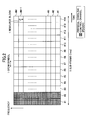
- the length of one sub-frame is 1 ms and there are fourteen (14) OFDM symbols in one sub-frame.
- the numbers along the time (lateral) axis (#1, #2, #3, ..., #14) refer to the numbers identifying the OFDM symbols
- the numbers along the frequency (vertical) axis (#1, #2, #3, ..., #M-1, #M; M: an integer greater than zero (0)) refers to the numbers identifying Resource Blocks.
- the Physical Downlink Control Channel is mapped to the first M OFDM symbols (from the left-hand edge) in one sub-frame.
- the symbol M denotes any value in a rage of 1, 2, and 3 (one of three values).
- SCH Synchronization Channel
- BCH Broadcast Channel
- M resource blocks are defined (this symbol M denotes the number of resource blocks in the frequency direction).
- the frequency band per one resource block is, for example, 180 kHz, and there are twelve (12) sub-carriers in one resource block.
- a value of M (which denotes the number of resource blocks in the frequency direction) is 25, 50, or 100 when the system bandwidth is 5 MHz, 10 MHz, or 20 MHz, respectively.
- FIG. 3 shows an example of sub-carrier mapping to the OFDM symbols upon the sub-frame having the configuration as shown in FIG. 2 .
- a symbol L denotes the number of sub-carriers that can be mapped to one OFDM symbol (L is an integer greater than zero (0)), so that the sub-carriers are numbered as sub-carrier #1, #2, ..., #L in increasing order from the subcarrier having the smallest frequency.
- a value of L (which denotes the number of sub-carriers in the frequency direction) is 300, 600, or 1,200 when the system bandwidth is 5 MHz, 10 MHz, or 20MHz, respectively.
- L is an integer greater than zero (0)
- a Downlink Reference Signal (DL RS) and the Physical Downlink Control Channel (PDCCH) are mapped to the sub-carriers of the OFDM symbol #1, and the Physical Downlink Control Channel (PDCCH) is mapped to the sub-carriers of the OFDM symbol #2.
- DL RS Downlink Reference Signal
- PDCCH Physical Downlink Control Channel
- the Downlink Reference Signal (DL RS) is transmitted by one sub-carrier out of every six (6) sub-carriers in the OFDM symbol #1.
- the Downlink Reference Signals (DL RS) are mapped to sub-carrier #6 ⁇ d-5 (d:1, 2,...), and the Physical Downlink Control Channel (PDCCH) is mapped to the sub-carriers other than the sub-carriers to which the Downlink Reference Signals (DL RS) are mapped.
- FIG. 3 shows a case where the Acknowledgement information (UL ACK/NACK) as the information item to be transmitted via the Physical Downlink Control Channel (PDCCH) is mapped to sub-carrier #3 and sub-carrier #L-3.
- the number of sub-carriers to which the Acknowledgement information (UL ACK/NACK) is mapped may be determined based on the maximum number of the user equipment terminals to be multiplexed in one sub-frame in uplink, namely, the maximum number of the user equipment terminals transmitting the uplink shared channel in one sub-frame.
- the configuration of the OFDM symbol #3 in a case where the number of OFDM symbols to be mapped to the Physical Downlink Control Channel (PDCCH) is three (3) is basically the same as that of the OFDM symbol #2 in FIG. 3 .
- the base station apparatus 200 includes a transmission/receiving antenna 202, an amplifier 204, a transmission/receiving section 206, a baseband signal processing section 208, a call processing section 210, and a channel interface 212.
- the packet data transmitted from the base station apparatus 200 to the user equipment (UE) 100 n in downlink are input from an upper node station of the base station apparatus 200 such as an access gateway 300 to the baseband signal processing section 208 through the channel interface 212.
- the baseband signal processing section 208 performs a PDCP (Packet Data Convergence Protocol) layer process such as adding sequence numbers, a concealing process using the sequence numbers, an RLC (Radio Link Control) layer process such as segmentation and concatenation of packet data and a transmission process of RLC retransmission control, MAC (Medium Access Control) retransmission control such as an HARQ (Hybrid Automatic Repeat reQuest) transmission process, a scheduling process, a transmission format selection process, a channel coding process, and an IFFT (Inverse Fast Fourier Transformation) process and transmits the resulting output to the transmission/receiving section 206.
- PDCP Packet Data Convergence Protocol
- RLC Radio Link Control
- MAC Medium Access Control
- HARQ Hybrid Automatic Repeat reQuest
- the baseband signal processing section 208 determines the transmission power allocated to, for example, the resource blocks (or sub-carriers) in each sub-frame and the Downlink Reference Signal (DL RS), the Physical Downlink Control Channel (PDCCH), user data (Downlink-Shared Channel (DL-SCH) as the transport channel (TrCH)), Synchronization Channel (SCH), Broadcast Channel (BCH), and the data signal in Persistent Scheduling in each OFDM symbol.
- DL RS Downlink Reference Signal
- PDCCH Physical Downlink Control Channel
- DL-SCH Downlink-Shared Channel
- TrCH transport channel
- SCH Synchronization Channel
- BCH Broadcast Channel
- the transmission/receiving section 206 performs a frequency conversion process from a baseband signal to a signal in a radio-frequency band, the baseband signal being output from the baseband signal processing section 208. Then, the signal in the radio-frequency band is amplified by the amplifier 204 and transmitted through the transmission/receiving antenna 202.
- a radio-frequency band signal is received by the transmission/receiving antenna 202, amplified by the amplifier 204, frequency-converted from the radio-frequency band signal to a baseband signal by the transmission/receiving section 206, and input to the baseband signal processing section 208.
- the baseband signal processing section 208 performs an FFT (Fast Fourier Transformation) process, an IDFT (Inverse Discrete Fourier Transformation) process, an error-correcting decoding process, a receiving process of the MAC retransmission control, a receiving process of the RLC layer (data) and the PDCP layer (data) on the input baseband signal and transmits the resulting output to the access gateway 300 through the channel interface 212.
- FFT Fast Fourier Transformation
- IDFT Inverse Discrete Fourier Transformation
- the call processing section 210 performs call processing operations such as establishing and releasing a communication channel and manages the status of the base station apparatus 200 and radio resources.
- the baseband signal processing section 208 includes a layer 1 processing section 2081, an MAC processing section 2082 as a selection unit, an RLC processing section 2083, and a DL transmission power determination section 2084 as a transmission power control unit.
- the layer 1 processing section 2081, the MAC processing section 2082, the RLC processing section 2083, and the DL transmission power determination section 2084, and the call processing section 210 are connected with each other.
- the layer 1 processing section 2081 performs a channel coding process of the data to be transmitted in downlink, the IFFT process, a channel decoding process of the data transmitted in uplink, the IDFT process, the FFT process and the like. From the MAC processing section 2082, the layer 1 processing section 2081 receives an ID (Identification information) of a user equipment (UE) terminal communicating using the Physical Downlink Shared Channel (PDSCH); the transport format information of the user data, namely the Downlink Scheduling Information and an ID of a user equipment (UE) terminal communicating using the Physical Uplink Shared Channel (PUSCH); and the transport format information of the user data, namely the Uplink Scheduling Grant.
- ID Identity information
- the layer 1 processing section 2081 performs transmission processes such as a channel coding process and an IFFT process and the like on the ID of the user equipment (UE) terminal communicating using the Physical Downlink Shared Channel (PDSCH) and the transport format information of the user data, namely the Downlink Scheduling Information; the ID of the user equipment (UE) terminal communicating using the Physical Uplink Shared Channel (PUSCH) and the transport format information of the user data, namely the Uplink Scheduling Grant.
- PDSCH Physical Downlink Shared Channel
- PUSCH Physical Uplink Shared Channel
- the ID of the user equipment (UE) terminal communicating using the Physical Downlink Shared Channel (PDSCH) and the transport format information of the user data, namely the Downlink Scheduling Information and the ID of the user equipment (UE) terminal communicating using the Physical Uplink Shared Channel (PUSCH) and the transport format information of the user data, namely the Uplink Scheduling Grant are mapped to the Physical Downlink Control Channel (PDCCH) which is the control channel in downlink.
- PDSCH Physical Downlink Control Channel
- the layer 1 processing section 2081 Based on the transmission power information reported from the DL transmission power determination section 2084, the layer 1 processing section 2081 sets the transmission power of sub-carriers to which the Downlink Reference Signal (DL RS), the Physical Downlink Control Channel (PDCCH), the user data, the Synchronization Channel (SCH), the Broadcast Channel (BCH), the data signal in Persistent Scheduling and the like are mapped.
- DL RS Downlink Reference Signal
- PDCCH Physical Downlink Control Channel
- SCH Synchronization Channel
- BCH Broadcast Channel
- the layer 1 processing section 2081 decodes the CQI included in the uplink baseband signal transmitted from the user equipment (UE) 100 n and reports the decoded CQI to the MAC processing section 2082 and the DL transmission power determination section 2084.
- the MAC processing section 2082 performs the MAC retransmission control of downlink user data such as the HARQ transmission process, the scheduling process, the transmission format selection process, a frequency resource allocation process and the like.
- scheduling refers to a process of selecting (sorting) the user equipment (UE) terminals to communicate using the Shared Channel in the sub-frames.
- the algorithm for the process there are the round robin, the Proportional Fairness, and the MAX C/I.
- an evaluation metric of each user equipment terminal is calculated, and a process is performed in which a user equipment (UE) terminal having a larger evaluation metric is selected as the user equipment (UE) terminal to communicate by using a Shared Channel in the sub-frames.
- the evaluation metric corresponds to a priority level indicating a priority order of allocating the radio resources.
- the user equipment (UE) terminal to which the radio resources are allocated is determined.
- the term transmission format selection refers to the determination of the information (data) of the transport format such as a modulation scheme, a coding rate, and data size related to the downlink shared channel transmitted to the user equipment (UE) 100 n selected in the scheduling process.
- the modulation scheme, the coding rate, and the data size may be determined based on, for example, the CQI reported from the user equipment (UE) 100 n in uplink.
- the term frequency resource allocation (process) refers to a process of determining resource blocks to be used for the transmission of the downlink shared channel transmitted to the user equipment (UE) 100 n selected in the scheduling process.
- the resource blocks may be determined based on, for example, the CQI reported from the user equipment (UE) 100 n in uplink.
- the CQI is reported from the layer 1 processing section 2081. Further, the MAC processing section 2082 reports the ID of the user equipment terminal communicating the Physical Downlink Shared Channel (PDSH) and the transport format information of the user data, namely the Downlink Scheduling Information, to the layer 1 processing section 2081 and the DL transmission power determination section 2084.
- the ID of the user equipment terminal and the transport format information of the user data is determined by the scheduling process, the transmission format selection process, and the frequency resource allocation process.
- the MAC processing section 2082 performs a receiving process of the MAC retransmission control of uplink user data, the scheduling process, the transmission format selection process, the frequency resource allocation process and the like.
- scheduling process refers to a process of selecting a user equipment terminal to transmit the user data using the Shared Channel in predetermined sub-frames.
- transmission format selection process refers to a process of determining the transport format data such as the modulation scheme, the coding rate, and the data size of the user data transmitted by the user equipment (UE) 100 n selected in the scheduling process.
- the modulation scheme, the coding rate, and the data size may be determined based on, for example, an SIR (Signal-to-Interference Ratio) or a path loss of a sounding reference signal transmitted in uplink from the user equipment (UE).
- the path loss may be estimated based on, for example, the received power of the sounding reference signal and information of uplink transmission power reported from the user equipment (UE) 100 n such as UE Power Headroom.
- the term frequency resource allocation process refers to a process of determining resource blocks to be used for the transmission of the user data transmitted by the user equipment (UE) 100 n selected in the scheduling process.
- the resource blocks may be determined based on, for example, the SIR of the sounding reference signal transmitted in uplink from the user equipment (UE).
- the MAC processing section 2082 reports the ID of the user equipment terminal communicating using the Physical Uplink Shared Channel (PUSCH) and the transport format information of the user data, namely the Uplink Scheduling Grant, to the layer 1 processing section 2081 and the DL transmission power determination section 2084.
- the ID of the user equipment terminal and the transport format information of the use data is determined by the scheduling process, the transmission format selection process, and the frequency resource allocation process.
- the MAC processing section 2082 may determine the resource blocks that can be allocated to the user data (Downlink-Shared Channel (DL-SCH) as the transport channel (TrCH)). And, the MAC processing section 2082 performs the scheduling process, the transmission format selection process, and the frequency resource allocation process on the resource blocks that can be allocated to the user data.
- DL-SCH Downlink-Shared Channel
- TrCH transport channel
- the MAC processing section 2082 receives a transmission power P BCH of the Broadcast Channel (BCH) in the sub-frame, a transmission power P SCH of the Synchronization Channel (SCH) in the sub-frame, a transmission power P data,TPC of the data signal in Persistent Scheduling, a transmission power P data (unit) per one sub-carrier of the user data (Downlink-Shared Channel (DL-SCH) as the transport channel (TrCH)) in the sub-frame, and the maximum transmission power P total of the base station apparatus 200 from the DL transmission power determination section 2084 as transmission power information.
- BCH Broadcast Channel
- SCH Synchronization Channel
- a transmission power P data,TPC of the data signal in Persistent Scheduling
- a transmission power P data (unit) per one sub-carrier of the user data Downlink-Shared Channel (DL-SCH) as the transport channel (TrCH)
- TrCH transport channel
- the number of resource blocks Num RB (data) that can be allocated to the user data may be calculated based on P BCH , P SCH , P data, TPC, P data (unit) , and P total .
- the RLC processing section 2083 performs segmentation and concatenation of downlink packet data, a transmission process of the RLC layer (data) such as a transmission process of the RLC retransmission control, segmentation and concatenation of uplink packet data, and a receiving process of the RLC layer (data) such as a receiving process of the RLC retransmission control. Further, the RLC processing section 2083 may perform transmission/receiving processes of downlink and uplink PDCP layer (data).
- the DL transmission power determination section 2084 determines the transmission power of the Downlink Reference Signal (DL RS), the Physical Downlink Control Channel (PDCCH), the user data, the Synchronization Channel (SCH), the Broadcast Channel (BCH), the data signal in Persistent Scheduling and the like and reports the determined transmission power of the Downlink Reference Signal (DL RS), the Physical Downlink Control Channel (PDCCH), the user data, the Synchronization Channel (SCH), the Broadcast Channel (BCH), the data signal in Persistent Scheduling and the like to the layer 1 processing section 2081 and the MAC processing section 2082 as the transmission power information.
- DL RS Downlink Reference Signal
- PDCH Physical Downlink Control Channel
- SCH Synchronization Channel
- BCH Broadcast Channel
- the values of the transmission power of the Downlink Reference Signal (DL RS), the Synchronization Channel (SCH), and the Broadcast Channel (BCH) are generally fixed values and determined by referring to a value reported through signaling from an upper layer or a value set as an internal parameter in the base station apparatus 200. Further, the transmission power of the data signal in Persistent Scheduling may be determined based on, for example, a CQI value reported from the user equipment (UE) terminal.
- UE user equipment
- the transmission power per one sub-carrier of the user data Downlink-Shared Channel (DL-SCH) as the transport channel (TrCH)
- the transmission power per one sub-carrier of the Physical Downlink Shared Channel (PDSCH) may be used, assuming that the transmission power is equally allocated to all the sub-carriers across the system bandwidth.
- the Physical Downlink Control Channel may also be called a Downlink L1/L2 Control Channel (DL L1/L2 Control Channel).
- the transmission power of the Downlink Reference Signal (DL RS) may be set in advance through an external input interface (IF).
- IF external input interface
- a transmission power per one resource element of the Downlink Reference Signal (DL RS) is defined as P DLRS and the number of the resource elements of the Downlink Reference Signal (DL RS) in the first OFDM symbol(s) in the sub-frame is defined as n DLRS .
- the term to be set through the external input interface refers to being set by a fixed value as a parameter, and a value of the parameter may be stored as an internal parameter of the base station apparatus 200, or may be remotely specified from a node in the core network 400 or the access gateway 300.
- the transmission power of the Broadcast Channel (BCH) may be set in advance through an external input interface (IF), namely, as described above, a fixed value is set as the transmission power of the Broadcast Channel (BCH).
- IF external input interface
- TPC Transmission Power Control
- PCH Physical Downlink Shared Channel
- the Transmission Power Control (TPC) of a Synchronization Channel namely, the Transmission Power Control (TPC) of a Primary-Synchronization Channel (P-SCH) and a Secondary-Synchronization Channel (S-SCH) are described.
- the transmission power of the Synchronization Channel (SCH) may be set through an external input interface (IF), namely, as described above, a fixed value is set as the transmission power of the Synchronization Channel (SCH).
- the Random Access Channel Response corresponds to message 2 in a random access procedure. It is assumed that the transmission power of the Random Access Channel Response (RACH response) is the same as that of the Physical Downlink Shared Channel (PDSCH). In other words, as the transmission power of the Random Access Channel Response (RACH response), a value of the transmission power per one sub-carrier is set assuming that the transmission power is equally allocated to all the sub-carriers across the system bandwidth. Therefore, as described above, a fixed value is set as the transmission power of the Random Access Channel Response (RACH response).
- the transmission power per one sub-carrier of the Paging Channel (PCH) and the transmission power per one sub-carrier of the Random Access Channel Response (RACH response) are the same as that of the Physical Downlink Shared Channel (PDSCH).
- the transmission power per one sub-carrier of the Paging Channel (PCH) and the transmission power per one sub-carrier of the Random Access Channel Response (RACH response) may be set through the external input interface (IF) like the Synchronization Channel (SCH) or the Broadcast Channel (BCH).
- IF external input interface
- SCH Synchronization Channel
- BCH Broadcast Channel
- TPC Transmission Power Control
- a symbol m (m: an integer) is used as an index of the OFDM symbols. More specifically, the values of m (0, 1, 2, ...) are sequentially defined to denote the OFDM symbols arranged from the header (left-hand edge of FIG. 2 ) of one sub-frame. Further, the symbol M denotes the number of OFDM symbols allocated to the Physical Downlink Control Channel (PDCCH).
- DL L1/L2 Control Channel Format Indicator which is also called Category 0 Information
- DL Scheduling Information the Downlink Scheduling Information
- UL ACK/NACK the Acknowledgement Information
- TPC bit the Transmission Power Control Command Bit
- the Downlink L1/L2 Control Channel Format Indicator is the information designating the number of OFDM symbols allocated to the Physical Downlink Control Channel (PDCCH) (i.e., a value of the symbol M as described above).
- the number of OFDM symbols allocated to the Physical Downlink Control Channel (PDCCH) depends on the number of simultaneously multiplexed users and received quality of the multiplexed users. Typically, a sufficiently large number is to be set as the number of OFDM symbols allocated to the Physical Downlink Control Channel (PDCCH). However, when the number of simultaneously multiplexed users is small, the number of OFDM symbols allocated to the Physical Downlink Control Channel (PDCCH) decreases. Therefore, if the number of simultaneously multiplexed users and the received quality of the multiplexed users differ among the sub-frames, the Physical Downlink Control Channel (PDCCH) having sufficiently large bandwidth may not be effectively used.
- the number of OFDM symbols allocated to the Physical Downlink Control Channel (PDCCH) (i.e., the value of the symbol M as described above) is reported by using the Downlink L1/L2 Control Channel Format Indicator mapped to the Physical Downlink Control Channel (PDCCH).
- the number of OFDM symbols allocated to the Physical Downlink Control Channel (PDCCH) (i.e., the value of the symbol M as described above) is adequately set with respect to each sub-frame.
- the DL transmission power determination section 2084 determines the transmission power of the Downlink L1/L2 Control Channel Format Indicator, the transmission power of the Overload Indicator, the transmission power of the Acknowledgement Information (UL ACK/NACK), and the transmission power of the Transmission Power Control Command Bit (TPC bit). Further, the DL transmission power determination section 2084 determines the transmission power of the Downlink Scheduling Information (DL Scheduling Information) and the transmission power of the Uplink Scheduling Grant, and further determines the number of OFDM symbols allocated to the Physical Downlink Control Channel (PDCCH) (i.e., the value of the symbol M as described above).
- DL Scheduling Information Downlink Scheduling Information
- the Uplink Scheduling Grant the number of OFDM symbols allocated to the Physical Downlink Control Channel (PDCCH) (i.e., the value of the symbol M as described above).
- the Overload Indicator may not be transmitted and the rest of the signals, i.e., the Downlink L1/L2 Control Channel Format Indicator, the Acknowledgement Information (UL ACK/NACK), the Transmission Power Control Command Bit (TPC bit), the Downlink Scheduling Information (DL Scheduling Information), and the Uplink Scheduling Grant may be transmitted via the Physical Downlink Control Channel (PDCCH).
- the Physical Downlink Control Channel i.e., the Overload Indicator may not be transmitted and the rest of the signals, i.e., the Downlink L1/L2 Control Channel Format Indicator, the Acknowledgement Information (UL ACK/NACK), the Transmission Power Control Command Bit (TPC bit), the Downlink Scheduling Information (DL Scheduling Information), and the Uplink Scheduling Grant may be transmitted via the Physical Downlink Control Channel (PDCCH).
- TPC bit #k CQI average ULACK l dB CQI value related to the entire downlink system bandwidth of the user equipment which is the transmission target of the UL ACK/NACK This CQI value is reported from layer 1 processing section 2081.
- Index I corresponds one-to-one to the number of UL-SCH transmitted by the user equipment.
- Index k corresponds to index of TPC bit.
- CQI average , UL k_ul dB CQI value related to the entire downlink system bandwidth and reported from the user equipment #k_ul which is the transmission target of Uplink Scheduling Grant This CQI value is reported from layer 1 processing section 2081.
- This value is set through the external input interface (IF).
- M UNIT The number of OFDM symbols used for Physical Downlink Control Channel. This value is calculated in an embodiment of the present invention P cat0 W Transmission power (absolute value) per one resource element of Downlink L1/L2 Control Channel Format Indicator This value is calculated in an embodiment of the present invention n cat0 UNIT The number of resource elements of Downlink L1/L2 Control Channel Format Indicator P OLI IF W Transmission power (absolute value) per one resource element of Overload Indicator assuming that the number M of OFDM symbols used for Physical Downlink Control Channel is 1. This value is set through the external input interface (IF). n OLI UNIT The number of resource elements per one OFDM symbol of Overload Indicator.
- n ACK UNIT The number of resource elements per one OFDM symbol per one user equipment of UL ACK/NACK L ACK UNIT The number of UL ACK/NACK transmitted to the sub-frame This number corresponds to the number of user equipment transmitting UL-SCH in the sub-frame where the UL-SCH corresponding to the UL ACK/NACK is transmitted. Namely this number corresponds to the multiplexing number of UL-SCH.
- P TPC max W Transmission power (absolute value) per one resource element of TPC bits when CQI is reference CQI (CQIaverage(min)) assuming that the number M of OFDM symbols used for Physical Downlink Control Channel is 1. This value is set through the external input interface (IF).
- P TPC min W The minimum value (absolute value) of the Transmission power per one resource element of TPC bits assuming that the number M of OFDM symbols used for Physical Downlink Control Channel is 1. This value is set through the external input interface (IF).
- n TPC UNIT The number of resource elements per one OFDM symbol per one user equipment terminal of TCP bit
- K TPC UNIT The number of TPC bits transmitted to the sub-frame. It is assumed this number corresponds to the number of TCP bit actually transmitted.
- This value is set through the external input interface (IF).
- P DL - L ⁇ 1 ⁇ L ⁇ 2 m in W The minimum value (absolute value) of the Transmission power per one resource element of Downlink Scheduling Information This value is set through the external input interface (IF).
- n DL - L ⁇ 1 ⁇ L ⁇ 2 i m Resource element The number of resource elements per one user equipment of the Downlink Scheduling Information in the mth OFDM symbol when ith MCS is used.
- P UL - L ⁇ 1 ⁇ L ⁇ 2 min W The minimum value (absolute value) of the Transmission power per one resource element of Uplink Scheduling Grant This value is set through the external input interface (IF).
- IF external input interface
- n UL - L ⁇ 1 ⁇ L ⁇ 2 i m Resource element The number of resource elements per one user equipment of the Uplink Scheduling Grant in the mth OFDM symbol when ith MCS is used.
- P L 1 L 2, RACHmessag e3 W Transmission power (absolute value) per one resource element of the Uplink Scheduling Grant when user equipment #k_dl transmits message 3 in random access procedure This value is set through the external input interface (IF).
- Control Channel Format Indicator is set through the external input interface (IF).
- the transmission power (absolute value) per one resource element of the Downlink L1/L2 Control Channel Format Indicator is defined as P cat0 . Further, the number of the resource elements of the Downlink L1/L2 Control Channel Format Indicator is defined as n cat0 .
- the transmission power (absolute value) per one resource element of the Overload Indicator is defined as P OLI , which is calculated as shown in formula 1.
- the number of the resource elements per one OFDM symbol of the Overload Indicator is defined as n OLI
- the transmission power (absolute value) of the Overload Indicator set through the external input interface (IF) is defined as P OLI (IF) .
- P OLI P OLI IF / M
- P OLI (IF) is divided by M in formula (1).
- the transmission power of the Acknowledgement Information (UL ACK/NACK) is described.
- the transmission power of the Acknowledgement Information (UL ACK/NACK) is calculated based on the CQI value (CQI average , ULACK (1) ) for the entire downlink system bandwidth, i.e. the wideband CQI value, reported from the user equipment (UE) terminal which is the transmission source of the Acknowledgement Information (UL ACK/NACK).
- the CQI value (CQI average , ULACK (1) ) for the entire downlink system bandwidth, i.e. the wideband CQI value, is included in the CQI information reported from the layer 1 processing section 2081.
- an index 1 is an index corresponding one-to-one to the number of (resource elements of) an Uplink-Shared Channel (UL-SCH).
- the corresponding relationship between the number of the (resource elements of) Acknowledgement Information (UL ACK/NACK) and the number of (resource elements of) the Uplink-Shared Channel (UL-SCH) is described in, for example, Non Patent Document 4.
- P ACK , tmp l Max P ACK max ⁇ 10 CQI average min - CQI average , ULACK l / 10 , P ACK min
- a symbol P ACK (max) denotes the transmission power (absolute value) per one resource element of the Acknowledgement Information (UL ACK/NACK) when the CQI value is CQI average (min) and a symbol P ACK (min) denotes the minimum value (absolute value) of the transmission power per one resource element of the Acknowledgement Information (UL ACK/NACK).
- p ACK (max) , CQI average (min) , and P ACK (min) is set through the external input interface (IF).
- the number of resource elements per one OFDM symbol of the Acknowledgement Information (UL ACK/NACK) is defined as n ACK and the number of (resource elements of) the Acknowledgement Information (UL ACK/NACK) actually transmitted in the sub-frame is defined as L ACK .
- the number of (resource elements of) the Acknowledgement Information (UL ACK/NACK) L ACK corresponds to the number of user equipment (UE) terminals to transmit the Uplink-Shared Channel (UL-SCH) in the sub-frame where the Uplink-Shared Channel (UL-SCH) corresponding to the Acknowledgement Information (UL ACK/NACK) is transmitted, namely the multiplexing number of the Uplink-Shared Channel (UL-SCH).
- the transmission power P ACK (1) (absolute value, unit: W) per one resource element of the Acknowledgement Information (UL ACK/NACK) is finally calculated in accordance with the following formula (3).
- P ACK 1 P ACK , tmp 1 / M
- the transmission power of the Transmission Power Control Command Bit (TPC bit) is calculated based on the CQI value for the entire downlink system bandwidth (CQI average,TPC (k) ), i.e. the wideband CQI value, reported from the user equipment (UE) terminal which is the transmission source of the Transmission Power Control Command Bit (TPC bit).
- the CQI value (CQI average,ULACK (k) ) related to the entire downlink system bandwidth, i.e. the wideband CQI value, is included in the CQI information reported from the layer 1 processing section 2081.
- an index k denotes an Index of the Transmission Power Control Command Bit (TPC bit) (or a number corresponds one-to-one to a number of an uplink sounding reference signal in a sub-frame which is N TPC (sub-frame(s)) before the sub-frame).
- P TPC , tmp k Max P TPC max ⁇ 10 CQI average min - CQI average , TPC k / 10 , P TPC min
- the symbol P TPC (max) denotes a transmission power (absolute value) per one resource element of the Transmission Power Control Command Bit (TPC bit) when the value of CQI is a predetermined value CQI average (min) and the symbol P TPC (min) denotes the minimum value (absolute value) of the transmission power per one resource element of the Transmission Power Control Command Bit (TPC bit).
- P TPC (max) , CQI average (min) , and P TPC (min) is set through the external input interface (IF).
- n TPC the number of resource elements per one OFDM symbol of the Transmission Power Control Command Bit (TPC bit)
- K TPC the number of the Transmission Power Control Command Bit (TPC bit) actually transmitted in the sub-frame.
- the transmission power P PCT (k) (absolute value, unit: W) per one resource element of the Transmission Power Control Command Bit (TPC bit) is finally calculated in accordance with the following formula (5).
- P TPC k P TPC , tmp k / M
- the DL transmission power determination section 2084 determines the transmission power of the Downlink Scheduling Information (DL Scheduling Information) and the transmission power of the Uplink Scheduling Grant.
- the number M of OFDM symbols allocated to the Physical Downlink Control Channel is calculated as described below based on the CQI value related to the entire system bandwidth, i.e. the wideband CQI value, of "the user equipment (UE) terminal selected as the user equipment (UE) terminal communicating using a shared channel in the sub-frame" in the scheduling of the downlink user data (Downlink-Shared Channel (DL-SCH) as the transport channel (TrCH)) and the uplink user data (Uplink-Shared Channel (UL-SCH) as the transport channel (TrCH)) in the MAC processing section 2082.
- DL-SCH Downlink-Shared Channel
- UL-SCH Uplink-Shared Channel
- the number of blocks for the control channel related to the Downlink Scheduling Information of the user equipment terminal #k_dl is defined as N k_dl
- the number of blocks for the control channel related to the Uplink Scheduling Grant of the user equipment terminal #k_ul is defined as N k_ul .
- the block for the control channel refers to a group of resource elements and is a unit of resources to be allocated to the Downlink Scheduling Information and the Uplink Scheduling Grant.
- the block for the control channel may also be called a Control Channel Element (CCE).
- a Mini CCE obtained by further dividing the Control Channel Element (CCE) may be defined as the block for the control channel.
- the Mini CCE may be composed of four resource elements.
- Adaptive Modulation and Coding may be applied to the Downlink Scheduling Information and the Uplink Scheduling Grant.
- AMC Adaptive Modulation and Coding
- MCSs Modulation and Coding Schemes
- MCS No. 0 two (2) Modulation and Coding Schemes
- MCS No. 1 two (2) blocks for the control channel are allocated to the second MCS
- MCS No. 1 The number of the Modulation and Coding Schemes (MCSs) is not limited to two (2), and three (3) or more Modulation and Coding Schemes (MCSs) may be applied.
- one DL L1/L2 symbol is spread by Walsh code having spreading factor 4, so that one code resource in one DL L1/L2 symbol is allocated to one block for the control channel.
- the resources are allocated in each G L1L2 ; therefore, the resources corresponding to twenty-eight (28) resource elements are allocated to one block for the control channel.
- the numbers of the blocks for the control channel are allocated in ascending order in frequency direction first and then allocated in ascending order in code direction.
- the MCS No. 0 i.e., the first MCS
- the MCS No. 1 i.e., the second MCS
- the MCS is separately set with respect to each user equipment (UE) terminal.
- the MCS No. is set by RRC (Radio Resource Control) message.
- RRC Radio Resource Control
- the Downlink Scheduling Information and the Uplink Scheduling Grant are multiplexed with the Physical Downlink Control Channel (PDCCH) using a combined multiplexing scheme of a code division multiplexing scheme and a frequency division multiplexing scheme.
- the transmission power control method described below may also be applied when the Downlink Scheduling Information and the Uplink Scheduling Grant are multiplexed with the Physical Downlink Control Channel (PDCCH) using the frequency division multiplexing scheme.
- the transmission power control method described below may also be applied even when the Downlink Scheduling Information and the Uplink Scheduling Grant are multiplexed with the Physical Downlink Control Channel (PDCCH) using the code division multiplexing scheme.
- control method of the present invention may also be applied when the block for the control channel is defined as a combination of resources not described above.
- the transmission power of the Downlink Scheduling Information of the user equipment (UE) terminal #k_dl is defined as P DL-L1L2,tmp (k_dl) .
- the number of the resource elements per one user equipment (UE) terminal for the Downlink Scheduling Information is defined as n DL-L1L2,tmp (i) .
- the transmission power of the Uplink Scheduling Grant of the user equipment (UE) terminal #k_ul is defined as P UL-L1L2,tmp (k_ul) .
- the number of the resource elements per one user equipment (UE) terminal for the Uplink Scheduling Grant is defined as n UL-L1L2,tmp (i) .
- N all a value of N all is calculated using formula (6).
- formula (6) a total of a sum of the numbers of the resource elements used for each Downlink Scheduling Information to be transmitted in the sub-frame and a sum of the numbers of the resource elements used for each Uplink Scheduling Grant to be transmitted in the sub-frame is calculated.
- a transmission power of each Downlink Scheduling Information namely a transmission power P DL-L1L2 , tmp (k_dl) related to the Downlink Scheduling Information of the user equipment (UE) terminal #k_dl is calculated.
- the P L1L2,RACHres is a fixed value set through the external input interface (IF).
- the formula P DL-L1L2,tmp (k_dl) P L1L2,PICH is satisfied.
- the P L1L2,PICH is a fixed value set through the external input interface (IF).
- the Dynamic Broadcast Channel may also be transmitted.
- the P L1L2,D-BCH is a fixed value set through the external input interface (IF).
- the transmission power P DL-L1L2,tmp (k_dl) related to the Downlink Scheduling Information of the user equipment (UE) terminal #k_dl is calculated based on the CQI value CQI average,DL (k_dl) related to the downlink system bandwidth (the wideband CQI value), the CQI value CQI average,DL (k_dl) being reported from the user equipment (UE) terminal #k_dl which is the transmission source of the Downlink Scheduling Information.
- the CQI value CQI average,DL (k_d1) related to the downlink system bandwidth (the wideband CQI value) is included in the CQI information reported from the layer 1 processing section 2081.
- P DL - L ⁇ 1 ⁇ L ⁇ 2 , tmp k_dl Max P DL - L ⁇ 1 ⁇ L ⁇ 2 max MCS DL - L ⁇ 1 ⁇ L ⁇ 2 k_dl ⁇ 10
- P DL - L ⁇ 1 ⁇ L ⁇ 2 max MCS DL - L ⁇ 1 ⁇ L ⁇ 2 k_dl denotes the transmission power (absolute value) per one resource element of the Downlink Scheduling Information when the CQI is the predetermined value CQI average (min)
- P DL-L1L2 (min) denotes the minimum value (absolute value) of the transmission power per one resource element of the Downlink Scheduling Information.
- ⁇ k_dl (DL) denotes a fixed offset value.
- each of the formula (A), CQI average (min) , P DL-L1L2 (min) , and ⁇ k_dl (DL) is set through the external input interface (IF).
- the superscript suffix MCS DL-L1L2 (k_dl) in the formula (A) denotes an index indicating the MCS No. of the DL scheduling Information to be transmitted to the user equipment (UE) terminal #k_dl. Namely, by defining the formula (A) with respect to each MCS, adequate transmission power control may become possible with respect to each MCS.
- the transmission power is controlled so as not to be equal to or less than the minimum value P DL-L1L2 (min) .
- the transmission power may be controlled so as not to be equal to or less than the minimum value and so as not to be equal to or greater than the maximum value at the same time as well.
- the transmission power of each Uplink Scheduling Grant namely, the transmission power P DL-L1L2,tmp (k_ul) related to the Uplink Scheduling Grant of the user equipment (UE) terminal #k_ul is calculated.
- P DL-L1L2,tmp (k_ul) P L1L2,RACHmessage3 is satisfied.
- the P L1L2,RACHmessage3 is a fixed value set through the external input interface (IF).
- the transmission power P UL-L1L2,tmp (k_ul) related to the Uplink Scheduling Grant of the user equipment (UE) terminal #k_ul is calculated based on the CQI value CQI average,UL (k_ul) related to the downlink system bandwidth (the wideband CQI), the CQI value CQI average,UL (k_ul) being reported from the user equipment (UE) terminal #k_ul which is the transmission destination of the Uplink Scheduling Grant.
- the CQI value CQI average,UL (k_ul) related to the downlink system bandwidth (the wideband CQI) is included in the CQI information reported from the layer 1 processing section 2081.
- P UL - L ⁇ 1 ⁇ L ⁇ 2 , tmp k_ul Max P UL - L ⁇ 1 ⁇ L ⁇ 2 max MCS DL - L ⁇ 1 ⁇ L ⁇ 2 k_ul ⁇ 10
- P UL - L ⁇ 1 ⁇ L ⁇ 2 max MCS DL - L ⁇ 1 ⁇ L ⁇ 2 k_ul denotes the transmission power (absolute value) per one resource element of the Uplink Scheduling Grant when the CQI is the predetermined value CQI average (min)
- P UL-L1L2 (min) denotes the minimum value (absolute value) of the transmission power per one resource element of the Uplink Scheduling Grant.
- ⁇ k_ul (UL) denotes a fixed offset value.
- each of the formula (B), CQI average (min) , P UL-L1L2 (min) , and ⁇ k_ul (UL) is set through the external input interface (IF).
- the superscript suffix MCS DL-L1L2 (k_ul) in the formula (B) denotes an index indicating the MCS No. of the UL scheduling Grant to be transmitted to the user equipment (UE) terminal #k_ul. Namely, by defining the formula (B) with respect to each MCS, adequate transmission power control may become possible with respect to each MCS.
- the transmission power is controlled so as not to be equal to or less than the minimum value P UL-L1L2 (min) .
- the transmission power may be controlled so as not to be equal to or less than the minimum value and so as not to be equal to or greater than the maximum value at the same time as well.
- an extra transmission power resource other than the transmission power resource to be used for other data of the Physical Downlink Control Channel (PDCCH) is allocated.
- the transmission power P DL/UL-L1L2 (1) that can be allocated to the Downlink Scheduling Information and the Uplink Scheduling Grant is calculated using formula (10).
- the transmission power P DL/UL-L1L2 (2) that can be allocated to the Downlink Scheduling Information and the Uplink Scheduling Grant is calculated using formula (11).
- the number of OFDM symbols allocated to the Physical Downlink Control Channel (PDCCH) is determined.
- M is 3.
- N th1 (j) and N th2 (j) are fixed values set through the external input interface (IF).
- IF external input interface
- the above descriptions may be summarized as follows.
- the number and the transmission power of the resource elements to be used for each Downlink Scheduling Information transmitted in the sub-frame and the number and the total transmission power of the resource elements to be used for each Uplink Scheduling Grant transmitted in the sub-frame are calculated, and based on the total number and the transmission power of the resource elements, the number M of OFDM symbols allocated to the Physical Downlink Control Channel (PDCCH) is determined.
- PDCCH Physical Downlink Control Channel
- the number M of OFDM symbols allocated to the Physical Downlink Control Channel is determined based on the numbers and the transmission power of the resource elements for each Downlink Scheduling Information and each Uplink Scheduling Grant transmitted in the sub-frame.
- the number M of OFDM symbols allocated to the Physical Downlink Control Channel is determined based on the numbers and the transmission power of the blocks for the control channel used for each Downlink Scheduling Information and each Uplink Scheduling Grant transmitted in the sub-frame.
- the base station apparatus 200 may determine the number M of OFDM symbols allocated to the Physical Downlink Control Channel (PDCCH) based on the numbers and the transmission power of the blocks for the control channel used for each Downlink Scheduling Information and each Uplink Scheduling Grant transmitted in the sub-frame.
- PDCCH Physical Downlink Control Channel
- the number M of OFDM symbols allocated to the Physical Downlink Control Channel is determined based on the numbers and the transmission power of the resource elements for each Downlink Scheduling Information and each Uplink Scheduling Grant transmitted in the sub-frame.
- the number M of OFDM symbols allocated to the Physical Downlink Control Channel may be determined based on only the numbers of the resource elements for each Downlink Scheduling Information and each Uplink Scheduling Grant transmitted in the sub-frame.
- the number M of OFDM symbols allocated to the Physical Downlink Control Channel (PDCCH) may be determined based on only the transmission power of the resource elements for each Downlink Scheduling Information and each Uplink Scheduling Grant transmitted in the sub-frame.
- the most appropriate number M of OFDM symbols may be determined based on the flowchart shown in FIG. 8 .
- the Control Channel Element (CCE) is a resource for the control channel and includes plural resource elements.
- the transmission power of the PCFICH, the PHICH, and the PDCCH and the number of the Control Channel Elements may be calculated based on the method described above. Further, for example, the transmission power of the PCFICH and the number of the CCEs may be defined through the external input interface (IF). Further, for example, the transmission power of the PHICH may be calculated based on the Wideband CQI reported from the user equipment (UE). Further, for example, the transmission power of the Downlink Scheduling Information and the Uplink Scheduling Grant to be mapped to the PDCCH and the number of the CCEs may be calculated using formula (7) and formula (8), respectively.
- step S804 it is determined whether there is a shortage of the transmission power resource or the CCE resource.
- the process goes to step S806.
- step S808 it is determined whether there is a shortage of the transmission power resource or the CCE resource.
- the process goes to step S810.
- step S810 the number M of OFDM symbols is set to 3 as the most adequate value.
- step S808 when determining that there is no shortage of the transmission power resource or the CCE resource (NO in step S808), the process goes to step S812. In step S812, the number M of OFDM symbols is set to 2 as the most adequate value.
- step S804 when determining that there is no shortage of the transmission power resource or the CCE resource (NO in step S804), the process goes to step S814.
- step S814 the number M of OFDM symbols is set to 1 as the most adequate value.
- the transmission power P DL-L1L2,m (k_dl) (absolute value, unit: W) per one resource element in OFDM symbol m of the user equipment (UE) terminal #k_dl and the transmission power P UL-L1L2,m (k_ul) (absolute value, unit: W) per one resource element in OFDM symbol m of the user equipment (UE) terminal #k_ul are calculated as follows.
- P DL-L1L2,m (k_dl) and P UL-L1L2,m (k_ul) are calculated as follows.
- P DL - L ⁇ 1 ⁇ L ⁇ 2 , 0 k_dl P DL - L ⁇ 1 ⁇ L ⁇ 2 , tmp k_dl
- P UL - L ⁇ 1 ⁇ L ⁇ 2 , 0 k_ul P UL - L ⁇ 1 ⁇ L ⁇ 2 , tmp k_ul
- P DL-L1L2,m (k_dl) and P UL-L1L2,m (k_ul) are calculated as follows.
- n DL - L ⁇ 1 ⁇ L ⁇ 2 MCS DL - L ⁇ 1 ⁇ L ⁇ 2 k_dl m denotes the number of resource elements for the Downlink Scheduling Information in the m th OFDM symbol when the MCS of the Downlink Scheduling Information of the user equipment (UE) terminal #k_dl is MCS DL-L1/L2,m (k_dl) .
- n UL - L ⁇ 1 ⁇ L ⁇ 2 MCS DL - L ⁇ 1 ⁇ L ⁇ 2 k_ul m denotes the number of resource elements for the Uplink Scheduling Grant in the m th OFDM symbol when the MCS of the Uplink Scheduling Grant of the user equipment (UE) terminal #k_ul is MCS DL-L1/L2,m (k_ul) .
- the formulas (12) and (13) indicate that the transmission power for the Downlink Scheduling Information and the Uplink Scheduling Grant in each OFDM symbol are determined in accordance with the number of the resource elements for the Downlink Scheduling Information and the Uplink Scheduling Grant, respectively, in the corresponding OFDM symbol.
- the symbol m denotes the index of the OFDM symbol.
- the transmission power per one resource element for the Downlink Scheduling Information and the Uplink Scheduling Grant related to the user equipment (UE) terminal #k_dl or #k_ul becomes constant.
- the transmission power P DL-L1L2,m (k_dl) and P UL-L1L2,m (k_ul ) of the Downlink Scheduling Information and the Uplink Scheduling Grant may be decreased so that the total transmission power of the base station apparatus 200 does not exceed the rated power of the base station apparatus 200.
- the base station apparatus 200 may not decrease the transmission power of all of signals, i.e. DL RS, Downlink L1/L2 Control Channel Format Indicator, Overload Indicator, UL ACK/NACK, or TCP bit.
- not only the transmission power of the Downlink Scheduling Information and the Uplink Scheduling Grant but also the transmission power of the information mapped to any Physical Downlink Control Channel may be decreased. In this case, however, the transmission power of the DL RS is not decreased. Further, alternatively, the transmission power of not only the Downlink Scheduling Information and the Uplink Scheduling Grant but also the DL RS and the data to be mapped to any Physical Downlink Control Channel may be decreased.
- the transmission power of the Downlink Scheduling Information and the Uplink Scheduling Grant is decreased, the transmission power of the Downlink Scheduling Information for the RACH response, the transmission power of the Downlink Scheduling Information for the Paging Channel (PCH), and the transmission power of the Uplink Scheduling Grant for the Message 3 in the random access procedure may not be decreased.
- the communications quality of the Downlink Scheduling Information for the RACH response, the Downlink Scheduling Information for the Paging Channel (PCH), and the Uplink Scheduling Grant for the Message 3 in the random access procedure may be maintained.
- the transmission power P DL/UL - L1L2 (3) is calculated that can be allocated to the Downlink Scheduling Information and the Uplink Scheduling Grant when assuming that the number M of OFDM symbols allocated to the Physical Downlink Control Channel (PDCCH) is 3.
- the user equipment (UE) terminal does not transmit the Uplink-Shared Channel (UL-SCH). Then, later, among the rest of the user equipment (UE) terminals, the resource allocation of the Downlink-Shared Channel (DL-SCH) and the Uplink-Shared Channel (UL-SCH) is performed.
- the resource allocation herein refers to mainly the allocation of frequency resources, i.e., the allocation of resource blocks.
- the P all is calculated using the formula (9).
- the scheduling coefficient refers to a coefficient indicating the priority level related to each user equipment (UE) terminal calculated in the scheduling process by the MAC processing section 2082 in the sub-frame.
- the scheduling coefficient refers to an evaluation metric.
- the scheduling coefficient may be calculated based on at least one of the priority level of the data to be transmitted, radio quality information reported from user equipment (UE) terminal, the number of retransmissions, information whether control information is included, frequency of allocation, average transfer rate to the user equipment (UE) terminal, a target value of the data rate to the user equipment (UE) terminal, the priority level for preferentially transmitting to the user equipment (UE) terminal when the user equipment terminal capable of DRX mode is in a reception timing mode in DRX, I.e. on-duration, and the like.
- the DL transmission power determination section 2084 may increase the priority level of downlink and uplink retransmission data in a process of determining that the communications using the shared channel are not carried out in the sub-frame with respect to the user equipment terminal selected as the user equipment terminal to communicate using the shared channel in the sub-frame. Namely, the transmission power may be preferentially allocated to the Downlink Scheduling Information for the retransmission data and the Uplink Scheduling Grant for the retransmission data.
- the DL transmission power determination section 2084 may increase the priority level of the message 2 (RA response) in the downlink random access procedure or the Paging Channel (PCH) in a process of determining that the communication using the shared channel is not performed in the sub-frame with respect to the user equipment terminal selected as the user equipment terminal to communicate using the shared channel in the sub-frame as described above. Namely, the transmission power may be preferentially allocated to the Downlink Scheduling Information for the message 2 in the downlink random access procedure or the Paging Channel (PCH). Further, in addition to the priority level of the message 2 in the downlink random access procedure or the Paging Channel (PCH) that are common channels, the priority level for the Broadcast Channel (BCH) may be increased.
- RA response the downlink random access procedure or the Paging Channel (PCH) in a process of determining that the communication using the shared channel is not performed in the sub-frame with respect to the user equipment terminal selected as the user equipment terminal to communicate using the shared channel in the sub-frame as described above. Namely, the transmission power may
- the process may be performed where the communications using the shared channel are not carried out in the sub-frame with respect to the user equipment terminal selected as the user equipment terminal to communicate using the shared channel in the sub-frame.
- the resources of the Downlink-Shared Channel (DL-SCH) and the Uplink-Shared Channel (UL-SCH) for the user equipment (UE) terminal that is determined not to communicate using the shared channel in the subframe may not be used. However, processing delay may be reduced.
- P DL-L1L2,m (k_dl) and P UL-L1L2,m (k_ul) are calculated as described below.
- m denotes the index of OFDM symbols.
- the transmission power per one resource element for the Downlink Scheduling Information and the Uplink Scheduling Grant related to the user equipment (UE) terminal #k_dl or #k_ul becomes constant.
- the Downlink L1/L2 Control Channel Format Indicator is transmitted via the Physical Downlink Control Channel (PDCCH).
- the value of M is not controlled with respect to each sub-frame but controlled with respect to each longer period (cycle) such as 10 ms or 100 ms.
- the process from (Start of determination formula) to (End of determination formula) may also be applied.
- the value of transmission power and the number of resource elements not an instantaneous value (i.e., a value of each sub-frame) but averaged values of the longer period such as 10 ms or 100 ms may be used. Otherwise, as the value of transmission power and the number of resource elements, the maximum values in the longer period may be used.
- the maximum values as the value of M, a value may be set that does not lead to any shortage of the number of resource elements and the transmission power of the Downlink Scheduling Information and the Uplink Scheduling Grant in all sub-frames; therefore it may become possible to achieve more stable communications using the control channel.
- an adequate number of OFDM symbols in each subframe in a longer period may be calculated; and the average value or the maximum value of the adequate number of OFDM symbols in the above longer period may be calculated and used as the value of M.
- the adequate number of OFDM symbols refers to the minimum value of M among the values of M which do not lead to any shortage of the number of resource elements and the transmission power in the sub-frame.
- the number M of OFDM symbols allocated to the Physical Downlink Control Channel (PDCCH) may also be determined based on a longer period. For example, based on 10 ms or 100 ms as the longer period, the average value of N all and the average value of P all may be calculated to determine the value of M. Otherwise, the value of M may be determined based on the maximum value of N all and the maximum value of P all in a 10 ms period or 100 ms period. In this case, the Downlink L1/L2 Control Channel Format Indicator is transmitted in every sub-frame.
- the value of M is fixed during the control period such as 10 ms or 100 ms as described above. As described above, by controlling the value of M in the longer period, it is no longer necessary to calculate the value of M in every sub-frame and it may become possible to decrease the complexity of base station apparatuses.
- FIG. 9 schematically shows a concept of this control.
- a value of Num corresponds to the number (value) of M. Further, the value of Num may be changed at periodic control timings (in FIG. 9 , at border lines between sub-frame 2 and sub-frame 3 and between sub-frame 12 and sub-frame 13).
- the value of M in the control period i i.e., value of Num i
- PDCCH Physical Downlink Control Channel
- the value of M may be decreased by 1 as the control of the value of M.
- the Downlink L1/L2 Control Channel Format Indicator is transmitted in every sub-frame.
- the value of M is fixed during the control period such as 10 ms or 100 ms as described above. As describe above, by controlling the value of M in a longer period (cycle), it is no longer necessary to calculate the value of M in every sub-frame and it may become possible to decrease the complexity of base station apparatuses.
- the above-mentioned processes may be performed that decreases the transmission power and that determines that the communications using the shared channel in the sub-frame are not carried out for the user equipment terminal selected as the user equipment terminal to communicate using the shared channel in the sub-frame.
- the value of M may be immediately changed regardless of the longer control period such as 10 ms or 100 ms as described above. Namely, in an event that the total transmission power of the base station apparatus 200 exceeds the maximum transmission power (rated power) of the base station apparatus 200, the value of M may be increased in the next sub-frame or in the sub-frame as early as possible as the control of the value of M. In the above process, the number of control channel resource elements may be substituted for the number of resource elements.
- FIG. 10 shows a concept of this control.
- the value of Num corresponds to the number (value) of M.
- the value of Num may be changed at periodic control timings (in FIG. 10 , at border lines between sub-frame 2 and sub-frame 3 and between sub-frame 12 and sub-frame 13).
- sub-frame 4 there is a shortage of the transmission power resource for the Downlink Scheduling Information and the Uplink Scheduling Grant or there is a shortage in the number of the resource elements used for the Downlink Scheduling Information and the Uplink Scheduling Grant.
- the value of M is changed at the border line between sub-frame 6 and sub-frame 7. In this case, for example, the number of OFDM symbols is increased by 1.
- the base station apparatus 200 may perform a process of temporarily changing the value of Num (i.e., value of M) based on whether a common channel such as the Dynamic BCH, the Paging Channel (PCH), or the DL scheduling Information is transmitted in the sub-frame. Namely, the value of M may be changed at a changing timing other than the periodic changing timing described above.
- FIG. 11 shows a concept of this control.
- the value of Num corresponds to the number (value) of M.
- the value of Num may be changed at periodic control timings (in FIG. 11 , at border lines between sub-frame 2 and sub-frame 3 and between sub-frame 12 and sub-frame 13).
- a common channel is transmitted, the value of Num is temporarily changed from Num i to Num i +Y.
- the Downlink Scheduling Information for the common channel uses more resources so that a mobile station at cell edge can correctly receive data.
- the resources correspond to the transmission power and the number of resource elements. Namely, there is a high possibility of resource shortage in the sub-frame where the common channel is transmitted.
- the value of Y may be determined based on a type of common channel to be transmitted in the sub-frame, resource usage, and the number of common channels.
- a similar process may be performed based on not only whether a common channel is to be transmitted but also whether a predetermined channel other than the common channel is to be transmitted.
- the value of M may be determined based on the number of the symbols of the Physical Downlink Control Channel (PDCCH), i.e., the number of resource elements or the number of times when there is a shortage of control channel resource elements in the longer period (cycle) such as 10 ms or 100 ms as described above.
- PDCCH Physical Downlink Control Channel
- the value of M may be decreased by 1 as the control of the value of M.
- the Downlink L1/L2 Control Channel Format Indicator is transmitted in every sub-frame.
- the value of M is fixed during the control period such as 10 ms or 100 ms as described above. As describe above, by controlling the value of M in a longer period (cycle), it is no longer necessary to calculate the value of M in every sub-frame and it may become possible to decrease the complexity of base station apparatuses.
- the number M of OFDM symbols allocated to the Physical Downlink Control Channel may be determined based on the number of mobile stations in the cell 50, more specifically, the number of mobile stations in RRC connected condition, the number of mobile stations that are in the RRC connected state and that are not in DRX state, or the number of mobile stations having data to be transmitted to a downlink transmission buffer.
- the value of M is calculated in every sub-frame so that the calculated value of M is used in the same sub-frame where the value of M is calculated.
- the calculated value of M may be used in the sub-frame which is several sub-frames after the sub-frame where the value of M is calculated.
- the value of M calculated in sub-frame 4 is used in sub-frame 6. In this case, time that can be used to calculate the value of M may be extended; therefore, it may become possible to decrease the complexity of base station apparatuses.
- an example of a system is described to which an Evolved UTRA and UTRAN (a.k.a. Long Term Evolution or Super 3G) may be applied.
- a base station apparatus and a communication control method according to an embodiment of the present invention may also be applied to any other system employing the OFDM (Orthogonal Frequency Division Multiplexing) scheme in downlink communication.
- OFDM Orthogonal Frequency Division Multiplexing
- the present invention is described by referring to specific embodiments. However, the embodiments are for illustrative purpose only and a person skilled in the art may understand that the above embodiment is described for illustrative purpose only and may think of examples of various modifications, transformations, alterations, changes and the like.
- the apparatus according to an embodiment of the present invention is described with reference to the functional block diagrams. However, such an apparatus may be provided by hardware, software, or a combination thereof.
- the present invention is not limited to the embodiment described above, and various modifications, transformations, alteration, exchanges, and the like may be made without departing from the scope and spirit of the present invention.
Landscapes
- Engineering & Computer Science (AREA)
- Signal Processing (AREA)
- Computer Networks & Wireless Communication (AREA)
- Mobile Radio Communication Systems (AREA)
Applications Claiming Priority (3)
| Application Number | Priority Date | Filing Date | Title |
|---|---|---|---|
| JP2007050835 | 2007-02-28 | ||
| JP2007161939 | 2007-06-19 | ||
| PCT/JP2008/052978 WO2008105316A1 (fr) | 2007-02-28 | 2008-02-21 | Dispositif de station de base et procédé de commande de communication |
Publications (1)
| Publication Number | Publication Date |
|---|---|
| EP2129139A1 true EP2129139A1 (fr) | 2009-12-02 |
Family
ID=39721151
Family Applications (1)
| Application Number | Title | Priority Date | Filing Date |
|---|---|---|---|
| EP08711761A Withdrawn EP2129139A1 (fr) | 2007-02-28 | 2008-02-21 | Dispositif de station de base et procédé de commande de communication |
Country Status (8)
| Country | Link |
|---|---|
| US (1) | US8274940B2 (fr) |
| EP (1) | EP2129139A1 (fr) |
| JP (1) | JP5119235B2 (fr) |
| KR (1) | KR20090122203A (fr) |
| CN (2) | CN102685870A (fr) |
| BR (1) | BRPI0807689A2 (fr) |
| RU (1) | RU2009134088A (fr) |
| WO (1) | WO2008105316A1 (fr) |
Cited By (13)
| Publication number | Priority date | Publication date | Assignee | Title |
|---|---|---|---|---|
| WO2011003180A1 (fr) * | 2009-07-06 | 2011-01-13 | Nortel Networks Limited | Attribution de ressources fondée sur la priorité et la puissance de signalisation |
| EP2296408A1 (fr) * | 2009-09-14 | 2011-03-16 | Alcatel Lucent | Procédé de planification de transmissions entre une station de base et des terminaux utilisateur, station de base et réseau de communication correspondant |
| EP2259467A3 (fr) * | 2009-06-05 | 2011-05-04 | Fujitsu Limited | Dispositif de terminal et dispositif de station de base |
| EP2439998A1 (fr) * | 2009-06-02 | 2012-04-11 | Nec Corporation | Station de base, système de communication, procédé de commande de communication et programme |
| CN102438303A (zh) * | 2011-12-28 | 2012-05-02 | 华为技术有限公司 | 一种发射分集中发射权值确定方法及用户设备 |
| WO2012139653A1 (fr) * | 2011-04-15 | 2012-10-18 | Telecom Italia S.P.A. | Procédé permettant une planification de paquets de données dans un réseau de télécommunication |
| US8351385B2 (en) | 2007-09-21 | 2013-01-08 | Panasonic Corporation | Radio communication base station device, radio communication terminal device, and response signal allocation method |
| US8457056B2 (en) | 2009-02-09 | 2013-06-04 | Qualcomm Incorporated | Non-scheduled grants in multi-carrier enhanced uplink |
| US8509133B2 (en) | 2008-07-07 | 2013-08-13 | Apple Inc. | Wireless scheduling systems and methods |
| WO2013123999A1 (fr) * | 2012-02-24 | 2013-08-29 | Nokia Siemens Networks Oy | Contrôle de puissance |
| CN105007148A (zh) * | 2010-04-01 | 2015-10-28 | Lg电子株式会社 | 无线接入系统中报告/接收功率上升空间值的方法和装置 |
| EP2355603A4 (fr) * | 2008-11-07 | 2016-06-08 | Ntt Docomo Inc | Station de base sans fil |
| WO2018211337A1 (fr) * | 2017-05-18 | 2018-11-22 | Telefonaktiebolaget Lm Ericsson (Publ) | Procédé et appareil d'évaluation et de classement de canaux à l'aide de facteurs de contrainte imposés par la protection de titulaire et de ppa |
Families Citing this family (55)
| Publication number | Priority date | Publication date | Assignee | Title |
|---|---|---|---|---|
| KR101603338B1 (ko) | 2008-08-11 | 2016-03-15 | 엘지전자 주식회사 | 무선 통신 시스템에서 정보 전송 방법 및 장치 |
| KR20100019947A (ko) | 2008-08-11 | 2010-02-19 | 엘지전자 주식회사 | 무선 통신 시스템에서 정보 전송 방법 |
| KR101571566B1 (ko) | 2008-08-11 | 2015-11-25 | 엘지전자 주식회사 | 무선 통신 시스템에서 제어신호 전송 방법 |
| MX2011002408A (es) * | 2008-09-04 | 2011-04-12 | Sharp Kk | Sistema de comunicacion movil, aparato de estacion de base, aparato de estacion movil y metodo de comunicacion. |
| WO2010035497A1 (fr) * | 2008-09-29 | 2010-04-01 | パナソニック株式会社 | Procédé d’allocation de numéro d’élément de canal de commande évolué et edispositif de station de base |
| WO2010056078A2 (fr) | 2008-11-14 | 2010-05-20 | 엘지전자주식회사 | Procédé et appareil permettant la transmission d'informations dans un système de communication sans fil |
| WO2010056068A2 (fr) | 2008-11-14 | 2010-05-20 | 엘지전자주식회사 | Procédé et appareil pour la transmission de signaux dans un système de communication sans fil |
| KR20100091876A (ko) | 2009-02-11 | 2010-08-19 | 엘지전자 주식회사 | 다중안테나 전송을 위한 단말 동작 |
| AR075865A1 (es) * | 2009-03-17 | 2011-05-04 | Interdigital Patent Holdings | Metodo y aparato para control de potencia de transmision de senal de referencia de sonido (srs) |
| US8811314B2 (en) * | 2009-03-18 | 2014-08-19 | Lg Electronics Inc. | Method and apparatus for transmitting reference signal in wireless communication system |
| CN201780605U (zh) * | 2009-04-22 | 2011-03-30 | 万信电子科技有限公司 | 服装试穿系统 |
| CN101873698B (zh) * | 2009-04-23 | 2012-12-26 | 中国移动通信集团公司 | 信号传送方法及其相关设备 |
| US8693352B2 (en) * | 2009-07-02 | 2014-04-08 | Telefonaktiebolaget L M Ericsson (Publ) | Method and apparatus for ARQ control in wireless communications |
| US9059749B2 (en) | 2009-10-02 | 2015-06-16 | Sharp Kabushiki Kaisha | Antenna port mode and transmission mode transitions |
| US8768397B2 (en) | 2009-10-02 | 2014-07-01 | Sharp Kabushiki Kaisha | Transmission power control on a wireless communication device for a plurality of regulated bands or component carriers |
| US8457079B2 (en) * | 2009-10-05 | 2013-06-04 | Motorola Mobility Llc | Method and apparatus for mitigating downlink control channel interference |
| CN102065543B (zh) | 2009-11-16 | 2014-01-01 | 中兴通讯股份有限公司 | 控制信道单元的分配方法及装置 |
| US8688163B2 (en) * | 2009-12-30 | 2014-04-01 | Qualcomm Incorporated | Interaction between accumulative power control and minimum/maximum transmit power in LTE systems |
| KR101895947B1 (ko) | 2010-01-18 | 2018-09-07 | 엘지전자 주식회사 | 무선 통신 시스템에서 채널 품질 정보를 제공하는 방법 및 장치 |
| JP5278350B2 (ja) * | 2010-02-25 | 2013-09-04 | 富士通株式会社 | 基地局装置、識別子割当方法及び識別子割当プログラム |
| US8670496B2 (en) * | 2010-04-14 | 2014-03-11 | Samsung Electronics Co., Ltd. | Method and system for mapping uplink control information |
| JP4812887B1 (ja) * | 2010-04-30 | 2011-11-09 | 株式会社エヌ・ティ・ティ・ドコモ | 移動通信方法及び移動局 |
| US8879513B2 (en) | 2010-05-12 | 2014-11-04 | Samsung Electronics Co., Ltd. | Uplink transmission apparatus and method for mobile communication system supporting uplink MIMO |
| WO2012011241A1 (fr) * | 2010-07-21 | 2012-01-26 | パナソニック株式会社 | Station de base, terminal, procédé de détermination d'espace de recherche et procédé de décodage |
| KR20120010099A (ko) * | 2010-07-22 | 2012-02-02 | 엘지전자 주식회사 | 상향링크 신호를 전송하는 방법 및 이를 위한 장치 |
| JP4852166B1 (ja) * | 2010-08-04 | 2012-01-11 | シャープ株式会社 | 移動局装置、通信システム、通信方法および集積回路 |
| US8767596B2 (en) | 2010-08-19 | 2014-07-01 | Motorola Mobility Llc | Method and apparatus for using contention-based resource zones for transmitting data in a wireless network |
| US8711789B2 (en) | 2010-08-19 | 2014-04-29 | Motorola Mobility Llc | Method and apparatus for providing contention-based resource zones in a wireless network |
| US8625442B2 (en) * | 2010-08-19 | 2014-01-07 | Motorola Mobility Llc | Method and apparatus for determining when to use contention-based access for transmitting data in a wireless network |
| EP2421187B1 (fr) | 2010-08-20 | 2018-02-28 | LG Electronics Inc. | Procédé de transmission d'informations de contrôle dans un système de communication sans fil et appareil associé |
| EP2636175B1 (fr) * | 2010-11-02 | 2017-01-11 | QUALCOMM Incorporated | Transmission de rétroaction de demande automatique de répétition hybride dans système de communication à multiples porteuses composantes à l'aide de ressources de requête de planification |
| CN102480776B (zh) * | 2010-11-24 | 2015-03-11 | 中国移动通信集团公司 | 调整ue的上行授权物理下行控制信道的方法和基站 |
| CN102480795B (zh) * | 2010-11-24 | 2015-04-22 | 中国移动通信集团公司 | 调整ue的下行授权物理下行控制信道的方法和基站 |
| US9813994B2 (en) | 2011-02-16 | 2017-11-07 | Qualcomm, Incorporated | Managing transmit power for better frequency re-use in TV white space |
| US9585025B2 (en) | 2011-02-16 | 2017-02-28 | Qualcomm Incorporated | Managing transmit power for better frequency re-use in TV white space |
| US20130044681A1 (en) * | 2011-02-16 | 2013-02-21 | Qualcomm Incorporated | Managing transmit power for better frequency re-use in tv white space |
| EP2533582A1 (fr) * | 2011-06-09 | 2012-12-12 | Alcatel Lucent | Procédé pour la transmission de signaux de référence, station de base et terminal correspondant |
| GB2493702B (en) * | 2011-08-11 | 2016-05-04 | Sca Ipla Holdings Inc | OFDM subcarrier allocations in wireless telecommunications systems |
| US8774849B2 (en) * | 2011-08-24 | 2014-07-08 | Lg Electronics Inc. | Apparatus for updating information of an M2M device in a wireless communication system and method thereof |
| CN103096333B (zh) * | 2011-11-08 | 2015-09-09 | 华为技术有限公司 | 物理下行控制信道干扰的协调方法及基站 |
| CN104081838B (zh) * | 2012-01-30 | 2018-05-08 | 松下电器(美国)知识产权公司 | 无线通信终端装置及发送功率控制方法 |
| JP5842698B2 (ja) * | 2012-03-23 | 2016-01-13 | 富士通株式会社 | 無線基地局、及びベースバンド処理装置並びに制御方法 |
| KR101975483B1 (ko) * | 2012-06-20 | 2019-05-07 | 삼성전자주식회사 | 디바이스 간 직접 통신을 수행하는 시스템에서 패킷 전송 방법 및 장치 |
| EP2897425B1 (fr) * | 2012-09-13 | 2016-11-23 | Fujitsu Limited | Dispositif de station de base sans fil et procédé de communication pour reguler la puissance descendante lorsqu'un terminal victime est detecte |
| US10271342B2 (en) * | 2013-08-07 | 2019-04-23 | Telefonaktiebolaget Lm Ericsson (Publ) | Allocating feedback resources for carrier aggregation |
| US9491777B2 (en) * | 2014-01-10 | 2016-11-08 | Qualcomm Incorporated | Techniques for prioritizing the reporting of uplink control information for cells utilizing contention based radio frequency spectrum |
| GB2522482A (en) | 2014-01-28 | 2015-07-29 | Nec Corp | Communication system |
| US9577727B2 (en) * | 2014-04-25 | 2017-02-21 | Aruba Networks, Inc. | Enforcing station fairness with MU-MIMO deployments |
| US9967070B2 (en) * | 2014-10-31 | 2018-05-08 | Qualcomm Incorporated | Pilot reconfiguration and retransmission in wireless networks |
| US9480054B1 (en) * | 2015-01-30 | 2016-10-25 | Luminate Wireless, Inc. | Wireless channel interference mitigation methods and apparatus |
| US10631316B1 (en) * | 2015-12-09 | 2020-04-21 | Sprint Spectrum L.P. | Systems and methods for adjusting a scheduling algorithm based on wireless device priority |
| CN105848303B (zh) * | 2016-03-16 | 2019-09-17 | 中国联合网络通信集团有限公司 | 终端多类型网络接入系统及方法、终端、网络侧设备 |
| US10582397B2 (en) * | 2016-11-09 | 2020-03-03 | Qualcomm Incorporated | Beam refinement reference signal transmissions during control symbol |
| US11580037B2 (en) * | 2020-06-19 | 2023-02-14 | Microsoft Technology Licensing, Llc | Privilege level assignments to groups |
| KR102434985B1 (ko) * | 2020-08-10 | 2022-08-23 | 주식회사 유캐스트 | Ran 공유 환경상에서의 자원 할당 방법 및 장치 |
Family Cites Families (15)
| Publication number | Priority date | Publication date | Assignee | Title |
|---|---|---|---|---|
| SE516662C2 (sv) * | 1999-11-26 | 2002-02-12 | Ericsson Telefon Ab L M | Förfarande för effektallokering för nedlänkkanaler i ett nedlänk effektbegränsat kommunikationssystem |
| JP2002190774A (ja) | 2000-12-19 | 2002-07-05 | Ntt Docomo Inc | 移動通信システムにおける送信電力制御方法及び無線通信装置 |
| JP2005510173A (ja) * | 2001-11-19 | 2005-04-14 | サムスン エレクトロニクス カンパニー リミテッド | 符号分割多重接続移動通信システムにおける逆方向送信電力制御装置及び方法 |
| JP2004032640A (ja) * | 2002-06-28 | 2004-01-29 | Matsushita Electric Ind Co Ltd | 送信電力制御方法、通信端末装置及び基地局装置 |
| JP4315910B2 (ja) * | 2003-01-23 | 2009-08-19 | 富士通株式会社 | 通信資源管理装置及び制御チャネル割当方法 |
| US8843142B2 (en) * | 2003-08-12 | 2014-09-23 | Godo Kaisha Ip Bridge 1 | Radio communication apparatus and pilot symbol transmission method |
| KR101002814B1 (ko) * | 2003-10-02 | 2010-12-21 | 삼성전자주식회사 | 패킷 데이터 서비스를 제공하는 이동통신 시스템에서순방향 패킷 데이터 제어 채널 수신 장치 및 방법 |
| BRPI0509327A (pt) * | 2004-03-30 | 2007-09-04 | Matsushita Electric Ind Co Ltd | aparelho de estação de base, aparelho de estação móvel, e método de programação de canal de dados |
| KR100895165B1 (ko) * | 2004-07-10 | 2009-05-04 | 삼성전자주식회사 | 직교 분할 다중 접속 시스템을 위한 동적자원할당방법 |
| JP4549907B2 (ja) * | 2005-03-18 | 2010-09-22 | 三菱電機株式会社 | 無線通信装置 |
| JP4358158B2 (ja) * | 2005-03-31 | 2009-11-04 | 株式会社エヌ・ティ・ティ・ドコモ | 送信装置および割当方法 |
| JP4713923B2 (ja) * | 2005-04-15 | 2011-06-29 | 株式会社エヌ・ティ・ティ・ドコモ | 無線通信制御システム、無線基地局及び無線通信制御方法 |
| JP2007050835A (ja) | 2005-08-19 | 2007-03-01 | Daicel Chem Ind Ltd | エアバッグシステム |
| JP5504548B2 (ja) | 2005-12-16 | 2014-05-28 | 東レ株式会社 | スチレン系樹脂組成物 |
| WO2008099563A1 (fr) * | 2007-02-16 | 2008-08-21 | Nec Corporation | Système de communication radio, station de base radio, procédé de commande de transmission de signal pilote commun et programme dans un système de communication radio |
-
2008
- 2008-02-21 CN CN2012101546945A patent/CN102685870A/zh active Pending
- 2008-02-21 US US12/527,945 patent/US8274940B2/en not_active Expired - Fee Related
- 2008-02-21 BR BRPI0807689-8A patent/BRPI0807689A2/pt not_active IP Right Cessation
- 2008-02-21 CN CN2008800061101A patent/CN101622902B/zh not_active Expired - Fee Related
- 2008-02-21 WO PCT/JP2008/052978 patent/WO2008105316A1/fr active Application Filing
- 2008-02-21 JP JP2009501207A patent/JP5119235B2/ja active Active
- 2008-02-21 EP EP08711761A patent/EP2129139A1/fr not_active Withdrawn
- 2008-02-21 KR KR1020097016251A patent/KR20090122203A/ko not_active Application Discontinuation
- 2008-02-21 RU RU2009134088/09A patent/RU2009134088A/ru not_active Application Discontinuation
Non-Patent Citations (1)
| Title |
|---|
| See references of WO2008105316A1 * |
Cited By (28)
| Publication number | Priority date | Publication date | Assignee | Title |
|---|---|---|---|---|
| US8351385B2 (en) | 2007-09-21 | 2013-01-08 | Panasonic Corporation | Radio communication base station device, radio communication terminal device, and response signal allocation method |
| US8509133B2 (en) | 2008-07-07 | 2013-08-13 | Apple Inc. | Wireless scheduling systems and methods |
| EP2355603A4 (fr) * | 2008-11-07 | 2016-06-08 | Ntt Docomo Inc | Station de base sans fil |
| US8842613B2 (en) | 2009-02-09 | 2014-09-23 | Qualcomm Incorporated | Power allocation in multi-carrier enhanced uplink |
| US8457056B2 (en) | 2009-02-09 | 2013-06-04 | Qualcomm Incorporated | Non-scheduled grants in multi-carrier enhanced uplink |
| US9094160B2 (en) | 2009-06-02 | 2015-07-28 | Nec Corporation | Base station, communication system, communication control method, and program |
| EP2439998A1 (fr) * | 2009-06-02 | 2012-04-11 | Nec Corporation | Station de base, système de communication, procédé de commande de communication et programme |
| EP2439998A4 (fr) * | 2009-06-02 | 2013-05-29 | Nec Corp | Station de base, système de communication, procédé de commande de communication et programme |
| EP2259467A3 (fr) * | 2009-06-05 | 2011-05-04 | Fujitsu Limited | Dispositif de terminal et dispositif de station de base |
| US8422425B2 (en) | 2009-06-05 | 2013-04-16 | Fujitsu Limited | Terminal device and base station device |
| RU2553261C2 (ru) * | 2009-07-06 | 2015-06-10 | Эппл Инк | Способ выделения ресурса, назначения множества пользователей и передатчик |
| WO2011003180A1 (fr) * | 2009-07-06 | 2011-01-13 | Nortel Networks Limited | Attribution de ressources fondée sur la priorité et la puissance de signalisation |
| EP2296408A1 (fr) * | 2009-09-14 | 2011-03-16 | Alcatel Lucent | Procédé de planification de transmissions entre une station de base et des terminaux utilisateur, station de base et réseau de communication correspondant |
| WO2011029676A1 (fr) * | 2009-09-14 | 2011-03-17 | Alcatel Lucent | Procédé de programmation de transmissions entre une station de base et des terminaux d'utilisateur, station de base et réseau de communication correspondants |
| CN105007148A (zh) * | 2010-04-01 | 2015-10-28 | Lg电子株式会社 | 无线接入系统中报告/接收功率上升空间值的方法和装置 |
| CN105007148B (zh) * | 2010-04-01 | 2018-07-20 | Lg电子株式会社 | 无线接入系统中报告/接收功率上升空间值的方法和装置 |
| US9918287B2 (en) | 2010-04-01 | 2018-03-13 | Lg Electronics Inc. | Method and apparatus for controlling uplink power in a wireless access system |
| US9264190B2 (en) | 2011-04-15 | 2016-02-16 | Telecom Italia S.P.A. | Method for data packet scheduling in a telecommunication network |
| WO2012139653A1 (fr) * | 2011-04-15 | 2012-10-18 | Telecom Italia S.P.A. | Procédé permettant une planification de paquets de données dans un réseau de télécommunication |
| KR101790631B1 (ko) | 2011-04-15 | 2017-10-26 | 텔레콤 이탈리아 소시에떼 퍼 아찌오니 | 원거리 통신 네트워크에서 데이터 패킷 스케줄링을 위한 방법 |
| CN103477695A (zh) * | 2011-04-15 | 2013-12-25 | 意大利电信股份公司 | 用于电信网络中的数据分组调度的方法 |
| CN102438303A (zh) * | 2011-12-28 | 2012-05-02 | 华为技术有限公司 | 一种发射分集中发射权值确定方法及用户设备 |
| CN104247526A (zh) * | 2012-02-24 | 2014-12-24 | 诺基亚通信公司 | 功率控制 |
| US9655063B2 (en) | 2012-02-24 | 2017-05-16 | Nokia Solutions And Networks Oy | Power control |
| WO2013123999A1 (fr) * | 2012-02-24 | 2013-08-29 | Nokia Siemens Networks Oy | Contrôle de puissance |
| CN104247526B (zh) * | 2012-02-24 | 2019-05-21 | 诺基亚通信公司 | 功率控制 |
| WO2018211337A1 (fr) * | 2017-05-18 | 2018-11-22 | Telefonaktiebolaget Lm Ericsson (Publ) | Procédé et appareil d'évaluation et de classement de canaux à l'aide de facteurs de contrainte imposés par la protection de titulaire et de ppa |
| US11082977B2 (en) | 2017-05-18 | 2021-08-03 | Telefonaktiebolaget Lm Ericsson (Publ) | Method and apparatus for evaluating and ranking channels using constraining factors imposed by incumbent and PPA protection |
Also Published As
| Publication number | Publication date |
|---|---|
| US20100091724A1 (en) | 2010-04-15 |
| JP5119235B2 (ja) | 2013-01-16 |
| CN101622902B (zh) | 2012-12-19 |
| US8274940B2 (en) | 2012-09-25 |
| KR20090122203A (ko) | 2009-11-26 |
| JPWO2008105316A1 (ja) | 2010-06-03 |
| BRPI0807689A2 (pt) | 2014-07-08 |
| WO2008105316A1 (fr) | 2008-09-04 |
| CN101622902A (zh) | 2010-01-06 |
| RU2009134088A (ru) | 2011-04-10 |
| CN102685870A (zh) | 2012-09-19 |
Similar Documents
| Publication | Publication Date | Title |
|---|---|---|
| US8274940B2 (en) | Base station apparatus and communication control method | |
| US8369884B2 (en) | Base station apparatus and communication control method | |
| US11818602B2 (en) | Power headroom reporting for carrier aggregation | |
| CN110249689B (zh) | 无线通信系统中终端发送上行链路控制信道的方法及使用该方法的通信装置 | |
| CN110140312B (zh) | 无线通信系统中的终端重发数据的方法和使用该方法的通信设备 | |
| JP5417319B2 (ja) | 基地局装置及び通信制御方法 | |
| US9288766B2 (en) | Method and arrangement for uplink power control | |
| US8780851B2 (en) | Base station apparatus, mobile station, radio communication system, and communication control method | |
| JP5283692B2 (ja) | ユーザ装置及び通信制御方法 | |
| EP3203786B1 (fr) | Procédé de commande de puissance de transmission et appareil associé | |
| US8503388B2 (en) | Base station apparatus, user equipment, and communication control method | |
| US8306544B2 (en) | Base station apparatus and communication control method | |
| US20110103367A1 (en) | User apparatus, base station apparatus, and transmission control method | |
| US20100105390A1 (en) | Base station apparatus and communication control method | |
| US8265030B2 (en) | Base station apparatus, user equipment terminal, and method in mobile communication system | |
| KR20100014732A (ko) | 기지국장치, 이동국 및 무선통신 시스템 그리고 통신제어방법 | |
| EP2180754A1 (fr) | Appareil de station de base et procédé de commande de transmission | |
| JP5052599B2 (ja) | 送達確認情報送信方法、基地局装置、およびユーザ装置 |
Legal Events
| Date | Code | Title | Description |
|---|---|---|---|
| PUAI | Public reference made under article 153(3) epc to a published international application that has entered the european phase |
Free format text: ORIGINAL CODE: 0009012 |
|
| 17P | Request for examination filed |
Effective date: 20090722 |
|
| AK | Designated contracting states |
Kind code of ref document: A1 Designated state(s): AT BE BG CH CY CZ DE DK EE ES FI FR GB GR HR HU IE IS IT LI LT LU LV MC MT NL NO PL PT RO SE SI SK TR |
|
| RIC1 | Information provided on ipc code assigned before grant |
Ipc: H04W 4/00 20090101ALI20091030BHEP Ipc: H04W 88/02 20090101AFI20091030BHEP Ipc: H04J 11/00 20060101ALI20091030BHEP |
|
| DAX | Request for extension of the european patent (deleted) | ||
| RIC1 | Information provided on ipc code assigned before grant |
Ipc: H04W 52/32 20090101AFI20170227BHEP Ipc: H04W 52/34 20090101ALN20170227BHEP |
|
| STAA | Information on the status of an ep patent application or granted ep patent |
Free format text: STATUS: THE APPLICATION HAS BEEN WITHDRAWN |
|
| 18W | Application withdrawn |
Effective date: 20170329 |