EP2127962A2 - Gurtschloss-Befestigungsanordnung für ein Fahrzeug - Google Patents
Gurtschloss-Befestigungsanordnung für ein Fahrzeug Download PDFInfo
- Publication number
- EP2127962A2 EP2127962A2 EP09005024A EP09005024A EP2127962A2 EP 2127962 A2 EP2127962 A2 EP 2127962A2 EP 09005024 A EP09005024 A EP 09005024A EP 09005024 A EP09005024 A EP 09005024A EP 2127962 A2 EP2127962 A2 EP 2127962A2
- Authority
- EP
- European Patent Office
- Prior art keywords
- buckle
- torsion
- arrangement according
- fastening arrangement
- support member
- Prior art date
- Legal status (The legal status is an assumption and is not a legal conclusion. Google has not performed a legal analysis and makes no representation as to the accuracy of the status listed.)
- Granted
Links
Images


Classifications
-
- B—PERFORMING OPERATIONS; TRANSPORTING
- B60—VEHICLES IN GENERAL
- B60R—VEHICLES, VEHICLE FITTINGS, OR VEHICLE PARTS, NOT OTHERWISE PROVIDED FOR
- B60R22/00—Safety belts or body harnesses in vehicles
- B60R22/18—Anchoring devices
-
- B—PERFORMING OPERATIONS; TRANSPORTING
- B60—VEHICLES IN GENERAL
- B60R—VEHICLES, VEHICLE FITTINGS, OR VEHICLE PARTS, NOT OTHERWISE PROVIDED FOR
- B60R22/00—Safety belts or body harnesses in vehicles
- B60R22/02—Semi-passive restraint systems, e.g. systems applied or removed automatically but not both ; Manual restraint systems
- B60R2022/021—Means for holding the tongue or buckle in a non-use position, e.g. for easy access by the user
-
- B—PERFORMING OPERATIONS; TRANSPORTING
- B60—VEHICLES IN GENERAL
- B60R—VEHICLES, VEHICLE FITTINGS, OR VEHICLE PARTS, NOT OTHERWISE PROVIDED FOR
- B60R22/00—Safety belts or body harnesses in vehicles
- B60R22/18—Anchoring devices
- B60R2022/1806—Anchoring devices for buckles
Definitions
- the invention relates to a buckle fastening arrangement for a vehicle according to the preamble of claim 1.
- a vehicle occupant may usually be secured via a middle lap belt.
- the belt buckle associated with the middle lap belt may be tied to a webbing loop led out of a gap between the back edge of the seat and the bottom edge of the seat back.
- the fastening arrangement has a substantially slippery fastening strap which connects the buckle to the vehicle body.
- the fastening strap is associated with a resilient support member which biases the buckle about a bending axis on a seat surface in the vehicle. The buckle is therefore in its non-use position in a defined storage position on the seat.
- the object of the invention is to provide a buckle fastening assembly for a buckle of a vehicle, which is held securely on the vehicle body and allows easy handling.
- the resilient support member has at least one torsion portion, which has a reduced torsional rigidity compared to the remaining support member.
- the buckle can therefore be spent not only around the bending axis in the position of use, but also be rotated in a twisting direction, whereby the buckle is awarded with respect to its ability to move an additional degree of freedom.
- the resilient support member to torsion claimable without it comes in permanent use to damage or breakage of the support member.
- the torsion portion may be designed so that a rotational movement of the buckle is supported around a transverse to the bending axis Torsionsachse.
- the torsion portion exerts a restoring force on the support member, whereby the support member is automatically reset to its rest position.
- the torsion portion can be designed to be elastically yielding.
- the torsion portion may be formed as a bent portion in the support member, which weakens the torsional rigidity of the support member.
- the torsion portion may be bent at least to an approximately helical winding, which may preferably be aligned transversely to the bending axis of the support member.
- the support member may be sewn by way of example with the pliable fastening strap of the fastening arrangement.
- it may have a, the vehicle body facing support legs and a, elastically adjustable, the buckle facing support leg, which are angled in a non-use position of the buckle to each other.
- the torsion is formed in the, the buckle facing support leg of the support member.
- the vehicle body facing support leg of the support member may be at least partially jammed between the rear edge of a vehicle seat and the lower edge of an associated backrest.
- the support member may have two, the buckle facing support legs between which in the direction of the bending axis of the vehicle body facing support leg is arranged.
- the two, the buckle facing support legs may each have end-side Ein Wegabitese, which are mounted in the buckle.
- the torsion axis therefore does not pass directly through the torsion section. Rather, the torsion axis extends between the two, the buckle facing support legs, in each of which a torsion can be arranged.
- the torsion portion is a helical winding
- this can be bent apart by increasing a winding air and thus at least partially accommodate a Torsionsweg.
- the torsion portion is designed with a small size.
- the torsion portion which is preferably formed as a turn, can be at least partially flat in contact with the belt buckle.
- a buckle fastening assembly with a buckle 1 is shown.
- the buckle 1 is assigned here by way of example to a middle lap belt, not shown, of an indicated rear seat 3.
- the buckle 1 is anchored via a fastening band 5 on the vehicle body.
- the fastening strap 5 here is a strap loop which, on the one hand, is guided through an eyelet of a fitting part 7, which is fastened to the vehicle body via an indicated screw connection 8.
- the closed webbing loop 5 is guided by a holding eye 9 of the webbing lock 1.
- the Gurtbandschlaufe 5 is substantially limp, that is provided with only low stiffness, and according to the Fig. 1 between a rear edge 11 of the seat 3 and a lower edge of a backrest, not shown for reasons of clarity in the vehicle interior.
- a resilient support member 13 is integrated, which the buckle 1 in its non-use position I according to the Fig. 1 imposes a predefined storage position.
- the buckle 1 is in this storage position with its flat side on a seat surface 15 of the seat. 3
- the resilient support member 13 in its rest position, in which it is angled approximately 90 °.
- the support member 13 is presently made as a one-piece wire bending part.
- the support member 13 has two the buckle 1 facing support leg 17, between which in the direction of a bending axis 19, a middle, the fitting part 7 facing support leg 21 is arranged.
- the fitting part support leg 21 is designed U-shaped.
- the two side webs 23 of the U-shaped fitting part leg 21 go over coil spring portions 25 in the two lateral buckle leg 17 over.
- the turns of the two spring portions 25 are aligned in alignment with the bending axis 19.
- an inventive torsion 27 is integrated in each case, which is exemplified here as a bent in the respective support leg 17 turn.
- the two buckle support legs 17 according to the Fig. 4 in each case bent-over suspension sections 29 to mount the support member 13 in a housing-side recess 31 of the buckle 1.
- the support member 13 In its installed position, the support member 13 with its U-shaped fitting part-leg 21 and with the two spring portions 25 between two layers of the webbing loop 5 is sewn.
- the two buckle legs 17 are according to the Fig. 1 to 3 with their respective turns 27 flat with a support surface 33 of the webbing lock in Appendix, while their Ein rehabilitationabterrorisme 29 engage around a lower edge of the recess 31 of the buckle 1.
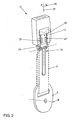
- the buckle 1 As mentioned above, is located in the Fig. 1 the buckle 1 in its non-use position I. To don the lap belt, the buckle 1 is folded up by the vehicle occupant in a position of use II by about 90 °, as shown in the Fig. 2 is shown. The folding up takes place counter to a build-up restoring force of the coil spring portions 25. In the illustrated position of use II, the support legs 17, 21 are located approximately in a common vertical plane.
- the two buckle support legs 17 are provided with the torsion sections 27 designed as turns.
- the torsion sections 27 reduce a torsional rigidity in an indicated direction of rotation 35 about a torsion axis 37.
- the torsion axis 37 extends centrally between the two buckle support legs 17 and transversely to the bending axis 19.
- the buckle 1 is rotated in its position of use II about the torsion axis 37 in the direction of rotation 35 by 90 °.
- the two torsion 27 can compensate for the rotation of the buckle 1 by the spring travel available to them at least partially.
Landscapes
- Engineering & Computer Science (AREA)
- Mechanical Engineering (AREA)
- Automotive Seat Belt Assembly (AREA)
- Clamps And Clips (AREA)
Abstract
Description
- Die Erfindung betrifft eine Gurtschloss-Befestigungsanordnung für ein Fahrzeug nach dem Oberbegriff des Patentanspruches 1.
- Bei einer hinteren Sitzbank eines Fahrzeuges kann üblicherweise ein Fahrzeuginsasse über einen mittleren Beckengurt gesichert sein. Das dem mittleren Beckengurt zugeordnete Gurtschloss kann an einer Gurtbandschlaufe angebunden sein, die aus einem Spalt zwischen dem hinteren Rand der Sitzbank und dem unteren Rand der Rückenlehne herausgeführt ist.
- Aus der
DE 202 00 271 U1 ist eine gattungsgemäße Gurtschloss-Befestigungsanordnung für ein Gurtschloss eines Fahrzeuges bekannt. Die Befestigungsanordnung weist ein im wesentlichen biegeschlaffes Befestigungsband auf, das das Gurtschloss mit dem Fahrzeugaufbau verbindet. Dem Befestigungsband ist ein federelastisches Stützteil zugeordnet, das das Gurtschloss um eine Biegeachse auf eine Sitzfläche im Fahrzeug vorspannt. Das Gurtschloss liegt daher in seiner Nichtgebrauchslage in einer definierten Ablageposition auf der Sitzbank. - Durch das, beispielsweise in das Befestigungsband eingenähte federelastische Stützteil ist dem Gurtschloss zwischen einer Gebrauchslage und der Nichtgebrauchslage ein vorgegebener Schwenkweg aufgezwungen. Zusätzliche, die Handhabung unterstützende Ausgleichsbewegungen des Gurtschlosses, etwa ein Verdrehen, die außerhalb dieses Schwenkweges liegen, sind demgegenüber erschwert.
- Aus der
DE 103 39 810 A1 ist ein weiterer Gurtschlosshalter für ein Fahrzeug bekannt, der auf ein Halteband aufweist, das mittels eines Einlegeteils ausgesteift ist. Das Einlegeteil ist durch einen Drahtfederkörper gebildet. - Die Aufgabe der Erfindung besteht darin, eine Gurtschloss-Befestigungsanordnung für ein Gurtschloss eines Fahrzeuges bereitzustellen, das betriebssicher am Fahrzeugaufbau gehaltert ist und eine bequeme Handhabung ermöglicht.
- Die Aufgabe ist durch die Merkmale des Patentanspruches 1 gelöst. Bevorzugte Weiterbildungen der Erfindung sind in den Unteransprüchen offenbart.
- Gemäß dem kennzeichnenden Teil des Patentanspruches 1 weist das federelastische Stützteil zumindest einen Torsionsabschnitt auf, der im Vergleich zum verbleibenden Stützteil eine reduzierte Torsionssteifigkeit aufweist. Das Gurtschloss kann daher nicht nur um die Biegeachse in die Gebrauchsstellung verbracht werden, sondern zusätzlich auch in einer Torsionsrichtung gedreht werden, wodurch dem Gurtschloss mit Bezug auf seine Bewegungsfähigkeit ein zusätzlicher Freiheitsgrad verliehen ist. Außerdem ist das federelastische Stützteil auf Torsion beanspruchbar, ohne dass es im Dauereinsatz zu einer Beschädigung bzw. Bruch des Stützteiles kommt.
- Bevorzugt kann der Torsionsabschnitt so gestaltet sein, dass eine Drehbewegung des Gurtschlosses um eine quer zur Biegeachse verlaufende Torsionsachse unterstützt ist. Bei einer Torsionsbeanspruchung des Stützteiles ist es von Vorteil, wenn der Torsionsabschnitt eine Rückstellkraft auf das Stützteil ausübt, wodurch das Stützteil selbsttätig in seine Ruhelage rückstellbar ist. Bevorzugt kann der Torsionsabschnitt daher elastisch nachgiebig gestaltet sein.
- In einer Ausführungsform kann der Torsionsabschnitt als gebogener Abschnitt im Stützteil ausgebildet sein, der die Torsionssteifigkeit des Stützteiles schwächt. Der Torsionsabschnitt kann dabei zumindest zu einer in etwa helixartigen Windung gebogen sein, die vorzugsweise quer zur Biegeachse des Stützteiles ausgerichtet sein kann.
- Das Stützteil kann beispielhaft mit dem biegeschlaffen Befestigungsband der Befestigungsanordnung vernäht sein. Außerdem kann es einen, dem Fahrzeugaufbau zugewandten Stützschenkel sowie einen, dazu elastisch verstellbaren, dem Gurtschloss zugewandten Stützschenkel aufweisen, die in einer Nichtgebrauchsstellung des Gurtschlosses zueinander abgewinkelt sind.
- Für eine leichtgängige Torsion des Gurtschlosses ist es von Vorteil, wenn der Torsionsabschnitt in dem, dem Gurtschloss zugewandten Stützschenkel des Stützteiles ausgebildet ist. Der andere, dem Fahrzeugaufbau zugewandte Stützschenkel des Stützteiles kann dabei zumindest teilweise zwischen dem hinteren Rand einer Fahrzeug-Sitzbank und dem unteren Rand einer zugeordneten Rückenlehne verklemmt sein.
- In einer bevorzugten Ausführungsform kann das Stützteil zwei, dem Gurtschloss zugewandte Stützschenkel aufweisen, zwischen denen in Richtung der Biegeachse der, dem Fahrzeugaufbau zugewandte Stützschenkel angeordnet ist. Die beiden, dem Gurtschloss zugewandten Stützschenkel können jeweils endseitige Einhängeabschnitte aufweisen, die in das Gurtschloss eingehängt sind. Die Torsionsachse verläuft daher nicht unmittelbar durch den Torsionsabschnitt. Vielmehr verläuft die Torsionsachse zwischen den beiden, dem Gurtschloss zugewandten Stützschenkel, in denen jeweils ein Torsionsabschnitt angeordnet sein kann.
- Hierbei ist es von Bedeutung, dass trotz einer Torsionsbeanspruchung sich das Stützteil nicht aus dem Gurtschloss aushängt. Dies kann erfindungsgemäß durch den Torsionsabschnitt gewährleistet sein, der zu einem Großteil einen Torsionsweg ausgleichen kann, wodurch die auf die Einhängeabschnitte wirkende Torsionsbeanspruchung reduziert ist.
- Für den Fall, dass der Torsionsabschnitt eine helixartige Windung ist, kann diese unter Vergrößerung einer Windungsluft auseinander gebogen werden und somit zumindest teilweise einen Torsionsweg aufnehmen.
- Bevorzugt ist es, wenn der Torsionsabschnitt mit geringer Baugröße gestaltet ist. Vor diesem Hintergrund kann der bevorzugt als Windung gebildete Torsionsabschnitt zumindest teilweise flach in Anlage mit dem Gurtschloss sein.
- Nachfolgend ist ein Ausführungsbeispiel der Erfindung anhand der beigefügten Figuren beschrieben.
- Es zeigen:
- Fig. 1
- in einer grob schematischen Darstellung ein Gurtschloss in seiner Nichtgebrauchslage, in der es auf einer Sitzfläche einer angedeuteten Sitzbank liegt;
- Fig. 2
- in einer Ansicht entsprechend der
Fig. 1 das Gurtschloss in einer Gebrauchslage, in der es um 90° nach oben geschwenkt ist; - Fig. 3
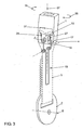
- in einer Ansicht entsprechend der
Fig. 2 das Gurtschloss bei einer Torsionsbeanspruchung um eine Torsionsachse; und - Fig. 4
- das erfindungsgemäße federelastische Stützteil in Alleinstellung.
- In der
Fig. 1 ist eine Gurtschloss-Befestigungsanordnung mit einem Gurtschloss 1 gezeigt. Das Gurtschloss 1 ist hier beispielhaft einem nicht dargestellten mittleren Beckengurt einer angedeuteten hinteren Sitzbank 3 zugeordnet. Das Gurtschloss 1 ist über ein Befestigungsband 5 am Fahrzeugaufbau verankert. Beispielhaft ist hier das Befestigungsband 5 eine Gurtbandschlaufe, die einerseits durch eine Öse eines Beschlagteils 7 geführt ist, das über eine angedeutete Verschraubung 8 am Fahrzeugaufbau befestigt ist. Andererseits ist die geschlossene Gurtbandschlaufe 5 durch eine Halteöse 9 des Gurtbandschlosses 1 geführt. - Die Gurtbandschlaufe 5 ist im wesentlichen biegeschlaff, das heißt mit nur geringer Formsteifigkeit versehen, und gemäß der
Fig. 1 zwischen einem hinteren Rand 11 der Sitzbank 3 und einem unteren Rand einer aus Übersichtlichkeitsgründen nicht gezeigten Rückenlehne in den Fahrzeuginnenraum geführt. - In die biegeschlaffe Gurtbandschlaufe 5 ist ein federelastisches Stützteil 13 integriert, das das Gurtschloss 1 in seiner Nichtgebrauchsstellung I gemäß der
Fig. 1 eine vordefinierte Ablageposition aufzwingt. Das Gurtschloss 1 liegt in dieser Ablageposition mit seiner flachen Seite auf einer Sitzfläche 15 der Sitzbank 3. - In der in der
Fig. 1 gezeigten Nichtgebrauchsstellung I ist das federelastische Stützteil 13 in seiner Ruhelage, in der es in etwa um 90° abgewinkelt ist. Das Stützteil 13 ist vorliegend als ein einteiliges Drahtbiegeteil gefertigt. Wie aus derFig. 4 hervorgeht, weist das Stützteil 13 zwei dem Gurtschloss 1 zugewandte Stützschenkel 17 aufweist, zwischen denen in Richtung einer Biegeachse 19 ein mittlerer, dem Beschlagteil 7 zugewandter Stützschenkel 21 angeordnet ist. Der Beschlagteil-Stützschenkel 21 ist U-förmig gestaltet. Die beiden Seitenstege 23 des U-förmigen Beschlagteil-Schenkels 21 gehen über Schraubenfederabschnitte 25 in die beiden seitlichen Gurtschloss-Schenkel 17 über. Die Windungen der beiden Federabschnitte 25 sind dabei fluchtend zur Biegeachse 19 ausgerichtet. In den beiden Gurtschloss-Schenkeln 17 ist jeweils ein erfindungsgemäßer Torsionsabschnitt 27 integriert, der hier beispielhaft als eine in den jeweiligen Stützschenkel 17 gebogene Windung ausgebildet ist. An ihren freien Enden weisen die beiden Gurtschloss-Stützschenkel 17 gemäß derFig. 4 jeweils umgebogene Einhängeabschnitte 29 auf, um das Stützteil 13 in eine gehäuseseitige Aussparung 31 des Gurtschlosses 1 einzuhängen. - In seiner Einbaulage ist das Stützteil 13 mit seinem U-förmigen Beschlagteil-Schenkel 21 sowie mit den beiden Federabschnitten 25 zwischen zwei Lagen der Gurtbandschlaufe 5 vernäht. Die beiden Gurtschloss-Schenkel 17 sind gemäß den
Fig. 1 bis 3 mit ihren jeweiligen Windungen 27 flach mit einer Auflagefläche 33 des Gurtbandschlosses in Anlage, während deren Einhängeabschnitte 29 einen unteren Rand der Aussparung 31 des Gurtschlosses 1 umgreifen. - Wie bereits oben erwähnt, befindet sich in der
Fig. 1 das Gurtschloss 1 in seiner Nichtgebrauchsstellung I. Zum Anlegen des Beckengurtes wird das Gurtschloss 1 vom Fahrzeuginsassen in eine Gebrauchsstellung II um etwa 90° hochgeklappt, wie es in derFig. 2 gezeigt ist. Das Hochklappen erfolgt entgegen einer sich aufbauenden Rückstellkraft der Schraubenfederabschnitte 25. In der gezeigten Gebrauchsstellung II befinden sich die Stützschenkel 17, 21 in etwa in einer gemeinsamen Vertikalebene. - Für einen einwandfreien Sitz des angelegten Befestigungsgurtes ist eine leichtgängige Lageanpassung des in seiner hochgeklappten Gebrauchsstellung II befindlichen Gurtschlosses 1 von Bedeutung. Für eine solche Lageanpassung sind die beiden Gurtschloss-Stützschenkel 17 mit den als Windungen ausgeführten Torsionsabschnitten 27 versehen. Die Torsionsabschnitte 27 reduzieren eine Torsionssteifigkeit in einer angedeuteten Drehrichtung 35 um eine Torsionsachse 37. Die Torsionsachse 37 erstreckt sich mittig zwischen den beiden Gurtschloss-Stützschenkel 17 sowie quer zur Biegeachse 19.
- In der
Fig. 3 ist das Gurtschloss 1 in seiner Gebrauchsstellung II um die Torsionsachse 37 in der Drehrichtung 35 um 90° gedreht. Durch ihre federnd nachgiebige Gestaltung als Feder-Windung können die beiden Torsionsabschnitte 27 den Drehweg des Gurtschlosses 1 durch den, ihnen zur Verfügung stehenden Federweg zumindest teilweise ausgleichen. - Dieser Ausgleich erfolgt gemäß der
Fig. 3 durch ein Auseinanderbiegen der in derFig. 3 gezeigten linken Windung, bei der sich eine Windungsluft n entsprechend vergrößert. Die in derFig. 3 gezeigte rechte Windung wird demgegenüber gegen die Auflagefläche 33 des Gurtschlosses 1 gedrückt und um einen Biegewinkel α auseinander gebogen. Durch die elastische Verformung der Torsionsabschnitte 27 der beiden Gurtschloss-Stützschenkel 17 wird eine entgegen der Verdrehung gerichtete weitere Rückstellkraft auf das Gurtschloss 1 ausgeübt. Ebenso wird durch die elastische Verformung der beiden Torsionsabschnitte 27 das Verdrehen des Gurtschlosses 1 auf eine Weise ausgeglichen, dass das Stützteil 13 betriebssicher in der Aussparung 31 eingehängt bleibt und nicht mit seinen Einhängeabschnitten 29 aus der Gurtschloss-Aussparung 31 herausspringt. Die beiden Torsionsabschnitte 27 des Stützteiles 13 können daher bei einer durch Verdrehen um die Torsionsachse 37 aufgebrachten Biegespannung ausgleichen, wodurch auch im Dauereinsatz ein Ermüdungsbruch der beiden Gurtschloss-Stützschenkel 17 ausgeschlossen ist. -
- 1
- Gurtschloss
- 3
- Sitzbank
- 5
- Gurtband
- 7
- Beschlagteil
- 8
- Verschraubung
- 9
- Halteöse
- 11
- Rand
- 13
- federelastisches Stützteil
- 15
- Sitzfläche
- 17
- Gurtschloss-Stützschenkel
- 19
- Biegeachse
- 21
- Beschlagteil-Stützschenkel
- 23
- Seitenstege
- 25
- Federabschnitte
- 27
- Torsionsabschnitte
- 29
- Einhängeabschnitte
- 31
- Aussparung
- 33
- Auflagefläche
- 35
- Drehrichtung
- 37
- Torsionsachse
- n
- Windungsluft
- α
- Biegewinkel
- I
- Nichtgebrauchsstellung
- II
- Gebrauchsstellung
Claims (14)
- Gurtschloss-Befestigungsanordnung für ein Gurtschloss (1) eines Fahrzeuges, mit einem im wesentlichen biegeschlaffen Befestigungsband (5), das das Gurtschloss (1) mit einem Fahrzeugaufbau verbindet, und einem federelastischen Stützteil (13), das das Gurtschloss (1) um eine Biegeachse (19) auf einer Sitzfläche (15) im Fahrzeug vorpositioniert, dadurch gekennzeichnet, dass das Stützteil (13) zumindest einen Torsionsabschnitt (27) aufweist, der im Vergleich zum verbleibenden Stützteil (13) eine reduzierte Torsionssteifigkeit aufweist.
- Befestigungsanordnung nach Anspruch 1, dadurch gekennzeichnet, dass der Torsionsabschnitt (27) um eine quer zur Biegeachse (19) verlaufende Torsionsachse (37) nachgiebig ist.
- Befestigungsanordnung nach Anspruch 1 oder 2, dadurch gekennzeichnet, dass das Stützteil (13) zumindest einen dem Fahrzeugaufbau zugewandten Stützschenkel (21) und zumindest einen dem Gurtschloss (1) zugewandten Stützschenkel (17) aufweist, die vorzugsweise in einer Nichtgebrauchsstellung (I) des Gurtschlosses (1) zueinander abgewinkelt sind.
- Befestigungsanordnung nach Anspruch 3, dadurch gekennzeichnet, dass der Torsionsabschnitt (27) in dem, dem Gurtschloss (1) zugewandten Stützschenkel (27) des Stützteils (13) ausgebildet ist.
- Befestigungsanordnung nach einem der vorhergehenden Ansprüche, dadurch gekennzeichnet, dass das Stützteil (13) ein Drahtbiegeteil ist.
- Befestigungsanordnung nach einem der vorhergehenden Ansprüche, dadurch gekennzeichnet, dass der Torsionsabschnitt (27) als gebogener Abschnitt im Stützteil (13) ausgebildet ist, der die Torsionssteifigkeit des Stützteils (13) schwächt.
- Befestigungsanordnung nach einem der vorhergehenden Ansprüche, dadurch gekennzeichnet, dass der Torsionsabschnitt (27) bei einer Torsion des Stützteils (13) eine Rückstellkraft auf das Stützteil (13) ausübt, und insbesondere elastisch nachgiebig gebildet ist.
- Befestigungsanordnung nach einem der vorhergehenden Ansprüche, dadurch gekennzeichnet, dass der Torsionsabschnitt (27) zumindest eine Windung aufweist, die vorzugsweise quer zur Biegeachse (19) des Stützteils (13) ausgerichtet ist.
- Befestigungsanordnung nach einem der vorhergehenden Ansprüche 3 bis 8, dadurch gekennzeichnet, dass die beide Stützschenkel (17, 21) des Stützteiles (13) über zumindest eine Windung verbunden sind, die fluchtend zur Biegeachse (19) des Stützteils (13) ausgerichtet ist.
- Befestigungsanordnung nach Anspruch 8 oder 9, dadurch gekennzeichnet, dass die Windung des Torsionsabschnittes (27) zumindest teilweise außenseitig in Anlage mit dem Gurtschloss (1) ist.
- Befestigungsanordnung nach einem der Ansprüche 3 bis 10, dadurch gekennzeichnet, dass das Stützteil (13) zwei, dem Gurtschloss (1) zugewandte Stützschenkel (17) aufweist, zwischen denen in Richtung der Biegeachse (19) der dem Fahrzeugaufbau zugewandte Stützschenkel (21) angeordnet ist.
- Befestigungsanordnung nach Anspruch 11, dadurch gekennzeichnet, dass zwischen den beiden, dem Gurtschloss (1) zugewandten Stützschenkel (17) die Torsionsachse (37) verläuft.
- Befestigungsanordnung nach einem der vorhergehenden Ansprüche, dadurch gekennzeichnet, dass der zumindest eine, dem Gurtschloss (1) zugewandte Stützschenkel (17) des Stützteiles (13) endseitig einen Einhängeabschnitt (29) zum Einhängen in das Gurtschloss (1) aufweist.
- Befestigungsanordnung nach einem der Ansprüche 8 bis 13, dadurch gekennzeichnet, dass bei einer Torsion des Stützteils (13) die Windung des Torsionsabschnittes (27) unter Vergrößerung einer Windungsluft (n) auseinanderbiegbar ist.
Applications Claiming Priority (1)
| Application Number | Priority Date | Filing Date | Title |
|---|---|---|---|
| DE102008025743A DE102008025743A1 (de) | 2008-05-29 | 2008-05-29 | Gurtschloss-Befestigungsanordnung für ein Fahrzeug |
Publications (3)
| Publication Number | Publication Date |
|---|---|
| EP2127962A2 true EP2127962A2 (de) | 2009-12-02 |
| EP2127962A3 EP2127962A3 (de) | 2011-05-25 |
| EP2127962B1 EP2127962B1 (de) | 2012-10-03 |
Family
ID=40957612
Family Applications (1)
| Application Number | Title | Priority Date | Filing Date |
|---|---|---|---|
| EP20090005024 Not-in-force EP2127962B1 (de) | 2008-05-29 | 2009-04-04 | Gurtschloss-Befestigungsanordnung für ein Fahrzeug |
Country Status (2)
| Country | Link |
|---|---|
| EP (1) | EP2127962B1 (de) |
| DE (1) | DE102008025743A1 (de) |
Cited By (2)
| Publication number | Priority date | Publication date | Assignee | Title |
|---|---|---|---|---|
| CN111819115A (zh) * | 2018-02-22 | 2020-10-23 | 大众汽车股份公司 | 用于车辆座椅的安全带装置 |
| US10974689B2 (en) * | 2019-02-27 | 2021-04-13 | Trw Vehicle Safety Systems Inc. | Biasing arrangement for seatbelt buckle |
Citations (2)
| Publication number | Priority date | Publication date | Assignee | Title |
|---|---|---|---|---|
| DE20200271U1 (de) | 2002-01-09 | 2002-05-16 | TRW Occupant Restraint Systems GmbH & Co. KG, 73553 Alfdorf | Gurtschloß-Befestigungsvorrichtung |
| DE10339810A1 (de) | 2002-08-30 | 2004-03-25 | Volkswagen Ag | Gurtschlosshalter für ein Fahrzeug, vorzugsweise für ein Kraftfahrzeug |
Family Cites Families (2)
| Publication number | Priority date | Publication date | Assignee | Title |
|---|---|---|---|---|
| DE29700908U1 (de) * | 1997-01-20 | 1997-05-15 | Trw Occupant Restraint Systems Gmbh, 73551 Alfdorf | Gurtschloß mit Befestigungsbeschlag |
| KR101005249B1 (ko) * | 2002-07-19 | 2011-01-04 | 오토리브 디벨로프먼트 에이비 | 좌석 벨트 버클 조립체 |
-
2008
- 2008-05-29 DE DE102008025743A patent/DE102008025743A1/de not_active Withdrawn
-
2009
- 2009-04-04 EP EP20090005024 patent/EP2127962B1/de not_active Not-in-force
Patent Citations (2)
| Publication number | Priority date | Publication date | Assignee | Title |
|---|---|---|---|---|
| DE20200271U1 (de) | 2002-01-09 | 2002-05-16 | TRW Occupant Restraint Systems GmbH & Co. KG, 73553 Alfdorf | Gurtschloß-Befestigungsvorrichtung |
| DE10339810A1 (de) | 2002-08-30 | 2004-03-25 | Volkswagen Ag | Gurtschlosshalter für ein Fahrzeug, vorzugsweise für ein Kraftfahrzeug |
Cited By (2)
| Publication number | Priority date | Publication date | Assignee | Title |
|---|---|---|---|---|
| CN111819115A (zh) * | 2018-02-22 | 2020-10-23 | 大众汽车股份公司 | 用于车辆座椅的安全带装置 |
| US10974689B2 (en) * | 2019-02-27 | 2021-04-13 | Trw Vehicle Safety Systems Inc. | Biasing arrangement for seatbelt buckle |
Also Published As
| Publication number | Publication date |
|---|---|
| EP2127962B1 (de) | 2012-10-03 |
| EP2127962A3 (de) | 2011-05-25 |
| DE102008025743A1 (de) | 2009-12-03 |
Similar Documents
| Publication | Publication Date | Title |
|---|---|---|
| EP3045347B1 (de) | Lagervorrichtung und kopfstütze | |
| DE202019100137U1 (de) | Sicherheitsgurtsteckzungenbaugruppe mit Verriegelungsmechanismus | |
| DE202009013518U1 (de) | Anordnung eines Kindersitzes und einer Befestigungsvorrichtung | |
| EP2132057A1 (de) | An einem aus federelementen bestehenden stützgerüst festgelegter sicherheitssitz | |
| DE102011051300A1 (de) | Vorrichtung zum Verhindern von Nackenverletzungen zur Verwendung bei einem Fahrzeugsitz | |
| DE102008034958B3 (de) | Gurtschloss | |
| EP2127962B1 (de) | Gurtschloss-Befestigungsanordnung für ein Fahrzeug | |
| DE20200271U1 (de) | Gurtschloß-Befestigungsvorrichtung | |
| DE2264509B2 (de) | Gelenkbeschlag für Kraftfahrzeugsitze | |
| DE102010023662A1 (de) | Befestigungsanordnung für einen Gurtführungsbügel eines Sicherheitsgurtes | |
| DE102021213499B4 (de) | Sicherheitsgurteinrichtung für einen Fahrzeugsitz | |
| WO2013034254A2 (de) | Befestigungsvorrichtung für einen kindersitz in einem kraftfahrzeug | |
| WO2014015971A1 (de) | Stützvorrichtung für einen sitz und damit ausgerüsteter fahrzeugsitz | |
| DE202019105528U1 (de) | Sitzbezugselement für einen Fahrzeugsitz, Verwendung eines solchen Sitzbezugselements und Fahrzeugsitz | |
| DE102018123665B4 (de) | Gurtbefestigungsanordnung | |
| DE10339810B4 (de) | Gurtschlosshalter für ein Fahrzeug, vorzugsweise für ein Kraftfahrzeug | |
| DE102010031202B4 (de) | Sitzuntergestell für ein Kraftfahrzeug | |
| EP1507684A1 (de) | Halteteil zur anbringung von metallrahmennetzen, insbesondere von kofferraumseitennetzen | |
| DE102018206398B4 (de) | Führungselement mit Befestigung an einem Sitzkissen, Sitzkissen, Fahrzeugsitz und Fahrzeug mit einem solchen Führungselement | |
| DE102022114164B4 (de) | Gurtaufroller mit einer elektrisch betätigbaren Blockiereinrichtung | |
| DE102019004287A1 (de) | Verankerungsanordnung zum Verankern eines Gurtverankerungselementes für einen Sicherheitsgurt an einem Fahrzeugbauteil | |
| DE102020106684A1 (de) | Halterung zum Halten einer Verkleidung an einer Sitzstruktur und Sitzbraugruppe mit einer Sitzstruktur und einer solchen Halterung | |
| DE102015121118B4 (de) | Verriegelungsmechanismus für ein Sitzkissen | |
| DE102014204990B4 (de) | Sicherheitsgurteinrichtung für ein Fahrzeug | |
| DE102006019751B4 (de) | Gurtzunge |
Legal Events
| Date | Code | Title | Description |
|---|---|---|---|
| PUAI | Public reference made under article 153(3) epc to a published international application that has entered the european phase |
Free format text: ORIGINAL CODE: 0009012 |
|
| AK | Designated contracting states |
Kind code of ref document: A2 Designated state(s): AT BE BG CH CY CZ DE DK EE ES FI FR GB GR HR HU IE IS IT LI LT LU LV MC MK MT NL NO PL PT RO SE SI SK TR |
|
| PUAL | Search report despatched |
Free format text: ORIGINAL CODE: 0009013 |
|
| AK | Designated contracting states |
Kind code of ref document: A3 Designated state(s): AT BE BG CH CY CZ DE DK EE ES FI FR GB GR HR HU IE IS IT LI LT LU LV MC MK MT NL NO PL PT RO SE SI SK TR |
|
| AX | Request for extension of the european patent |
Extension state: AL BA RS |
|
| 17P | Request for examination filed |
Effective date: 20111125 |
|
| GRAP | Despatch of communication of intention to grant a patent |
Free format text: ORIGINAL CODE: EPIDOSNIGR1 |
|
| RAP1 | Party data changed (applicant data changed or rights of an application transferred) |
Owner name: VOLKSWAGEN AKTIENGESELLSCHAFT |
|
| GRAS | Grant fee paid |
Free format text: ORIGINAL CODE: EPIDOSNIGR3 |
|
| GRAA | (expected) grant |
Free format text: ORIGINAL CODE: 0009210 |
|
| AK | Designated contracting states |
Kind code of ref document: B1 Designated state(s): AT BE BG CH CY CZ DE DK EE ES FI FR GB GR HR HU IE IS IT LI LT LU LV MC MK MT NL NO PL PT RO SE SI SK TR |
|
| REG | Reference to a national code |
Ref country code: GB Ref legal event code: FG4D Free format text: NOT ENGLISH |
|
| REG | Reference to a national code |
Ref country code: AT Ref legal event code: REF Ref document number: 577821 Country of ref document: AT Kind code of ref document: T Effective date: 20121015 Ref country code: CH Ref legal event code: EP |
|
| REG | Reference to a national code |
Ref country code: IE Ref legal event code: FG4D Free format text: LANGUAGE OF EP DOCUMENT: GERMAN |
|
| REG | Reference to a national code |
Ref country code: DE Ref legal event code: R096 Ref document number: 502009004931 Country of ref document: DE Effective date: 20121206 |
|
| PG25 | Lapsed in a contracting state [announced via postgrant information from national office to epo] |
Ref country code: SI Free format text: LAPSE BECAUSE OF FAILURE TO SUBMIT A TRANSLATION OF THE DESCRIPTION OR TO PAY THE FEE WITHIN THE PRESCRIBED TIME-LIMIT Effective date: 20121003 |
|
| REG | Reference to a national code |
Ref country code: NL Ref legal event code: VDEP Effective date: 20121003 |
|
| REG | Reference to a national code |
Ref country code: LT Ref legal event code: MG4D |
|
| PG25 | Lapsed in a contracting state [announced via postgrant information from national office to epo] |
Ref country code: NO Free format text: LAPSE BECAUSE OF FAILURE TO SUBMIT A TRANSLATION OF THE DESCRIPTION OR TO PAY THE FEE WITHIN THE PRESCRIBED TIME-LIMIT Effective date: 20130103 Ref country code: SE Free format text: LAPSE BECAUSE OF FAILURE TO SUBMIT A TRANSLATION OF THE DESCRIPTION OR TO PAY THE FEE WITHIN THE PRESCRIBED TIME-LIMIT Effective date: 20121003 Ref country code: FI Free format text: LAPSE BECAUSE OF FAILURE TO SUBMIT A TRANSLATION OF THE DESCRIPTION OR TO PAY THE FEE WITHIN THE PRESCRIBED TIME-LIMIT Effective date: 20121003 Ref country code: LT Free format text: LAPSE BECAUSE OF FAILURE TO SUBMIT A TRANSLATION OF THE DESCRIPTION OR TO PAY THE FEE WITHIN THE PRESCRIBED TIME-LIMIT Effective date: 20121003 Ref country code: NL Free format text: LAPSE BECAUSE OF FAILURE TO SUBMIT A TRANSLATION OF THE DESCRIPTION OR TO PAY THE FEE WITHIN THE PRESCRIBED TIME-LIMIT Effective date: 20121003 Ref country code: IS Free format text: LAPSE BECAUSE OF FAILURE TO SUBMIT A TRANSLATION OF THE DESCRIPTION OR TO PAY THE FEE WITHIN THE PRESCRIBED TIME-LIMIT Effective date: 20130203 Ref country code: HR Free format text: LAPSE BECAUSE OF FAILURE TO SUBMIT A TRANSLATION OF THE DESCRIPTION OR TO PAY THE FEE WITHIN THE PRESCRIBED TIME-LIMIT Effective date: 20121003 Ref country code: ES Free format text: LAPSE BECAUSE OF FAILURE TO SUBMIT A TRANSLATION OF THE DESCRIPTION OR TO PAY THE FEE WITHIN THE PRESCRIBED TIME-LIMIT Effective date: 20130114 |
|
| PG25 | Lapsed in a contracting state [announced via postgrant information from national office to epo] |
Ref country code: PL Free format text: LAPSE BECAUSE OF FAILURE TO SUBMIT A TRANSLATION OF THE DESCRIPTION OR TO PAY THE FEE WITHIN THE PRESCRIBED TIME-LIMIT Effective date: 20121003 Ref country code: PT Free format text: LAPSE BECAUSE OF FAILURE TO SUBMIT A TRANSLATION OF THE DESCRIPTION OR TO PAY THE FEE WITHIN THE PRESCRIBED TIME-LIMIT Effective date: 20130204 Ref country code: GR Free format text: LAPSE BECAUSE OF FAILURE TO SUBMIT A TRANSLATION OF THE DESCRIPTION OR TO PAY THE FEE WITHIN THE PRESCRIBED TIME-LIMIT Effective date: 20130104 Ref country code: CY Free format text: LAPSE BECAUSE OF FAILURE TO SUBMIT A TRANSLATION OF THE DESCRIPTION OR TO PAY THE FEE WITHIN THE PRESCRIBED TIME-LIMIT Effective date: 20121003 Ref country code: LV Free format text: LAPSE BECAUSE OF FAILURE TO SUBMIT A TRANSLATION OF THE DESCRIPTION OR TO PAY THE FEE WITHIN THE PRESCRIBED TIME-LIMIT Effective date: 20121003 |
|
| PG25 | Lapsed in a contracting state [announced via postgrant information from national office to epo] |
Ref country code: CZ Free format text: LAPSE BECAUSE OF FAILURE TO SUBMIT A TRANSLATION OF THE DESCRIPTION OR TO PAY THE FEE WITHIN THE PRESCRIBED TIME-LIMIT Effective date: 20121003 Ref country code: DK Free format text: LAPSE BECAUSE OF FAILURE TO SUBMIT A TRANSLATION OF THE DESCRIPTION OR TO PAY THE FEE WITHIN THE PRESCRIBED TIME-LIMIT Effective date: 20121003 Ref country code: SK Free format text: LAPSE BECAUSE OF FAILURE TO SUBMIT A TRANSLATION OF THE DESCRIPTION OR TO PAY THE FEE WITHIN THE PRESCRIBED TIME-LIMIT Effective date: 20121003 Ref country code: EE Free format text: LAPSE BECAUSE OF FAILURE TO SUBMIT A TRANSLATION OF THE DESCRIPTION OR TO PAY THE FEE WITHIN THE PRESCRIBED TIME-LIMIT Effective date: 20121003 Ref country code: BG Free format text: LAPSE BECAUSE OF FAILURE TO SUBMIT A TRANSLATION OF THE DESCRIPTION OR TO PAY THE FEE WITHIN THE PRESCRIBED TIME-LIMIT Effective date: 20130103 |
|
| PLBE | No opposition filed within time limit |
Free format text: ORIGINAL CODE: 0009261 |
|
| STAA | Information on the status of an ep patent application or granted ep patent |
Free format text: STATUS: NO OPPOSITION FILED WITHIN TIME LIMIT |
|
| PG25 | Lapsed in a contracting state [announced via postgrant information from national office to epo] |
Ref country code: RO Free format text: LAPSE BECAUSE OF FAILURE TO SUBMIT A TRANSLATION OF THE DESCRIPTION OR TO PAY THE FEE WITHIN THE PRESCRIBED TIME-LIMIT Effective date: 20121003 Ref country code: IT Free format text: LAPSE BECAUSE OF FAILURE TO SUBMIT A TRANSLATION OF THE DESCRIPTION OR TO PAY THE FEE WITHIN THE PRESCRIBED TIME-LIMIT Effective date: 20121003 |
|
| 26N | No opposition filed |
Effective date: 20130704 |
|
| BERE | Be: lapsed |
Owner name: VOLKSWAGEN A.G. Effective date: 20130430 |
|
| REG | Reference to a national code |
Ref country code: DE Ref legal event code: R097 Ref document number: 502009004931 Country of ref document: DE Effective date: 20130704 |
|
| PG25 | Lapsed in a contracting state [announced via postgrant information from national office to epo] |
Ref country code: MC Free format text: LAPSE BECAUSE OF FAILURE TO SUBMIT A TRANSLATION OF THE DESCRIPTION OR TO PAY THE FEE WITHIN THE PRESCRIBED TIME-LIMIT Effective date: 20121003 |
|
| REG | Reference to a national code |
Ref country code: CH Ref legal event code: PL |
|
| REG | Reference to a national code |
Ref country code: IE Ref legal event code: MM4A |
|
| PG25 | Lapsed in a contracting state [announced via postgrant information from national office to epo] |
Ref country code: CH Free format text: LAPSE BECAUSE OF NON-PAYMENT OF DUE FEES Effective date: 20130430 Ref country code: BE Free format text: LAPSE BECAUSE OF NON-PAYMENT OF DUE FEES Effective date: 20130430 Ref country code: LI Free format text: LAPSE BECAUSE OF NON-PAYMENT OF DUE FEES Effective date: 20130430 |
|
| PG25 | Lapsed in a contracting state [announced via postgrant information from national office to epo] |
Ref country code: IE Free format text: LAPSE BECAUSE OF NON-PAYMENT OF DUE FEES Effective date: 20130404 |
|
| PG25 | Lapsed in a contracting state [announced via postgrant information from national office to epo] |
Ref country code: MT Free format text: LAPSE BECAUSE OF FAILURE TO SUBMIT A TRANSLATION OF THE DESCRIPTION OR TO PAY THE FEE WITHIN THE PRESCRIBED TIME-LIMIT Effective date: 20121003 |
|
| REG | Reference to a national code |
Ref country code: AT Ref legal event code: MM01 Ref document number: 577821 Country of ref document: AT Kind code of ref document: T Effective date: 20140404 |
|
| PG25 | Lapsed in a contracting state [announced via postgrant information from national office to epo] |
Ref country code: TR Free format text: LAPSE BECAUSE OF FAILURE TO SUBMIT A TRANSLATION OF THE DESCRIPTION OR TO PAY THE FEE WITHIN THE PRESCRIBED TIME-LIMIT Effective date: 20121003 |
|
| PG25 | Lapsed in a contracting state [announced via postgrant information from national office to epo] |
Ref country code: MK Free format text: LAPSE BECAUSE OF FAILURE TO SUBMIT A TRANSLATION OF THE DESCRIPTION OR TO PAY THE FEE WITHIN THE PRESCRIBED TIME-LIMIT Effective date: 20121003 Ref country code: HU Free format text: LAPSE BECAUSE OF FAILURE TO SUBMIT A TRANSLATION OF THE DESCRIPTION OR TO PAY THE FEE WITHIN THE PRESCRIBED TIME-LIMIT; INVALID AB INITIO Effective date: 20090404 Ref country code: LU Free format text: LAPSE BECAUSE OF NON-PAYMENT OF DUE FEES Effective date: 20130404 |
|
| PG25 | Lapsed in a contracting state [announced via postgrant information from national office to epo] |
Ref country code: AT Free format text: LAPSE BECAUSE OF NON-PAYMENT OF DUE FEES Effective date: 20140404 |
|
| REG | Reference to a national code |
Ref country code: FR Ref legal event code: PLFP Year of fee payment: 8 |
|
| REG | Reference to a national code |
Ref country code: FR Ref legal event code: PLFP Year of fee payment: 9 |
|
| PGFP | Annual fee paid to national office [announced via postgrant information from national office to epo] |
Ref country code: GB Payment date: 20170427 Year of fee payment: 9 Ref country code: FR Payment date: 20170428 Year of fee payment: 9 |
|
| GBPC | Gb: european patent ceased through non-payment of renewal fee |
Effective date: 20180404 |
|
| PG25 | Lapsed in a contracting state [announced via postgrant information from national office to epo] |
Ref country code: GB Free format text: LAPSE BECAUSE OF NON-PAYMENT OF DUE FEES Effective date: 20180404 |
|
| PG25 | Lapsed in a contracting state [announced via postgrant information from national office to epo] |
Ref country code: FR Free format text: LAPSE BECAUSE OF NON-PAYMENT OF DUE FEES Effective date: 20180430 |
|
| P01 | Opt-out of the competence of the unified patent court (upc) registered |
Effective date: 20230523 |
|
| PGFP | Annual fee paid to national office [announced via postgrant information from national office to epo] |
Ref country code: DE Payment date: 20230430 Year of fee payment: 15 |
|
| REG | Reference to a national code |
Ref country code: DE Ref legal event code: R119 Ref document number: 502009004931 Country of ref document: DE |
|
| PG25 | Lapsed in a contracting state [announced via postgrant information from national office to epo] |
Ref country code: DE Free format text: LAPSE BECAUSE OF NON-PAYMENT OF DUE FEES Effective date: 20241105 |
|
| PG25 | Lapsed in a contracting state [announced via postgrant information from national office to epo] |
Ref country code: DE Free format text: LAPSE BECAUSE OF NON-PAYMENT OF DUE FEES Effective date: 20241105 |