EP2126371B1 - Ensemble vanne - Google Patents
Ensemble vanne Download PDFInfo
- Publication number
- EP2126371B1 EP2126371B1 EP20080707119 EP08707119A EP2126371B1 EP 2126371 B1 EP2126371 B1 EP 2126371B1 EP 20080707119 EP20080707119 EP 20080707119 EP 08707119 A EP08707119 A EP 08707119A EP 2126371 B1 EP2126371 B1 EP 2126371B1
- Authority
- EP
- European Patent Office
- Prior art keywords
- valve
- control
- pressure
- additional
- line
- Prior art date
- Legal status (The legal status is an assumption and is not a legal conclusion. Google has not performed a legal analysis and makes no representation as to the accuracy of the status listed.)
- Not-in-force
Links
Images
Classifications
-
- F—MECHANICAL ENGINEERING; LIGHTING; HEATING; WEAPONS; BLASTING
- F15—FLUID-PRESSURE ACTUATORS; HYDRAULICS OR PNEUMATICS IN GENERAL
- F15B—SYSTEMS ACTING BY MEANS OF FLUIDS IN GENERAL; FLUID-PRESSURE ACTUATORS, e.g. SERVOMOTORS; DETAILS OF FLUID-PRESSURE SYSTEMS, NOT OTHERWISE PROVIDED FOR
- F15B11/00—Servomotor systems without provision for follow-up action; Circuits therefor
- F15B11/02—Systems essentially incorporating special features for controlling the speed or actuating force of an output member
- F15B11/04—Systems essentially incorporating special features for controlling the speed or actuating force of an output member for controlling the speed
- F15B11/05—Systems essentially incorporating special features for controlling the speed or actuating force of an output member for controlling the speed specially adapted to maintain constant speed, e.g. pressure-compensated, load-responsive
-
- E—FIXED CONSTRUCTIONS
- E02—HYDRAULIC ENGINEERING; FOUNDATIONS; SOIL SHIFTING
- E02F—DREDGING; SOIL-SHIFTING
- E02F9/00—Component parts of dredgers or soil-shifting machines, not restricted to one of the kinds covered by groups E02F3/00 - E02F7/00
- E02F9/20—Drives; Control devices
- E02F9/22—Hydraulic or pneumatic drives
- E02F9/2278—Hydraulic circuits
- E02F9/2285—Pilot-operated systems
-
- F—MECHANICAL ENGINEERING; LIGHTING; HEATING; WEAPONS; BLASTING
- F15—FLUID-PRESSURE ACTUATORS; HYDRAULICS OR PNEUMATICS IN GENERAL
- F15B—SYSTEMS ACTING BY MEANS OF FLUIDS IN GENERAL; FLUID-PRESSURE ACTUATORS, e.g. SERVOMOTORS; DETAILS OF FLUID-PRESSURE SYSTEMS, NOT OTHERWISE PROVIDED FOR
- F15B11/00—Servomotor systems without provision for follow-up action; Circuits therefor
- F15B11/16—Servomotor systems without provision for follow-up action; Circuits therefor with two or more servomotors
- F15B11/161—Servomotor systems without provision for follow-up action; Circuits therefor with two or more servomotors with sensing of servomotor demand or load
- F15B11/163—Servomotor systems without provision for follow-up action; Circuits therefor with two or more servomotors with sensing of servomotor demand or load for sharing the pump output equally amongst users or groups of users, e.g. using anti-saturation, pressure compensation
-
- F—MECHANICAL ENGINEERING; LIGHTING; HEATING; WEAPONS; BLASTING
- F15—FLUID-PRESSURE ACTUATORS; HYDRAULICS OR PNEUMATICS IN GENERAL
- F15B—SYSTEMS ACTING BY MEANS OF FLUIDS IN GENERAL; FLUID-PRESSURE ACTUATORS, e.g. SERVOMOTORS; DETAILS OF FLUID-PRESSURE SYSTEMS, NOT OTHERWISE PROVIDED FOR
- F15B2211/00—Circuits for servomotor systems
- F15B2211/20—Fluid pressure source, e.g. accumulator or variable axial piston pump
- F15B2211/205—Systems with pumps
- F15B2211/2053—Type of pump
- F15B2211/20538—Type of pump constant capacity
-
- F—MECHANICAL ENGINEERING; LIGHTING; HEATING; WEAPONS; BLASTING
- F15—FLUID-PRESSURE ACTUATORS; HYDRAULICS OR PNEUMATICS IN GENERAL
- F15B—SYSTEMS ACTING BY MEANS OF FLUIDS IN GENERAL; FLUID-PRESSURE ACTUATORS, e.g. SERVOMOTORS; DETAILS OF FLUID-PRESSURE SYSTEMS, NOT OTHERWISE PROVIDED FOR
- F15B2211/00—Circuits for servomotor systems
- F15B2211/30—Directional control
- F15B2211/305—Directional control characterised by the type of valves
- F15B2211/30525—Directional control valves, e.g. 4/3-directional control valve
- F15B2211/3053—In combination with a pressure compensating valve
- F15B2211/30535—In combination with a pressure compensating valve the pressure compensating valve is arranged between pressure source and directional control valve
-
- F—MECHANICAL ENGINEERING; LIGHTING; HEATING; WEAPONS; BLASTING
- F15—FLUID-PRESSURE ACTUATORS; HYDRAULICS OR PNEUMATICS IN GENERAL
- F15B—SYSTEMS ACTING BY MEANS OF FLUIDS IN GENERAL; FLUID-PRESSURE ACTUATORS, e.g. SERVOMOTORS; DETAILS OF FLUID-PRESSURE SYSTEMS, NOT OTHERWISE PROVIDED FOR
- F15B2211/00—Circuits for servomotor systems
- F15B2211/30—Directional control
- F15B2211/32—Directional control characterised by the type of actuation
- F15B2211/329—Directional control characterised by the type of actuation actuated by fluid pressure
-
- F—MECHANICAL ENGINEERING; LIGHTING; HEATING; WEAPONS; BLASTING
- F15—FLUID-PRESSURE ACTUATORS; HYDRAULICS OR PNEUMATICS IN GENERAL
- F15B—SYSTEMS ACTING BY MEANS OF FLUIDS IN GENERAL; FLUID-PRESSURE ACTUATORS, e.g. SERVOMOTORS; DETAILS OF FLUID-PRESSURE SYSTEMS, NOT OTHERWISE PROVIDED FOR
- F15B2211/00—Circuits for servomotor systems
- F15B2211/40—Flow control
- F15B2211/405—Flow control characterised by the type of flow control means or valve
- F15B2211/40553—Flow control characterised by the type of flow control means or valve with pressure compensating valves
- F15B2211/40561—Flow control characterised by the type of flow control means or valve with pressure compensating valves the pressure compensating valve arranged upstream of the flow control means
-
- F—MECHANICAL ENGINEERING; LIGHTING; HEATING; WEAPONS; BLASTING
- F15—FLUID-PRESSURE ACTUATORS; HYDRAULICS OR PNEUMATICS IN GENERAL
- F15B—SYSTEMS ACTING BY MEANS OF FLUIDS IN GENERAL; FLUID-PRESSURE ACTUATORS, e.g. SERVOMOTORS; DETAILS OF FLUID-PRESSURE SYSTEMS, NOT OTHERWISE PROVIDED FOR
- F15B2211/00—Circuits for servomotor systems
- F15B2211/60—Circuit components or control therefor
- F15B2211/605—Load sensing circuits
- F15B2211/6051—Load sensing circuits having valve means between output member and the load sensing circuit
- F15B2211/6054—Load sensing circuits having valve means between output member and the load sensing circuit using shuttle valves
-
- F—MECHANICAL ENGINEERING; LIGHTING; HEATING; WEAPONS; BLASTING
- F15—FLUID-PRESSURE ACTUATORS; HYDRAULICS OR PNEUMATICS IN GENERAL
- F15B—SYSTEMS ACTING BY MEANS OF FLUIDS IN GENERAL; FLUID-PRESSURE ACTUATORS, e.g. SERVOMOTORS; DETAILS OF FLUID-PRESSURE SYSTEMS, NOT OTHERWISE PROVIDED FOR
- F15B2211/00—Circuits for servomotor systems
- F15B2211/60—Circuit components or control therefor
- F15B2211/605—Load sensing circuits
- F15B2211/6051—Load sensing circuits having valve means between output member and the load sensing circuit
- F15B2211/6055—Load sensing circuits having valve means between output member and the load sensing circuit using pressure relief valves
-
- F—MECHANICAL ENGINEERING; LIGHTING; HEATING; WEAPONS; BLASTING
- F15—FLUID-PRESSURE ACTUATORS; HYDRAULICS OR PNEUMATICS IN GENERAL
- F15B—SYSTEMS ACTING BY MEANS OF FLUIDS IN GENERAL; FLUID-PRESSURE ACTUATORS, e.g. SERVOMOTORS; DETAILS OF FLUID-PRESSURE SYSTEMS, NOT OTHERWISE PROVIDED FOR
- F15B2211/00—Circuits for servomotor systems
- F15B2211/60—Circuit components or control therefor
- F15B2211/63—Electronic controllers
- F15B2211/6303—Electronic controllers using input signals
- F15B2211/6306—Electronic controllers using input signals representing a pressure
- F15B2211/6313—Electronic controllers using input signals representing a pressure the pressure being a load pressure
-
- F—MECHANICAL ENGINEERING; LIGHTING; HEATING; WEAPONS; BLASTING
- F15—FLUID-PRESSURE ACTUATORS; HYDRAULICS OR PNEUMATICS IN GENERAL
- F15B—SYSTEMS ACTING BY MEANS OF FLUIDS IN GENERAL; FLUID-PRESSURE ACTUATORS, e.g. SERVOMOTORS; DETAILS OF FLUID-PRESSURE SYSTEMS, NOT OTHERWISE PROVIDED FOR
- F15B2211/00—Circuits for servomotor systems
- F15B2211/60—Circuit components or control therefor
- F15B2211/635—Circuits providing pilot pressure to pilot pressure-controlled fluid circuit elements
- F15B2211/6355—Circuits providing pilot pressure to pilot pressure-controlled fluid circuit elements having valve means
-
- Y—GENERAL TAGGING OF NEW TECHNOLOGICAL DEVELOPMENTS; GENERAL TAGGING OF CROSS-SECTIONAL TECHNOLOGIES SPANNING OVER SEVERAL SECTIONS OF THE IPC; TECHNICAL SUBJECTS COVERED BY FORMER USPC CROSS-REFERENCE ART COLLECTIONS [XRACs] AND DIGESTS
- Y10—TECHNICAL SUBJECTS COVERED BY FORMER USPC
- Y10T—TECHNICAL SUBJECTS COVERED BY FORMER US CLASSIFICATION
- Y10T137/00—Fluid handling
- Y10T137/8593—Systems
- Y10T137/87169—Supply and exhaust
- Y10T137/87177—With bypass
- Y10T137/87185—Controlled by supply or exhaust valve
Abstract
Claims (6)
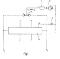
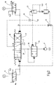
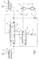
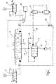
- Agencement de vanne- comprenant une vanne (10) réglable à plusieurs voies ayant un tiroir (12) de commande pour commander au moins un raccord (A, B) d'utilisateur, et- comprenant une ligne de commande LS, une vanne (20) logique, une vanne (22) supplémentaire et une balance (26) de pression,- dans lequel la différence entre deux pressions (xa, xb) de commande sert à commander le tiroir (12) de commande,- dans lequel les pressions (xa, xb) de commande commandent en outre la vanne (10) logique qui à son tour agit sur la vanne (22) supplémentaire et/ou commande la bascule (26) de pression,- dans lequel la bascule (26) de pression est montée en amont de la vanne (10) à plusieurs voies avec le tiroir (12) de commande entre une alimentation (P) en pression et un côté d'entrée de la vanne (10) à plusieurs voies et sur l'un de ses côtés d'entrée de commande est raccordé à une ligne (28) d'alimentation,- caractérisé en ce que la bascule (26) de pression communique avec la vanne (22) supplémentaire du côté de l'entrée de commande agissant en sens contraire de manière à ce que,- la bascule (26) de pression soit raccordée à un point (30) nodal, dans lequel débouche la ligne de commande LS, ainsi qu'un raccord pour du fluide de la vanne (22) supplémentaire sous la forme d'une vanne de limitation de la pression LS, la ligne de commande LS étant pourvue d'un étranglement ou d'un diaphragme (18), ou en ce que l'agencement de vanne a en outre un capteur (36) de pression et une électronique de vanne et,- en ce que la bascule (26) de pression communique par une ligne (41) de liaison avec la vanne (22) supplémentaire sous la forme d'une vanne de régulation de la pression LS, dans lequel, dans un conduit d'entrée supplémentaire allant de la ligne (28) d'alimentation à la ligne (40) de liaison, est inséré un diaphragme ou un étranglement (38) supplémentaire et la ligne de commande LS est raccordée à l'électronique de vanne par le capteur (36) de pression, et- et en ce que la vanne (20) logique est constituée en sélecteur agissant de manière inversée.
- Agencement de vanne suivant la revendication 1, caractérisée en ce que la vanne (22) supplémentaire peut être commandée au moyen d'un étage (24) de démultiplication de la pression, qui reçoit sa pression d'entrée par le côté de la sortie de la vanne (20) logique.
- Agencement de vanne suivant l'une des revendications précédentes, caractérisée en ce que la ligne LS est reliée à un microprocesseur (MC) de l'électronique de commande de vanne par le capteur (36) de pression.
- Agencement de vanne suivant l'une des revendications précédentes, caractérisée en ce que les pressions (xa, xb) de commande peuvent être prescrites par respectivement une vanne (14, 16) pilote agissant de manière séparée.
- Agencement de vanne suivant la revendication 3 et 4, caractérisée en ce que le microprocesseur (MC) de l'électronique de commande de vanne commande les deux vannes (14, 16) pilotes.
- Agencement de vanne suivant l'une des revendications précédentes, caractérisée en ce que la vanne (10) réglable à plusieurs voies comporte au moins un raccord (T) de cuve.
Applications Claiming Priority (2)
| Application Number | Priority Date | Filing Date | Title |
|---|---|---|---|
| DE200710014550 DE102007014550A1 (de) | 2007-03-27 | 2007-03-27 | Ventilanordnung |
| PCT/EP2008/000362 WO2008116515A1 (fr) | 2007-03-27 | 2008-01-18 | Ensemble vanne |
Publications (2)
| Publication Number | Publication Date |
|---|---|
| EP2126371A1 EP2126371A1 (fr) | 2009-12-02 |
| EP2126371B1 true EP2126371B1 (fr) | 2012-04-11 |
Family
ID=39316144
Family Applications (1)
| Application Number | Title | Priority Date | Filing Date |
|---|---|---|---|
| EP20080707119 Not-in-force EP2126371B1 (fr) | 2007-03-27 | 2008-01-18 | Ensemble vanne |
Country Status (4)
| Country | Link |
|---|---|
| US (1) | US8479636B2 (fr) |
| EP (1) | EP2126371B1 (fr) |
| DE (1) | DE102007014550A1 (fr) |
| WO (1) | WO2008116515A1 (fr) |
Families Citing this family (5)
| Publication number | Priority date | Publication date | Assignee | Title |
|---|---|---|---|---|
| EP2325390B2 (fr) * | 2009-10-20 | 2019-06-26 | Joseph Vögele AG | Poutre lisseuse et finisseuse de route |
| DE202011110161U1 (de) * | 2011-11-12 | 2013-02-08 | Knocks Fluid-Technik GmbH | Präzisionsvolumenstrombooster |
| DE102014005410A1 (de) * | 2014-03-01 | 2015-09-03 | Hydac Filtertechnik Gmbh | Ventilvorrichtung |
| KR102389687B1 (ko) * | 2015-01-14 | 2022-04-22 | 현대두산인프라코어 주식회사 | 건설기계의 제어 시스템 |
| US20170023149A1 (en) * | 2015-07-22 | 2017-01-26 | Cnh Industrial America Llc | Hydraulic signal control system and method |
Family Cites Families (16)
| Publication number | Priority date | Publication date | Assignee | Title |
|---|---|---|---|---|
| DE3428403A1 (de) * | 1983-08-01 | 1985-04-11 | Závody těžkého strojírenství Výzkumný ústav stavebních a zemních stroju, Brünn/Brno | Zweistufige, druckkompensierte hydraulische steuereinrichtung fuer mindestens zwei verbraucher |
| JPH076521B2 (ja) | 1987-06-30 | 1995-01-30 | 日立建機株式会社 | ロ−ドセンシング油圧駆動回路の制御装置 |
| DE68910940T2 (de) * | 1988-05-10 | 1994-04-21 | Hitachi Construction Machinery | Hydraulische antriebseinheit für baumaschinen. |
| WO1990000683A1 (fr) | 1988-07-08 | 1990-01-25 | Hitachi Construction Machinery Co., Ltd. | Appareil hydrodynamique |
| WO1990010795A1 (fr) | 1989-03-13 | 1990-09-20 | Hitachi Construction Machinery Co., Ltd. | Unite de commande hydraulique pour engin de terrassement |
| DE4036720C2 (de) * | 1990-11-17 | 2001-09-13 | Linde Ag | Steuerschaltung für die lastunabhängige Aufteilung eines Druckmittelstromes |
| DE9106442U1 (fr) | 1991-05-25 | 1991-08-14 | Buchholz Hydraulik Gmbh, 2300 Klausdorf, De | |
| DE4231399A1 (de) * | 1992-08-20 | 1994-02-24 | Rexroth Mannesmann Gmbh | Hydraulische Steuereinrichtung |
| DE4235709A1 (de) | 1992-10-22 | 1994-04-28 | Linde Ag | Hydrostatisches Antriebssystem |
| JP2972530B2 (ja) * | 1994-11-16 | 1999-11-08 | 新キャタピラー三菱株式会社 | 建設機械の作業機制御装置 |
| DE19615593B4 (de) * | 1996-04-19 | 2007-02-22 | Linde Ag | Hydrostatisches Antriebssystem |
| US6196247B1 (en) | 1996-11-11 | 2001-03-06 | Mannesmann Rexroth Ag | Valve assembly and method for actuation of such a valve assembly |
| EP1584823B1 (fr) | 2002-12-27 | 2010-07-14 | Hitachi Construction Machinery Co., Ltd. | Dispositif de commande d'un cylindre hydraulique de travail |
| DE102004005606B3 (de) * | 2004-02-05 | 2005-10-06 | Hydac Fluidtechnik Gmbh | Schaltungsanordnung |
| DE102005011395A1 (de) * | 2005-03-11 | 2006-09-14 | Bosch Rexroth Ag | Hydraulische Steueranordnung |
| DE102005050169A1 (de) | 2005-06-21 | 2006-12-28 | Bosch Rexroth Ag | LS-Steueranordnung und LS-Wegeventil |
-
2007
- 2007-03-27 DE DE200710014550 patent/DE102007014550A1/de not_active Withdrawn
-
2008
- 2008-01-18 US US12/449,929 patent/US8479636B2/en not_active Expired - Fee Related
- 2008-01-18 WO PCT/EP2008/000362 patent/WO2008116515A1/fr active Application Filing
- 2008-01-18 EP EP20080707119 patent/EP2126371B1/fr not_active Not-in-force
Also Published As
| Publication number | Publication date |
|---|---|
| US8479636B2 (en) | 2013-07-09 |
| DE102007014550A1 (de) | 2008-10-09 |
| WO2008116515A1 (fr) | 2008-10-02 |
| EP2126371A1 (fr) | 2009-12-02 |
| US20100018198A1 (en) | 2010-01-28 |
Similar Documents
| Publication | Publication Date | Title |
|---|---|---|
| DE102004050294B3 (de) | Hydraulische Ventilanordnung | |
| EP0760908A1 (fr) | Systeme de commande pour au moins deux consommateurs hydrauliques | |
| DE102012207422A1 (de) | Hydraulische Steueranordnung mit Lastdruckminderungund hydraulischer Ventilblock dafür | |
| EP0620371A1 (fr) | Système hydraulique pour alimentation de fonctions hydrauliques ouvertes ou fermées | |
| EP2126371B1 (fr) | Ensemble vanne | |
| DE102006002920A1 (de) | Hydraulische Steueranordnung | |
| WO2007096030A1 (fr) | Dispositif de commande hydraulique | |
| EP2636908A2 (fr) | Agencement de commande | |
| DE10219717B3 (de) | Hydraulische Ventilanordnung | |
| DE10343016B4 (de) | Hydraulisches Steuer- und Stellsystem mit Volumenausgleich | |
| EP2142808A1 (fr) | Ensemble de commande hydraulique | |
| EP1711715A1 (fr) | Systeme diaphragme de mesure d'un appareil hydraulique de division et d'addition de debit | |
| EP2171289A1 (fr) | Dispositif de commande pour au moins deux commandes hydrauliques | |
| EP1200743A1 (fr) | Dispositif de commande hydraulique destine a l'alimentation en agent de pression, reglee par detection de charge, de preference de plusieurs consommateurs hydrauliques | |
| DE102012208938A1 (de) | Closed-Center-Steuereinrichtung mit Konstant- und Verstellpumpe | |
| DE69937729T2 (de) | Ventil zum aufteilen des durchflusses | |
| DE2656032B2 (de) | Hydraulisches System mit mindestens zwei Verbrauchern | |
| EP1253327B1 (fr) | Circuit de commande hydraulique | |
| DE19709958A1 (de) | Hydrostatisches Antriebssystem | |
| DE10119276B4 (de) | Hydraulischer Steuerkreis | |
| DE3808866C2 (fr) | ||
| DE19603899A1 (de) | Hydraulische Steuervorrichtung zur Druckmittelversorgung mehrerer hydraulischer Verbraucher | |
| WO2016091528A1 (fr) | Agencement de soupapes hydraulique, bloc de soupapes hydraulique ayant un tel agencement de soupapes, et mécanisme d'entraînement hydraulique ayant un tel bloc de soupapes hydraulique | |
| EP2891805A2 (fr) | Système de commande et soupape de commande pour un tel système de commande | |
| EP2256350B1 (fr) | Dispositif d'amortissement hydraulique et système de réglage |
Legal Events
| Date | Code | Title | Description |
|---|---|---|---|
| PUAI | Public reference made under article 153(3) epc to a published international application that has entered the european phase |
Free format text: ORIGINAL CODE: 0009012 |
|
| 17P | Request for examination filed |
Effective date: 20090811 |
|
| AK | Designated contracting states |
Kind code of ref document: A1 Designated state(s): AT BE BG CH CY CZ DE DK EE ES FI FR GB GR HR HU IE IS IT LI LT LU LV MC MT NL NO PL PT RO SE SI SK TR |
|
| DAX | Request for extension of the european patent (deleted) | ||
| 17Q | First examination report despatched |
Effective date: 20101126 |
|
| GRAP | Despatch of communication of intention to grant a patent |
Free format text: ORIGINAL CODE: EPIDOSNIGR1 |
|
| GRAS | Grant fee paid |
Free format text: ORIGINAL CODE: EPIDOSNIGR3 |
|
| GRAA | (expected) grant |
Free format text: ORIGINAL CODE: 0009210 |
|
| AK | Designated contracting states |
Kind code of ref document: B1 Designated state(s): AT BE BG CH CY CZ DE DK EE ES FI FR GB GR HR HU IE IS IT LI LT LU LV MC MT NL NO PL PT RO SE SI SK TR |
|
| REG | Reference to a national code |
Ref country code: GB Ref legal event code: FG4D Free format text: NOT ENGLISH |
|
| REG | Reference to a national code |
Ref country code: CH Ref legal event code: EP Ref country code: CH Ref legal event code: NV Representative=s name: ISLER & PEDRAZZINI AG |
|
| REG | Reference to a national code |
Ref country code: AT Ref legal event code: REF Ref document number: 553300 Country of ref document: AT Kind code of ref document: T Effective date: 20120415 |
|
| REG | Reference to a national code |
Ref country code: IE Ref legal event code: FG4D Free format text: LANGUAGE OF EP DOCUMENT: GERMAN |
|
| REG | Reference to a national code |
Ref country code: DK Ref legal event code: T3 |
|
| REG | Reference to a national code |
Ref country code: DE Ref legal event code: R096 Ref document number: 502008006922 Country of ref document: DE Effective date: 20120606 |
|
| REG | Reference to a national code |
Ref country code: SE Ref legal event code: TRGR |
|
| REG | Reference to a national code |
Ref country code: NL Ref legal event code: VDEP Effective date: 20120411 |
|
| LTIE | Lt: invalidation of european patent or patent extension |
Effective date: 20120411 |
|
| PG25 | Lapsed in a contracting state [announced via postgrant information from national office to epo] |
Ref country code: CY Free format text: LAPSE BECAUSE OF FAILURE TO SUBMIT A TRANSLATION OF THE DESCRIPTION OR TO PAY THE FEE WITHIN THE PRESCRIBED TIME-LIMIT Effective date: 20120411 Ref country code: LT Free format text: LAPSE BECAUSE OF FAILURE TO SUBMIT A TRANSLATION OF THE DESCRIPTION OR TO PAY THE FEE WITHIN THE PRESCRIBED TIME-LIMIT Effective date: 20120411 Ref country code: IS Free format text: LAPSE BECAUSE OF FAILURE TO SUBMIT A TRANSLATION OF THE DESCRIPTION OR TO PAY THE FEE WITHIN THE PRESCRIBED TIME-LIMIT Effective date: 20120811 Ref country code: PL Free format text: LAPSE BECAUSE OF FAILURE TO SUBMIT A TRANSLATION OF THE DESCRIPTION OR TO PAY THE FEE WITHIN THE PRESCRIBED TIME-LIMIT Effective date: 20120411 Ref country code: NO Free format text: LAPSE BECAUSE OF FAILURE TO SUBMIT A TRANSLATION OF THE DESCRIPTION OR TO PAY THE FEE WITHIN THE PRESCRIBED TIME-LIMIT Effective date: 20120711 |
|
| PG25 | Lapsed in a contracting state [announced via postgrant information from national office to epo] |
Ref country code: GR Free format text: LAPSE BECAUSE OF FAILURE TO SUBMIT A TRANSLATION OF THE DESCRIPTION OR TO PAY THE FEE WITHIN THE PRESCRIBED TIME-LIMIT Effective date: 20120712 Ref country code: SI Free format text: LAPSE BECAUSE OF FAILURE TO SUBMIT A TRANSLATION OF THE DESCRIPTION OR TO PAY THE FEE WITHIN THE PRESCRIBED TIME-LIMIT Effective date: 20120411 Ref country code: PT Free format text: LAPSE BECAUSE OF FAILURE TO SUBMIT A TRANSLATION OF THE DESCRIPTION OR TO PAY THE FEE WITHIN THE PRESCRIBED TIME-LIMIT Effective date: 20120813 Ref country code: HR Free format text: LAPSE BECAUSE OF FAILURE TO SUBMIT A TRANSLATION OF THE DESCRIPTION OR TO PAY THE FEE WITHIN THE PRESCRIBED TIME-LIMIT Effective date: 20120411 Ref country code: LV Free format text: LAPSE BECAUSE OF FAILURE TO SUBMIT A TRANSLATION OF THE DESCRIPTION OR TO PAY THE FEE WITHIN THE PRESCRIBED TIME-LIMIT Effective date: 20120411 |
|
| PG25 | Lapsed in a contracting state [announced via postgrant information from national office to epo] |
Ref country code: RO Free format text: LAPSE BECAUSE OF FAILURE TO SUBMIT A TRANSLATION OF THE DESCRIPTION OR TO PAY THE FEE WITHIN THE PRESCRIBED TIME-LIMIT Effective date: 20120411 Ref country code: CZ Free format text: LAPSE BECAUSE OF FAILURE TO SUBMIT A TRANSLATION OF THE DESCRIPTION OR TO PAY THE FEE WITHIN THE PRESCRIBED TIME-LIMIT Effective date: 20120411 Ref country code: SK Free format text: LAPSE BECAUSE OF FAILURE TO SUBMIT A TRANSLATION OF THE DESCRIPTION OR TO PAY THE FEE WITHIN THE PRESCRIBED TIME-LIMIT Effective date: 20120411 Ref country code: NL Free format text: LAPSE BECAUSE OF FAILURE TO SUBMIT A TRANSLATION OF THE DESCRIPTION OR TO PAY THE FEE WITHIN THE PRESCRIBED TIME-LIMIT Effective date: 20120411 Ref country code: EE Free format text: LAPSE BECAUSE OF FAILURE TO SUBMIT A TRANSLATION OF THE DESCRIPTION OR TO PAY THE FEE WITHIN THE PRESCRIBED TIME-LIMIT Effective date: 20120411 |
|
| PLBE | No opposition filed within time limit |
Free format text: ORIGINAL CODE: 0009261 |
|
| STAA | Information on the status of an ep patent application or granted ep patent |
Free format text: STATUS: NO OPPOSITION FILED WITHIN TIME LIMIT |
|
| 26N | No opposition filed |
Effective date: 20130114 |
|
| PG25 | Lapsed in a contracting state [announced via postgrant information from national office to epo] |
Ref country code: ES Free format text: LAPSE BECAUSE OF FAILURE TO SUBMIT A TRANSLATION OF THE DESCRIPTION OR TO PAY THE FEE WITHIN THE PRESCRIBED TIME-LIMIT Effective date: 20120722 |
|
| PGFP | Annual fee paid to national office [announced via postgrant information from national office to epo] |
Ref country code: DK Payment date: 20130110 Year of fee payment: 6 |
|
| REG | Reference to a national code |
Ref country code: DE Ref legal event code: R097 Ref document number: 502008006922 Country of ref document: DE Effective date: 20130114 |
|
| BERE | Be: lapsed |
Owner name: HYDAC FLUIDTECHNIK G.M.B.H. Effective date: 20130131 |
|
| PG25 | Lapsed in a contracting state [announced via postgrant information from national office to epo] |
Ref country code: BG Free format text: LAPSE BECAUSE OF FAILURE TO SUBMIT A TRANSLATION OF THE DESCRIPTION OR TO PAY THE FEE WITHIN THE PRESCRIBED TIME-LIMIT Effective date: 20120711 |
|
| PG25 | Lapsed in a contracting state [announced via postgrant information from national office to epo] |
Ref country code: MC Free format text: LAPSE BECAUSE OF NON-PAYMENT OF DUE FEES Effective date: 20130131 |
|
| REG | Reference to a national code |
Ref country code: CH Ref legal event code: PL |
|
| GBPC | Gb: european patent ceased through non-payment of renewal fee |
Effective date: 20130118 |
|
| REG | Reference to a national code |
Ref country code: IE Ref legal event code: MM4A |
|
| REG | Reference to a national code |
Ref country code: FR Ref legal event code: ST Effective date: 20130930 |
|
| PG25 | Lapsed in a contracting state [announced via postgrant information from national office to epo] |
Ref country code: FI Free format text: LAPSE BECAUSE OF NON-PAYMENT OF DUE FEES Effective date: 20130118 Ref country code: BE Free format text: LAPSE BECAUSE OF NON-PAYMENT OF DUE FEES Effective date: 20130131 Ref country code: LI Free format text: LAPSE BECAUSE OF NON-PAYMENT OF DUE FEES Effective date: 20130131 Ref country code: CH Free format text: LAPSE BECAUSE OF NON-PAYMENT OF DUE FEES Effective date: 20130131 |
|
| PG25 | Lapsed in a contracting state [announced via postgrant information from national office to epo] |
Ref country code: FR Free format text: LAPSE BECAUSE OF NON-PAYMENT OF DUE FEES Effective date: 20130131 Ref country code: GB Free format text: LAPSE BECAUSE OF NON-PAYMENT OF DUE FEES Effective date: 20130118 |
|
| PG25 | Lapsed in a contracting state [announced via postgrant information from national office to epo] |
Ref country code: IE Free format text: LAPSE BECAUSE OF NON-PAYMENT OF DUE FEES Effective date: 20130118 |
|
| PGFP | Annual fee paid to national office [announced via postgrant information from national office to epo] |
Ref country code: SE Payment date: 20131126 Year of fee payment: 7 |
|
| REG | Reference to a national code |
Ref country code: AT Ref legal event code: MM01 Ref document number: 553300 Country of ref document: AT Kind code of ref document: T Effective date: 20130118 |
|
| PG25 | Lapsed in a contracting state [announced via postgrant information from national office to epo] |
Ref country code: AT Free format text: LAPSE BECAUSE OF NON-PAYMENT OF DUE FEES Effective date: 20130118 |
|
| PG25 | Lapsed in a contracting state [announced via postgrant information from national office to epo] |
Ref country code: MT Free format text: LAPSE BECAUSE OF FAILURE TO SUBMIT A TRANSLATION OF THE DESCRIPTION OR TO PAY THE FEE WITHIN THE PRESCRIBED TIME-LIMIT Effective date: 20120411 |
|
| REG | Reference to a national code |
Ref country code: DK Ref legal event code: EBP Effective date: 20140131 |
|
| PG25 | Lapsed in a contracting state [announced via postgrant information from national office to epo] |
Ref country code: DK Free format text: LAPSE BECAUSE OF NON-PAYMENT OF DUE FEES Effective date: 20140131 |
|
| PG25 | Lapsed in a contracting state [announced via postgrant information from national office to epo] |
Ref country code: TR Free format text: LAPSE BECAUSE OF FAILURE TO SUBMIT A TRANSLATION OF THE DESCRIPTION OR TO PAY THE FEE WITHIN THE PRESCRIBED TIME-LIMIT Effective date: 20120411 |
|
| PG25 | Lapsed in a contracting state [announced via postgrant information from national office to epo] |
Ref country code: HU Free format text: LAPSE BECAUSE OF FAILURE TO SUBMIT A TRANSLATION OF THE DESCRIPTION OR TO PAY THE FEE WITHIN THE PRESCRIBED TIME-LIMIT; INVALID AB INITIO Effective date: 20080118 Ref country code: LU Free format text: LAPSE BECAUSE OF NON-PAYMENT OF DUE FEES Effective date: 20130118 |
|
| REG | Reference to a national code |
Ref country code: SE Ref legal event code: EUG |
|
| PG25 | Lapsed in a contracting state [announced via postgrant information from national office to epo] |
Ref country code: SE Free format text: LAPSE BECAUSE OF NON-PAYMENT OF DUE FEES Effective date: 20150119 |
|
| PGFP | Annual fee paid to national office [announced via postgrant information from national office to epo] |
Ref country code: DE Payment date: 20160118 Year of fee payment: 9 |
|
| PG25 | Lapsed in a contracting state [announced via postgrant information from national office to epo] |
Ref country code: IT Free format text: LAPSE BECAUSE OF NON-PAYMENT OF DUE FEES Effective date: 20140118 |
|
| REG | Reference to a national code |
Ref country code: DE Ref legal event code: R119 Ref document number: 502008006922 Country of ref document: DE |
|
| PG25 | Lapsed in a contracting state [announced via postgrant information from national office to epo] |
Ref country code: DE Free format text: LAPSE BECAUSE OF NON-PAYMENT OF DUE FEES Effective date: 20170801 |