EP2126371B1 - Ventilanordnung - Google Patents
Ventilanordnung Download PDFInfo
- Publication number
- EP2126371B1 EP2126371B1 EP20080707119 EP08707119A EP2126371B1 EP 2126371 B1 EP2126371 B1 EP 2126371B1 EP 20080707119 EP20080707119 EP 20080707119 EP 08707119 A EP08707119 A EP 08707119A EP 2126371 B1 EP2126371 B1 EP 2126371B1
- Authority
- EP
- European Patent Office
- Prior art keywords
- valve
- control
- pressure
- additional
- line
- Prior art date
- Legal status (The legal status is an assumption and is not a legal conclusion. Google has not performed a legal analysis and makes no representation as to the accuracy of the status listed.)
- Not-in-force
Links
- 238000011144 upstream manufacturing Methods 0.000 claims abstract description 5
- 239000012530 fluid Substances 0.000 claims description 6
- 230000000694 effects Effects 0.000 claims description 2
- 230000001105 regulatory effect Effects 0.000 claims 1
- 238000010276 construction Methods 0.000 description 3
- 239000003921 oil Substances 0.000 description 3
- 238000009434 installation Methods 0.000 description 2
- 230000001419 dependent effect Effects 0.000 description 1
- 238000001514 detection method Methods 0.000 description 1
- 238000010586 diagram Methods 0.000 description 1
- 238000005516 engineering process Methods 0.000 description 1
- 239000010720 hydraulic oil Substances 0.000 description 1
- 238000005259 measurement Methods 0.000 description 1
- 230000007935 neutral effect Effects 0.000 description 1
- 238000005086 pumping Methods 0.000 description 1
Images
Classifications
-
- F—MECHANICAL ENGINEERING; LIGHTING; HEATING; WEAPONS; BLASTING
- F15—FLUID-PRESSURE ACTUATORS; HYDRAULICS OR PNEUMATICS IN GENERAL
- F15B—SYSTEMS ACTING BY MEANS OF FLUIDS IN GENERAL; FLUID-PRESSURE ACTUATORS, e.g. SERVOMOTORS; DETAILS OF FLUID-PRESSURE SYSTEMS, NOT OTHERWISE PROVIDED FOR
- F15B11/00—Servomotor systems without provision for follow-up action; Circuits therefor
- F15B11/02—Systems essentially incorporating special features for controlling the speed or actuating force of an output member
- F15B11/04—Systems essentially incorporating special features for controlling the speed or actuating force of an output member for controlling the speed
- F15B11/05—Systems essentially incorporating special features for controlling the speed or actuating force of an output member for controlling the speed specially adapted to maintain constant speed, e.g. pressure-compensated, load-responsive
-
- E—FIXED CONSTRUCTIONS
- E02—HYDRAULIC ENGINEERING; FOUNDATIONS; SOIL SHIFTING
- E02F—DREDGING; SOIL-SHIFTING
- E02F9/00—Component parts of dredgers or soil-shifting machines, not restricted to one of the kinds covered by groups E02F3/00 - E02F7/00
- E02F9/20—Drives; Control devices
- E02F9/22—Hydraulic or pneumatic drives
- E02F9/2278—Hydraulic circuits
- E02F9/2285—Pilot-operated systems
-
- F—MECHANICAL ENGINEERING; LIGHTING; HEATING; WEAPONS; BLASTING
- F15—FLUID-PRESSURE ACTUATORS; HYDRAULICS OR PNEUMATICS IN GENERAL
- F15B—SYSTEMS ACTING BY MEANS OF FLUIDS IN GENERAL; FLUID-PRESSURE ACTUATORS, e.g. SERVOMOTORS; DETAILS OF FLUID-PRESSURE SYSTEMS, NOT OTHERWISE PROVIDED FOR
- F15B11/00—Servomotor systems without provision for follow-up action; Circuits therefor
- F15B11/16—Servomotor systems without provision for follow-up action; Circuits therefor with two or more servomotors
- F15B11/161—Servomotor systems without provision for follow-up action; Circuits therefor with two or more servomotors with sensing of servomotor demand or load
- F15B11/163—Servomotor systems without provision for follow-up action; Circuits therefor with two or more servomotors with sensing of servomotor demand or load for sharing the pump output equally amongst users or groups of users, e.g. using anti-saturation, pressure compensation
-
- F—MECHANICAL ENGINEERING; LIGHTING; HEATING; WEAPONS; BLASTING
- F15—FLUID-PRESSURE ACTUATORS; HYDRAULICS OR PNEUMATICS IN GENERAL
- F15B—SYSTEMS ACTING BY MEANS OF FLUIDS IN GENERAL; FLUID-PRESSURE ACTUATORS, e.g. SERVOMOTORS; DETAILS OF FLUID-PRESSURE SYSTEMS, NOT OTHERWISE PROVIDED FOR
- F15B2211/00—Circuits for servomotor systems
- F15B2211/20—Fluid pressure source, e.g. accumulator or variable axial piston pump
- F15B2211/205—Systems with pumps
- F15B2211/2053—Type of pump
- F15B2211/20538—Type of pump constant capacity
-
- F—MECHANICAL ENGINEERING; LIGHTING; HEATING; WEAPONS; BLASTING
- F15—FLUID-PRESSURE ACTUATORS; HYDRAULICS OR PNEUMATICS IN GENERAL
- F15B—SYSTEMS ACTING BY MEANS OF FLUIDS IN GENERAL; FLUID-PRESSURE ACTUATORS, e.g. SERVOMOTORS; DETAILS OF FLUID-PRESSURE SYSTEMS, NOT OTHERWISE PROVIDED FOR
- F15B2211/00—Circuits for servomotor systems
- F15B2211/30—Directional control
- F15B2211/305—Directional control characterised by the type of valves
- F15B2211/30525—Directional control valves, e.g. 4/3-directional control valve
- F15B2211/3053—In combination with a pressure compensating valve
- F15B2211/30535—In combination with a pressure compensating valve the pressure compensating valve is arranged between pressure source and directional control valve
-
- F—MECHANICAL ENGINEERING; LIGHTING; HEATING; WEAPONS; BLASTING
- F15—FLUID-PRESSURE ACTUATORS; HYDRAULICS OR PNEUMATICS IN GENERAL
- F15B—SYSTEMS ACTING BY MEANS OF FLUIDS IN GENERAL; FLUID-PRESSURE ACTUATORS, e.g. SERVOMOTORS; DETAILS OF FLUID-PRESSURE SYSTEMS, NOT OTHERWISE PROVIDED FOR
- F15B2211/00—Circuits for servomotor systems
- F15B2211/30—Directional control
- F15B2211/32—Directional control characterised by the type of actuation
- F15B2211/329—Directional control characterised by the type of actuation actuated by fluid pressure
-
- F—MECHANICAL ENGINEERING; LIGHTING; HEATING; WEAPONS; BLASTING
- F15—FLUID-PRESSURE ACTUATORS; HYDRAULICS OR PNEUMATICS IN GENERAL
- F15B—SYSTEMS ACTING BY MEANS OF FLUIDS IN GENERAL; FLUID-PRESSURE ACTUATORS, e.g. SERVOMOTORS; DETAILS OF FLUID-PRESSURE SYSTEMS, NOT OTHERWISE PROVIDED FOR
- F15B2211/00—Circuits for servomotor systems
- F15B2211/40—Flow control
- F15B2211/405—Flow control characterised by the type of flow control means or valve
- F15B2211/40553—Flow control characterised by the type of flow control means or valve with pressure compensating valves
- F15B2211/40561—Flow control characterised by the type of flow control means or valve with pressure compensating valves the pressure compensating valve arranged upstream of the flow control means
-
- F—MECHANICAL ENGINEERING; LIGHTING; HEATING; WEAPONS; BLASTING
- F15—FLUID-PRESSURE ACTUATORS; HYDRAULICS OR PNEUMATICS IN GENERAL
- F15B—SYSTEMS ACTING BY MEANS OF FLUIDS IN GENERAL; FLUID-PRESSURE ACTUATORS, e.g. SERVOMOTORS; DETAILS OF FLUID-PRESSURE SYSTEMS, NOT OTHERWISE PROVIDED FOR
- F15B2211/00—Circuits for servomotor systems
- F15B2211/60—Circuit components or control therefor
- F15B2211/605—Load sensing circuits
- F15B2211/6051—Load sensing circuits having valve means between output member and the load sensing circuit
- F15B2211/6054—Load sensing circuits having valve means between output member and the load sensing circuit using shuttle valves
-
- F—MECHANICAL ENGINEERING; LIGHTING; HEATING; WEAPONS; BLASTING
- F15—FLUID-PRESSURE ACTUATORS; HYDRAULICS OR PNEUMATICS IN GENERAL
- F15B—SYSTEMS ACTING BY MEANS OF FLUIDS IN GENERAL; FLUID-PRESSURE ACTUATORS, e.g. SERVOMOTORS; DETAILS OF FLUID-PRESSURE SYSTEMS, NOT OTHERWISE PROVIDED FOR
- F15B2211/00—Circuits for servomotor systems
- F15B2211/60—Circuit components or control therefor
- F15B2211/605—Load sensing circuits
- F15B2211/6051—Load sensing circuits having valve means between output member and the load sensing circuit
- F15B2211/6055—Load sensing circuits having valve means between output member and the load sensing circuit using pressure relief valves
-
- F—MECHANICAL ENGINEERING; LIGHTING; HEATING; WEAPONS; BLASTING
- F15—FLUID-PRESSURE ACTUATORS; HYDRAULICS OR PNEUMATICS IN GENERAL
- F15B—SYSTEMS ACTING BY MEANS OF FLUIDS IN GENERAL; FLUID-PRESSURE ACTUATORS, e.g. SERVOMOTORS; DETAILS OF FLUID-PRESSURE SYSTEMS, NOT OTHERWISE PROVIDED FOR
- F15B2211/00—Circuits for servomotor systems
- F15B2211/60—Circuit components or control therefor
- F15B2211/63—Electronic controllers
- F15B2211/6303—Electronic controllers using input signals
- F15B2211/6306—Electronic controllers using input signals representing a pressure
- F15B2211/6313—Electronic controllers using input signals representing a pressure the pressure being a load pressure
-
- F—MECHANICAL ENGINEERING; LIGHTING; HEATING; WEAPONS; BLASTING
- F15—FLUID-PRESSURE ACTUATORS; HYDRAULICS OR PNEUMATICS IN GENERAL
- F15B—SYSTEMS ACTING BY MEANS OF FLUIDS IN GENERAL; FLUID-PRESSURE ACTUATORS, e.g. SERVOMOTORS; DETAILS OF FLUID-PRESSURE SYSTEMS, NOT OTHERWISE PROVIDED FOR
- F15B2211/00—Circuits for servomotor systems
- F15B2211/60—Circuit components or control therefor
- F15B2211/635—Circuits providing pilot pressure to pilot pressure-controlled fluid circuit elements
- F15B2211/6355—Circuits providing pilot pressure to pilot pressure-controlled fluid circuit elements having valve means
-
- Y—GENERAL TAGGING OF NEW TECHNOLOGICAL DEVELOPMENTS; GENERAL TAGGING OF CROSS-SECTIONAL TECHNOLOGIES SPANNING OVER SEVERAL SECTIONS OF THE IPC; TECHNICAL SUBJECTS COVERED BY FORMER USPC CROSS-REFERENCE ART COLLECTIONS [XRACs] AND DIGESTS
- Y10—TECHNICAL SUBJECTS COVERED BY FORMER USPC
- Y10T—TECHNICAL SUBJECTS COVERED BY FORMER US CLASSIFICATION
- Y10T137/00—Fluid handling
- Y10T137/8593—Systems
- Y10T137/87169—Supply and exhaust
- Y10T137/87177—With bypass
- Y10T137/87185—Controlled by supply or exhaust valve
Definitions
- the invention relates to a valve arrangement having an adjustable directional control valve with a control slide for driving at least one load connection and with a LS control line, wherein the differential pressure of two control pressures x a , x b is used to drive the control slide, wherein the control pressures additionally control a logic valve, which in turn acts on an additional valve and / or controls a pressure compensator, wherein the pressure compensator is connected upstream of the directional control valve with a control slide between a pressure supply and an input side of the directional control valve and connected on its one control input side to a pertinent supply line.
- valve arrangement is made US 5,134,853 A such as DE 689 10 940 T2 known.
- the known valve arrangement is part of a hydraulic drive unit for construction machines with a plurality of hydraulic actuators, which are operated by a pumped by the hydraulic pump hydraulic fluid.
- a first flow control valve for controlling the flow of hydraulic fluid supplied to a swing motor and a second flow control valve for controlling the flow of the hydraulic fluid supplied to a boom cylinder at predetermined pilot pressures are used.
- the discharge amount of the hydraulic pump for keeping constant the differential pressure between the pump discharge pressure and the maximum load pressure is controlled by a load detection control, so that the swinging motor and the boom cylinder obtains a delivery rate corresponding to the opening degree of the flow control valve.
- the pilot pressure for driving the oscillating motor associated first flow control valve is connected via a shuttle valve with a multi-way valve, whereby the multi-way valve is switched to another position and in this other position, the distribution cylinder associated with the distribution compensating valve with a control force such is that both hydraulic actuators are connected in parallel.
- Valve arrangements are increasingly being realized in the form of modular valve construction kits, which open up the possibility, in addition to the realization of standard variants, to record a certain number of special variants with.
- the pertinent special variants not only increase the design cost of construction for the variant itself, but also the volume of space available within the standard valve assembly for this purpose.
- a typical case with electrically controlled valves is the user's desire to be able to perform a pressure or independent switching function in addition to the control of the directional control valve.
- the function "quantity cutoff" is desired, in which, by limiting the pressure in the feedforward control of a section pressure balance, the standard cross section of the pressure compensator in the inflow to the gate valve of the directional control valve is closed.
- Solutions today are common in which such valves are offered with screws, by means of which the maximum inlet pressure to the two service connections (pipe connection) A or B or A and B can be set. The adjustment of the screws is done regularly by hand, which is associated with interruptions in work on the machine.
- a valve arrangement for controlling a consumer is known with a feed throttle acting as a continuously adjustable directional control valve, via which a pump connection with consumer connections A, B is connected, wherein the respective consumer is connected via working lines to the directional control valve and in each working line a throttle device is arranged over the drain volume flow of the hydraulic oil is adjustable by the consumer.
- the throttle device thus has in the known solution to two return throttles, which are each assigned to a user port A or B.
- Each pertinent return throttle is provided with a tank port T and there is a permanent connection between the return throttles and the respective assignable control pressures x a , x b , which act as a control pressure in the opposite direction to the spool with inlet orifice of the directional control valve.
- the pertinent way valve has so far no tank connection T.
- the respective return throttle is controlled via a total of two independent proportional magnets, which provide the said control pressures x a , x b available.
- the summarized in a valve block known valve assembly in turn is relatively large.
- a LS control arrangement with a directional control valve via its valve slide when set in one direction, a first consumer port A and setting in the other direction, a second consumer port B with a supply port P and the other consumer port to a drain port T are connectable, wherein via an inlet control edge, an opening cross-section of a Zulaufmeßblende is determined, which in turn is associated with an individual pressure compensator to keep the pressure drop across the Zulaufmeßblende, and with a LS Steuerölströmungspfad through which the load pressure downstream of Zulaufmeßblende tapped and through the valve spool into a LS control chamber of the Directional valve is signalable, wherein a maximum pressure in the LS control oil flow path can be limited via a pressure relief valve.
- the LS control oil flow path during adjustment of the valve spool in one direction successively or overlapping with two pressure limiting chambers is connected to each of which a pressure relief valve is assigned to the LS-pressure limitation, a multi-stage supply pressure limit is possible and the load pressure can be limited to different values in different Hub Ruthen the valve spool, which for certain tasks in mobile Working equipment is advantageous; stepless adjustment operations are not possible with the known solution.
- the invention is based on the object to further improve the known solutions to the effect that a continuous adjustment of the valve assembly is possible and that this requires little installation space.
- a related object solves a valve assembly with the features of claim 1 in its entirety.
- a valve arrangement according to the invention is characterized in that the pressure compensator on the counter-acting control input side is connected to the additional valve such that it is connected to a junction in which the LS control line opens and a fluid connection for the Additional valve in the form of a LS pressure relief valve, wherein the LS control line is provided with a throttle or a diaphragm (variant 1), or that it is connected via a connecting line to the additional valve in the form of a LS pressure control valve, wherein in an additional supply line of the supply line to the connecting line an additional orifice or throttle is inserted and the LS control line is connected via a pressure sensor to a valve electronics (variant 2), and that the logic valve is designed as an inverted acting shuttle valve.
- control pressures x a , x b additionally control a logic valve, which in turn acts on an additional valve and / or controls a pressure compensator, which is connected upstream of the directional control valve with spool, the difference of the two control pressures x a , x b moves first the Spool of the directional control valve, wherein the lower of the two control pressures x a , x b either the further valve activates in the form of the additional valve and / or acting on the pressure compensator.
- the two proportional solenoids which are preferably provided for providing the actuation pressures x a , x b , are operated simultaneously, wherein the selection of the higher or lower pilot pressure as actuation pressure x a , x b is effected by a logic valve which is embodied according to the invention in the manner of an inverted shuttle valve.
- the additional valve is an LS pressure limiting valve LS-DBV in the valve section. Since the control of a high-pressure pressure relief valve is carried out with low pressure, preferably a pressure booster stage is interposed.
- a valve arrangement with an adjustable directional control valve 10 with a control slide 12 (FIG. Fig.2 ff) for driving two consumer connections A, B.
- the structure of such adjustable directional control valves 10 with spool 12 is in the prior art ( EP 0 935 713 B1 . DE 10 2005 050 169 A1 ) is well known, so that will not be discussed here at this point.
- the directional control valve 10 is further connected to a pressure supply source P, for example in the form of a constant pressure pump, which withdraws from a reservoir, for example in the form of a tank, hydraulic medium, which flows back through a tank port T after passing through the hydraulic circuit back into said reservoir.
- a pressure supply source P for example in the form of a constant pressure pump, which withdraws from a reservoir, for example in the form of a tank, hydraulic medium, which flows back through a tank port T after passing through the hydraulic circuit back into said reservoir.
- the directional control valve 10 has a tank connection T that is provided.
- the directional control valve 10 has an LS control line, which is shown in the figures with LS.
- the differential pressure of two control pressures x a , x b is provided, in the usual and therefore unspecified manner via two pilot valves 14,16 are given.
- the pilot valves 14,16 are in the Fig. 2ff shown, wherein the connection ST the control pressure (usually 20 to 40 bar) referred to in the control oil circuit, which serves in particular the supply of unspecified low-pressure consumer.
- the LS control line is according to Fig.1 to 3 provided with a throttle or aperture 18.
- the two driving pressures x a , x b not only in the opposite direction to the spool 12 of the directional control valve 10, but are also connected in opposite direction of action to a logic valve 20, which acts as a shuttle valve and according to the present embodiments as inverted Shuttle valve is formed.
- the control pressure acting on the spool 12 x a allows the fluid-conducting connection between the terminals P and A and the control pressure x b acts on the spool 12 in the opening direction of the ports P and B to be interconnected.
- the spool 12 assumes its spring-centered position, as in the Fig.2ff represented, which is also referred to the neutral position of the directional control valve 10.
- an additional valve 22 is connected, which is designed as a pressure relief valve DBV.
- a pressure booster stage 24 Prior to the pressure relief valve DBV the input side, a pressure booster stage 24 is connected, which makes it possible to bring the input pressure from the output side of the logic valve 20 to a higher pressure relative to the input side of the additional valve 22. In this way, in order to obtain improved drive efficiency, it is possible to use the lower pilot pressure x a or x b for driving the additional valve 22.
- the basic circuit after the Fig.1 In principle, it is possible to carry out the "quantity cut" described in the introduction in a stepless manner and / or to achieve a perceptible contact pressure control for a working equipment, connected to the user or consumer connections A, B.
- the additional valve 22 is designed as a so-called.
- LS-pressure relief valve (LS-DBV) and is fed by the LS-pressure of the LS control line and controls, as stated, so far the the control spool 12 of the directional control valve 10 upstream section pressure compensator 26 at ,
- the LS-DBV is driven by the lower of the two driving pressures x a , x b on its spring side, again selecting the driving pressures x a , x b by the inverted shuttle valve as a logic valve 20. Since usually the spool 12 is deflected with a lower control pressure x a , x b , this low pressure must also control the high-pressure LS-DBV as an additional valve 22.
- the pressure booster stage 24 which is connected between control pressure and so-called spring chamber of the LS-DBV, wherein the pressure booster piston (not shown) is designed such that it rests with its large area at the control pressure and the small area abuts against the spring chamber of the LS-DBV.
- the electrically adjustable Mengenabschneidung is possible in an advantageous manner.
- the valve assembly according to the Figure 3 for the section pressure compensator 26 a tank connection T on.
- the pertinent T-port of the pressure compensator 26 can only be opened when the pressure compensator piston 32 has already almost closed the supply channel P (supply line 28) or just closed or already closed when moving against the control spring 34. This can not only a pressure relief in the inlet to the respective pipe connection (user port A, B) can be achieved, but also a pressure control.
- variable 2 eliminates the node 30 with throttle or fixed orifice 18 and the LS control line is connected via a pressure sensor 36 to a microprocessor or microcontroller MC a valve electronics not shown.
- the control input sides are the pressure compensator 26 connected to the supply line 28, wherein in one of the supply lines, an additional aperture or throttle 38 is inserted.
- the said supply line opens into a connecting line 40 between the additional valve 22 and a drive side of the pressure compensator 26.
- the further valve is designed as an additional valve 22 in the form of a so-called.
- LS pressure control valve which is not the LS pressure in the LS Control line, but is fed by the pressure of the pressure supply source P and thus generates an artificial load pressure in the spring chamber of the section pressure compensator 26, which can be varied from zero to Pmax. Regardless of the actual load pressure, the pressure difference can thus be adjusted almost arbitrarily by electrical means. In this way, an extreme fine control at low pressure difference and maximum pumping amount via the section at maximum pressure difference is possible.
- the measurement of the load pressure is carried out via a pressure sensor 36, which forwards the pressure value to a microprocessor or microcontroller MC as part of an unspecified valve electronics.
- the valve electronics then control the low control pressure after specification of an external setpoint and simultaneously corrects the higher control pressure by the zero-point correction of the lower control pressure.
- a further advantageous application of the pertinent solution is to provide a control block not shown in detail of a specific nominal diameter, in which only a single consumer connection (user port A, B) requires a larger nominal diameter. Then, for cost-saving reasons, the smaller control block can be maintained, because the necessary large amount can be achieved via a high pressure difference across the metering orifice formed by the inlet side of the valve spool 12 (input of the supply line 28).
Landscapes
- Engineering & Computer Science (AREA)
- General Engineering & Computer Science (AREA)
- Physics & Mathematics (AREA)
- Fluid Mechanics (AREA)
- Mechanical Engineering (AREA)
- Mining & Mineral Resources (AREA)
- Civil Engineering (AREA)
- Structural Engineering (AREA)
- Fluid-Pressure Circuits (AREA)
Abstract
Description
- Die Erfindung betrifft eine Ventilanordnung mit einem einstellbaren Wegeventil mit einem Steuerschieber zum Ansteuern mindestens eines Verbraucheranschlusses und mit einer LS-Steuerleitung, wobei zum Ansteuern des Steuerschiebers der Differenzdruck zweier Ansteuerdrücke xa, xb dient, wobei die Ansteuerdrücke zusätzlich ein Logikventil ansteuern, das wiederum auf ein Zusatzventil einwirkt und/oder eine Druckwaage ansteuert, wobei die Druckwaage dem Wegeventil mit Steuerschieber zwischen einer Druckversorgung und einer Eingangsseite des Wegeventils vorgeschaltet und auf ihrer einen Steuereingangsseite an eine dahingehende Versorgungsleitung angeschlossen ist.
- Eine derartige Ventilanordnung ist aus
US 5,134,853 A sowieDE 689 10 940 T2 bekannt. Die bekannte Ventilanordnung ist Teil einer hydraulischen Antriebseinheit für Baumaschinen mit mehreren Hydraulikstellgliedern, die durch eine von der Hydraulikpumpe geförderte Hydraulikflüssigkeit betrieben werden. Beispielsweise wird ein erstes Durchflussregelventil zum Regeln des einem Schwingmotor zugeführten Stroms der Hydraulikflüssigkeit und ein zweites Durchflussregelventil zum Regeln des einem Auslegerzylinder zugeführten Stroms der Hydraulikflüssigkeit mit bestimmten Vorsteuerdrücken eingesetzt. - Im Betrieb wird die Ausströmmenge der Hydraulikpumpe zum Konstanthalten des Differenzdrucks zwischen dem Pumpenauslassdruck und dem Höchstlastdruck von einer Lasterfassungsregelung geregelt, so dass der Schwingmotor und der Auslegerzylinder eine Förderleistung erhält, welche dem Öffnungsgrad des Durchflussregelventils entspricht. Im kombinierten Betrieb von Schwenkkörper und Auslegerzylinder wird der Vorsteuerdruck zum Antrieb des dem Schwingmotor zugeordneten ersten Durchflussregelventils über ein Wechselventil mit einem Mehrwegehahn verbunden, wodurch der Mehrwegehahn in eine andere Stellung geschaltet wird und in dieser anderen Stellung das dem Auslegerzylinder zugeordnete Verteilungsausgleichsventil mit einer Steuerkraft derart beaufschlagt wird, dass beide Hydraulikstellglieder parallel geschaltet werden.
- Ventilanordnungen werden zusehends in der Art von modular aufbauenden Ventilbaukästen realisiert, die die Möglichkeit eröffnen, neben der Realisierung von Standardvarianten eine gewisse Anzahl von Sondervarianten mit zu erfassen. In der Regel erhöhen dabei die dahingehenden Sondervarianten nicht nur den konstruktiven Bauaufwand für die Variante selbst, sondern auch das dafür bereitzuhaltende Einbauvolumen innerhalb der Standardventilbaugruppe.
- Ein typischer Fall bei elektrisch gesteuerten Ventilen ist der Anwenderwunsch, außer der Steuerung des Wegeventils auch noch eine Druck- oder unabhängige Schaltfunktion ausführen zu können. Gewünscht ist beispielsweise die Funktion "Mengenabschneidung", bei der durch eine Druckbegrenzung in der Vorsteuerung einer Sektionsdruckwaage der Regelquerschnitt der Druckwaage im Zufluß zur Schieberblende des Wegeventils geschlossen wird. Dabei sind heute Lösungen üblich, bei denen solche Ventile mit Stellschrauben angeboten werden, mittels deren man den maximalen Zulaufdruck zu den beiden Nutzanschlüssen (Rohranschluß) A oder B oder A und B einstellen kann. Das Einstellen der Stellschrauben geschieht regelmäßig von Hand, was mit Arbeitsunterbrechungen an der Maschine einhergeht.
- Eine elektrische Einstellung durch Einstellung eines Potentiometers wäre somit bereits eine wünschenswerte Verbesserung, wobei dahingehend im Stand der Technik mobile Wegeventilbaureihen bekannt sind, die zur Realisierung einer solchen elektrischen Einstellfunktion aber einen dritten Proportionalmagneten benötigen, der wiederum viel Einbauraum an der jeweiligen Arbeitsmaschine einnimmt. Ferner kommt hierbei ein zusätzlicher Verdrahtungsaufwand für die Realisierung der benötigten Bustechnik mit hinzu.
- Durch die
EP 0 935 713 B1 ist eine Ventilanordnung zur Ansteuerung eines Verbrauchers bekannt mit einem als Zulaufdrossel wirkenden, stetig einstellbaren Wegeventil, über das ein Pumpenanschluß mit Verbraucheranschlüssen A, B verbindbar ist, wobei der jeweilige Verbraucher über Arbeitsleitungen an das Wegeventil angeschlossen und in jeder Arbeitsleitung eine Drosseleinrichtung angeordnet ist, über die der Ablaufvolumenstrom des Hydrauliköls vom Verbraucher einstellbar ist. Dadurch, dass bei der bekannten Lösung jeweils eine Steuerseite der Drosseleinrichtungen und eine Steuerseite des Wegeventils über einen Steuerkanal mit jeweils einer Steuereinheit verbunden sind, wobei mittels der beiden Steuereinheiten die Steuerdrücke in den beiden Steuerkanälen derart unabhängig voneinander einstellbar sind, dass beim Einstellen des Zulaufvolumenstroms beide Steuerdrücke größer als Null sind und die ablaufseitige Drosseleinrichtung unabhängig von einer Ventilschieberstellung des Wegeventils vollständig aufsteuerbar ist, ist eine Ventilanordnung geschaffen, bei der mit minimiertem vorrichtungstechnischen Aufwand die Energieverluste im Ablauf von einem Verbraucher auf ein Minimum reduzierbar sind. Der Hydraulikvolumenstrom wird dabei über ein als Zulaufdrossel wirkendes Wegeventil eingestellt. - Die Drosseleinrichtung weist mithin bei der bekannten Lösung zwei Rücklaufdrosseln auf, die jeweils einem Nutzanschluß A oder B zugeordnet sind. Jede dahingehende Rücklaufdrossel ist mit einem Tankanschluß T versehen und es besteht eine permanente Verbindung zwischen den Rücklaufdrosseln und den jeweils zuordenbaren Ansteuerdrücken xa, xb, die insoweit als Ansteuerdruck in gegenläufiger Richtung auf den Steuerschieber mit Zulaufblende des Wegeventils einwirken. Das dahingehende Wegeventil weist insoweit keinen Tankanschluß T auf. Somit wird bei der bekannten Lösung neben dem Steuerschieber des Wegeventils auch die jeweilige Rücklaufdrossel über insgesamt zwei voneinander unabhängige Proportiorialmagnete gesteuert, die die genannten Steuerdrücke xa, xb zur Verfügung stellen. Die in einen Ventilblock zusammengefaßte bekannte Ventilanordnung baut wiederum relativ groß auf.
- Durch die
DE 10 2005 050 169 A1 ist eine LS-Steueranordnung mit einem Wegeventil bekannt, über dessen Ventilschieber bei Einstellen in eine Richtung ein erster Verbraucheranschluß A und bei Einstellen in der anderen Richtung ein zweiter Verbraucheranschluß B mit einem Zulaufanschluß P und der jeweils andere Verbraucheranschluß mit einem Ablaufanschluß T verbindbar sind, wobei über eine Zulaufsteuerkante ein Öffnungsquerschnitt einer Zulaufmeßblende bestimmt ist, der wiederum eine Individualdruckwaage zum Konstanthalten des Druckabfalls über die Zulaufmeßblende zugeordnet ist, und mit einem LS-Steuerölströmungspfad, über den der Lastdruck stromabwärts der Zulaufmeßblende abgreifbar und durch den Ventilschieber hindurch in eine LS-Steuerkammer des Wegeventils meldbar ist, wobei ein Maximaldruck in dem LS-Steuerölströmungspfad über ein Druckbegrenzungsventil begrenzbar ist. Dadurch, dass bei der bekannten Lösung der LS-Steuerölströmungspfad während der Einstellung des Ventilschiebers in der einen Richtung nacheinander oder überlappend mit zwei Druckbegrenzungskammern verbindbar ist, denen jeweils ein Druckbegrenzungsventil zur LS-Druckbegrenzung zugeordnet ist, ist eine mehrstufige Zulaufdruckbegrenzung möglich und der Lastdruck läßt sich in unterschiedlichen Hubbereichen des Ventilschiebers auf verschiedene Werte begrenzen, was für bestimmte Aufgabenstellungen bei mobilen Arbeitsgeräten vorteilhaft ist; stufenlose Einstellvorgänge sind jedoch mit der bekannten Lösung nicht möglich. - Ausgehend von diesem Stand der Technik liegt daher der Erfindung die Aufgabe zugrunde, die bekannten Lösungen dahingehend weiter zu verbessern, dass eine stufenlose Einstellung der Ventilanordnung möglich ist und dass diese wenig Einbauraum benötigt. Eine dahingehende Aufgabe löst eine Ventilanordnung mit den Merkmalen des Patentanspruches 1 in seiner Gesamtheit.
- Gemäß dem kennzeichnenden Teil des Patentanspruchs 1 zeichnet sich eine erfindungsgemäße Ventilanordnung dadurch aus, dass die Druckwaage auf der gegenläufig wirkenden Steuereingangsseite mit dem Zusatzventil derart verbunden ist, dass diese an eine Knotenstelle angeschlossen ist, in die die LS-Steuerleitung mündet sowie ein Fluidanschluss für das Zusatzventil in Form eines LS-Druckbegrenzungsventils, wobei die LS-Steuerleitung mit einer Drossel oder einer Blende versehen ist (Variante 1), oder dass diese über eine Verbindungsleitung mit dem Zusatzventil in Form eines LS-Druckregelventils verbunden ist, wobei in eine zusätzliche Zuführleitung von der Versorgungsleitung zur Verbindungsleitung eine zusätzliche Blende oder Drossel eingesetzt ist und die LS-Steuerleitung über einen Drucksensor an eine Ventilelektronik angeschlossen ist (Variante 2), und dass das Logikventil als invertiert wirkendes Wechselventil ausgebildet ist. Dadurch, dass die Ansteuerdrücke xa, xb zusätzlich ein Logikventil ansteuern, das wiederum auf ein Zusatzventil einwirkt und/oder eine Druckwaage ansteuert, die vor dem Wegeventil mit Steuerschieber vorgeschaltet ist, bewegt die Differenz der beiden Ansteuerdrücke xa, xb zunächst den Steuerschieber des Wegeventils, wobei der niedrigere der beiden Ansteuerdrücke xa, xb entweder das weitere Ventil ansteuert in Form des Zusatzventils und/oder auf die Druckwaage einwirkt. Die vorzugsweise zur Bereitstellung der Ansteuerdrücke xa, xb vorgesehenen beiden Proportionalmagnete werden gleichzeitig betrieben, wobei die Auswahl des höheren oder niedrigeren Pilotdrucks als Ansteuerdruck xa, xb durch ein Logikventil erfolgt, das erfindungsgemäß in der Art eines invertierten Wechselventils ausgebildet ist.
- Bei einer ersten Variante der erfindungsgemäßen Ventilanordnung ist das Zusatzventil ein LS-Druckbegrenzungsventil LS-DBV in der Ventilsektion. Da die Ansteuerung eines Hochdruck-Druckbegrenzungsventils mit Niederdruck erfolgt, ist vorzugsweise eine Druckübersetzungsstufe zwischengeschaltet.
- Mit der erfindungsgemäßen Lösung läßt sich Bauraum sparen und mit nur wenigen funktionssicheren Komponenten die sog. "Mengenabschneidung" elektrisch vornehmen und einstellen. Eine weitere Anwendungsmöglichkeit besteht in der sog. Auflagedruckregelung, bei der die Auflagekraft eines Arbeitsgerätes reduziert werden kann, was beispielsweise eine Rolle spielt bei Mähbalken von Böschungsmähern, Haspelführungen von Mähdreschern sowie sog. Packern an Traktoren etc..
- Weitere vorteilhafte Ausführungsformen sind Gegenstand der sonstigen Unteransprüche.
- Im folgenden wird die erfindungsgemäße Ventilanordnung anhand verschiedener Ausführungsbeispiele nach der Zeichnung näher erläutert. Dabei zeigen in prinzipieller Darstellung in der Art von Schaltplänen die
- Fig.1 bis 4
- vier voneinander verschiedene Ausführungsformen der erfindungsgemäßen Ventilanordnung, wobei die
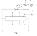
Fig.1 den prinzipiellen grundsätzlichen Aufbau der Ventilanordnung betrifft. - So zeigt die
Fig.1 eine Ventilanordnung mit einem einstellbaren Wegeventil 10 mit einem Steuerschieber 12 (Fig.2 ff) zum Ansteuern zweier Verbraucheranschlüsse A,B. Der Aufbau dahingehender einstellbarer Wegeventile 10 mit Steuerschieber 12 ist im Stand der Technik (EP 0 935 713 B1 ,DE 10 2005 050 169 A1 ) hinlänglich bekannt, so dass an dieser Stelle hierauf nicht mehr näher eingegangen wird. Das Wegeventil 10 ist ferner an eine Druckversorgungsquelle P, beispielsweise in Form einer Konstantdruckpumpe angeschlossen, die aus einem Reservoir, beispielsweise in Form eines Tanks, Hydraulikmedium entnimmt, das über einen Tankanschluß T nach Durchlaufen des hydraulischen Kreises wieder in das genannte Reservoir zurückfließt. Bei den vorliegenden Ausführungsbeispielen der erfindungsgemäßen Ventilanordnung liegt unter anderem eine Besonderheit darin, dass das Wegeventil 10 über einen dahingehenden Tankanschluß T verfügt. - Weiterhin verfügt das Wegeventil 10 über eine LS-Steuerleitung, die in den Figuren mit LS wiedergegeben ist. Zum Ansteuern des Steuerschiebers 12 ist der Differenzdruck zweier Ansteuerdrücke xa, xb vorgesehen, die in üblicher und daher nicht näher beschriebener Weise über zwei Pilotventile 14,16 vorgegeben sind. Die Pilotventile 14,16 sind in den
Fig. 2ff dargestellt, wobei der Anschluß ST den Steuerdruck (üblich sind 20 bis 40 bar) im Steuerölkreis bezeichnet, der insbesondere der Versorgung der nicht näher bezeichneten Niederdruckverbraucher dient. Ferner ist die LS-Steuerleitung gemäß denFig.1 bis 3 mit einer Drossel oder Blende 18 versehen. - Wie die
Fig.1 des weiteren zeigt, wirken die beiden Ansteuerdrücke xa, xb nicht nur in entgegengesetzter Richtung auf den Steuerschieber 12 des Wegeventils 10 ein, sondern sind auch in gegenläufiger Wirkrichtung an ein Logikventil 20 angeschlossen, das als Wechselventil und gemäß den vorliegenden Ausführungen als invertiert wirkendes Wechselventil ausgebildet ist. Der am Steuerschieber 12 wirkende Ansteuerdruck xa ermöglicht die fluidführende Verbindung zwischen den Anschlüssen P und A und der Ansteuerdruck xb wirkt am Steuerschieber 12 in Öffnungsrichtung der miteinander zu verbindenden Anschlüsse P und B. Wirkt kein Ansteuerdruck xa, xb oder heben sich die Ansteuerdrücke xa, xb von ihrem Differenzdruck her gegenseitig auf, nimmt der Steuerschieber 12 seine federzentrierte Mittenstellung ein, wie in denFig.2ff dargestellt, die man auch mit der Neutralstellung des Wegeventils 10 bezeichnet. - An das Logikventil ist ein weiteres Ventil in Form eines Zusatzventils 22 angeschlossen, das als Druckbegrenzungsventil DBV ausgebildet ist. Vor das Druckbegrenzungsventil DBV ist eingangsseitig eine Druckübersetzungsstufe 24 geschaltet, die es ermöglicht, den Eingangsdruck von der Ausgangsseite des Logikventils 20 auf einen höheren Druck bezogen auf die Eingangsseite des Zusatzventils 22 zu bringen. Dergestalt ist es für den Erhalt einer verbesserten Effizienz der Ansteuerung möglich, den niedrigeren Pilotdruck xa oder xb zur Ansteuerung des Zusatzventils 22 einzusetzen. Mit der Grundschaltung nach der
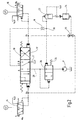
Fig.1 ist es prinzipiell möglich, in stufenloser Weise die eingangs beschriebene "Mengenabschneidung" durchzuführen und/oder eine sinnfällige Auflagedruckregelung für eine Arbeitsgerätschaft, angeschlosen an die Nutzer- oder Verbraucheranschlüsse A, B, zu erreichen. Erfindungsgemäß ist jedoch vorgesehen, neben dem Logikventil 20 und dem Zusatzventil 22 gemäß der Darstellung nach derFig.2 auf der Pumpeneingangsseite des Wegeventils 10 zwischen der Druckversorgungsquelle P und dem dahingehenden Eingang des Wegeventils 10 eine Druckwaage 26 zu schalten, die auf ihrer einen Steuereingangsseite an die dahingehende Versorgungsleitung 28 angeschlossen ist und auf der gegenläufig wirkenden Steuereingangsseite ist diese gemäß der ersten Ausführungsform (Variante 1) an eine Knotenstelle 30 angeschlossen, in die die LS-Steuerleitung mündet sowie ein Fluidanschluß für das Zusatzventil 22 in Form eines Druckbegrenzungsventils mit angeschlossener Druckübersetzungsstufe 24. Gemäß der Schaltplandarstellung nach derFig.2 ist mit der dahingehenden Ventilanordnung eine elektrisch ansteuerbare "Mengenabschneidung" mit zwei gleichzeitig betriebenen proportionalen Pilotventilen 14,16 erreicht. - Im vorliegenden Ausführungsbeispiel ist das Zusatzventil 22 als sog. LS-Druckbegrenzungsventil (LS-DBV) ausgebildet und wird vom LS-Druck der LS-Steuerleitung gespeist und steuert, wie dargelegt, insoweit die dem Steuerschieber 12 des Wegeventils 10 vorgeschaltete Sektions-Druckwaage 26 an. Das LS-DBV wird vom niedrigeren der beiden Ansteuerdrücke xa, xb auf seiner Federseite angesteuert, wobei wiederum die Auswahl der Ansteuerdrücke xa, xb durch das invertierte Wechselventil als Logikventil 20 erfolgt. Da üblicherweise der Steuerschieber 12 mit einem niedrigeren Ansteuerdruck xa, xb ausgelenkt wird, muß dieser niedrige Druck auch das Hochdruck-LS-DBV als Zusatzventil 22 steuern. Hierzu dient die Druckübersetzungsstufe 24, die zwischen Ansteuerdruck und sog. Federkammer des LS-DBV geschaltet ist, wobei der Druckübersetzerkolben (nicht dargestellt) derart ausgelegt ist, dass er mit seiner großen Fläche am Ansteuerdruck anliegt und die kleine Fläche an der Federkammer des LS-DBV anliegt. Mit dem dahingehenden Aufbau ist die elektrisch einstellbare Mengenabschneidung in vorteilhafter Weise möglich.
- Die nachfolgenden Ausführungsbeispielen werden nur noch insofern erläutert, als sie sich wesentlich von den vorangegangenen Ausführungsbeispielen unterscheiden. Dabei werden für dieselben Komponenten der Ventilanordnung dieselben Bezugszeichen eingesetzt und die bisher getroffenen Ausführungen gelten auch insoweit für die noch vorzustellenden Ausführungsbeispiele nach den
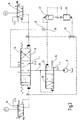
Fig. 3 und4 . - Für eine Auflagedruckregelung weist die Ventilanordnung nach der
Fig.3 für die Sektions-Druckwaage 26 einen Tankanschluß T auf. Der dahingehende T-Anschluß der Druckwaage 26 kann erst dann geöffnet werden, wenn der Druckwaagenkolben 32 bei Bewegung gegen die Regelfeder 34 zuerst den Versorgungskanal P (Versorgungsleitung 28) schon fast geschlossen hat oder gerade schließt oder bereits geschlossen hat. Damit kann nicht nur eine Druckbegrenzung im Zulauf zum jeweiligen Rohranschluß (Nutzanschluß A, B) erreicht werden, sondern auch eine Druckregelung. Dergestalt kann dann die Auflagekraft eines nicht näher dargestellten Arbeitsgerätes einer Arbeitsmaschine auf den Boden reduziert werden, indem bei geöffnetem Steuerschieber 12 die Sektions-Druckwaage 26 einerseits einen Volumenstrom zum jeweiligen Nutzanschluß A, B aber auch vom jeweiligen Nutzanschluß A, B zum Tankanschluß T steuern kann. Mit der Ausführungsform nach derFig.3 ist also eine elektrisch ansteuerbare Mengenabschneidung mit Auflagedruckregelung möglich. - Bei der zweiten Ausführungsform nach der
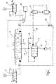
Fig.4 (Variante 2) entfällt die Knotenstelle 30 mit Drossel- oder Festblende 18 und die LS-Steuerleitung ist über einen Drucksensor 36 an einen Microprozessor oder Microcontroller MC einer nicht näher dargestellten Ventilelektronik angeschlossen. Jedoch sind die Steuereingangsseiten der Druckwaage 26 an die Versorgungsleitung 28 angeschlossen, wobei in einer der Zuführleitungen eine zusätzliche Blende oder Drossel 38 eingesetzt ist. Über diese Drossel 38 mündet die genannte Zuführleitung in eine Verbindungsleitung 40 zwischen Zusatzventil 22 und einer Ansteuerseite der Druckwaage 26. Demgemäß ist das weitere Ventil als Zusatzventil 22 in Form eines sog. LS-Druckregelventils ausgebildet, das nicht vom LS-Druck in der LS-Steuerleitung, sondern vom Druck der Druckversorgungsquelle P gespeist wird und dergestalt im Federraum der Sektions-Druckwaage 26 einen künstlichen Lastdruck erzeugt, der vom Wert Null bis Pmax variiert werden kann. Unabhängig vom tatsächlichen Lastdruck kann damit auf elektrischem Wege die Druckdifferenz fast beliebig eingestellt werden. Dergestalt ist eine extreme Feinsteuerung bei niedriger Druckdifferenz und maximaler Pumpenmenge über die Sektion bei maximaler Druckdifferenz möglich. Die Messung des Lastdruckes erfolgt dabei über einen Drucksensor 36, der den Druckwert an einen Microprozessor oder Microcontroller MC als Bestandteil einer nicht näher spezifizierten Ventilelektronik weitermeldet. Die Ventilelektronik steuert dann den niedrigen Ansteuerdruck nach Vorgabe eines externen Sollwertes und korrigiert gleichzeitig den höheren Ansteuerdruck um die Nullpunkt-Korrektur des niedrigeren Ansteuerdruckes. - Eine weitere vorteilhafte Anwendung der dahingehenden Lösung besteht darin, einen nicht näher dargestellten Steuerblock einer bestimmten Nennweite vorzusehen, bei dem nur ein einziger Verbraucheranschluß (Nutzanschluß A, B) eine größere Nennweite verlangt. Dann kann aus Kostenersparnisgründen der kleinere Steuerblock beibehalten werden, weil die notwendig große Menge über eine hohe Druckdifferenz an der Zumeßblende, gebildet durch die Eingangsseite des Ventilschiebers 12 (Eingang der Versorgungsleitung 28), erreichbar ist.
Claims (6)
- Ventilanordnung- mit einem einstellbaren Wegeventil (10) mit einem Steuerschieber (12) zum Ansteuern mindestens eines Verbraucheranschlusses (A,B),
und- mit einer LS-Steuerteitung, einem Logikventil (20), einem Zusatzventil (22) und einer Druckwange (26),- wobei zum Ansteuern des Steuerschiebers (12) der Differenzdruck zweier Ansteuerdrücke (xa, xb) dient,- wobei die Ansteuerdrücke (xa, xb) zusätzlich das Logikventil (20) ansteuern, das wiederum auf das Zusatzventil (22) einwirkt und/oder die Druckwaage (26) ansteuert,- wobei die Druckwaage (26) dem Wegeventil (10) mit Steuerschieber (12) zwischen einer Druckversorgung (P) und einer Eingangsseite des Wegeventils (10) vorgeschaltet und auf ihrer einen Steuereingangsseite an eine dahingehende Versorgungsleitung (28) angeschlossen i st,- dadurch gekennzeichnet, dass die Druckwaage (26) auf der gegenläufig wirkenden Steuereingangsseite mit dem Zusatzventil (22) derart verbunden ist,- dass diese an eine Knotenstelle (30) angeschlossen ist, in die die LS-Steuerleitung mündet sowie ein Fluidanschluss für das Zusatzventil (22) in Form eines LS-Druckbegrenzungsventils, wobei die LS-Steuerleitung mit einer Drossel oder einer Blende (18) versehen ist, oder dass die Ventilanordnung außerdem einen Drucksensor (36) und eine Ventilelektronik aufweist und - dass die Druckwaage (26) über eine Verbindungsleitung (40) mit dem Zusatzventil (22) in Form eines LS-Druckregelventils verbunden ist, wobei in eine zusätzliche Zuführleitung von der Versorgungsleitung (28) zur Verbindungsleitung (40) eine zusätzliche Blende oder Drossel (38) eingesetzt ist und die LS-Steuerleitung über den Drucksensor (36) an die Ventilelektronik angeschlossen ist, und- dass das Logikventil (20) als invertiert wirkendes Wechselventil ausgebildet ist. - Ventilanordnung nach Anspruch 1, dadurch gekennzeichnet, dass das Zusatzventil (22) mittels einer Druckübersetzungsstufe (24) ansteuerbar ist, die ihren Eingangsdruck von der Ausgangsseite des Logikventils (20) erhält.
- Ventilanordnung nach einem der vorhergehenden Ansprüche, dadurch gekennzeichnet, dass die LS-Steuerleitung über den Drucksensor (36) an einen Microprozessor (MC) der Ventilsteuerelektronik angeschlossen ist.
- Ventilanordnung nach einem der vorhergehenden Ansprüche, dadurch gekennzeichnet, dass die Ansteuerdrücke (xa, xb) von jeweils einem getrennt wirkenden Pilotventil (14,16) vorgebbar sind.
- Ventilanordnung nach Anspruch 3 und 4, dadurch gekennzeichnet, dass der Microprozessor (MC) der Ventilsteuerelektronik die beiden Pilotventi le (14,16) ansteuert.
- Ventilanordnung nach einem der vorhergehenden Ansprüche, dadurch gekennzeichnet, dass das einstellbare Wegeventil (10) mindestens einen Tankanschluß (T) aufweist.
Applications Claiming Priority (2)
| Application Number | Priority Date | Filing Date | Title |
|---|---|---|---|
| DE200710014550 DE102007014550A1 (de) | 2007-03-27 | 2007-03-27 | Ventilanordnung |
| PCT/EP2008/000362 WO2008116515A1 (de) | 2007-03-27 | 2008-01-18 | Ventilanordnung |
Publications (2)
| Publication Number | Publication Date |
|---|---|
| EP2126371A1 EP2126371A1 (de) | 2009-12-02 |
| EP2126371B1 true EP2126371B1 (de) | 2012-04-11 |
Family
ID=39316144
Family Applications (1)
| Application Number | Title | Priority Date | Filing Date |
|---|---|---|---|
| EP20080707119 Not-in-force EP2126371B1 (de) | 2007-03-27 | 2008-01-18 | Ventilanordnung |
Country Status (4)
| Country | Link |
|---|---|
| US (1) | US8479636B2 (de) |
| EP (1) | EP2126371B1 (de) |
| DE (1) | DE102007014550A1 (de) |
| WO (1) | WO2008116515A1 (de) |
Families Citing this family (5)
| Publication number | Priority date | Publication date | Assignee | Title |
|---|---|---|---|---|
| PL2325390T5 (pl) * | 2009-10-20 | 2019-12-31 | Joseph Vögele AG | Deska równająca i zespół maszynowy do budowy dróg |
| DE202011110161U1 (de) * | 2011-11-12 | 2013-02-08 | Knocks Fluid-Technik GmbH | Präzisionsvolumenstrombooster |
| DE102014005410A1 (de) * | 2014-03-01 | 2015-09-03 | Hydac Filtertechnik Gmbh | Ventilvorrichtung |
| KR102389687B1 (ko) * | 2015-01-14 | 2022-04-22 | 현대두산인프라코어 주식회사 | 건설기계의 제어 시스템 |
| US20170023149A1 (en) * | 2015-07-22 | 2017-01-26 | Cnh Industrial America Llc | Hydraulic signal control system and method |
Family Cites Families (16)
| Publication number | Priority date | Publication date | Assignee | Title |
|---|---|---|---|---|
| DE3428403A1 (de) | 1983-08-01 | 1985-04-11 | Závody těžkého strojírenství Výzkumný ústav stavebních a zemních stroju, Brünn/Brno | Zweistufige, druckkompensierte hydraulische steuereinrichtung fuer mindestens zwei verbraucher |
| JPH076521B2 (ja) * | 1987-06-30 | 1995-01-30 | 日立建機株式会社 | ロ−ドセンシング油圧駆動回路の制御装置 |
| JP3061826B2 (ja) * | 1988-05-10 | 2000-07-10 | 日立建機株式会社 | 建設機械の油圧駆動装置 |
| EP0379595B1 (de) * | 1988-07-08 | 1993-09-29 | Hitachi Construction Machinery Co., Ltd. | Hydrodynamische antriebsvorrichtung |
| WO1990010795A1 (fr) | 1989-03-13 | 1990-09-20 | Hitachi Construction Machinery Co., Ltd. | Unite de commande hydraulique pour engin de terrassement |
| DE4036720C2 (de) * | 1990-11-17 | 2001-09-13 | Linde Ag | Steuerschaltung für die lastunabhängige Aufteilung eines Druckmittelstromes |
| DE9106442U1 (de) | 1991-05-25 | 1991-08-14 | Buchholz Hydraulik GmbH, 24147 Klausdorf | Steuerung für hydraulische Verbraucher |
| DE4231399A1 (de) * | 1992-08-20 | 1994-02-24 | Rexroth Mannesmann Gmbh | Hydraulische Steuereinrichtung |
| DE4235709A1 (de) | 1992-10-22 | 1994-04-28 | Linde Ag | Hydrostatisches Antriebssystem |
| JP2972530B2 (ja) * | 1994-11-16 | 1999-11-08 | 新キャタピラー三菱株式会社 | 建設機械の作業機制御装置 |
| DE19615593B4 (de) * | 1996-04-19 | 2007-02-22 | Linde Ag | Hydrostatisches Antriebssystem |
| PL333365A1 (en) | 1996-11-11 | 1999-12-06 | Mannesmann Rexroth Ag | Valving system and method of controlling operation thereof |
| ATE474143T1 (de) | 2002-12-27 | 2010-07-15 | Hitachi Construction Machinery | Antriebsvorrichtung eines hydraulikzylinders für betrieb |
| DE102004005606B3 (de) * | 2004-02-05 | 2005-10-06 | Hydac Fluidtechnik Gmbh | Schaltungsanordnung |
| DE102005011395A1 (de) * | 2005-03-11 | 2006-09-14 | Bosch Rexroth Ag | Hydraulische Steueranordnung |
| DE102005050169A1 (de) | 2005-06-21 | 2006-12-28 | Bosch Rexroth Ag | LS-Steueranordnung und LS-Wegeventil |
-
2007
- 2007-03-27 DE DE200710014550 patent/DE102007014550A1/de not_active Withdrawn
-
2008
- 2008-01-18 EP EP20080707119 patent/EP2126371B1/de not_active Not-in-force
- 2008-01-18 US US12/449,929 patent/US8479636B2/en not_active Expired - Fee Related
- 2008-01-18 WO PCT/EP2008/000362 patent/WO2008116515A1/de not_active Ceased
Also Published As
| Publication number | Publication date |
|---|---|
| WO2008116515A1 (de) | 2008-10-02 |
| EP2126371A1 (de) | 2009-12-02 |
| US20100018198A1 (en) | 2010-01-28 |
| DE102007014550A1 (de) | 2008-10-09 |
| US8479636B2 (en) | 2013-07-09 |
Similar Documents
| Publication | Publication Date | Title |
|---|---|---|
| DE102004050294B3 (de) | Hydraulische Ventilanordnung | |
| EP0760908A1 (de) | Steueranordnung für wenigstens zwei hydraulische verbraucher | |
| DE102012207422A1 (de) | Hydraulische Steueranordnung mit Lastdruckminderungund hydraulischer Ventilblock dafür | |
| EP0620371A1 (de) | Hydrauliksystem zur Versorgung offener oder geschlossener Hydraulikfunktionen | |
| WO2007096030A1 (de) | Hydraulische steueranordnung | |
| EP2126371B1 (de) | Ventilanordnung | |
| WO2007087962A1 (de) | Hydraulische steueranordnung mit regeneration | |
| DE10219717B3 (de) | Hydraulische Ventilanordnung | |
| DE10343016B4 (de) | Hydraulisches Steuer- und Stellsystem mit Volumenausgleich | |
| EP2636908A2 (de) | Steueranordnung | |
| DE102012208938A1 (de) | Closed-Center-Steuereinrichtung mit Konstant- und Verstellpumpe | |
| EP2171289A1 (de) | Steuervorrichtung für mindestens zwei hydraulische antriebe | |
| EP1200743A1 (de) | Hydraulische steueranordnung zur bedarfstromgeregelten (load-sensing-geregelten) druckmittelversorgung von vorzugsweise mehreren, hydraulischen verbrauchern | |
| EP2142808A1 (de) | Hydraulische steueranordnung | |
| DE69937729T2 (de) | Ventil zum aufteilen des durchflusses | |
| DE2656032B2 (de) | Hydraulisches System mit mindestens zwei Verbrauchern | |
| WO2016091528A1 (de) | Hydraulische ventilanordnung, hydraulischer ventilblock mit einer derartigen ventilanordnung, und hydraulischer antrieb mit einem derartigen ventilblock | |
| EP2891805A2 (de) | Steueranordnung und Steuerventil für eine derartige Steueranordnung | |
| DE19709958A1 (de) | Hydrostatisches Antriebssystem | |
| EP1711715A1 (de) | Messblendenanordnung für ein hydraulisches stromteil- und stromsummiergerät | |
| DE10119276B4 (de) | Hydraulischer Steuerkreis | |
| EP1253327B1 (de) | Hydraulische Steuereinrichtung | |
| EP2256350B1 (de) | Hydraulische Dämpfungsvorrichtung und Regelsystem | |
| DE3808866A1 (de) | Druckmittelsteuereinrichtung | |
| DE3139635A1 (de) | Hydraulische steuereinrichtung mit mindestens zwei wegeventilen zur steuerung hydraulischer verbraucher |
Legal Events
| Date | Code | Title | Description |
|---|---|---|---|
| PUAI | Public reference made under article 153(3) epc to a published international application that has entered the european phase |
Free format text: ORIGINAL CODE: 0009012 |
|
| 17P | Request for examination filed |
Effective date: 20090811 |
|
| AK | Designated contracting states |
Kind code of ref document: A1 Designated state(s): AT BE BG CH CY CZ DE DK EE ES FI FR GB GR HR HU IE IS IT LI LT LU LV MC MT NL NO PL PT RO SE SI SK TR |
|
| DAX | Request for extension of the european patent (deleted) | ||
| 17Q | First examination report despatched |
Effective date: 20101126 |
|
| GRAP | Despatch of communication of intention to grant a patent |
Free format text: ORIGINAL CODE: EPIDOSNIGR1 |
|
| GRAS | Grant fee paid |
Free format text: ORIGINAL CODE: EPIDOSNIGR3 |
|
| GRAA | (expected) grant |
Free format text: ORIGINAL CODE: 0009210 |
|
| AK | Designated contracting states |
Kind code of ref document: B1 Designated state(s): AT BE BG CH CY CZ DE DK EE ES FI FR GB GR HR HU IE IS IT LI LT LU LV MC MT NL NO PL PT RO SE SI SK TR |
|
| REG | Reference to a national code |
Ref country code: GB Ref legal event code: FG4D Free format text: NOT ENGLISH |
|
| REG | Reference to a national code |
Ref country code: CH Ref legal event code: EP Ref country code: CH Ref legal event code: NV Representative=s name: ISLER & PEDRAZZINI AG |
|
| REG | Reference to a national code |
Ref country code: AT Ref legal event code: REF Ref document number: 553300 Country of ref document: AT Kind code of ref document: T Effective date: 20120415 |
|
| REG | Reference to a national code |
Ref country code: IE Ref legal event code: FG4D Free format text: LANGUAGE OF EP DOCUMENT: GERMAN |
|
| REG | Reference to a national code |
Ref country code: DK Ref legal event code: T3 |
|
| REG | Reference to a national code |
Ref country code: DE Ref legal event code: R096 Ref document number: 502008006922 Country of ref document: DE Effective date: 20120606 |
|
| REG | Reference to a national code |
Ref country code: SE Ref legal event code: TRGR |
|
| REG | Reference to a national code |
Ref country code: NL Ref legal event code: VDEP Effective date: 20120411 |
|
| LTIE | Lt: invalidation of european patent or patent extension |
Effective date: 20120411 |
|
| PG25 | Lapsed in a contracting state [announced via postgrant information from national office to epo] |
Ref country code: CY Free format text: LAPSE BECAUSE OF FAILURE TO SUBMIT A TRANSLATION OF THE DESCRIPTION OR TO PAY THE FEE WITHIN THE PRESCRIBED TIME-LIMIT Effective date: 20120411 Ref country code: LT Free format text: LAPSE BECAUSE OF FAILURE TO SUBMIT A TRANSLATION OF THE DESCRIPTION OR TO PAY THE FEE WITHIN THE PRESCRIBED TIME-LIMIT Effective date: 20120411 Ref country code: IS Free format text: LAPSE BECAUSE OF FAILURE TO SUBMIT A TRANSLATION OF THE DESCRIPTION OR TO PAY THE FEE WITHIN THE PRESCRIBED TIME-LIMIT Effective date: 20120811 Ref country code: PL Free format text: LAPSE BECAUSE OF FAILURE TO SUBMIT A TRANSLATION OF THE DESCRIPTION OR TO PAY THE FEE WITHIN THE PRESCRIBED TIME-LIMIT Effective date: 20120411 Ref country code: NO Free format text: LAPSE BECAUSE OF FAILURE TO SUBMIT A TRANSLATION OF THE DESCRIPTION OR TO PAY THE FEE WITHIN THE PRESCRIBED TIME-LIMIT Effective date: 20120711 |
|
| PG25 | Lapsed in a contracting state [announced via postgrant information from national office to epo] |
Ref country code: GR Free format text: LAPSE BECAUSE OF FAILURE TO SUBMIT A TRANSLATION OF THE DESCRIPTION OR TO PAY THE FEE WITHIN THE PRESCRIBED TIME-LIMIT Effective date: 20120712 Ref country code: SI Free format text: LAPSE BECAUSE OF FAILURE TO SUBMIT A TRANSLATION OF THE DESCRIPTION OR TO PAY THE FEE WITHIN THE PRESCRIBED TIME-LIMIT Effective date: 20120411 Ref country code: PT Free format text: LAPSE BECAUSE OF FAILURE TO SUBMIT A TRANSLATION OF THE DESCRIPTION OR TO PAY THE FEE WITHIN THE PRESCRIBED TIME-LIMIT Effective date: 20120813 Ref country code: HR Free format text: LAPSE BECAUSE OF FAILURE TO SUBMIT A TRANSLATION OF THE DESCRIPTION OR TO PAY THE FEE WITHIN THE PRESCRIBED TIME-LIMIT Effective date: 20120411 Ref country code: LV Free format text: LAPSE BECAUSE OF FAILURE TO SUBMIT A TRANSLATION OF THE DESCRIPTION OR TO PAY THE FEE WITHIN THE PRESCRIBED TIME-LIMIT Effective date: 20120411 |
|
| PG25 | Lapsed in a contracting state [announced via postgrant information from national office to epo] |
Ref country code: RO Free format text: LAPSE BECAUSE OF FAILURE TO SUBMIT A TRANSLATION OF THE DESCRIPTION OR TO PAY THE FEE WITHIN THE PRESCRIBED TIME-LIMIT Effective date: 20120411 Ref country code: CZ Free format text: LAPSE BECAUSE OF FAILURE TO SUBMIT A TRANSLATION OF THE DESCRIPTION OR TO PAY THE FEE WITHIN THE PRESCRIBED TIME-LIMIT Effective date: 20120411 Ref country code: SK Free format text: LAPSE BECAUSE OF FAILURE TO SUBMIT A TRANSLATION OF THE DESCRIPTION OR TO PAY THE FEE WITHIN THE PRESCRIBED TIME-LIMIT Effective date: 20120411 Ref country code: NL Free format text: LAPSE BECAUSE OF FAILURE TO SUBMIT A TRANSLATION OF THE DESCRIPTION OR TO PAY THE FEE WITHIN THE PRESCRIBED TIME-LIMIT Effective date: 20120411 Ref country code: EE Free format text: LAPSE BECAUSE OF FAILURE TO SUBMIT A TRANSLATION OF THE DESCRIPTION OR TO PAY THE FEE WITHIN THE PRESCRIBED TIME-LIMIT Effective date: 20120411 |
|
| PLBE | No opposition filed within time limit |
Free format text: ORIGINAL CODE: 0009261 |
|
| STAA | Information on the status of an ep patent application or granted ep patent |
Free format text: STATUS: NO OPPOSITION FILED WITHIN TIME LIMIT |
|
| 26N | No opposition filed |
Effective date: 20130114 |
|
| PG25 | Lapsed in a contracting state [announced via postgrant information from national office to epo] |
Ref country code: ES Free format text: LAPSE BECAUSE OF FAILURE TO SUBMIT A TRANSLATION OF THE DESCRIPTION OR TO PAY THE FEE WITHIN THE PRESCRIBED TIME-LIMIT Effective date: 20120722 |
|
| PGFP | Annual fee paid to national office [announced via postgrant information from national office to epo] |
Ref country code: DK Payment date: 20130110 Year of fee payment: 6 |
|
| REG | Reference to a national code |
Ref country code: DE Ref legal event code: R097 Ref document number: 502008006922 Country of ref document: DE Effective date: 20130114 |
|
| BERE | Be: lapsed |
Owner name: HYDAC FLUIDTECHNIK G.M.B.H. Effective date: 20130131 |
|
| PG25 | Lapsed in a contracting state [announced via postgrant information from national office to epo] |
Ref country code: BG Free format text: LAPSE BECAUSE OF FAILURE TO SUBMIT A TRANSLATION OF THE DESCRIPTION OR TO PAY THE FEE WITHIN THE PRESCRIBED TIME-LIMIT Effective date: 20120711 |
|
| PG25 | Lapsed in a contracting state [announced via postgrant information from national office to epo] |
Ref country code: MC Free format text: LAPSE BECAUSE OF NON-PAYMENT OF DUE FEES Effective date: 20130131 |
|
| REG | Reference to a national code |
Ref country code: CH Ref legal event code: PL |
|
| GBPC | Gb: european patent ceased through non-payment of renewal fee |
Effective date: 20130118 |
|
| REG | Reference to a national code |
Ref country code: IE Ref legal event code: MM4A |
|
| REG | Reference to a national code |
Ref country code: FR Ref legal event code: ST Effective date: 20130930 |
|
| PG25 | Lapsed in a contracting state [announced via postgrant information from national office to epo] |
Ref country code: FI Free format text: LAPSE BECAUSE OF NON-PAYMENT OF DUE FEES Effective date: 20130118 Ref country code: BE Free format text: LAPSE BECAUSE OF NON-PAYMENT OF DUE FEES Effective date: 20130131 Ref country code: LI Free format text: LAPSE BECAUSE OF NON-PAYMENT OF DUE FEES Effective date: 20130131 Ref country code: CH Free format text: LAPSE BECAUSE OF NON-PAYMENT OF DUE FEES Effective date: 20130131 |
|
| PG25 | Lapsed in a contracting state [announced via postgrant information from national office to epo] |
Ref country code: FR Free format text: LAPSE BECAUSE OF NON-PAYMENT OF DUE FEES Effective date: 20130131 Ref country code: GB Free format text: LAPSE BECAUSE OF NON-PAYMENT OF DUE FEES Effective date: 20130118 |
|
| PG25 | Lapsed in a contracting state [announced via postgrant information from national office to epo] |
Ref country code: IE Free format text: LAPSE BECAUSE OF NON-PAYMENT OF DUE FEES Effective date: 20130118 |
|
| PGFP | Annual fee paid to national office [announced via postgrant information from national office to epo] |
Ref country code: SE Payment date: 20131126 Year of fee payment: 7 |
|
| REG | Reference to a national code |
Ref country code: AT Ref legal event code: MM01 Ref document number: 553300 Country of ref document: AT Kind code of ref document: T Effective date: 20130118 |
|
| PG25 | Lapsed in a contracting state [announced via postgrant information from national office to epo] |
Ref country code: AT Free format text: LAPSE BECAUSE OF NON-PAYMENT OF DUE FEES Effective date: 20130118 |
|
| PG25 | Lapsed in a contracting state [announced via postgrant information from national office to epo] |
Ref country code: MT Free format text: LAPSE BECAUSE OF FAILURE TO SUBMIT A TRANSLATION OF THE DESCRIPTION OR TO PAY THE FEE WITHIN THE PRESCRIBED TIME-LIMIT Effective date: 20120411 |
|
| REG | Reference to a national code |
Ref country code: DK Ref legal event code: EBP Effective date: 20140131 |
|
| PG25 | Lapsed in a contracting state [announced via postgrant information from national office to epo] |
Ref country code: DK Free format text: LAPSE BECAUSE OF NON-PAYMENT OF DUE FEES Effective date: 20140131 |
|
| PG25 | Lapsed in a contracting state [announced via postgrant information from national office to epo] |
Ref country code: TR Free format text: LAPSE BECAUSE OF FAILURE TO SUBMIT A TRANSLATION OF THE DESCRIPTION OR TO PAY THE FEE WITHIN THE PRESCRIBED TIME-LIMIT Effective date: 20120411 |
|
| PG25 | Lapsed in a contracting state [announced via postgrant information from national office to epo] |
Ref country code: HU Free format text: LAPSE BECAUSE OF FAILURE TO SUBMIT A TRANSLATION OF THE DESCRIPTION OR TO PAY THE FEE WITHIN THE PRESCRIBED TIME-LIMIT; INVALID AB INITIO Effective date: 20080118 Ref country code: LU Free format text: LAPSE BECAUSE OF NON-PAYMENT OF DUE FEES Effective date: 20130118 |
|
| REG | Reference to a national code |
Ref country code: SE Ref legal event code: EUG |
|
| PG25 | Lapsed in a contracting state [announced via postgrant information from national office to epo] |
Ref country code: SE Free format text: LAPSE BECAUSE OF NON-PAYMENT OF DUE FEES Effective date: 20150119 |
|
| PGFP | Annual fee paid to national office [announced via postgrant information from national office to epo] |
Ref country code: DE Payment date: 20160118 Year of fee payment: 9 |
|
| PG25 | Lapsed in a contracting state [announced via postgrant information from national office to epo] |
Ref country code: IT Free format text: LAPSE BECAUSE OF NON-PAYMENT OF DUE FEES Effective date: 20140118 |
|
| REG | Reference to a national code |
Ref country code: DE Ref legal event code: R119 Ref document number: 502008006922 Country of ref document: DE |
|
| PG25 | Lapsed in a contracting state [announced via postgrant information from national office to epo] |
Ref country code: DE Free format text: LAPSE BECAUSE OF NON-PAYMENT OF DUE FEES Effective date: 20170801 |