EP2125105B1 - Configurations de dérivation à double spirale - Google Patents
Configurations de dérivation à double spirale Download PDFInfo
- Publication number
- EP2125105B1 EP2125105B1 EP07865019.9A EP07865019A EP2125105B1 EP 2125105 B1 EP2125105 B1 EP 2125105B1 EP 07865019 A EP07865019 A EP 07865019A EP 2125105 B1 EP2125105 B1 EP 2125105B1
- Authority
- EP
- European Patent Office
- Prior art keywords
- lead
- distal portion
- spiral
- spirals
- vessel
- Prior art date
- Legal status (The legal status is an assumption and is not a legal conclusion. Google has not performed a legal analysis and makes no representation as to the accuracy of the status listed.)
- Not-in-force
Links
Images


Classifications
-
- A—HUMAN NECESSITIES
- A61—MEDICAL OR VETERINARY SCIENCE; HYGIENE
- A61N—ELECTROTHERAPY; MAGNETOTHERAPY; RADIATION THERAPY; ULTRASOUND THERAPY
- A61N1/00—Electrotherapy; Circuits therefor
- A61N1/02—Details
- A61N1/04—Electrodes
- A61N1/05—Electrodes for implantation or insertion into the body, e.g. heart electrode
- A61N1/056—Transvascular endocardial electrode systems
- A61N1/057—Anchoring means; Means for fixing the head inside the heart
-
- A—HUMAN NECESSITIES
- A61—MEDICAL OR VETERINARY SCIENCE; HYGIENE
- A61N—ELECTROTHERAPY; MAGNETOTHERAPY; RADIATION THERAPY; ULTRASOUND THERAPY
- A61N1/00—Electrotherapy; Circuits therefor
- A61N1/02—Details
- A61N1/04—Electrodes
- A61N1/05—Electrodes for implantation or insertion into the body, e.g. heart electrode
- A61N1/0551—Spinal or peripheral nerve electrodes
- A61N1/0558—Anchoring or fixation means therefor
-
- A—HUMAN NECESSITIES
- A61—MEDICAL OR VETERINARY SCIENCE; HYGIENE
- A61N—ELECTROTHERAPY; MAGNETOTHERAPY; RADIATION THERAPY; ULTRASOUND THERAPY
- A61N1/00—Electrotherapy; Circuits therefor
- A61N1/18—Applying electric currents by contact electrodes
- A61N1/32—Applying electric currents by contact electrodes alternating or intermittent currents
- A61N1/36—Applying electric currents by contact electrodes alternating or intermittent currents for stimulation
- A61N1/3605—Implantable neurostimulators for stimulating central or peripheral nerve system
- A61N1/3606—Implantable neurostimulators for stimulating central or peripheral nerve system adapted for a particular treatment
- A61N1/36114—Cardiac control, e.g. by vagal stimulation
Definitions
- the present invention relates to medical electrical leads for nerve or muscle stimulation and their configurations. More specifically, the present invention relates to medical electrical lead configurations for stabilizing leads in an intravascular location adjacent a nerve to be stimulated.
- a significant amount of research has been directed both to the direct and indirect stimulation of nerves including the left and right vagus nerves, the sympathetic and parasympathetic nerves, the phrenic nerve, the sacral nerve, and the cavernous nerve to treat a wide variety of medical, psychiatric, and neurological disorders or conditions. More recently, stimulation of the vagus nerve has been proposed as a method for treating various heart conditions, including heart failure.
- nerve stimulating electrodes were cuffs placed in direct contact with the nerve to be stimulated.
- a much less invasive approach is to stimulate the nerve through an adjacent vein using an intravascular lead.
- a lead including one or more electrodes is inserted into a patient's vasculature and delivered at a site within a vessel adjacent a nerve to be stimulated.
- the lead can move and/or rotate causing the electrodes to migrate from the stimulation site.
- the various embodiments of the present invention as described below can be practiced at numerous sites within a patient's vasculature system. Any intravascular site that is adjacent to a nerve, muscle, or brain tissue that has the potential to benefit from stimulation is a potential site for stimulation.
- the term "vessel” includes all veins and arteries of the circulatory system. Additionally, the term “vessel” includes various structures of the lymphatic system, including lymph nodes, ducts, capillaries, and vessels. Likewise, as used herein, the term “vessel” also includes the various tube-like structures of the gastrointestinal system.
- intravascular means within the venous or arterial circulatory system, including vessels of all types and descriptions.
- intravascular stimulation in describing the embodiments of the present invention, it is meant to refer to stimulation from within the circulatory system resulting in (transvascular) stimulation of a nerve, muscle, or tissue of interest.
- transvascular means across a vessel or vessel wall.
- Stimulation means a stimulus, usually electrical, which causes depolarization of a cell or cells, or portion of a cell, contraction, excitation as measured by e.g., calcium or sodium influx into the cell, or an altered membrane potential across a cell.
- Vessels having sufficient diameter for catheter access which are known to have nerves running adjacent to or nearby are suitable candidates for potential stimulation sites.
- Exemplary sites include, but are not limited to, the following: the left and right internal jugular veins, the azygous vein, the brachiocephalic (innominate) vein, the subclavian vein, the superior vena cava, the pulmonary artery, and cardiac branch vessels.
- Other potential stimulation sites include, but are not limited to, the following: thoracic duct, the bile duct, and sites along the upper gastrointestinal and lower gastrointestinal tracts.
- Exemplary nerves to be stimulated include, but are not limited to, the following: the left and right vagus nerves, the phrenic nerve, the parasympathetic nerves, the sympathetic nerves, and the sacral nerve.
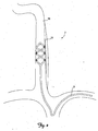
- FIG. 1 shows a perspective view of a patient's vascular system 2 including a lead 6 deployed within the system 2.
- FIG. 2 is a close up schematic view of the lead 6 deployed within the system 2.
- the vascular system 2 includes the right and left external jugular veins 10 and 14, the right and left internal jugular veins 18 and 22, the right and left subclavian veins 26 and 30, portions of which are generally aligned with the right and left vagus nerves 34 and 38.
- the lead 6 is inserted into a patient's vasculature system through the left subclavian vein 30 and into the right internal jugular vein 18.
- the lead 6 is positioned in the right internal jugular vein 18 adjacent to the right vagus nerve 34.
- the lead 6 can be inserted and advanced into the vasculature system via the right subclavian vein 26.
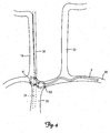
- FIGS. 3 and 4 show the lead 6 deployed within alternative locations in a patient's vasculature for stimulating the vagus nerve 34.
- the lead 6 is inserted through the right subclavian vein 30 deployed and secured in the superior vena cava 39.
- the portion of the vagus nerve 34 adjacent to the superior vena cava 39 is represented by the dashed lines in FIG. 3 .
- the lead 6 is inserted through the right subclavian vein 30 deployed and secured in the brachiocephalic vein 41.
- the portion of the vagus nerve 34 adjacent to the brachiocephalic vein 41 is represented by the dashed lines in FIG. 4 .
- FIG. 5 is a perspective view of a lead 6 according to an embodiment of the present invention.
- the lead 6 includes a lead body 42 including a proximal portion 46 and a distal portion 50 including one or more electrodes 66.
- One or more electrodes 66 are positioned along the lead body 42.
- the lead 6 includes a proximal end 52 adapted to be connected to a pulse generator or other implantable medical device.
- the lead body 42 is flexible, but substantially non-compressible along its length.
- the lead body 42 includes a plurality of conductors including individual wires, coils, or cables. These wires can be insulated conductive wires and/or molded in place with an insulator such as silicone, polyurethane, ethylene tetrafluoroethylene, or another biocompatible, insulative polymer. In one embodiment of the present invention, the lead body 42 has a co-radial design. In this embodiment, each individual conductor can be a coil including an insulative tubing. The insulated coils are then wound together in parallel to form a single coil. Alternatively, the lead body 42 is co-axial.
- each conductor is adapted to connect to an individual electrode 66 in a one-to-one manner allowing each electrode 66 to be individually addressable.
- the lead body 42 includes a lumen adapted to receive a guiding element such as a guidewire or a stylet.
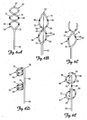
- FIGS. 6A-6E show the distal portion 50 of the lead 6 according to various embodiments of the present invention.
- the distal portion 50 is bifurcated at one or more bifurcation points 70 along the lead body 42.
- the distal portion 50 of the lead 6 is stiffer than the lead body 42 and the proximal portion 46.
- the distal portion 50 includes a superelastic material.
- Exemplary superelastic materials include Nitinol and MP35N.
- the bifurcated distal portion 50 includes at least a first elongate member 72 and a second elongate member 76.
- the first elongate member 72 forms a first spiral 82 and the second elongate member 76 forms a second spiral 86.
- Multiple spirals improve stability of the distal portion 50 of the lead 6 within the vessel by placing more friction against the venous walls. Additionally, multiple spirals fill out the space within a vessel lumen to form a tube-like inner support structure, increasing the stability of the lead in the vessel and decreasing a preference for a particular orientation.
- the spirals 82 and 86 are congruent, anti-parallel spirals having the same longitudinal axis intertwining to.form a double helix.
- the elongate members 72, 76 are connected to one another at a distal end 56 of the lead 6. Alternatively, the elongate members are not attached to one another at the distal end 56 of the lead 6.
- the spirals 82 and 86 are in serial alignment with one another. That is, as shown in FIGS. 6D and 6E , spiral 82 is proximate to spiral 86.
- the spirals 82 and 86 are interrupted by a generally straight portion 90.
- the generally straight portion 90 is configured such that it runs parallel to the nerve to be stimulated.
- a typical length of the straight portion 90 ranges from about 1 to about 8 cm as measured from a first bifurcation point to a second bifurcation point.
- the spirals 82 and 86 can wind in a clockwise or counter-clockwise direction.
- the number of turns can range from 1 ⁇ 2 turn to multiple turns as shown in FIGS. 6A and 6D .
- the pitch can be described as the distance between two points on a spiral.
- the pitch frequency ranges from zero (lasso configuration) to 5 cm, and can remain constant or vary along the spirals 82, 86.
- the spirals 82, 86 have a predetermined effective outer diameter ranging from about 5 mm to about 50 mm. According to another embodiment of the present invention, the predetermined effective outer diameter of the spirals 82, 86 ranges from about 10 mm to about 35 mm.
- the spirals 82, 86 can assume a variety of cross-sectional shapes. According to one embodiment, the spirals 82, 86 have a circular cross-sectional shape. A circular cross-sectional shape allows no bias for orientation such that when the lead is rotated within a vein the spirals 82, 86 exhibit no natural preference for a specific orientation. According to another embodiment, the spirals 82, 86 have an elliptical cross-sectional shape. The overall size, diameter and cross-sectional shape of the spirals 82, 86 can be selected depending upon the size, diameter, and shape of the vessel in which the distal portion 50 of the lead 6 is to be deployed.
- An overall length of each spiral 82, 86 ranges from about 30 mm to about 200 mm depending on the anatomical demands of the patient's anatomy. More particularly, an overall length of each spiral 82, 86 can range from about 40 to about 80 mm.
- spirals 82, 86 can increase in diameter from a proximal end of the spiral to a distal end of the spiral creating spirals 82, 86 having a predetermined shape that tapers down from a distal end of the spirals 82, 86 to a proximal end of the spirals 82, 86.
- spirals 82, 86 can have a diameter that decreases from a proximal end of spirals 82, 86 to a distal end of spirals 82, 86, creating spirals 82, 86 having a predetermined shape that tapers down from a proximal end of spirals 82, 86 towards the distal end of the spirals 82, 86.
- the spirals 82, 86 are adapted to transition from a collapsed configuration to an expanded configuration. In their expanded configuration, the spirals 82, 86 have a predetermined effective diameter and are adapted to frictionally engage at least one wall of the vessel in which the distal portion 50 is deployed. According to one embodiment of the present invention, when allowed to expand within a vessel, the spirals 82, 86 will not achieve their predetermined effective diameter as the spirals 82, 86 will be constrained from fully expanding by the walls of the vessel in which they are deployed. As such the spirals 82, 86 place a radial expansion force on the walls of the vessel, providing a mechanism for stabilizing the distal portion 50 of the lead 6 in the vessel. In one exemplary embodiment, the effective outer diameter ranges from about 5 percent to about 50 percent greater than the inner diameter of the vessel in which the distal portion 50 of the lead 6 is deployed.
- one or both of the elongate members 72, 76 can include a lumen adapted to receive a guiding element such as a stylet or a guidewire adapted to assist in delivery of the distal portion 50 to a stimulation site within a vessel.
- a guide catheter is provided to deliver the distal portion 50 to a stimulation site within a vessel.
- the stylet, guidewire, or guide catheter either alone or in combination with one another, is used to collapse (either fully or partially) the distal portion 50 including the spirals 82, 86 from an expanded configuration to a collapsed configuration (full or partial) and also to guide the distal portion 50 of the lead through the patient's vasculature system.
- the distal portion 50 can be inserted into a patient's vasculature and guided to a stimulation site within a vessel.
- the guiding element is removed, allowing the distal portion 50 to transition from a collapsed configuration to an expanded configuration.
- a guide catheter is used to deliver the distal portion 50 of the lead 6 to the stimulation site within a vessel.
- the distal portion can be partially deployed from the guide catheter and rotated or otherwise manipulated.
- the electrodes located on the distal portion can be used to acutely stimulate and thus, test potential stimulation sites.
- the guide catheter can be fully retracted and the distal portion deployed so as to secure and stabilize the distal portion at a stimulation site within the vessel such that stimulation can occur at the targeted stimulation site.
- the distal portion 50 includes a pull wire 92.
- the pull wire 92 is coupled to the distal end of the lead 6, and is operable at the proximal end of the lead 6.
- the pull wire 92 is disposed within a lumen of the lead body 42 and is adapted to be secured at the proximal end of the lead 6. Pulling on the pull wire 92 causes the distal portion 50 including the spirals 82, 86 to further expand within the vessel, causing additional radial expansion force to be placed on the vessel walls further stabilizing the distal portion 50 of the lead 6 within the vessel.
- the pull wire 92 can be secured at the proximal end of the lead 6.
- the tension placed on the pull wire 92 at the proximal end can be released, thus releasing any additional expansion force placed on the vessel walls by activating the pull wire 92 causing further radial expansion of the distal portion 50.
- a guiding element or a combination of guiding elements then can be used to reposition and/or remove the distal portion of the lead from the vessel.
- the spirals 82, 86 are variably expandable. That is, the spirals 82, 86 are adapted to expand with and adapt to the natural changes in the size and diameter of the vessel while at the same time engaging and maintaining a frictional force on the vessel walls.
- the internal geometry (diameter and inner shape) of the internal jugular vein may change with blood flow and blood pressure.
- the diameter of the vessel may be smaller than when the patient is lying down or is in a prone position.
- the spirals 82, 86 account for the difference in vessel diameter by expanding so as to maintain a frictional force on the vessel walls securing and stabilizing the distal portion 50 in the vessel.
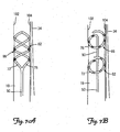
- FIGS. 7A and 7B are close-up schematic views of a distal portion 50 of a lead 6 deployed within the right internal jugular vein 18 adjacent the right vagus nerve 34.
- the spirals 82, 86 Upon deployment in a patient's vasculature, the spirals 82, 86 are adapted to radially expand such that they contact and frictionally engage an inner surface of vessel walls 102, 104 securing and stabilizing the distal portion 50 of the lead 6 at a stimulation site within the vessel.
- the stimulation site can be described as the location within a vessel adjacent a nerve or muscle which maximizes electrical stimulation to the nerve or muscle across a vessel wall.
- the spirals 82, 86 place enough radial expansion force on the vessel walls 102, 104 such that the turns of the spiral migrate outside of the original boundaries of the vessel walls 102, 104 and towards the nerve 34 to be stimulated without damaging the vessel walls 102, 104.
- any electrodes 66 located on the spirals 82, 86 are placed in closer proximity to the nerve 34.
- the electrode 66 is disposed at a distance of less than 2 mm from the nerve 34 to be stimulated.
- the spirals 82, 86 force the vessel walls 102, 104 into direct contact with the nerve 34.
- the migration of the spiral outside of the original boundaries of the vessel walls causes no damage to the vessel walls nor does the spiral erode through the vessel walls.
- a sheath of tissue forms over the spiral over an extended period of time such that it becomes encapsulated within the vessel walls.
- the outer geometry of the vessel is altered such that the outline of the spiral located within the vessel is visible.
- the lead 6 includes one or more electrodes 66.
- one or more electrodes 66 are located on one or both spirals 82, 86.
- one or more electrodes 66 are located on one or both spirals and/or the generally straight portion 90, as shown in FIG. 6E .
- At least one electrode 66 is adapted to deliver an electrical pulse transvascularly to the nerve or muscle to be stimulated.
- at least one electrode 66 is a pacing or a sensing electrode.
- stimulation can occur between electrodes 66 located on the same spiral 82 or 86, the straight portion 90, or between electrodes 66 located on different spirals 82 or 86 and/or the straight portion 90.
- the distal portion 50 is positioned within the vessel such that generally straight portion 90 is aligned in parallel along a portion of the vagus nerve 34.
- one or both spirals 82, 86 include multiple electrodes 66.
- the electrodes 66 can have the same or different polarity. Multiple electrodes 66 allow flexibility in the intravascular placement of the distal portion 50 of the lead 6. Not all of the electrodes 66 need to be orientated towards the adjacent nerve or muscle tissue in order for maximum stimulation across the vessel wall to occur.
- the circular or elliptical cross section of the spirals 82, 86 allow the distal portion 50 of the lead 6 to be rotated within the vessel so as to ensure that at least one electrode 66 is capable of delivering sufficient electrical stimulating pulse across the vessel wall.
- the electrodes 66 can be connected to multiple individual conductors through the lead body 42 allowing for them to be individually addressable.
- Individually addressable electrodes 66 allow for flexibility in electrode selection. It also allows for stimulation to occur between individual electrodes 66 on the same spiral 82 or 86 or different spirals 82 or 86 and/or the straight portion 90 providing for greater control over the current field and the direction of stimulation as well as allowing for multiple options for stimulation and sensing.
- multiple electrodes 66 are provided at an equal distance from one another along each elongate member 72, 76.
- the electrodes 66 need not have an equal spacing from one electrode 66 to another.
- the electrodes 66 are located on the straight portion 90 that interrupts the spirals 82, 86, and as such can be aligned in parallel with the nerve to be stimulated. Parallel alignment of the electrodes with the adjacent nerve increases the efficacy of stimulation as the nerve is stimulated when the electrical potential changes along the nerve.
- the lead body 42 including.the spirals 82, 86 can be rotated or otherwise manipulated such that the electrical stimulation across the vessel walls 102, 104 to the adjacent nerve is maximized.
- the electrodes 66 are pushed up against the vessel walls 102, 104, maximizing electrical transvascular stimulation.
- the spirals 82, 86 press up against the vessel walls 102, 104 with enough radial expansion force such that the spiral 82, 86 migrates outside the original boundaries of the vessel wall bringing at least one electrode 66 in closer proximity to the adjacent nerve.
- the electrodes 66 located on the lead body 42 can have any electrode configuration as is known in the art. According to one embodiment of the present invention, the electrodes 66 are ring electrodes. According to another embodiment, the electrodes 66 are partial ring electrodes. According to yet another embodiment of the present invention, the electrodes include an exposed electrode portion and an insulated electrode portion. According to this embodiment, the electrodes 66 are masked or otherwise insulated on the inner circumference of the spirals 82, 86 The exposed electrode portion is located on the outer circumference of the spiral 82, 86. Exemplary electrodes of this type are described in commonly owned and co-pending application entitled "ELECTRODE CONFIGURATIONS FOR TRANSVASCULAR NERVE STIMULATION,” assigned Serial No. 11/668,957 .
- the lead body 42 is rotated such that the exposed electrode portion is oriented towards the adjacent nerve, muscle or tissue to be stimulated.
- the exposed electrode portion is configured such that it is adapted to direct or focus current towards the stimulation target.
- the insulated electrode portion is located on the lead body 42 opposite the exposed electrode surface. The insulated electrode portion acts as a shield from the undesired stimulation of an adjacent or nearby nerve or muscle that is not the stimulation target.
- the lead 6 can be further stabilized in the internal jugular vein 34 by using a suture in a distal region of the lead body 42.
- the lead 6 is further stabilized through the wearing of a neck brace by the patient for a period of time after implantation of the lead 6.
- the lead 6 can include fixation features well known in the art, such as silicone tines or a corkscrew-shaped fixation feature (not shown) at the distal region of the lead body 42, to stabilize the lead 6 in the internal jugular vein 34.
- the fixation features can be located on one or both of the spirals 82, 86.
- the fixation feature can be located at a distal end 56 of the lead 6.
- the lead 6 can also include an area on the lead body 42 that promotes tissue in-growth.
- the area includes a roughened polymer surface on the lead body 42.
- the area includes a region of stepped or inset diameter within the lead body 42, within an electrode, or between the lead body 42 and an electrode.
- the area includes a polymer mesh, for example, a Dacron mesh, a metal mesh, for example, a stainless steel or nitinol mesh, or a bio-absorbable mesh. Examples of a bio-absorbable mesh include polyglycolic acid, poly-lactic acid, and polydioxanone.
- the lead 6 can include any combination of sutures, fixation devices, tissue in-growth areas, or a neck brace to improve its stability within the internal jugular vein 34.
- the lead 6, can be delivered to a stimulation site within a vessel adjacent a nerve, muscle, or tissue to be stimulated using standard techniques.
- the lead 6 can be inserted in a patient's vasculature system via percutaneous stick directly into a patient's internal jugular vein to deliver therapy to the vagus nerve.
- the distal portion 50 of the lead 6 is transitioned to a collapsed configuration and advanced through a patient's vasculature and delivered to a stimulation site using a guiding element such as a guide catheter.
- the spirals located at the distal portion 50 of the lead 6 transition from their collapsed configuration to their expanded configuration contacting and frictionally engaging the vessel walls of the vessel in which it is deployed.
- a stylet or one or more guidewires may be inserted into the lead lumen and/or a lumen located within one of the elongate members 72 or 76 to straighten the distal portion 50 from its predetermined spiral shape. The distal portion is then guided through the vasculature to a stimulation site located within a vessel.
- the guidewire or stylet is removed allowing the distal portion 50 of the lead 6 to return to its predetermined shape.
- Pull wires can also be used to further expand the spirals in a vessel such that they place an additional radial force on the wall further securing and stabilizing the distal portion 50 within the vessel.
- the distal portion 50 expands, contacting and frictionally engaging the vessel walls of the vessel in which it is deployed.
- the lead body 42 and, thus, the spiral members 82, 86 can be rotated within the vessel to orient the electrodes 66 towards the stimulation target. Additionally, the lead body 42 can be further rotated or positioned until a maximum or optimum electrical stimulation threshold by the electrodes 66 has been achieved across the vessel wall to the adjacent nerve or muscle to be stimulated. The stimulating pulse delivered by the electrodes can then be measured to determine if an optimal stimulation threshold has been reached, The lead 6 can be repositioned within the vessel by either rotating the lead body 42 within the vessel or reintroducing the guiding member such as the guide catheter or guidewire to collapse and/or straighten the distal portion 50 of the lead 6.
- the lead 6 can then either be repositioned and/or removed from the vessel.
- the distal portion can be partially deployed from a guide catheter in order to acutely stimulate the electrodes. Once a suitable stimulation site has been identified, the guide catheter can be retracted and the distal portion 50 fully deployed within the vessel at the stimulation site.
Landscapes
- Health & Medical Sciences (AREA)
- Cardiology (AREA)
- Heart & Thoracic Surgery (AREA)
- Life Sciences & Earth Sciences (AREA)
- General Health & Medical Sciences (AREA)
- Biomedical Technology (AREA)
- Nuclear Medicine, Radiotherapy & Molecular Imaging (AREA)
- Radiology & Medical Imaging (AREA)
- Veterinary Medicine (AREA)
- Animal Behavior & Ethology (AREA)
- Engineering & Computer Science (AREA)
- Public Health (AREA)
- Vascular Medicine (AREA)
- Neurology (AREA)
- Neurosurgery (AREA)
- Orthopedic Medicine & Surgery (AREA)
- Electrotherapy Devices (AREA)
Claims (13)
- Conduit intravasculaire adaptée pour être déployée sur un site de stimulation dans un veine jugulaire interne ayant une paroi de vaisseau adjacente à un nerf vague, le conduit comprenant :un corps de conduit incluant une extrémité proximale adaptée pour être connectée à un générateur d'impulsions et une partie distale bifurquée pour fixer et stabiliser le conduit dans le vaisseau, la partie distale bifurquée comprenant au moins un point de bifurcation et un premier élément allongé et un second élément allongé, les premier et second éléments allongés se branchant de façon à s'éloigner et s'étendre distalement depuis l'au moins un point de bifurcation, le premier élément allongé formant une première spirale et le second élément allongé formant une seconde spirale, dans lequel les première et seconde spirales sont des spirales congruentes et anti-parallèles ayant le même axe longitudinal formant une double hélice et dans lequel les spirales sont adaptées pour former une transition depuis une configuration affaissée pour permettre l'insertion du conduit au travers d'un système vasculaire de patient jusqu'à une configuration dilatée, dans lequel dans la configuration dilatée, les spirales ont un diamètre externe effectif prédéterminé dans la plage d'environ 5 à 50 % plus grand que le diamètre interne de la veine jugulaire interne et sont adaptées pour entrer en contact avec friction avec la paroi du vaisseau dans lequel la partie distale est déployée ;une pluralité de conducteurs inclus dans le corps de conduit ;une pluralité d'électrodes adaptées pour délivrer une impulsion éclectique transvasculairement sur le nerf situé sur la partie distale, chaque électrode individuelle comprenant une partie masquée et une partie exposée et étant couplée à un conducteur individuel de telle sorte que chaque électrode soit adressable individuellement, dans laquelle lorsque la partie distale est dilatée, la partie exposée d'au moins une électrode est située sur une circonférence externe d'au moins une spirale et est adaptée pour être orientée dans une direction vers le nerf vague et la partie masquée est située sur une circonférence interne de l'au moins une spirale.
- Conduit intravasculaire selon la revendication 1, dans lequel au moins une première électrode est située sur la première spirale et au moins une seconde électrode est située sur la seconde spirale.
- Conduit intravasculaire selon la revendication 1, dans lequel les spirales ont un diamètre effectif externe dans la plage d'environ 5 % à environ 20 % plus grand qu'un diamètre interne de la veine jugulaire interne dans laquelle la partie distale est déployée.
- Conduit intravasculaire selon la revendication 1, dans lequel lorsque la partie distale est dilatée, les parties exposée d'au moins deux électrodes sont orientée dans une direction vers le nerf vague et sont adaptées pour être alignées avec ce nerf vague.
- Conduit intravasculaire selon la revendication 1, dans lequel la partie distale est adaptée pour pousser la paroi de vaisseau dans une direction vers le nerf vague de telle sorte qu'une distance entre une ou plusieurs électrodes et le nerf vague soit inférieure à 2 mm.
- Conduit intravasculaire selon la revendication 1, dans lequel la partie distale comprend un matériau superélastique choisi parmi le groupe comprenant Nitinol et MP35N.
- Conduit intravasculaire selon la revendication 1, comprenant en outre un fil de traction fixé à une partie distale du conduit.
- Conduit intravasculaire adaptée pour être déployée sur un site de stimulation dans un veine jugulaire interne ayant une paroi de vaisseau adjacente à un nerf vague, le conduit comprenant :un corps de conduit incluant une extrémité proximale adaptée pour être connectée à un générateur d'impulsions et une partie distale bifurquée, la partie distale bifurquée comprenant au moins un point de bifurcation, pour fixer et stabiliser le conduit dans le vaisseau, la partie distale bifurquée comprenant au moins un point de bifurcation, un premier élément allongé formant une première spirale, une second élément allongé formant une seconde spirale, dans lequel les premier et second éléments allongés se branchent de façon à s'éloigner et s'étendre distalement depuis l'au moins un point de bifurcation, et une partie de forme générale droite étant présente entre la première spirale et la seconde spirale, dans lequel chacune des première et seconde spirales présente un diamètre externe effectif prédéterminé dans la plage d'environ 5 à 50 % plus grand que le diamètre interne de la veine jugulaire interne et sont adaptées pour se dilater pour appliquer une force latérale sur la paroi de vaisseau afin de pousser la paroi de vaisseau dans une direction vers le nerf vague et pour fixer et stabiliser la partie distale dans le vaisseau ; une pluralité de conducteurs s'étendant dans le corps de conduit depuis l'extrémité proximale jusqu'à l'extrémité distale ; etau moins une première électrode située sur la première spirale et au moins une seconde électrode située sur la seconde spirale, chacune des première et seconde électrodes étant couplée à une conducteur individuel s'étendant dans le corps de conduit et adapté pour délivrer une impulsion électrique transvasculairement sur le nerf vague et chaque électrode comprenant une partie masquée et une partie exposée, dans lequel lorsque la partie distale est dilatée, la partie exposée d'au moins la première électrode est située sur une circonférence externe de la première spirale et est adaptée pour être orientée dans une direction vers le nerf vague et la partie masquée est située sur une circonférence interne de la première spirale.
- Conduit intravasculaire selon la revendication 8, dans lequel le second élément allongé comprend un fil super-élastique.
- Conduit intravasculaire selon la revendication 8, dans lequel les première et seconde électrodes sont alignées avec chaque autre de telle sorte qu'elles soient adaptées pour être alignées en parallèle avec le nerf à stimuler.
- Conduit intravasculaire selon la revendication 8, dans lequel la première spirale est en alignement série avec la seconde spirale.
- Conduit intravasculaire selon la revendication 8, dans lequel les spirales sont configurées pour se dilater et entrer en contact de friction avec au moins une paroi de vaisseau lors du déploiement dans un vaisseau.
- Conduit intravasculaire selon la revendication 8, dans lequel la partie distale comprend un matériau superélastique choisi parmi le groupe comprenant Nitinol et MP35N.
Applications Claiming Priority (2)
| Application Number | Priority Date | Filing Date | Title |
|---|---|---|---|
| US11/668,887 US7949409B2 (en) | 2007-01-30 | 2007-01-30 | Dual spiral lead configurations |
| PCT/US2007/086119 WO2008094345A1 (fr) | 2007-01-30 | 2007-11-30 | Configurations de dérivation à double spirale |
Publications (2)
| Publication Number | Publication Date |
|---|---|
| EP2125105A1 EP2125105A1 (fr) | 2009-12-02 |
| EP2125105B1 true EP2125105B1 (fr) | 2015-08-05 |
Family
ID=39181269
Family Applications (1)
| Application Number | Title | Priority Date | Filing Date |
|---|---|---|---|
| EP07865019.9A Not-in-force EP2125105B1 (fr) | 2007-01-30 | 2007-11-30 | Configurations de dérivation à double spirale |
Country Status (6)
| Country | Link |
|---|---|
| US (1) | US7949409B2 (fr) |
| EP (1) | EP2125105B1 (fr) |
| JP (1) | JP5150646B2 (fr) |
| CN (1) | CN101610810A (fr) |
| AU (1) | AU2007345602B2 (fr) |
| WO (1) | WO2008094345A1 (fr) |
Families Citing this family (93)
| Publication number | Priority date | Publication date | Assignee | Title |
|---|---|---|---|---|
| US8862243B2 (en) | 2005-07-25 | 2014-10-14 | Rainbow Medical Ltd. | Electrical stimulation of blood vessels |
| US20070123923A1 (en) * | 2005-11-30 | 2007-05-31 | Lindstrom Curtis C | Implantable medical device minimizing rotation and dislocation |
| US9186511B2 (en) | 2006-10-13 | 2015-11-17 | Cyberonics, Inc. | Obstructive sleep apnea treatment devices, systems and methods |
| US9744354B2 (en) | 2008-12-31 | 2017-08-29 | Cyberonics, Inc. | Obstructive sleep apnea treatment devices, systems and methods |
| US9913982B2 (en) | 2011-01-28 | 2018-03-13 | Cyberonics, Inc. | Obstructive sleep apnea treatment devices, systems and methods |
| US8855771B2 (en) | 2011-01-28 | 2014-10-07 | Cyberonics, Inc. | Screening devices and methods for obstructive sleep apnea therapy |
| US9205262B2 (en) | 2011-05-12 | 2015-12-08 | Cyberonics, Inc. | Devices and methods for sleep apnea treatment |
| ES2722849T3 (es) | 2006-10-13 | 2019-08-19 | Cyberonics Inc | Dispositivos y sistemas para el tratamiento de apnea obstructiva del sueño |
| US8909341B2 (en) * | 2007-01-22 | 2014-12-09 | Respicardia, Inc. | Device and method for the treatment of breathing disorders and cardiac disorders |
| EP2107920B1 (fr) | 2007-01-29 | 2013-07-10 | Simon Fraser University | Appareil de neurostimulation transvasculaire |
| US20080183187A1 (en) * | 2007-01-30 | 2008-07-31 | Cardiac Pacemakers, Inc. | Direct delivery system for transvascular lead |
| US8244378B2 (en) | 2007-01-30 | 2012-08-14 | Cardiac Pacemakers, Inc. | Spiral configurations for intravascular lead stability |
| US20080183255A1 (en) * | 2007-01-30 | 2008-07-31 | Cardiac Pacemakers, Inc. | Side port lead delivery system |
| US7917230B2 (en) | 2007-01-30 | 2011-03-29 | Cardiac Pacemakers, Inc. | Neurostimulating lead having a stent-like anchor |
| US20080183265A1 (en) * | 2007-01-30 | 2008-07-31 | Cardiac Pacemakers, Inc. | Transvascular lead with proximal force relief |
| US20080183264A1 (en) * | 2007-01-30 | 2008-07-31 | Cardiac Pacemakers, Inc. | Electrode configurations for transvascular nerve stimulation |
| US9987488B1 (en) | 2007-06-27 | 2018-06-05 | Respicardia, Inc. | Detecting and treating disordered breathing |
| US8135471B2 (en) | 2007-08-28 | 2012-03-13 | Cardiac Pacemakers, Inc. | Method and apparatus for inspiratory muscle stimulation using implantable device |
| US8538535B2 (en) | 2010-08-05 | 2013-09-17 | Rainbow Medical Ltd. | Enhancing perfusion by contraction |
| US9199075B1 (en) | 2008-02-07 | 2015-12-01 | Respicardia, Inc. | Transvascular medical lead |
| US7925352B2 (en) | 2008-03-27 | 2011-04-12 | Synecor Llc | System and method for transvascularly stimulating contents of the carotid sheath |
| US20100137949A1 (en) * | 2008-05-27 | 2010-06-03 | The Cleveland Clinic Foundation | Bifurcated electrical lead and method of use |
| US8340767B2 (en) * | 2008-08-12 | 2012-12-25 | Cardiac Pacemakers, Inc. | Implantable lead and coronary venous pressure sensor apparatus and method |
| EP3714771A1 (fr) | 2008-10-01 | 2020-09-30 | Inspire Medical Systems, Inc. | Système de traitement de l'apnée du sommeil par voie transveineuse |
| US8652129B2 (en) | 2008-12-31 | 2014-02-18 | Medtronic Ardian Luxembourg S.A.R.L. | Apparatus, systems, and methods for achieving intravascular, thermally-induced renal neuromodulation |
| JP2012521864A (ja) | 2009-03-31 | 2012-09-20 | インスパイア・メディカル・システムズ・インコーポレイテッド | 睡眠に関連する異常呼吸を処置するシステムにおける経皮的アクセス方法 |
| US8233987B2 (en) | 2009-09-10 | 2012-07-31 | Respicardia, Inc. | Respiratory rectification |
| US9468755B2 (en) * | 2009-09-30 | 2016-10-18 | Respicardia, Inc. | Medical lead with preformed bias |
| EP2550059B1 (fr) * | 2010-03-23 | 2016-01-06 | Boston Scientific Neuromodulation Corporation | Espacement radial hélicoïdal des contacts sur un conducteur cylindrique |
| AU2011282294B9 (en) | 2010-07-19 | 2014-09-25 | Cardiac Pacemakers, Inc. | Minimally invasive lead system for vagus nerve stimulation |
| EP2701795B1 (fr) | 2011-04-28 | 2020-12-09 | Interventional Autonomics Corporation | Systèmes de neuromodulation pour traiter des syndromes d'insuffisance cardiaque aiguë |
| US9220887B2 (en) * | 2011-06-09 | 2015-12-29 | Astora Women's Health LLC | Electrode lead including a deployable tissue anchor |
| US9446240B2 (en) | 2011-07-11 | 2016-09-20 | Interventional Autonomics Corporation | System and method for neuromodulation |
| AU2012299373A1 (en) * | 2011-07-11 | 2014-02-27 | Interventional Autonomics Corporation | System and method for neuromodulation |
| US20130072995A1 (en) | 2011-07-11 | 2013-03-21 | Terrance Ransbury | Catheter system for acute neuromodulation |
| JP2013034535A (ja) * | 2011-08-04 | 2013-02-21 | Olympus Corp | 電気刺激電極組立体 |
| WO2013035092A2 (fr) | 2011-09-09 | 2013-03-14 | Enopace Biomedical Ltd. | Électrodes basées sur un stent endovasculaire sans fil |
| JP6149269B2 (ja) * | 2011-10-04 | 2017-06-21 | スマートステント ピーティーワイ リミテッド | 組織の活動の感知又は刺激 |
| US20140324142A1 (en) * | 2011-11-08 | 2014-10-30 | Enopace Biomedical Ltd. | Acute myocardial infarction treatment by electrical stimulation of the thoracic aorta |
| ITPD20110383A1 (it) * | 2011-12-05 | 2013-06-06 | Cardiac Impulse Srl | Elettrocatetere per neurostimolazione |
| US20130184801A1 (en) * | 2012-01-13 | 2013-07-18 | Pacesetter, Inc. | Lead shaped for stimulation at the base left ventricle |
| BR112014021930A2 (pt) | 2012-03-05 | 2020-06-23 | Simon Fraser University | Sistema de eletrodos intravasculares, aparelho para estimulação de nervos, e, estrutura de eletrodo |
| JP5936409B2 (ja) * | 2012-03-26 | 2016-06-22 | 国立研究開発法人国立循環器病研究センター | 電極ユニットおよび組織刺激システム |
| US9439598B2 (en) | 2012-04-12 | 2016-09-13 | NeuroMedic, Inc. | Mapping and ablation of nerves within arteries and tissues |
| US11395921B2 (en) * | 2012-04-29 | 2022-07-26 | Nuxcel2 Llc | Intravascular electrode arrays for neuromodulation |
| JP6359528B2 (ja) | 2012-06-21 | 2018-07-18 | ラングペーサー メディカル インコーポレイテッドLungpacer Medical Inc. | 経血管横隔膜ペーシング・システム及び使用方法 |
| DE102013105010B4 (de) * | 2013-05-15 | 2020-09-10 | Bildungszentrum für informationsverarbeitende Berufe gGmbH | Messsystem, Anordnung und Verfahren zur Auswertung von Nervensignalen |
| US9370652B2 (en) | 2013-07-24 | 2016-06-21 | Gimer Medical Co. Ltd. | Desensitizing device |
| CN104415454B (zh) * | 2013-08-26 | 2017-11-03 | 精能医学股份有限公司 | 改变神经阈值的高频电磁场刺激器 |
| CN104510527B (zh) * | 2013-09-29 | 2017-04-12 | 柯惠有限合伙公司 | 具有可调节长度和/或直径的医疗装置 |
| WO2015042900A1 (fr) | 2013-09-29 | 2015-04-02 | Covidien Lp | Dispositifs de traitement médical présentant une longueur et/ou un diamètre ajustables |
| US9526889B2 (en) | 2013-10-09 | 2016-12-27 | GiMer Medical Co., Ltd. | Electromagnetic stimulation device for changing nerve threshold |
| US9956408B2 (en) | 2013-10-09 | 2018-05-01 | Gimer Medical Co. Ltd. | Method for reducing spasticity and non-transitory computer-readable medium thereof |
| US10183165B2 (en) | 2013-10-09 | 2019-01-22 | GiMer Medical Co., Ltd. | Method of reducing renal hypertension and computer-readable medium |
| US10086201B2 (en) | 2013-10-09 | 2018-10-02 | GiMer Medical Co., Ltd. | Electronic stimulation device, method of treatment and electronic stimulation system |
| US10086197B2 (en) | 2013-10-09 | 2018-10-02 | GiMer Medical Co., Ltd. | Method for reducing overactive bladder syndrome and computer-readable medium thereof |
| US10639476B2 (en) | 2013-10-09 | 2020-05-05 | GiMer Medical Co., Ltd. | Electronic stimulation device, method of treatment and electronic stimulation system |
| US10632310B2 (en) | 2013-10-09 | 2020-04-28 | GiMer Medical Co., Ltd. | Electronic stimulation device, method of treatment and electronic stimulation system |
| CN105899166B (zh) | 2013-11-06 | 2018-07-06 | 伊诺佩斯生医有限公司 | 无线型血管内基于支架的电极 |
| US9242088B2 (en) | 2013-11-22 | 2016-01-26 | Simon Fraser University | Apparatus and methods for assisted breathing by transvascular nerve stimulation |
| CA2935454A1 (fr) | 2014-01-21 | 2015-07-30 | Simon Fraser University | Systemes et procedes associes pour optimiser une stimulation de nerf a multiples electrodes |
| WO2015123360A1 (fr) | 2014-02-11 | 2015-08-20 | Cyberonics, Inc. | Systèmes et des procédés de détection et de traitement de l'apnée obstructive du sommeil |
| JP6639406B2 (ja) * | 2014-03-09 | 2020-02-05 | ニューロトロニク アイ・ピー ホールディング (ジャージー) リミテッド | 交感神経系および副交感神経系心臓神経の神経変調療法のためのシステムおよび方法 |
| JP6274972B2 (ja) * | 2014-05-29 | 2018-02-07 | オリンパス株式会社 | 医療用電気刺激電極及び医療用電気刺激装置 |
| US10743960B2 (en) | 2014-09-04 | 2020-08-18 | AtaCor Medical, Inc. | Cardiac arrhythmia treatment devices and delivery |
| US10328268B2 (en) | 2014-09-04 | 2019-06-25 | AtaCor Medical, Inc. | Cardiac pacing |
| JP2016077801A (ja) * | 2014-10-22 | 2016-05-16 | オリンパス株式会社 | 電極ユニットおよび神経刺激システム |
| US11097109B2 (en) | 2014-11-24 | 2021-08-24 | AtaCor Medical, Inc. | Cardiac pacing sensing and control |
| JP6632191B2 (ja) * | 2015-01-08 | 2020-01-22 | アドリアカイム株式会社 | 神経刺激電極 |
| JP6576367B2 (ja) * | 2015-01-13 | 2019-09-18 | アドリアカイム株式会社 | 神経刺激電極 |
| JP6438497B2 (ja) * | 2015-02-03 | 2018-12-12 | オリンパス株式会社 | 医療用電気刺激電極 |
| JP6491939B2 (ja) * | 2015-04-22 | 2019-03-27 | オリンパス株式会社 | 神経刺激システム |
| BR112018008121B1 (pt) | 2015-10-20 | 2023-02-07 | The University Of Melbourne | Dispositivo médico para uso no interior de um corpo tubular tendo um lúmen e sistema para o controle de um equipamento acoplado a um animal ou humano |
| US10335607B2 (en) | 2016-02-05 | 2019-07-02 | Boston Scientific Neuromodulation Corporation | Implantable optical stimulation lead and methods of making and using |
| EP3436140B1 (fr) | 2016-04-01 | 2021-01-06 | Cyberonics, Inc. | Sélection de patient pour la stimulation du nerf vague |
| WO2017173433A1 (fr) * | 2016-04-01 | 2017-10-05 | Tholakanahalli Venkatakrishna N | Dérivation épicardique modelée et système et procédé de placement |
| DE102016116871A1 (de) * | 2016-09-08 | 2018-03-08 | Phenox Gmbh | Vorrichtung und Verfahren zur Vorbeugung und Behandlung eines Vasospasmus |
| CN111132726B (zh) | 2017-04-18 | 2023-10-31 | 墨尔本大学 | 用于感测和/或刺激组织的血管内设备 |
| US10293164B2 (en) | 2017-05-26 | 2019-05-21 | Lungpacer Medical Inc. | Apparatus and methods for assisted breathing by transvascular nerve stimulation |
| US20190001127A1 (en) | 2017-06-30 | 2019-01-03 | Lungpacer Medical Inc. | Devices and methods for prevention, moderation, and/or treatment of cognitive injury |
| US10195429B1 (en) | 2017-08-02 | 2019-02-05 | Lungpacer Medical Inc. | Systems and methods for intravascular catheter positioning and/or nerve stimulation |
| US10940308B2 (en) | 2017-08-04 | 2021-03-09 | Lungpacer Medical Inc. | Systems and methods for trans-esophageal sympathetic ganglion recruitment |
| US20190175908A1 (en) | 2017-12-11 | 2019-06-13 | Lungpacer Medical Inc. | Systems and methods for strengthening a respiratory muscle |
| WO2019183068A1 (fr) | 2018-03-23 | 2019-09-26 | Boston Scientific Neuromodulation Corporation | Système de stimulation optique doté d'une surveillance à la demande et procédés de fabrication et d'utilisation |
| US11565131B2 (en) | 2018-03-23 | 2023-01-31 | Boston Scientific Neuromodulation Corporation | Optical stimulation systems with calibration and methods of making and using |
| EP3877043A4 (fr) | 2018-11-08 | 2022-08-24 | Lungpacer Medical Inc. | Systèmes de stimulation et interfaces utilisateur associées |
| EP3840824A1 (fr) | 2018-11-16 | 2021-06-30 | Boston Scientific Neuromodulation Corporation | Système de stimulation optique avec surveillance à la demande et procédés de fabrication |
| JP2022532375A (ja) | 2019-05-16 | 2022-07-14 | ラングペーサー メディカル インコーポレイテッド | 検知及び刺激のためのシステム及び方法 |
| EP3976167A1 (fr) | 2019-05-29 | 2022-04-06 | Atacor Medical, Inc. | Fils électriques implantables et systèmes de mise en place associés |
| WO2020252037A1 (fr) | 2019-06-12 | 2020-12-17 | Lungpacer Medical Inc. | Circuit pour systèmes de stimulation médicale |
| US11666771B2 (en) | 2020-05-29 | 2023-06-06 | AtaCor Medical, Inc. | Implantable electrical leads and associated delivery systems |
| US11806547B2 (en) | 2020-09-04 | 2023-11-07 | Boston Scientific Neuromodulation Corporation | Stimulation systems with a lens arrangement for light coupling and methods of making and using |
| US11400299B1 (en) | 2021-09-14 | 2022-08-02 | Rainbow Medical Ltd. | Flexible antenna for stimulator |
Citations (3)
| Publication number | Priority date | Publication date | Assignee | Title |
|---|---|---|---|---|
| US4154247A (en) * | 1977-04-01 | 1979-05-15 | Medtronic, Inc. | Formable cardiac pacer lead and method of assembly and attachment to a body organ |
| DE10103288A1 (de) * | 2001-01-25 | 2002-08-01 | Patrick Schauerte | Gefäßschleuse zur intravaskulären Nervenstimulation und Flüssigkeitsinfusion |
| US20060229677A1 (en) * | 2005-04-11 | 2006-10-12 | Cardiac Pacemakers, Inc. | Transvascular neural stimulation device |
Family Cites Families (109)
| Publication number | Priority date | Publication date | Assignee | Title |
|---|---|---|---|---|
| US4365634A (en) * | 1979-12-06 | 1982-12-28 | C. R. Bard, Inc. | Medical electrode construction |
| US4414986A (en) * | 1982-01-29 | 1983-11-15 | Medtronic, Inc. | Biomedical stimulation lead |
| US4774949A (en) * | 1983-06-14 | 1988-10-04 | Fogarty Thomas J | Deflector guiding catheter |
| DE3715699A1 (de) * | 1987-05-12 | 1988-12-01 | Foerster Ernst | Katheter und endoskop zur transpapillaeren darstellung der gallenblase |
| US4944088A (en) * | 1988-05-25 | 1990-07-31 | Medtronic, Inc. | Ring electrode for multiconductor pacing leads |
| US4920979A (en) * | 1988-10-12 | 1990-05-01 | Huntington Medical Research Institute | Bidirectional helical electrode for nerve stimulation |
| US5016808A (en) * | 1989-09-14 | 1991-05-21 | Cardiac Pacemakers, Inc. | Implantable tapered spiral endocardial lead for use in internal defibrillation |
| US5265608A (en) * | 1990-02-22 | 1993-11-30 | Medtronic, Inc. | Steroid eluting electrode for peripheral nerve stimulation |
| US5221261A (en) * | 1990-04-12 | 1993-06-22 | Schneider (Usa) Inc. | Radially expandable fixation member |
| US5251634A (en) * | 1991-05-03 | 1993-10-12 | Cyberonics, Inc. | Helical nerve electrode |
| JPH066170B2 (ja) * | 1991-08-28 | 1994-01-26 | 中島 博 | ペースメーカのペーシング・リード |
| US5330515A (en) * | 1992-06-17 | 1994-07-19 | Cyberonics, Inc. | Treatment of pain by vagal afferent stimulation |
| DE669839T1 (de) | 1992-10-01 | 1996-10-10 | Cardiac Pacemakers | Stentartige struktur für entflimmerungselektroden. |
| SE9203732D0 (sv) * | 1992-12-11 | 1992-12-11 | Siemens Elema Ab | Elektrodsystem foer defibrillator |
| SE9203733D0 (sv) * | 1992-12-11 | 1992-12-11 | Siemens Elema Ab | Defibrilleringselektrod |
| US5387233A (en) * | 1993-01-11 | 1995-02-07 | Incontrol, Inc. | Intravenous cardiac lead with improved fixation and method |
| US5792187A (en) * | 1993-02-22 | 1998-08-11 | Angeion Corporation | Neuro-stimulation to control pain during cardioversion defibrillation |
| US5383922A (en) * | 1993-03-15 | 1995-01-24 | Medtronic, Inc. | RF lead fixation and implantable lead |
| US5476498A (en) * | 1994-08-15 | 1995-12-19 | Incontrol, Inc. | Coronary sinus channel lead and method |
| US5540730A (en) * | 1995-06-06 | 1996-07-30 | Cyberonics, Inc. | Treatment of motility disorders by nerve stimulation |
| US5766203A (en) * | 1995-07-20 | 1998-06-16 | Intelliwire, Inc. | Sheath with expandable distal extremity and balloon catheters and stents for use therewith and method |
| US5772693A (en) * | 1996-02-09 | 1998-06-30 | Cardiac Control Systems, Inc. | Single preformed catheter configuration for a dual-chamber pacemaker system |
| US5776178A (en) | 1996-02-21 | 1998-07-07 | Medtronic, Inc. | Medical electrical lead with surface treatment for enhanced fixation |
| US5755761A (en) * | 1996-04-26 | 1998-05-26 | Pharmatarget, Inc. | Atrial pacing catheter and method having multiple electrodes in the right atrium and coronary sinus |
| US7269457B2 (en) * | 1996-04-30 | 2007-09-11 | Medtronic, Inc. | Method and system for vagal nerve stimulation with multi-site cardiac pacing |
| USRE38705E1 (en) * | 1996-04-30 | 2005-02-22 | Medtronic, Inc. | Method and device for electronically controlling the beating of a heart using venous electrical stimulation of nerve fibers |
| US7225019B2 (en) * | 1996-04-30 | 2007-05-29 | Medtronic, Inc. | Method and system for nerve stimulation and cardiac sensing prior to and during a medical procedure |
| US6006134A (en) * | 1998-04-30 | 1999-12-21 | Medtronic, Inc. | Method and device for electronically controlling the beating of a heart using venous electrical stimulation of nerve fibers |
| US6449507B1 (en) * | 1996-04-30 | 2002-09-10 | Medtronic, Inc. | Method and system for nerve stimulation prior to and during a medical procedure |
| US5755714A (en) | 1996-09-17 | 1998-05-26 | Eclipse Surgical Technologies, Inc. | Shaped catheter for transmyocardial revascularization |
| DE19645573A1 (de) * | 1996-11-05 | 1998-05-07 | Bodenseewerk Geraetetech | Rundumbeobachtungsgerät |
| EP0842640A1 (fr) | 1996-11-13 | 1998-05-20 | Sulzer Osypka GmbH | Cathéter cardiaque avec électrode positionnée sur un élément extensible |
| US5803928A (en) * | 1997-01-24 | 1998-09-08 | Cardiac Pacemakers, Inc. | Side access "over the wire" pacing lead |
| US5954761A (en) * | 1997-03-25 | 1999-09-21 | Intermedics Inc. | Implantable endocardial lead assembly having a stent |
| US6479523B1 (en) * | 1997-08-26 | 2002-11-12 | Emory University | Pharmacologic drug combination in vagal-induced asystole |
| US5922014A (en) | 1997-09-02 | 1999-07-13 | Medtronic, Inc. | Single pass lead and method of use |
| US5871531A (en) * | 1997-09-25 | 1999-02-16 | Medtronic, Inc. | Medical electrical lead having tapered spiral fixation |
| US6066165A (en) * | 1998-04-30 | 2000-05-23 | Racz; Gabor B | Medical lead with sigma feature |
| US6292695B1 (en) * | 1998-06-19 | 2001-09-18 | Wilton W. Webster, Jr. | Method and apparatus for transvascular treatment of tachycardia and fibrillation |
| FR2784300B1 (fr) * | 1998-10-13 | 2000-12-08 | Ela Medical Sa | Sonde de stimulation du ventricule gauche implantable dans le reseau veineux coronarien pour dispositif medical implantable actif, notamment stimulateur de type "multisite" |
| IT1305062B1 (it) * | 1998-12-23 | 2001-04-10 | Leonardo Cammilli | Catetere ad introduzione singola per la stimolazione multisite dellequattro camere cardiache per il trattamento di patologie quali la |
| US6321123B1 (en) * | 1999-03-08 | 2001-11-20 | Medtronic Inc. | J-shaped coronary sinus lead |
| US6325797B1 (en) * | 1999-04-05 | 2001-12-04 | Medtronic, Inc. | Ablation catheter and method for isolating a pulmonary vein |
| US6055456A (en) * | 1999-04-29 | 2000-04-25 | Medtronic, Inc. | Single and multi-polar implantable lead for sacral nerve electrical stimulation |
| JP2003503119A (ja) * | 1999-06-25 | 2003-01-28 | エモリ ユニバーシティ | 迷走神経刺激用機器及び方法 |
| US6263250B1 (en) * | 1999-07-13 | 2001-07-17 | Cardiac Pacemakers, Inc. | Ring electrode with porous member |
| US6363288B1 (en) * | 1999-08-20 | 2002-03-26 | Pacesetter, Inc. | CS lead with single site sensing and dual site pacing |
| US6363286B1 (en) * | 1999-09-24 | 2002-03-26 | Cardiac Pacemakers, Inc. | High impedance electrode assembly |
| EP2712567A1 (fr) * | 1999-11-22 | 2014-04-02 | Boston Scientific Limited | Structures de boucle destinées à supporter des éléments diagnostiques et thérapeutiques en contact avec un tissu corporel |
| EP1106202A3 (fr) * | 1999-11-30 | 2004-03-31 | BIOTRONIK Mess- und Therapiegeräte GmbH & Co Ingenieurbüro Berlin | Electrode de stimulation, cardioversion et/ou défibrillation intravasculaire |
| US7201770B2 (en) * | 2000-03-21 | 2007-04-10 | Cordis Corporation | Everting balloon stent delivery system having tapered leading edge |
| US6442413B1 (en) * | 2000-05-15 | 2002-08-27 | James H. Silver | Implantable sensor |
| US6584362B1 (en) * | 2000-08-30 | 2003-06-24 | Cardiac Pacemakers, Inc. | Leads for pacing and/or sensing the heart from within the coronary veins |
| SE0003341D0 (sv) * | 2000-09-18 | 2000-09-18 | St Jude Medical | A coating method |
| WO2002045795A2 (fr) * | 2000-12-07 | 2002-06-13 | Medtronic, Inc. | Stimulation directionnelle du cerveau et broches de raccordement |
| US6697676B2 (en) | 2000-12-21 | 2004-02-24 | Medtronic, Inc. | Medical electrical lead having an expandable electrode assembly |
| US6704604B2 (en) * | 2000-12-28 | 2004-03-09 | Medtronic, Inc. | System and method for promoting selective tissue in-growth for an implantable medical device |
| US6934589B2 (en) | 2000-12-29 | 2005-08-23 | Medtronic, Inc. | System and method for placing endocardial leads |
| US6609025B2 (en) * | 2001-01-02 | 2003-08-19 | Cyberonics, Inc. | Treatment of obesity by bilateral sub-diaphragmatic nerve stimulation |
| US6564096B2 (en) * | 2001-02-28 | 2003-05-13 | Robert A. Mest | Method and system for treatment of tachycardia and fibrillation |
| US6766203B2 (en) * | 2001-04-05 | 2004-07-20 | Pacesetter, Inc. | Body implantable lead with improved tip electrode assembly |
| EP1392391A4 (fr) * | 2001-05-07 | 2009-12-09 | Cochlear Ltd | Procede de fabrication de composants electroconducteurs |
| US6600956B2 (en) * | 2001-08-21 | 2003-07-29 | Cyberonics, Inc. | Circumneural electrode assembly |
| US6760626B1 (en) * | 2001-08-29 | 2004-07-06 | Birinder R. Boveja | Apparatus and method for treatment of neurological and neuropsychiatric disorders using programmerless implantable pulse generator system |
| US7778711B2 (en) | 2001-08-31 | 2010-08-17 | Bio Control Medical (B.C.M.) Ltd. | Reduction of heart rate variability by parasympathetic stimulation |
| US6934583B2 (en) * | 2001-10-22 | 2005-08-23 | Pacesetter, Inc. | Implantable lead and method for stimulating the vagus nerve |
| US7052487B2 (en) | 2001-10-26 | 2006-05-30 | Cohn William E | Method and apparatus for reducing mitral regurgitation |
| US7187980B2 (en) * | 2001-11-09 | 2007-03-06 | Oscor Inc. | Cardiac lead with steroid eluting ring |
| US6961621B2 (en) | 2001-12-04 | 2005-11-01 | Cardiac Pacemakers, Inc. | Apparatus and method for stabilizing an implantable lead |
| US6741878B2 (en) * | 2001-12-14 | 2004-05-25 | Biosense Webster, Inc. | Basket catheter with improved expansion mechanism |
| US20030199961A1 (en) * | 2002-04-03 | 2003-10-23 | Bjorklund Vicki L. | Method and apparatus for fixating a pacing lead of an implantable medical device |
| US7860570B2 (en) * | 2002-06-20 | 2010-12-28 | Boston Scientific Neuromodulation Corporation | Implantable microstimulators and methods for unidirectional propagation of action potentials |
| US20040015205A1 (en) * | 2002-06-20 | 2004-01-22 | Whitehurst Todd K. | Implantable microstimulators with programmable multielectrode configuration and uses thereof |
| US7993351B2 (en) * | 2002-07-24 | 2011-08-09 | Pressure Products Medical Supplies, Inc. | Telescopic introducer with a compound curvature for inducing alignment and method of using the same |
| US7058454B1 (en) * | 2002-08-30 | 2006-06-06 | Pacesetter, Inc. | Stimulation/sensing electrodes for use with implantable cardiac leads in coronary vein locations |
| US7107105B2 (en) * | 2002-09-24 | 2006-09-12 | Medtronic, Inc. | Deployable medical lead fixation system and method |
| US7282213B2 (en) * | 2002-09-30 | 2007-10-16 | Medtronic, Inc. | Method for applying a drug coating to a medical device |
| US20030229380A1 (en) * | 2002-10-31 | 2003-12-11 | Adams John M. | Heart failure therapy device and method |
| US7047084B2 (en) * | 2002-11-20 | 2006-05-16 | Advanced Neuromodulation Systems, Inc. | Apparatus for directionally stimulating nerve tissue |
| EP1421972A3 (fr) * | 2002-11-20 | 2004-10-13 | W. C. Heraeus GmbH & Co. KG | Electrode de stimulation et son utilisation |
| US6882887B1 (en) * | 2002-12-16 | 2005-04-19 | Pacesetter, Inc. | Implantable lead and electrode portion |
| US20040260374A1 (en) | 2002-12-19 | 2004-12-23 | Cardiac Pacemakers, Inc. | Implantable lead with fixation mechanism in the pulmonary artery |
| US20040133240A1 (en) * | 2003-01-07 | 2004-07-08 | Cardiac Dimensions, Inc. | Electrotherapy system, device, and method for treatment of cardiac valve dysfunction |
| US7167750B2 (en) * | 2003-02-03 | 2007-01-23 | Enteromedics, Inc. | Obesity treatment with electrically induced vagal down regulation |
| US7343206B2 (en) * | 2003-04-25 | 2008-03-11 | Medtronic, Inc. | Implantable medical lead and system, and method of use thereof |
| WO2004110549A2 (fr) * | 2003-06-13 | 2004-12-23 | Biocontrol Medical Ltd. | Applications de la stimulation vagale |
| JP4387724B2 (ja) * | 2003-08-12 | 2009-12-24 | テルモ株式会社 | 生体植込み用電極リード |
| US20050038489A1 (en) * | 2003-08-14 | 2005-02-17 | Grill Warren M. | Electrode array for use in medical stimulation and methods thereof |
| US20050080472A1 (en) * | 2003-10-10 | 2005-04-14 | Atkinson Robert Emmett | Lead stabilization devices and methods |
| JP5113386B2 (ja) * | 2003-10-27 | 2013-01-09 | ペトルス・アー・ベッセリンク | 自己活動化管腔内デバイス |
| US20050131467A1 (en) * | 2003-11-02 | 2005-06-16 | Boveja Birinder R. | Method and apparatus for electrical stimulation therapy for at least one of atrial fibrillation, congestive heart failure, inappropriate sinus tachycardia, and refractory hypertension |
| US8126560B2 (en) * | 2003-12-24 | 2012-02-28 | Cardiac Pacemakers, Inc. | Stimulation lead for stimulating the baroreceptors in the pulmonary artery |
| US7460906B2 (en) * | 2003-12-24 | 2008-12-02 | Cardiac Pacemakers, Inc. | Baroreflex stimulation to treat acute myocardial infarction |
| US8412348B2 (en) * | 2004-05-06 | 2013-04-02 | Boston Scientific Neuromodulation Corporation | Intravascular self-anchoring integrated tubular electrode body |
| WO2006098996A1 (fr) | 2005-03-11 | 2006-09-21 | Cardiac Pacemakers, Inc. | Therapie combinee de stimulation neurale et de resynchronisation cardiaque |
| US7840266B2 (en) | 2005-03-11 | 2010-11-23 | Cardiac Pacemakers, Inc. | Integrated lead for applying cardiac resynchronization therapy and neural stimulation therapy |
| US7477946B2 (en) * | 2005-04-26 | 2009-01-13 | Cardiac Pacemakers, Inc. | Fixation device for coronary venous lead |
| US7676275B1 (en) | 2005-05-02 | 2010-03-09 | Pacesetter, Inc. | Endovascular lead for chronic nerve stimulation |
| US7765000B2 (en) * | 2005-05-10 | 2010-07-27 | Cardiac Pacemakers, Inc. | Neural stimulation system with pulmonary artery lead |
| US7617003B2 (en) | 2005-05-16 | 2009-11-10 | Cardiac Pacemakers, Inc. | System for selective activation of a nerve trunk using a transvascular reshaping lead |
| WO2007100277A1 (fr) * | 2006-03-02 | 2007-09-07 | St.Jude Medical Ab | Conducteur medical implantable et procede de fabrication de ce conducteur |
| US20080051861A1 (en) * | 2006-04-28 | 2008-02-28 | Cross Thomas E | Implantable medical assemblies with improved flexibility, extensibility and positionability with branched structures |
| US8244378B2 (en) | 2007-01-30 | 2012-08-14 | Cardiac Pacemakers, Inc. | Spiral configurations for intravascular lead stability |
| US7917230B2 (en) | 2007-01-30 | 2011-03-29 | Cardiac Pacemakers, Inc. | Neurostimulating lead having a stent-like anchor |
| US20080183265A1 (en) | 2007-01-30 | 2008-07-31 | Cardiac Pacemakers, Inc. | Transvascular lead with proximal force relief |
| US20080183264A1 (en) | 2007-01-30 | 2008-07-31 | Cardiac Pacemakers, Inc. | Electrode configurations for transvascular nerve stimulation |
| US20080183255A1 (en) | 2007-01-30 | 2008-07-31 | Cardiac Pacemakers, Inc. | Side port lead delivery system |
| US20080183186A1 (en) * | 2007-01-30 | 2008-07-31 | Cardiac Pacemakers, Inc. | Method and apparatus for delivering a transvascular lead |
| US20080183187A1 (en) | 2007-01-30 | 2008-07-31 | Cardiac Pacemakers, Inc. | Direct delivery system for transvascular lead |
-
2007
- 2007-01-30 US US11/668,887 patent/US7949409B2/en not_active Expired - Fee Related
- 2007-11-30 EP EP07865019.9A patent/EP2125105B1/fr not_active Not-in-force
- 2007-11-30 CN CNA2007800506581A patent/CN101610810A/zh active Pending
- 2007-11-30 AU AU2007345602A patent/AU2007345602B2/en not_active Ceased
- 2007-11-30 JP JP2009547236A patent/JP5150646B2/ja not_active Expired - Fee Related
- 2007-11-30 WO PCT/US2007/086119 patent/WO2008094345A1/fr active Application Filing
Patent Citations (3)
| Publication number | Priority date | Publication date | Assignee | Title |
|---|---|---|---|---|
| US4154247A (en) * | 1977-04-01 | 1979-05-15 | Medtronic, Inc. | Formable cardiac pacer lead and method of assembly and attachment to a body organ |
| DE10103288A1 (de) * | 2001-01-25 | 2002-08-01 | Patrick Schauerte | Gefäßschleuse zur intravaskulären Nervenstimulation und Flüssigkeitsinfusion |
| US20060229677A1 (en) * | 2005-04-11 | 2006-10-12 | Cardiac Pacemakers, Inc. | Transvascular neural stimulation device |
Also Published As
| Publication number | Publication date |
|---|---|
| WO2008094345A1 (fr) | 2008-08-07 |
| JP2010516384A (ja) | 2010-05-20 |
| EP2125105A1 (fr) | 2009-12-02 |
| US20080183254A1 (en) | 2008-07-31 |
| CN101610810A (zh) | 2009-12-23 |
| US7949409B2 (en) | 2011-05-24 |
| JP5150646B2 (ja) | 2013-02-20 |
| AU2007345602B2 (en) | 2012-03-29 |
| AU2007345602A1 (en) | 2008-08-07 |
Similar Documents
| Publication | Publication Date | Title |
|---|---|---|
| EP2125105B1 (fr) | Configurations de dérivation à double spirale | |
| US8244378B2 (en) | Spiral configurations for intravascular lead stability | |
| US8412350B2 (en) | Neurostimulating lead having a stent-like anchor | |
| US11865333B2 (en) | Transvascular medical lead | |
| US7477946B2 (en) | Fixation device for coronary venous lead | |
| EP2827944B1 (fr) | Systèmes et procédés de stimulation de nerf vague | |
| EP2482920B1 (fr) | Conducteur médical présentant inclinaison préformée | |
| US20080183265A1 (en) | Transvascular lead with proximal force relief | |
| US20070293923A1 (en) | Lead with orientation feature | |
| US7662132B2 (en) | Expandable member for venous lead fixation | |
| JP6654915B2 (ja) | 医療用電気刺激電極および医療用電気刺激装置 | |
| US8175724B2 (en) | Vascular fixation device | |
| AU2012200930A1 (en) | Spiral configurations for intravascular lead stability | |
| AU2012200396A1 (en) | Neurostimulating lead having a stent-like anchor |
Legal Events
| Date | Code | Title | Description |
|---|---|---|---|
| PUAI | Public reference made under article 153(3) epc to a published international application that has entered the european phase |
Free format text: ORIGINAL CODE: 0009012 |
|
| 17P | Request for examination filed |
Effective date: 20090713 |
|
| AK | Designated contracting states |
Kind code of ref document: A1 Designated state(s): AT BE BG CH CY CZ DE DK EE ES FI FR GB GR HU IE IS IT LI LT LU LV MC MT NL PL PT RO SE SI SK TR |
|
| RIN1 | Information on inventor provided before grant (corrected) |
Inventor name: CAPARSO, ANTHONY, V. Inventor name: WESTLUND, RANDY, W. Inventor name: HEIL, RONALD, W., JR. Inventor name: KOOP, BRENDAN, E. Inventor name: BLY, MARK, J. |
|
| DAX | Request for extension of the european patent (deleted) | ||
| 17Q | First examination report despatched |
Effective date: 20101117 |
|
| GRAP | Despatch of communication of intention to grant a patent |
Free format text: ORIGINAL CODE: EPIDOSNIGR1 |
|
| INTG | Intention to grant announced |
Effective date: 20150304 |
|
| GRAS | Grant fee paid |
Free format text: ORIGINAL CODE: EPIDOSNIGR3 |
|
| GRAA | (expected) grant |
Free format text: ORIGINAL CODE: 0009210 |
|
| AK | Designated contracting states |
Kind code of ref document: B1 Designated state(s): AT BE BG CH CY CZ DE DK EE ES FI FR GB GR HU IE IS IT LI LT LU LV MC MT NL PL PT RO SE SI SK TR |
|
| REG | Reference to a national code |
Ref country code: GB Ref legal event code: FG4D |
|
| REG | Reference to a national code |
Ref country code: CH Ref legal event code: EP |
|
| REG | Reference to a national code |
Ref country code: AT Ref legal event code: REF Ref document number: 740351 Country of ref document: AT Kind code of ref document: T Effective date: 20150815 |
|
| REG | Reference to a national code |
Ref country code: IE Ref legal event code: FG4D |
|
| REG | Reference to a national code |
Ref country code: DE Ref legal event code: R096 Ref document number: 602007042484 Country of ref document: DE |
|
| REG | Reference to a national code |
Ref country code: AT Ref legal event code: MK05 Ref document number: 740351 Country of ref document: AT Kind code of ref document: T Effective date: 20150805 |
|
| REG | Reference to a national code |
Ref country code: LT Ref legal event code: MG4D |
|
| REG | Reference to a national code |
Ref country code: NL Ref legal event code: MP Effective date: 20150805 |
|
| PG25 | Lapsed in a contracting state [announced via postgrant information from national office to epo] |
Ref country code: GR Free format text: LAPSE BECAUSE OF FAILURE TO SUBMIT A TRANSLATION OF THE DESCRIPTION OR TO PAY THE FEE WITHIN THE PRESCRIBED TIME-LIMIT Effective date: 20151106 Ref country code: LT Free format text: LAPSE BECAUSE OF FAILURE TO SUBMIT A TRANSLATION OF THE DESCRIPTION OR TO PAY THE FEE WITHIN THE PRESCRIBED TIME-LIMIT Effective date: 20150805 Ref country code: FI Free format text: LAPSE BECAUSE OF FAILURE TO SUBMIT A TRANSLATION OF THE DESCRIPTION OR TO PAY THE FEE WITHIN THE PRESCRIBED TIME-LIMIT Effective date: 20150805 Ref country code: LV Free format text: LAPSE BECAUSE OF FAILURE TO SUBMIT A TRANSLATION OF THE DESCRIPTION OR TO PAY THE FEE WITHIN THE PRESCRIBED TIME-LIMIT Effective date: 20150805 |
|
| PG25 | Lapsed in a contracting state [announced via postgrant information from national office to epo] |
Ref country code: PL Free format text: LAPSE BECAUSE OF FAILURE TO SUBMIT A TRANSLATION OF THE DESCRIPTION OR TO PAY THE FEE WITHIN THE PRESCRIBED TIME-LIMIT Effective date: 20150805 Ref country code: AT Free format text: LAPSE BECAUSE OF FAILURE TO SUBMIT A TRANSLATION OF THE DESCRIPTION OR TO PAY THE FEE WITHIN THE PRESCRIBED TIME-LIMIT Effective date: 20150805 Ref country code: SE Free format text: LAPSE BECAUSE OF FAILURE TO SUBMIT A TRANSLATION OF THE DESCRIPTION OR TO PAY THE FEE WITHIN THE PRESCRIBED TIME-LIMIT Effective date: 20150805 Ref country code: ES Free format text: LAPSE BECAUSE OF FAILURE TO SUBMIT A TRANSLATION OF THE DESCRIPTION OR TO PAY THE FEE WITHIN THE PRESCRIBED TIME-LIMIT Effective date: 20150805 Ref country code: IS Free format text: LAPSE BECAUSE OF FAILURE TO SUBMIT A TRANSLATION OF THE DESCRIPTION OR TO PAY THE FEE WITHIN THE PRESCRIBED TIME-LIMIT Effective date: 20151205 Ref country code: PT Free format text: LAPSE BECAUSE OF FAILURE TO SUBMIT A TRANSLATION OF THE DESCRIPTION OR TO PAY THE FEE WITHIN THE PRESCRIBED TIME-LIMIT Effective date: 20151207 |
|
| PG25 | Lapsed in a contracting state [announced via postgrant information from national office to epo] |
Ref country code: NL Free format text: LAPSE BECAUSE OF FAILURE TO SUBMIT A TRANSLATION OF THE DESCRIPTION OR TO PAY THE FEE WITHIN THE PRESCRIBED TIME-LIMIT Effective date: 20150805 |
|
| PG25 | Lapsed in a contracting state [announced via postgrant information from national office to epo] |
Ref country code: SK Free format text: LAPSE BECAUSE OF FAILURE TO SUBMIT A TRANSLATION OF THE DESCRIPTION OR TO PAY THE FEE WITHIN THE PRESCRIBED TIME-LIMIT Effective date: 20150805 Ref country code: EE Free format text: LAPSE BECAUSE OF FAILURE TO SUBMIT A TRANSLATION OF THE DESCRIPTION OR TO PAY THE FEE WITHIN THE PRESCRIBED TIME-LIMIT Effective date: 20150805 Ref country code: IT Free format text: LAPSE BECAUSE OF FAILURE TO SUBMIT A TRANSLATION OF THE DESCRIPTION OR TO PAY THE FEE WITHIN THE PRESCRIBED TIME-LIMIT Effective date: 20150805 Ref country code: DK Free format text: LAPSE BECAUSE OF FAILURE TO SUBMIT A TRANSLATION OF THE DESCRIPTION OR TO PAY THE FEE WITHIN THE PRESCRIBED TIME-LIMIT Effective date: 20150805 Ref country code: CZ Free format text: LAPSE BECAUSE OF FAILURE TO SUBMIT A TRANSLATION OF THE DESCRIPTION OR TO PAY THE FEE WITHIN THE PRESCRIBED TIME-LIMIT Effective date: 20150805 |
|
| REG | Reference to a national code |
Ref country code: DE Ref legal event code: R097 Ref document number: 602007042484 Country of ref document: DE |
|
| PG25 | Lapsed in a contracting state [announced via postgrant information from national office to epo] |
Ref country code: RO Free format text: LAPSE BECAUSE OF FAILURE TO SUBMIT A TRANSLATION OF THE DESCRIPTION OR TO PAY THE FEE WITHIN THE PRESCRIBED TIME-LIMIT Effective date: 20150805 |
|
| REG | Reference to a national code |
Ref country code: DE Ref legal event code: R119 Ref document number: 602007042484 Country of ref document: DE |
|
| PLBE | No opposition filed within time limit |
Free format text: ORIGINAL CODE: 0009261 |
|
| STAA | Information on the status of an ep patent application or granted ep patent |
Free format text: STATUS: NO OPPOSITION FILED WITHIN TIME LIMIT |
|
| PG25 | Lapsed in a contracting state [announced via postgrant information from national office to epo] |
Ref country code: MC Free format text: LAPSE BECAUSE OF FAILURE TO SUBMIT A TRANSLATION OF THE DESCRIPTION OR TO PAY THE FEE WITHIN THE PRESCRIBED TIME-LIMIT Effective date: 20150805 Ref country code: LU Free format text: LAPSE BECAUSE OF FAILURE TO SUBMIT A TRANSLATION OF THE DESCRIPTION OR TO PAY THE FEE WITHIN THE PRESCRIBED TIME-LIMIT Effective date: 20151130 |
|
| REG | Reference to a national code |
Ref country code: CH Ref legal event code: PL |
|
| 26N | No opposition filed |
Effective date: 20160509 |
|
| GBPC | Gb: european patent ceased through non-payment of renewal fee |
Effective date: 20151130 |
|
| PG25 | Lapsed in a contracting state [announced via postgrant information from national office to epo] |
Ref country code: CH Free format text: LAPSE BECAUSE OF NON-PAYMENT OF DUE FEES Effective date: 20151130 Ref country code: LI Free format text: LAPSE BECAUSE OF NON-PAYMENT OF DUE FEES Effective date: 20151130 |
|
| REG | Reference to a national code |
Ref country code: IE Ref legal event code: MM4A |
|
| REG | Reference to a national code |
Ref country code: FR Ref legal event code: ST Effective date: 20160729 |
|
| PG25 | Lapsed in a contracting state [announced via postgrant information from national office to epo] |
Ref country code: SI Free format text: LAPSE BECAUSE OF FAILURE TO SUBMIT A TRANSLATION OF THE DESCRIPTION OR TO PAY THE FEE WITHIN THE PRESCRIBED TIME-LIMIT Effective date: 20150805 |
|
| PG25 | Lapsed in a contracting state [announced via postgrant information from national office to epo] |
Ref country code: DE Free format text: LAPSE BECAUSE OF NON-PAYMENT OF DUE FEES Effective date: 20160601 Ref country code: GB Free format text: LAPSE BECAUSE OF NON-PAYMENT OF DUE FEES Effective date: 20151130 Ref country code: IE Free format text: LAPSE BECAUSE OF NON-PAYMENT OF DUE FEES Effective date: 20151130 |
|
| PG25 | Lapsed in a contracting state [announced via postgrant information from national office to epo] |
Ref country code: FR Free format text: LAPSE BECAUSE OF NON-PAYMENT OF DUE FEES Effective date: 20151130 |
|
| PG25 | Lapsed in a contracting state [announced via postgrant information from national office to epo] |
Ref country code: BE Free format text: LAPSE BECAUSE OF FAILURE TO SUBMIT A TRANSLATION OF THE DESCRIPTION OR TO PAY THE FEE WITHIN THE PRESCRIBED TIME-LIMIT Effective date: 20150805 |
|
| PG25 | Lapsed in a contracting state [announced via postgrant information from national office to epo] |
Ref country code: HU Free format text: LAPSE BECAUSE OF FAILURE TO SUBMIT A TRANSLATION OF THE DESCRIPTION OR TO PAY THE FEE WITHIN THE PRESCRIBED TIME-LIMIT; INVALID AB INITIO Effective date: 20071130 Ref country code: BG Free format text: LAPSE BECAUSE OF FAILURE TO SUBMIT A TRANSLATION OF THE DESCRIPTION OR TO PAY THE FEE WITHIN THE PRESCRIBED TIME-LIMIT Effective date: 20150805 |
|
| PG25 | Lapsed in a contracting state [announced via postgrant information from national office to epo] |
Ref country code: CY Free format text: LAPSE BECAUSE OF FAILURE TO SUBMIT A TRANSLATION OF THE DESCRIPTION OR TO PAY THE FEE WITHIN THE PRESCRIBED TIME-LIMIT Effective date: 20150805 |
|
| PG25 | Lapsed in a contracting state [announced via postgrant information from national office to epo] |
Ref country code: MT Free format text: LAPSE BECAUSE OF FAILURE TO SUBMIT A TRANSLATION OF THE DESCRIPTION OR TO PAY THE FEE WITHIN THE PRESCRIBED TIME-LIMIT Effective date: 20150805 Ref country code: TR Free format text: LAPSE BECAUSE OF FAILURE TO SUBMIT A TRANSLATION OF THE DESCRIPTION OR TO PAY THE FEE WITHIN THE PRESCRIBED TIME-LIMIT Effective date: 20150805 |