EP2120029A2 - Capteur de pression à compensation ASIC avec fixation du puce de détection par soudage - Google Patents
Capteur de pression à compensation ASIC avec fixation du puce de détection par soudage Download PDFInfo
- Publication number
- EP2120029A2 EP2120029A2 EP09159241A EP09159241A EP2120029A2 EP 2120029 A2 EP2120029 A2 EP 2120029A2 EP 09159241 A EP09159241 A EP 09159241A EP 09159241 A EP09159241 A EP 09159241A EP 2120029 A2 EP2120029 A2 EP 2120029A2
- Authority
- EP
- European Patent Office
- Prior art keywords
- mounting surface
- sense die
- pressure
- asic
- attached
- Prior art date
- Legal status (The legal status is an assumption and is not a legal conclusion. Google has not performed a legal analysis and makes no representation as to the accuracy of the status listed.)
- Granted
Links
- 238000005476 soldering Methods 0.000 claims description 16
- 238000000034 method Methods 0.000 claims description 14
- 230000001681 protective effect Effects 0.000 claims 1
- 229910000679 solder Inorganic materials 0.000 abstract description 8
- 230000007613 environmental effect Effects 0.000 abstract description 6
- 230000013011 mating Effects 0.000 abstract 1
- 239000000758 substrate Substances 0.000 description 13
- XUIMIQQOPSSXEZ-UHFFFAOYSA-N Silicon Chemical compound [Si] XUIMIQQOPSSXEZ-UHFFFAOYSA-N 0.000 description 6
- 229910052710 silicon Inorganic materials 0.000 description 6
- 239000010703 silicon Substances 0.000 description 6
- 239000000463 material Substances 0.000 description 5
- 229910052751 metal Inorganic materials 0.000 description 5
- 239000002184 metal Substances 0.000 description 5
- 238000013461 design Methods 0.000 description 4
- NJPPVKZQTLUDBO-UHFFFAOYSA-N novaluron Chemical compound C1=C(Cl)C(OC(F)(F)C(OC(F)(F)F)F)=CC=C1NC(=O)NC(=O)C1=C(F)C=CC=C1F NJPPVKZQTLUDBO-UHFFFAOYSA-N 0.000 description 4
- 239000000853 adhesive Substances 0.000 description 3
- 230000001070 adhesive effect Effects 0.000 description 3
- 230000003321 amplification Effects 0.000 description 3
- 239000011521 glass Substances 0.000 description 3
- 238000010348 incorporation Methods 0.000 description 3
- 150000002739 metals Chemical class 0.000 description 3
- 238000003199 nucleic acid amplification method Methods 0.000 description 3
- PXHVJJICTQNCMI-UHFFFAOYSA-N Nickel Chemical compound [Ni] PXHVJJICTQNCMI-UHFFFAOYSA-N 0.000 description 2
- KDLHZDBZIXYQEI-UHFFFAOYSA-N Palladium Chemical compound [Pd] KDLHZDBZIXYQEI-UHFFFAOYSA-N 0.000 description 2
- 230000003750 conditioning effect Effects 0.000 description 2
- -1 for example Substances 0.000 description 2
- 239000007789 gas Substances 0.000 description 2
- 238000002955 isolation Methods 0.000 description 2
- 230000008569 process Effects 0.000 description 2
- RYGMFSIKBFXOCR-UHFFFAOYSA-N Copper Chemical compound [Cu] RYGMFSIKBFXOCR-UHFFFAOYSA-N 0.000 description 1
- 239000004593 Epoxy Substances 0.000 description 1
- BQCADISMDOOEFD-UHFFFAOYSA-N Silver Chemical compound [Ag] BQCADISMDOOEFD-UHFFFAOYSA-N 0.000 description 1
- ATJFFYVFTNAWJD-UHFFFAOYSA-N Tin Chemical compound [Sn] ATJFFYVFTNAWJD-UHFFFAOYSA-N 0.000 description 1
- HCHKCACWOHOZIP-UHFFFAOYSA-N Zinc Chemical compound [Zn] HCHKCACWOHOZIP-UHFFFAOYSA-N 0.000 description 1
- 229910052782 aluminium Inorganic materials 0.000 description 1
- XAGFODPZIPBFFR-UHFFFAOYSA-N aluminium Chemical compound [Al] XAGFODPZIPBFFR-UHFFFAOYSA-N 0.000 description 1
- 229910052787 antimony Inorganic materials 0.000 description 1
- WATWJIUSRGPENY-UHFFFAOYSA-N antimony atom Chemical compound [Sb] WATWJIUSRGPENY-UHFFFAOYSA-N 0.000 description 1
- 230000000712 assembly Effects 0.000 description 1
- 238000000429 assembly Methods 0.000 description 1
- 229910052797 bismuth Inorganic materials 0.000 description 1
- JCXGWMGPZLAOME-UHFFFAOYSA-N bismuth atom Chemical compound [Bi] JCXGWMGPZLAOME-UHFFFAOYSA-N 0.000 description 1
- 238000009530 blood pressure measurement Methods 0.000 description 1
- 229910052793 cadmium Inorganic materials 0.000 description 1
- BDOSMKKIYDKNTQ-UHFFFAOYSA-N cadmium atom Chemical compound [Cd] BDOSMKKIYDKNTQ-UHFFFAOYSA-N 0.000 description 1
- 239000000919 ceramic Substances 0.000 description 1
- 229910052802 copper Inorganic materials 0.000 description 1
- 239000010949 copper Substances 0.000 description 1
- 239000012530 fluid Substances 0.000 description 1
- PCHJSUWPFVWCPO-UHFFFAOYSA-N gold Chemical compound [Au] PCHJSUWPFVWCPO-UHFFFAOYSA-N 0.000 description 1
- 229910052737 gold Inorganic materials 0.000 description 1
- 239000010931 gold Substances 0.000 description 1
- 239000007788 liquid Substances 0.000 description 1
- 238000005259 measurement Methods 0.000 description 1
- 238000012986 modification Methods 0.000 description 1
- 230000004048 modification Effects 0.000 description 1
- 239000002991 molded plastic Substances 0.000 description 1
- 229910052759 nickel Inorganic materials 0.000 description 1
- 238000004806 packaging method and process Methods 0.000 description 1
- 229910052763 palladium Inorganic materials 0.000 description 1
- 229910021420 polycrystalline silicon Inorganic materials 0.000 description 1
- 229920005591 polysilicon Polymers 0.000 description 1
- 229910052709 silver Inorganic materials 0.000 description 1
- 239000004332 silver Substances 0.000 description 1
- 238000009966 trimming Methods 0.000 description 1
- 229910052725 zinc Inorganic materials 0.000 description 1
- 239000011701 zinc Substances 0.000 description 1
Images


Classifications
-
- G—PHYSICS
- G01—MEASURING; TESTING
- G01L—MEASURING FORCE, STRESS, TORQUE, WORK, MECHANICAL POWER, MECHANICAL EFFICIENCY, OR FLUID PRESSURE
- G01L19/00—Details of, or accessories for, apparatus for measuring steady or quasi-steady pressure of a fluent medium insofar as such details or accessories are not special to particular types of pressure gauges
- G01L19/14—Housings
- G01L19/148—Details about the circuit board integration, e.g. integrated with the diaphragm surface or encapsulation
-
- H—ELECTRICITY
- H01—ELECTRIC ELEMENTS
- H01L—SEMICONDUCTOR DEVICES NOT COVERED BY CLASS H10
- H01L2224/00—Indexing scheme for arrangements for connecting or disconnecting semiconductor or solid-state bodies and methods related thereto as covered by H01L24/00
- H01L2224/01—Means for bonding being attached to, or being formed on, the surface to be connected, e.g. chip-to-package, die-attach, "first-level" interconnects; Manufacturing methods related thereto
- H01L2224/42—Wire connectors; Manufacturing methods related thereto
- H01L2224/47—Structure, shape, material or disposition of the wire connectors after the connecting process
- H01L2224/48—Structure, shape, material or disposition of the wire connectors after the connecting process of an individual wire connector
- H01L2224/4805—Shape
- H01L2224/4809—Loop shape
- H01L2224/48091—Arched
Definitions
- Embodiments are generally related to sensor methods and systems. Embodiments are also related to pressure sensors that incorporate application specific integrated circuit components. Embodiments are additionally related to techniques for attaching pressure sensing components to a sensor housing.
- a pressure sensor is utilized to sense the pressure difference between a detecting pressure and an atmospheric pressure or fluid pressure, and then convert the detected pressure difference into an electric signal.
- Pressure sensors can be utilized to measure pressures of gases or liquids and are employed in a wide range of industrial, commercial and consumer applications. Pressure measurements typically are taken in the context of absolute, gauge, or differential (or relative) measurements.
- An absolute pressure sensor represents a specific type of sensing device, which measures a pressure relative to a vacuum.
- a gauge sensor measures a pressure relative to atmospheric pressure.
- a differential pressure sensor measures a pressure difference between two inputs.
- a typical sensor package housing is configured from pre-molded plastic and includes a metal lead frame for providing interconnection to external circuitry. Such a package further includes a lid having an opening for directing external pressure to the sensor.
- Some prior art silicon pressure sensing die attach solutions attach a sensor die to the housing utilizing a soft adhesive (e.g., RTV, epoxy, etc.).
- a soft adhesive e.g., RTV, epoxy, etc.
- pressure is usually applied from the topside, whereas for gauge or differential pressure sensing, a pressure port is provided on the bottom side of the sensor device.
- Adhesives, soft or hard are not considered hermetic and, over time, moisture and corrosive gases will penetrate the interface, causing the electronics of the pressure sensor to fail. Additionally, in certain applications the leakage of the media being sensed is undesirable.
- the thermal coefficient of expansion of the adhesive is different than the thermal coefficient of expansion of silicon; hence, temperature changes can induce stresses in the structure.
- Such pressure-sensing die attach solutions do not possess a wide range of media compatibility over the full desirable range of operational temperatures.
- current material restrictions require engineers to specifically match media environment to the materials, thereby limiting the ability of one design to fit multiple environments.
- Typical solutions may provide media compatibility, but do not possess accuracy and stability over a wide temperature and pressure ranges.
- the electrical stability of the output signal also varies for a wide range of temperature and pressure due to a diverse coefficient of thermal expansion.
- current post operational conditions require laser trimming to maintain the temperature compensation and linearization accuracy of the device, which can be very costly.
- An ASIC (Application Specific Integrated Circuit) compensated pressure sensor which includes a sense die and an ASIC.
- the sense die includes a metallized backside surface for attaching the sense die to a mechanical mounting substrate via soldering.
- the resulting solder joint provides a hermetic seal that is resistant to a wide range of media associated with different environmental conditions.
- the mechanical mounting substrate can have many different form factors, which include collars of different styles for ease of assembly.
- the mounting surface can possess a closely matched coefficient of thermal expansion to the sense die in order to ensure electrical stability of the output signal over a wide temperature and pressure range, or can be a different material in which the ASIC compensation ensures the temperature compensation and linearization accuracy of the device.
- the metallized surface of the sense die facilitates soldering to the suitably prepared mounting surface of the substrate.
- the soldering process can utilize paste, pre-form, or another suitable method.
- the sense die can be soldered directly to the mounting surface or to a secondary mounting surface that can also facilitate the attachment.
- the incorporation of the signal conditioning, ASIC provides the required temperature compensation and linearization.
- the collar can be designed in various shapes in accordance with the design considerations. Such an ASIC compensated pressure sensor is capable of being constructed in several different design options for optimal assembly and environmental protection.
- FIG. 1 illustrates a perspective view of a pressure sense die, in accordance with a preferred embodiment
- FIG. 2 illustrates a perspective view of a pressure sense die attached to a mounting surface via soldering, in accordance with a preferred embodiment
- FIG. 3 illustrates an exploded perspective view of the pressure sensor die, in accordance with a preferred embodiment
- FIG. 4 illustrates a perspective view of a pressure sensor associated with an ASIC, in accordance with a preferred embodiment
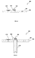
- FIG. 5 illustrates a perspective view of a pressure sense die attached to a mounting surface via soldering, which the mounting surface is then attached to an additional mounting surface which contains the ASIC and electronics, in accordance with a preferred embodiment
- FIG. 6 illustrates a perspective view of a collar, which can be implemented in accordance with an alternative embodiment.
- FIG. 1 illustrates a perspective view of a pressure sense die 100, in accordance with a preferred embodiment.
- the pressure sense die 100 includes a piezo-resistive element 110 and a constraint pedestal (e.g., glass, silicon, or other) 120.
- the constraint pedestal 120 provides isolation from stresses induced by the packaging or housing in which the pressure sense die 100 is mounted.
- the upper surface of the constraint pedestal 120 can be bonded, anodically or by other means, to the piezo-resistive element 110.
- the pressure sense die 100 normally comprises a pressure diaphragm 115, comprising one or more piezoresistors 125, which may be diffused into die (i.e., or applied by other means) 100 for providing a piezoresistive output signal related to the pressure sensed by the die 100.
- the piezo-resistive element 110 may be configured from a material such as, for example, silicon, polysilicon or glass, and can be utilized to measure a wide range of pressures.
- the constraint pedestal 120 possesses a metallized surface 130 that facilitates soldering to a mounting surface 140, which is not shown in FIG. 1 , but is depicted in FIG. 2 .
- FIG. 2 illustrates a perspective view of the pressure sense die 100 attached to the mounting surface 140 via soldering, in accordance with a preferred embodiment.
- the metallized surface 130 of the pressure sense die 100 can be soldered directly onto the mounting surface 140 associated with a substrate 150.
- the mounting surface 140 is suitably prepared for soldering and may possess a thermal coefficient of expansion substantially matching the thermal coefficient of expansion of the pressure sense die 100.
- the substrate 150 may be configured from a material such as, for example, FR4, ceramic, silicon, metal or glass, which provides stress isolation between the pressure sense die 100 and external components utilized for sensing pressure and the surrounding environment.
- the metallized surface 130 as depicted in FIG. 1 , facilitates soldering to the suitably prepared mounting surface 140 of the substrate.
- the soldering process can utilize, for example, paste, pre-form, or another suitable soldering method.
- FIG. 3 illustrates a perspective view of the pressure sense die 100, in accordance with a preferred embodiment.
- the solder joint 160 can be utilized to attach the substrate 150 to the pressure sense die 100.
- the solder joint 160 between the metalized surface 130 and the substrate 150 provides a hermetic seal that is resistant to a wide range of media associated with different environmental conditions.
- the solder joint 160 can constitute lead and tin.
- Other metals that can be utilized in the solder joint 160 include metals such as, for example, aluminum, cadmium, zinc, nickel, gold, silver, palladium, bismuth, copper, antimony, and so forth. It will be apparent to those skilled in the art, however, that other metals can be utilized without departing from the scope of the present invention discussed herein.
- solder joint 160 is, thus, very strong over a wide range of temperatures and pressures. Note that the embodiment depicted in FIG. 3 can be considered a sub-assembly 610 that is capable of being incorporated into higher-level assemblies containing amplification and temperature compensation properties.
- FIG. 4 illustrates a perspective view of a pressure sensor 400 associated with an ASIC 210, in accordance with a preferred embodiment.
- the pressure sensor 400 may include another means of external amplification and temperature compensation in place of the ASIC 210.
- the pressure sense die 100 and the ASIC 210 can be electrically connected together internally or externally.
- the ASIC 210 can be incorporated on the primary substrate 150 utilizing wire bonds 220.
- the ASIC 210 can be utilized in conjunction with the pressure sensor 400 to receive a sensor input signal and convert the input signal into an output signal utilized by a control system.
- the incorporation of the signal conditioning ASIC 210 provides the required amplification and temperature compensation necessary for silicon pressure sensors of this general type to measure gage pressure, absolute pressure or differential pressure.
- FIG. 5 illustrates a perspective view of a pressure sensor 600 associated with a sub-assembly 610, in accordance with a preferred embodiment.
- the sub-assembly 610 can be attached to the primary substrate 150.
- the primary substrate 150 mechanically supports and electrically connects the components of the pressure sensor 600.
- the mounting surface 140 of the substrate 150 includes the ASIC 210 and the wire bonds 220.
- the mounting surface 140 can contain the ASIC 210 and electronics for compensation or can be attached to another sub-assembly 610, which contains the ASIC and electronics.
- FIG. 6 illustrates a perspective view of a collar 800 associated with the sub-assembly 610, which can be utilized in accordance with an alternative embodiment.
- the ASIC compensated pressure sensor as depicted in FIG. 6 incorporates the pressure sense die 100, the ASIC 210, and support elements, such as, for example, collar 800, and sub-assembly 610, which an be bonded to the substrate 150.
- the resulting solder joint 160 between pressure sense die 100 and mounting surface 140 can provide for a hermetic seal that is resistant to a wide range of media in different environmental conditions.
- the mounting surface 140 may also be configured to possess a closely matched coefficient of thermal expansion with respect to the pressure sense die 100 in order to ensure the electrical stability of the output signal over a wide range of temperatures and pressures.
- the incorporation of the signal-conditioning ASIC 210 additionally provides the required accuracy to avoid the need for post die attachment laser trim operations.
- Such an ASIC compensated pressure sensor is capable of being constructed in several different design options for optimal assembly and environmental
Landscapes
- Physics & Mathematics (AREA)
- General Physics & Mathematics (AREA)
- Measuring Fluid Pressure (AREA)
Applications Claiming Priority (1)
| Application Number | Priority Date | Filing Date | Title |
|---|---|---|---|
| US12/120,378 US7930944B2 (en) | 2008-05-14 | 2008-05-14 | ASIC compensated pressure sensor with soldered sense die attach |
Publications (3)
| Publication Number | Publication Date |
|---|---|
| EP2120029A2 true EP2120029A2 (fr) | 2009-11-18 |
| EP2120029A3 EP2120029A3 (fr) | 2016-06-29 |
| EP2120029B1 EP2120029B1 (fr) | 2019-04-10 |
Family
ID=40941737
Family Applications (1)
| Application Number | Title | Priority Date | Filing Date |
|---|---|---|---|
| EP09159241.0A Not-in-force EP2120029B1 (fr) | 2008-05-14 | 2009-04-30 | Capteur de pression à compensation ASIC avec fixation du puce de détection par soudage |
Country Status (3)
| Country | Link |
|---|---|
| US (1) | US7930944B2 (fr) |
| EP (1) | EP2120029B1 (fr) |
| CN (1) | CN101581618A (fr) |
Cited By (1)
| Publication number | Priority date | Publication date | Assignee | Title |
|---|---|---|---|---|
| WO2018160362A1 (fr) | 2017-02-28 | 2018-09-07 | Rosemount Inc. | Joint pour corps fragiles |
Families Citing this family (11)
| Publication number | Priority date | Publication date | Assignee | Title |
|---|---|---|---|---|
| US8375799B2 (en) * | 2010-12-10 | 2013-02-19 | Honeywell International Inc. | Increased sensor die adhesion |
| US8371176B2 (en) | 2011-01-06 | 2013-02-12 | Honeywell International Inc. | Media isolated pressure sensor |
| US8297127B2 (en) | 2011-01-07 | 2012-10-30 | Honeywell International Inc. | Pressure sensor with low cost packaging |
| CN102445301A (zh) * | 2011-11-23 | 2012-05-09 | 无锡芯感智半导体有限公司 | 温漂自补偿soi压力传感器 |
| US8516897B1 (en) | 2012-02-21 | 2013-08-27 | Honeywell International Inc. | Pressure sensor |
| US9027410B2 (en) * | 2012-09-14 | 2015-05-12 | Sensata Technologies, Inc. | Hermetically glass sealed pressure sensor |
| US9410861B2 (en) | 2014-03-25 | 2016-08-09 | Honeywell International Inc. | Pressure sensor with overpressure protection |
| CN106461474B (zh) * | 2014-06-27 | 2019-04-30 | 北陆电气工业株式会社 | 力检测器 |
| US10203255B2 (en) * | 2016-08-25 | 2019-02-12 | Measurement Specialties, Inc. | Differential pressure sensor incorporating common mode error compensation |
| US10544040B2 (en) * | 2017-05-05 | 2020-01-28 | Dunan Microstaq, Inc. | Method and structure for preventing solder flow into a MEMS pressure port during MEMS die attachment |
| US10640374B2 (en) * | 2017-05-18 | 2020-05-05 | Dunan Microstaq, Inc. | Method and structure of attachment layer for reducing stress transmission to attached MEMS die |
Family Cites Families (39)
| Publication number | Priority date | Publication date | Assignee | Title |
|---|---|---|---|---|
| JPS5365089A (en) * | 1976-11-24 | 1978-06-10 | Toshiba Corp | Semiconductor pressure transducer |
| US4129042A (en) * | 1977-11-18 | 1978-12-12 | Signetics Corporation | Semiconductor transducer packaged assembly |
| JPS5524423A (en) * | 1978-08-10 | 1980-02-21 | Nissan Motor Co Ltd | Semiconductor pressure sensor |
| US4763098A (en) * | 1985-04-08 | 1988-08-09 | Honeywell Inc. | Flip-chip pressure transducer |
| US4656454A (en) * | 1985-04-24 | 1987-04-07 | Honeywell Inc. | Piezoresistive pressure transducer with elastomeric seals |
| US4939497A (en) * | 1989-04-18 | 1990-07-03 | Nippon Soken, Inc. | Pressure sensor |
| US5025667A (en) * | 1989-06-15 | 1991-06-25 | Texas Instruments Incorporated | Hermetic pressure sensor |
| JPH04155233A (ja) | 1990-10-18 | 1992-05-28 | Yamatake Honeywell Co Ltd | 圧力センサの温度特性の補正方法 |
| US5257457A (en) * | 1992-08-24 | 1993-11-02 | Cotter Joel M | Hand-held tree girdler |
| US5465626A (en) * | 1994-04-04 | 1995-11-14 | Motorola, Inc. | Pressure sensor with stress isolation platform hermetically sealed to protect sensor die |
| JPH0875581A (ja) | 1994-09-09 | 1996-03-22 | Yamatake Honeywell Co Ltd | 半導体圧力変換器 |
| US5811690A (en) * | 1997-03-20 | 1998-09-22 | Hershey; George E. | Differential pressure transmitter with highly accurate temperature compensation |
| JP3918301B2 (ja) | 1998-05-22 | 2007-05-23 | 松下電工株式会社 | 半導体圧力センサ |
| JP2000004667A (ja) | 1998-06-29 | 2000-01-11 | Showa Denko Kk | 緑化基盤材料およびその使用方法 |
| US6351996B1 (en) * | 1998-11-12 | 2002-03-05 | Maxim Integrated Products, Inc. | Hermetic packaging for semiconductor pressure sensors |
| JP3617346B2 (ja) | 1998-12-15 | 2005-02-02 | 松下電工株式会社 | 半導体圧力センサ |
| JP3449268B2 (ja) | 1998-12-21 | 2003-09-22 | 松下電工株式会社 | 半導体圧力センサ |
| DE19919112A1 (de) | 1999-04-27 | 2000-11-09 | Bosch Gmbh Robert | Vorrichtung und Verfahren zum Fügen von Drucksensoren |
| US20020029639A1 (en) * | 2000-01-19 | 2002-03-14 | Measurement Specialities, Inc. | Isolation technique for pressure sensing structure |
| JP2001208626A (ja) | 2000-01-24 | 2001-08-03 | Mitsubishi Electric Corp | 半導体圧力センサ装置 |
| EP1255099B1 (fr) | 2001-05-04 | 2007-07-04 | Trafag AG | Capteur de pression pour capter la pression dans la chambre de combustion d'un moteur et son procédé de fabrication |
| JP2003057138A (ja) | 2001-08-09 | 2003-02-26 | Matsushita Electric Works Ltd | 半導体圧力センサ |
| AU2003256855A1 (en) | 2002-08-05 | 2004-02-23 | Board Of Regents, The University Of Texas System | Porous burner for gas turbine applications |
| US6931938B2 (en) * | 2002-12-16 | 2005-08-23 | Jeffrey G. Knirck | Measuring pressure exerted by a rigid surface |
| US6868731B1 (en) * | 2003-11-20 | 2005-03-22 | Honeywell International, Inc. | Digital output MEMS pressure sensor and method |
| JP4155233B2 (ja) | 2004-06-24 | 2008-09-24 | 株式会社日立製作所 | 映像表示装置 |
| US6945120B1 (en) * | 2004-07-02 | 2005-09-20 | Honeywell International Inc. | Exhaust gas recirculation system using absolute micromachined pressure sense die |
| US7077008B2 (en) * | 2004-07-02 | 2006-07-18 | Honeywell International Inc. | Differential pressure measurement using backside sensing and a single ASIC |
| US7073375B2 (en) * | 2004-07-02 | 2006-07-11 | Honeywell International Inc. | Exhaust back pressure sensor using absolute micromachined pressure sense die |
| JP2006023115A (ja) | 2004-07-06 | 2006-01-26 | Surpass Kogyo Kk | 絶対圧形圧力センサの製造方法および製造装置 |
| DE102004063598A1 (de) | 2004-12-30 | 2006-07-13 | Trafag Ag | Drucksensor |
| DE102005027365A1 (de) * | 2005-06-14 | 2006-12-21 | Robert Bosch Gmbh | Hochdrucksensoreinrichtung und Verfahren zu ihrer Herstellung |
| US7635077B2 (en) * | 2005-09-27 | 2009-12-22 | Honeywell International Inc. | Method of flip chip mounting pressure sensor dies to substrates and pressure sensors formed thereby |
| US8010322B2 (en) * | 2006-05-17 | 2011-08-30 | Honeywell International Inc. | Signal conditioning IC with conditioning-coefficient memory |
| AT503816B1 (de) * | 2006-06-06 | 2008-01-15 | Piezocryst Advanced Sensorics | Piezoelektrischer sensor |
| US20080222884A1 (en) * | 2007-03-14 | 2008-09-18 | Honeywell International Inc. | Packaging for chip-on-board pressure sensor |
| US7759945B2 (en) * | 2007-08-22 | 2010-07-20 | Honeywell International Inc. | Sensor including dual range, application specific integrated chip (ASIC) |
| US7647835B2 (en) * | 2007-09-19 | 2010-01-19 | Honeywell International Inc. | Pressure sensor stress isolation pedestal |
| US7677109B2 (en) * | 2008-02-27 | 2010-03-16 | Honeywell International Inc. | Pressure sense die pad layout and method for direct wire bonding to programmable compensation integrated circuit die |
-
2008
- 2008-05-14 US US12/120,378 patent/US7930944B2/en active Active
-
2009
- 2009-04-30 EP EP09159241.0A patent/EP2120029B1/fr not_active Not-in-force
- 2009-05-13 CN CNA2009101409221A patent/CN101581618A/zh active Pending
Cited By (2)
| Publication number | Priority date | Publication date | Assignee | Title |
|---|---|---|---|---|
| WO2018160362A1 (fr) | 2017-02-28 | 2018-09-07 | Rosemount Inc. | Joint pour corps fragiles |
| EP3589442A4 (fr) * | 2017-02-28 | 2021-01-06 | Rosemount Inc. | Joint pour corps fragiles |
Also Published As
| Publication number | Publication date |
|---|---|
| US7930944B2 (en) | 2011-04-26 |
| CN101581618A (zh) | 2009-11-18 |
| EP2120029A3 (fr) | 2016-06-29 |
| EP2120029B1 (fr) | 2019-04-10 |
| US20090282925A1 (en) | 2009-11-19 |
Similar Documents
| Publication | Publication Date | Title |
|---|---|---|
| US7930944B2 (en) | ASIC compensated pressure sensor with soldered sense die attach | |
| EP2474819B1 (fr) | Capteur de pression isolé d'un milieu | |
| EP2273247A2 (fr) | Ensemble d'emballage de capteur de pression doté d'une puce de détection sans contraintes | |
| EP2189773B1 (fr) | Design de capteur de pression différentielle liquide/liquide basé sur un procédé de conditionnement microélectronique | |
| EP2474820B1 (fr) | Capteur de pression avec conditionnement à bas coût | |
| US8316725B2 (en) | Force sensor | |
| US7412894B2 (en) | Pressure sensing device incorporating pressure sensing chip in resin case | |
| EP2873960B1 (fr) | Capteur de mesure de quantité physique | |
| EP2316008B1 (fr) | Encapsulation de dispositif capteur et procédé correspondant | |
| US7377177B1 (en) | Pressure sensor method and apparatus | |
| US20030167851A1 (en) | Absolute micromachined silicon pressure sensor with backside hermetic cover and method of making the same | |
| US20080222884A1 (en) | Packaging for chip-on-board pressure sensor | |
| US20100180688A1 (en) | Media isolated pressure transducer having boss comprising single metal diaphragm | |
| CN105953970A (zh) | 具有多个传感器元件的封装的传感器 | |
| US10422710B2 (en) | Semiconductor differential pressure sensor | |
| US6907789B2 (en) | Sensor package | |
| EP3205998B1 (fr) | Capteur de pression à membrane ouverte pour milieu agressif | |
| US9506831B2 (en) | Micromechanical measuring element and method for producing a micromechanical measuring element | |
| US20180086626A1 (en) | Method of manufacturing a sensor | |
| EP1634046B1 (fr) | Capteur de pression a structure integree | |
| US11015994B2 (en) | Differential MEMS pressure sensors with a ceramic header body and methods of making differential MEMS pressure sensors | |
| JPH09138173A (ja) | 半導体圧力センサ | |
| EP2894450A1 (fr) | Capteur pour mesurer des variables de fluide dans un environnement corrosif | |
| JP2009075041A (ja) | 相対圧測定用圧力センサ |
Legal Events
| Date | Code | Title | Description |
|---|---|---|---|
| PUAI | Public reference made under article 153(3) epc to a published international application that has entered the european phase |
Free format text: ORIGINAL CODE: 0009012 |
|
| 17P | Request for examination filed |
Effective date: 20090430 |
|
| AK | Designated contracting states |
Kind code of ref document: A2 Designated state(s): AT BE BG CH CY CZ DE DK EE ES FI FR GB GR HR HU IE IS IT LI LT LU LV MC MK MT NL NO PL PT RO SE SI SK TR |
|
| RAP1 | Party data changed (applicant data changed or rights of an application transferred) |
Owner name: HONEYWELL INTERNATIONAL INC. |
|
| PUAL | Search report despatched |
Free format text: ORIGINAL CODE: 0009013 |
|
| AK | Designated contracting states |
Kind code of ref document: A3 Designated state(s): AT BE BG CH CY CZ DE DK EE ES FI FR GB GR HR HU IE IS IT LI LT LU LV MC MK MT NL NO PL PT RO SE SI SK TR |
|
| AX | Request for extension of the european patent |
Extension state: AL BA RS |
|
| RIC1 | Information provided on ipc code assigned before grant |
Ipc: G01L 9/06 20060101AFI20160520BHEP |
|
| 17Q | First examination report despatched |
Effective date: 20160706 |
|
| STAA | Information on the status of an ep patent application or granted ep patent |
Free format text: STATUS: EXAMINATION IS IN PROGRESS |
|
| GRAP | Despatch of communication of intention to grant a patent |
Free format text: ORIGINAL CODE: EPIDOSNIGR1 |
|
| STAA | Information on the status of an ep patent application or granted ep patent |
Free format text: STATUS: GRANT OF PATENT IS INTENDED |
|
| INTG | Intention to grant announced |
Effective date: 20181120 |
|
| GRAS | Grant fee paid |
Free format text: ORIGINAL CODE: EPIDOSNIGR3 |
|
| GRAA | (expected) grant |
Free format text: ORIGINAL CODE: 0009210 |
|
| STAA | Information on the status of an ep patent application or granted ep patent |
Free format text: STATUS: THE PATENT HAS BEEN GRANTED |
|
| AK | Designated contracting states |
Kind code of ref document: B1 Designated state(s): AT BE BG CH CY CZ DE DK EE ES FI FR GB GR HR HU IE IS IT LI LT LU LV MC MK MT NL NO PL PT RO SE SI SK TR |
|
| REG | Reference to a national code |
Ref country code: GB Ref legal event code: FG4D |
|
| REG | Reference to a national code |
Ref country code: CH Ref legal event code: EP Ref country code: AT Ref legal event code: REF Ref document number: 1119351 Country of ref document: AT Kind code of ref document: T Effective date: 20190415 |
|
| REG | Reference to a national code |
Ref country code: DE Ref legal event code: R096 Ref document number: 602009057798 Country of ref document: DE |
|
| REG | Reference to a national code |
Ref country code: IE Ref legal event code: FG4D |
|
| REG | Reference to a national code |
Ref country code: NL Ref legal event code: MP Effective date: 20190410 |
|
| REG | Reference to a national code |
Ref country code: LT Ref legal event code: MG4D |
|
| REG | Reference to a national code |
Ref country code: AT Ref legal event code: MK05 Ref document number: 1119351 Country of ref document: AT Kind code of ref document: T Effective date: 20190410 |
|
| PG25 | Lapsed in a contracting state [announced via postgrant information from national office to epo] |
Ref country code: NL Free format text: LAPSE BECAUSE OF FAILURE TO SUBMIT A TRANSLATION OF THE DESCRIPTION OR TO PAY THE FEE WITHIN THE PRESCRIBED TIME-LIMIT Effective date: 20190410 |
|
| PG25 | Lapsed in a contracting state [announced via postgrant information from national office to epo] |
Ref country code: SE Free format text: LAPSE BECAUSE OF FAILURE TO SUBMIT A TRANSLATION OF THE DESCRIPTION OR TO PAY THE FEE WITHIN THE PRESCRIBED TIME-LIMIT Effective date: 20190410 Ref country code: LT Free format text: LAPSE BECAUSE OF FAILURE TO SUBMIT A TRANSLATION OF THE DESCRIPTION OR TO PAY THE FEE WITHIN THE PRESCRIBED TIME-LIMIT Effective date: 20190410 Ref country code: HR Free format text: LAPSE BECAUSE OF FAILURE TO SUBMIT A TRANSLATION OF THE DESCRIPTION OR TO PAY THE FEE WITHIN THE PRESCRIBED TIME-LIMIT Effective date: 20190410 Ref country code: ES Free format text: LAPSE BECAUSE OF FAILURE TO SUBMIT A TRANSLATION OF THE DESCRIPTION OR TO PAY THE FEE WITHIN THE PRESCRIBED TIME-LIMIT Effective date: 20190410 Ref country code: FI Free format text: LAPSE BECAUSE OF FAILURE TO SUBMIT A TRANSLATION OF THE DESCRIPTION OR TO PAY THE FEE WITHIN THE PRESCRIBED TIME-LIMIT Effective date: 20190410 Ref country code: NO Free format text: LAPSE BECAUSE OF FAILURE TO SUBMIT A TRANSLATION OF THE DESCRIPTION OR TO PAY THE FEE WITHIN THE PRESCRIBED TIME-LIMIT Effective date: 20190710 Ref country code: PT Free format text: LAPSE BECAUSE OF FAILURE TO SUBMIT A TRANSLATION OF THE DESCRIPTION OR TO PAY THE FEE WITHIN THE PRESCRIBED TIME-LIMIT Effective date: 20190910 |
|
| PG25 | Lapsed in a contracting state [announced via postgrant information from national office to epo] |
Ref country code: GR Free format text: LAPSE BECAUSE OF FAILURE TO SUBMIT A TRANSLATION OF THE DESCRIPTION OR TO PAY THE FEE WITHIN THE PRESCRIBED TIME-LIMIT Effective date: 20190711 Ref country code: PL Free format text: LAPSE BECAUSE OF FAILURE TO SUBMIT A TRANSLATION OF THE DESCRIPTION OR TO PAY THE FEE WITHIN THE PRESCRIBED TIME-LIMIT Effective date: 20190410 Ref country code: BG Free format text: LAPSE BECAUSE OF FAILURE TO SUBMIT A TRANSLATION OF THE DESCRIPTION OR TO PAY THE FEE WITHIN THE PRESCRIBED TIME-LIMIT Effective date: 20190710 Ref country code: LV Free format text: LAPSE BECAUSE OF FAILURE TO SUBMIT A TRANSLATION OF THE DESCRIPTION OR TO PAY THE FEE WITHIN THE PRESCRIBED TIME-LIMIT Effective date: 20190410 |
|
| REG | Reference to a national code |
Ref country code: CH Ref legal event code: PL |
|
| REG | Reference to a national code |
Ref country code: BE Ref legal event code: MM Effective date: 20190430 |
|
| PG25 | Lapsed in a contracting state [announced via postgrant information from national office to epo] |
Ref country code: LU Free format text: LAPSE BECAUSE OF NON-PAYMENT OF DUE FEES Effective date: 20190430 Ref country code: IS Free format text: LAPSE BECAUSE OF FAILURE TO SUBMIT A TRANSLATION OF THE DESCRIPTION OR TO PAY THE FEE WITHIN THE PRESCRIBED TIME-LIMIT Effective date: 20190810 Ref country code: AT Free format text: LAPSE BECAUSE OF FAILURE TO SUBMIT A TRANSLATION OF THE DESCRIPTION OR TO PAY THE FEE WITHIN THE PRESCRIBED TIME-LIMIT Effective date: 20190410 |
|
| REG | Reference to a national code |
Ref country code: DE Ref legal event code: R097 Ref document number: 602009057798 Country of ref document: DE |
|
| PG25 | Lapsed in a contracting state [announced via postgrant information from national office to epo] |
Ref country code: DK Free format text: LAPSE BECAUSE OF FAILURE TO SUBMIT A TRANSLATION OF THE DESCRIPTION OR TO PAY THE FEE WITHIN THE PRESCRIBED TIME-LIMIT Effective date: 20190410 Ref country code: LI Free format text: LAPSE BECAUSE OF NON-PAYMENT OF DUE FEES Effective date: 20190430 Ref country code: SK Free format text: LAPSE BECAUSE OF FAILURE TO SUBMIT A TRANSLATION OF THE DESCRIPTION OR TO PAY THE FEE WITHIN THE PRESCRIBED TIME-LIMIT Effective date: 20190410 Ref country code: MC Free format text: LAPSE BECAUSE OF FAILURE TO SUBMIT A TRANSLATION OF THE DESCRIPTION OR TO PAY THE FEE WITHIN THE PRESCRIBED TIME-LIMIT Effective date: 20190410 Ref country code: CZ Free format text: LAPSE BECAUSE OF FAILURE TO SUBMIT A TRANSLATION OF THE DESCRIPTION OR TO PAY THE FEE WITHIN THE PRESCRIBED TIME-LIMIT Effective date: 20190410 Ref country code: RO Free format text: LAPSE BECAUSE OF FAILURE TO SUBMIT A TRANSLATION OF THE DESCRIPTION OR TO PAY THE FEE WITHIN THE PRESCRIBED TIME-LIMIT Effective date: 20190410 Ref country code: CH Free format text: LAPSE BECAUSE OF NON-PAYMENT OF DUE FEES Effective date: 20190430 Ref country code: EE Free format text: LAPSE BECAUSE OF FAILURE TO SUBMIT A TRANSLATION OF THE DESCRIPTION OR TO PAY THE FEE WITHIN THE PRESCRIBED TIME-LIMIT Effective date: 20190410 |
|
| PLBE | No opposition filed within time limit |
Free format text: ORIGINAL CODE: 0009261 |
|
| STAA | Information on the status of an ep patent application or granted ep patent |
Free format text: STATUS: NO OPPOSITION FILED WITHIN TIME LIMIT |
|
| PG25 | Lapsed in a contracting state [announced via postgrant information from national office to epo] |
Ref country code: IT Free format text: LAPSE BECAUSE OF FAILURE TO SUBMIT A TRANSLATION OF THE DESCRIPTION OR TO PAY THE FEE WITHIN THE PRESCRIBED TIME-LIMIT Effective date: 20190410 Ref country code: BE Free format text: LAPSE BECAUSE OF NON-PAYMENT OF DUE FEES Effective date: 20190430 |
|
| 26N | No opposition filed |
Effective date: 20200113 |
|
| PG25 | Lapsed in a contracting state [announced via postgrant information from national office to epo] |
Ref country code: TR Free format text: LAPSE BECAUSE OF FAILURE TO SUBMIT A TRANSLATION OF THE DESCRIPTION OR TO PAY THE FEE WITHIN THE PRESCRIBED TIME-LIMIT Effective date: 20190410 |
|
| PG25 | Lapsed in a contracting state [announced via postgrant information from national office to epo] |
Ref country code: IE Free format text: LAPSE BECAUSE OF NON-PAYMENT OF DUE FEES Effective date: 20190430 |
|
| PG25 | Lapsed in a contracting state [announced via postgrant information from national office to epo] |
Ref country code: SI Free format text: LAPSE BECAUSE OF FAILURE TO SUBMIT A TRANSLATION OF THE DESCRIPTION OR TO PAY THE FEE WITHIN THE PRESCRIBED TIME-LIMIT Effective date: 20190410 |
|
| PG25 | Lapsed in a contracting state [announced via postgrant information from national office to epo] |
Ref country code: CY Free format text: LAPSE BECAUSE OF FAILURE TO SUBMIT A TRANSLATION OF THE DESCRIPTION OR TO PAY THE FEE WITHIN THE PRESCRIBED TIME-LIMIT Effective date: 20190410 |
|
| PG25 | Lapsed in a contracting state [announced via postgrant information from national office to epo] |
Ref country code: HU Free format text: LAPSE BECAUSE OF FAILURE TO SUBMIT A TRANSLATION OF THE DESCRIPTION OR TO PAY THE FEE WITHIN THE PRESCRIBED TIME-LIMIT; INVALID AB INITIO Effective date: 20090430 Ref country code: MT Free format text: LAPSE BECAUSE OF FAILURE TO SUBMIT A TRANSLATION OF THE DESCRIPTION OR TO PAY THE FEE WITHIN THE PRESCRIBED TIME-LIMIT Effective date: 20190410 |
|
| PG25 | Lapsed in a contracting state [announced via postgrant information from national office to epo] |
Ref country code: MK Free format text: LAPSE BECAUSE OF FAILURE TO SUBMIT A TRANSLATION OF THE DESCRIPTION OR TO PAY THE FEE WITHIN THE PRESCRIBED TIME-LIMIT Effective date: 20190410 |
|
| PGFP | Annual fee paid to national office [announced via postgrant information from national office to epo] |
Ref country code: GB Payment date: 20220419 Year of fee payment: 14 Ref country code: FR Payment date: 20220427 Year of fee payment: 14 Ref country code: DE Payment date: 20220428 Year of fee payment: 14 |
|
| REG | Reference to a national code |
Ref country code: DE Ref legal event code: R119 Ref document number: 602009057798 Country of ref document: DE |
|
| GBPC | Gb: european patent ceased through non-payment of renewal fee |
Effective date: 20230430 |
|
| PG25 | Lapsed in a contracting state [announced via postgrant information from national office to epo] |
Ref country code: GB Free format text: LAPSE BECAUSE OF NON-PAYMENT OF DUE FEES Effective date: 20230430 |
|
| PG25 | Lapsed in a contracting state [announced via postgrant information from national office to epo] |
Ref country code: GB Free format text: LAPSE BECAUSE OF NON-PAYMENT OF DUE FEES Effective date: 20230430 Ref country code: FR Free format text: LAPSE BECAUSE OF NON-PAYMENT OF DUE FEES Effective date: 20230430 Ref country code: DE Free format text: LAPSE BECAUSE OF NON-PAYMENT OF DUE FEES Effective date: 20231103 |