EP2119527A1 - Procédé et système pour la fabrication de plaques d'impression en creux pour la production de papiers sécurisés - Google Patents
Procédé et système pour la fabrication de plaques d'impression en creux pour la production de papiers sécurisés Download PDFInfo
- Publication number
- EP2119527A1 EP2119527A1 EP08156392A EP08156392A EP2119527A1 EP 2119527 A1 EP2119527 A1 EP 2119527A1 EP 08156392 A EP08156392 A EP 08156392A EP 08156392 A EP08156392 A EP 08156392A EP 2119527 A1 EP2119527 A1 EP 2119527A1
- Authority
- EP
- European Patent Office
- Prior art keywords
- engraving
- printing plate
- plate medium
- laser
- engraved
- Prior art date
- Legal status (The legal status is an assumption and is not a legal conclusion. Google has not performed a legal analysis and makes no representation as to the accuracy of the status listed.)
- Withdrawn
Links
Images


Classifications
-
- B—PERFORMING OPERATIONS; TRANSPORTING
- B41—PRINTING; LINING MACHINES; TYPEWRITERS; STAMPS
- B41N—PRINTING PLATES OR FOILS; MATERIALS FOR SURFACES USED IN PRINTING MACHINES FOR PRINTING, INKING, DAMPING, OR THE LIKE; PREPARING SUCH SURFACES FOR USE AND CONSERVING THEM
- B41N3/00—Preparing for use and conserving printing surfaces
- B41N3/003—Preparing for use and conserving printing surfaces of intaglio formes, e.g. application of a wear-resistant coating, such as chrome, on the already-engraved plate or cylinder; Preparing for reuse, e.g. removing of the Ballard shell; Correction of the engraving
-
- B—PERFORMING OPERATIONS; TRANSPORTING
- B23—MACHINE TOOLS; METAL-WORKING NOT OTHERWISE PROVIDED FOR
- B23K—SOLDERING OR UNSOLDERING; WELDING; CLADDING OR PLATING BY SOLDERING OR WELDING; CUTTING BY APPLYING HEAT LOCALLY, e.g. FLAME CUTTING; WORKING BY LASER BEAM
- B23K26/00—Working by laser beam, e.g. welding, cutting or boring
- B23K26/70—Auxiliary operations or equipment
- B23K26/702—Auxiliary equipment
-
- B—PERFORMING OPERATIONS; TRANSPORTING
- B41—PRINTING; LINING MACHINES; TYPEWRITERS; STAMPS
- B41C—PROCESSES FOR THE MANUFACTURE OR REPRODUCTION OF PRINTING SURFACES
- B41C1/00—Forme preparation
- B41C1/02—Engraving; Heads therefor
- B41C1/04—Engraving; Heads therefor using heads controlled by an electric information signal
- B41C1/05—Heat-generating engraving heads, e.g. laser beam, electron beam
-
- B—PERFORMING OPERATIONS; TRANSPORTING
- B41—PRINTING; LINING MACHINES; TYPEWRITERS; STAMPS
- B41C—PROCESSES FOR THE MANUFACTURE OR REPRODUCTION OF PRINTING SURFACES
- B41C1/00—Forme preparation
- B41C1/10—Forme preparation for lithographic printing; Master sheets for transferring a lithographic image to the forme
- B41C1/1008—Forme preparation for lithographic printing; Master sheets for transferring a lithographic image to the forme by removal or destruction of lithographic material on the lithographic support, e.g. by laser or spark ablation; by the use of materials rendered soluble or insoluble by heat exposure, e.g. by heat produced from a light to heat transforming system; by on-the-press exposure or on-the-press development, e.g. by the fountain of photolithographic materials
-
- B—PERFORMING OPERATIONS; TRANSPORTING
- B41—PRINTING; LINING MACHINES; TYPEWRITERS; STAMPS
- B41N—PRINTING PLATES OR FOILS; MATERIALS FOR SURFACES USED IN PRINTING MACHINES FOR PRINTING, INKING, DAMPING, OR THE LIKE; PREPARING SUCH SURFACES FOR USE AND CONSERVING THEM
- B41N3/00—Preparing for use and conserving printing surfaces
- B41N3/03—Chemical or electrical pretreatment
-
- B—PERFORMING OPERATIONS; TRANSPORTING
- B41—PRINTING; LINING MACHINES; TYPEWRITERS; STAMPS
- B41C—PROCESSES FOR THE MANUFACTURE OR REPRODUCTION OF PRINTING SURFACES
- B41C2210/00—Preparation or type or constituents of the imaging layers, in relation to lithographic printing forme preparation
- B41C2210/04—Negative working, i.e. the non-exposed (non-imaged) areas are removed
-
- B—PERFORMING OPERATIONS; TRANSPORTING
- B41—PRINTING; LINING MACHINES; TYPEWRITERS; STAMPS
- B41M—PRINTING, DUPLICATING, MARKING, OR COPYING PROCESSES; COLOUR PRINTING
- B41M1/00—Inking and printing with a printer's forme
- B41M1/10—Intaglio printing ; Gravure printing
-
- B—PERFORMING OPERATIONS; TRANSPORTING
- B41—PRINTING; LINING MACHINES; TYPEWRITERS; STAMPS
- B41M—PRINTING, DUPLICATING, MARKING, OR COPYING PROCESSES; COLOUR PRINTING
- B41M3/00—Printing processes to produce particular kinds of printed work, e.g. patterns
- B41M3/14—Security printing
-
- B—PERFORMING OPERATIONS; TRANSPORTING
- B41—PRINTING; LINING MACHINES; TYPEWRITERS; STAMPS
- B41N—PRINTING PLATES OR FOILS; MATERIALS FOR SURFACES USED IN PRINTING MACHINES FOR PRINTING, INKING, DAMPING, OR THE LIKE; PREPARING SUCH SURFACES FOR USE AND CONSERVING THEM
- B41N1/00—Printing plates or foils; Materials therefor
- B41N1/04—Printing plates or foils; Materials therefor metallic
- B41N1/06—Printing plates or foils; Materials therefor metallic for relief printing or intaglio printing
Definitions
- the present invention generally relates to the field of intaglio printing as applied for the production of security papers, including banknotes, duty stamps, banderols or labels, identification or travel documents, etc.
- the present invention more precisely relates to a method and system for manufacturing intaglio printing plates for intaglio printing of sheets or webs of security papers, which method and system are based on the direct laser engraving of a printing plate medium, especially a metallic printing plate medium.
- European patent application No. EP 1 334 822 A2 discloses a method and installation for the direct laser engraving of intaglio printing plates or cylinders wherein engraving is performed by means of a laser beam generated by a pulsed Nd-YAG laser device.
- a laser-engravable printing plate medium is mounted onto a motor-driven platform capable of moving along two Cartesian axes and which is controlled by a computer, which computer also controls operation and actuation of the pulsed laser device.
- the pulsed laser device is mounted so as to be vertically movable and the height thereof with respect to the platform is adjustable by means of a motor controlled by the computer so as to correct and adjust focusing of the laser beam onto the plate to be engraved.
- An optical system with galvanometric motors is used to guide the laser beam on a focal lens that concentrates the laser beam on a desired point within a determined engraving area that covers only a limited part of the whole printing plate surface.
- the pulsed laser device is specifically designed to generate pulses whose power is largely higher than the power of ordinary continuously-operated laser devices.
- One disadvantage of this solution resides in the fact that the engraving process involves a repetitive local processing to engrave the whole area of the printing plate, an engraving area of the order of 100 mm x 100 mm being treated at a time.
- An optical system with appropriate focal length is provided to process each desired location within the engraving area.
- the angle of incidence of the laser beam with respect to the surface of the printing plate thus varies according to the position of the laser beam with respect to the locations of the engraving area being engraved, thereby potentially affecting engraving uniformity.
- Such processing moreover requires a very high accuracy so that no overlaps or gaps appear between adjacent engraving areas.
- the engraving area of this other system is of about 70 mm x 70 mm, which implies that only a limited part of the intaglio design might be engraved at a time and that the engraving process must be repeated with high accuracy so that no visible overlaps or gaps are formed between adjacent engraving areas. As disclosed in International application No. WO 2006/045128 A1 , this implies performing a calibration operation at regular intervals which is cumbersome and time-consuming.
- the printing plate which is made of or has an outer layer consisting of brass or an alloy thereof, is engraved directly by laser and, once fully engraved, is subjected to a cleaning process to remove the melted residues of the laser engraving process, which cleaning process involves a chemical treatment in a chemical bath of acidic solution, before being ultimately polished and chromed.
- a dry-ice pre-cleaning of the surface of the engraved printing plate by spraying of solid carbon-dioxide pellets may be performed prior to the chemical treatment of the engraved plate (see again Deinhammer2006).
- the proposed chemical post-engraving treatment of the engraved printing plate, as well as the dry-ice pre-cleaning, is rather aggressive and can lead to a degradation of the desired intaglio engravings if it is not controlled and carried out properly.
- the post-engraving processing with dry-ice pre-cleaning and treatment with acidic solution are furthermore prejudicial as they could lead to engraving non-uniformities and lack of repeatability, namely differences between two intaglio printing plates produced from a same design.
- a laser engraving device is then controlled based on this depth-map to perform a series of successive elementary engraving steps corresponding to each pixel of the depth-map.
- a typical resolution of engraving can be as high as 8000 dpi, which amounts to a distance between two successive elementary engraving steps of approximately 3 microns.
- a printing plate can be thus engraved by a laser beam based on the generated depth-map to produce engravings into the printing plate surface.
- a substantial advantage of this approach resides in the fact that the various design elements forming the whole intaglio design to be engraved in the printing plate are not engraved individually, but rather all at once pixel by pixel. Furthermore, and in contrast to the above-mentioned approaches, the engraving times are independent of the complexity of the intaglio design and depend only on the maximum depth of the design to be engraved. This pixel by pixel approach further translates into greater flexibility and control regarding the engraving profile and the shape thereof.
- the engraving method disclosed in International application No. WO 03/103962 A1 can in particular be put into practice to engrave highly complex intaglio patterns such as disclosed in International applications Nos. WO 2005/090090 A1 and WO 2007/119203 A1 , also in the name of the present Applicant.
- the pixel-by-pixel engraving principle disclosed in WO 03/103962 A1 is particularly suitable to engrave the patterns discussed in International application No. WO 2007/119203 A1 which exhibit a high complexity and density of elements, and this with reasonably low engraving times.
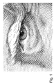
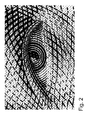
- Illustrative intaglio patterns are shown in Figures 1 and 2 , which intaglio patterns are analogous to those found on most intaglio-printed banknotes.
- Figure 1 is an enlarged view of an eye portion of a portrait that can be found in International application No. WO 03/103962 A1
- Figure 2 is an enlarged view of an eye portion of another portrait according to the teaching of International application No. WO 2007/119203 A1 wherein typical curvilinear intaglio patterns are interlaced with micro-letters that are dimensionally modulated to produce variations in tones.
- These intaglio patterns are typically formed of a complex arrangement of dimensionally modulated curvilinear elements that produce the desired halftones of the pictorial representation that one wishes to create on the security paper.
- the curvilinear elements typically have a line width of the order of 10 microns and more.
- the pixel-by-pixel engraving method can either be put into practice to engrave a precursor of an intaglio printing plate, such as a polymer plate, which precursor is then used to produce any number of identical printing plates by a galvanic replication process, or to directly engrave a metallic plate that is ultimately used as the intaglio printing plate, typically after chroming of the surface thereof.
- the engraving process is carried out by mounting the laser-engravable printing medium on the circumference of a rotating cylinder and moving the laser engraving device in a direction parallel to the axis of the cylinder.
- the laser engraving of polymer precursors of intaglio printing plates is advantageous over the direct laser engraving of printing plates in that engraving of a polymer precursor can be performed in a single pass and with a high engraving quality. Engraving of polymer precursors is accordingly particularly suited to the manufacture of high quality, high resolution intaglio printing plates for the production of banknotes.
- Direct laser engraving of intaglio printing plates however has an advantage in terms of environmental requirements in that it enables to circumvent the galvanic process which makes use of environmentally unfriendly chemical agents.
- a general aim of the invention is therefore to provide an improved method and system for manufacturing intaglio printing plates for the production of security papers, wherein a laser beam is used to engrave intaglio patterns directly into the surface of a laser-engravable printing plate medium
- a further aim of the invention is to provide such a method and system that improve the ability to shape the engraving profile of the intaglio patterns that one desires to engrave directly into the printing plate surface.
- Still another aim of the invention is to provide such a method and system that enables to limit the formation of melted residues and facilitates the removal and cleaning thereof, while guaranteeing a high quality of engraving.
- Yet another aim of the invention is to provide a solution that enables as much as possible to avoid resorting to the use of aggressive cleaning processes to remove the melted residues of the laser engraving process from the surface of the printing plate, which aggressive cleaning processes could negatively affect engraving uniformity and quality.
- a method for manufacturing intaglio printing plates for the production of security papers wherein a laser beam is used to engrave intaglio patterns directly into the surface of a laser-engravable, especially metallic, printing plate medium, wherein laser engraving of the printing plate medium is carried out in several individual engraving steps performed one after the other in register so that said intaglio patterns are gradually engraved into the surface of the printing plate medium up to desired engraving depths, the surface of the engraved printing plate medium being cleaned from residues of the laser engraving process following each individual engraving step.
- a direct laser engraving system for carrying out the above method, namely a laser engraving system comprising a support element for mounting the laser-engravable printing plate medium, a laser engraving unit producing a laser beam that is directed towards the surface of the printing plate medium for engraving the surface of the printing plate medium in several individual engraving steps and a cleaning unit for cleaning the surface of the engraved printing plate medium and removing residues therefrom following each individual engraving step.
- the engraving process is subdivided into a plurality of individual engraving steps which each involve removal of a limited quantity of material from the printing plate medium and accordingly limit the formation of residues. Furthermore, the surface of the engraved printing plate medium is cleaned following each individual engraving step such that the residues are removed before the next engraving step is performed, which ultimately improves engraving quality.
- each individual engraving step results in a selective removal of a layer of material from the printing plate medium the thickness of which does not exceed a pre-selected maximum value.
- This pre-selected maximum value is preferably of between 10 to 15 microns.
- cleaning of the surface of the engraved printing plate medium following each individual engraving step is performed mechanically, advantageously by means of a rotating brush that is moved over the surface of the engraved printing plate medium following each individual engraving step
- the printing plate medium is mounted onto the circumference of a support cylinder which is rotated in front of a movable laser engraving unit producing a laser beam that is directed towards the surface of the printing plate medium, which laser engraving unit is movable parallel to the axis of rotation of the support cylinder.
- the angle of incidence of the laser beam with respect to the surface of the printing plate medium being engraved is kept constant, thereby guaranteeing perfect engraving uniformity throughout the engraving process.
- a laser engraving unit producing a laser beam that is directed towards the surface of the printing plate medium is moved during each individual engraving step from a start position to an end position over the surface of the printing plate medium, and cleaning of the surface of the engraved printing plate medium is performed while the laser engraving unit, which is inoperative, is moved back from the end position to the start position.
- the laser engraving unit is moved during each individual engraving step from a start position to an end position step by step along the axis of rotation of the support cylinder so as to process successive annular portions of the surface of the printing plate medium, and cleaning of the surface of the engraved printing plate medium is performed while the laser engraving unit, which is inoperative, is moved back from the end position to the start position.
- engraving of the surface of the printing plate medium is first performed by starting with the deepest intaglio patterns and gradually adding shallower intaglio patterns during subsequent engraving steps.
- This advantageously enables to preserve the shallower and finer intaglio patterns up to the final engraving steps, which shallower and finer intaglio patterns are more sensitive to the cleaning operations.
- intaglio designs or “intaglio patterns” shall be understood as referring to designs and patterns produced by engraving and which consist of an arrangement of multiple curvilinear elements of varying line width and engraving depth.
- Such intaglio designs and patterns produce characterizing patterns on the printed product which are readily recognizable and are found on most security papers. Examples of such intaglio designs and patterns are illustrated in Figures 1 and 2 , which have already been discussed, as well as in Figure 3 which is illustrative of an exemplary intaglio design that can be produced by direct laser engraving according to the invention. These illustrations are obviously purely illustrative and shall not be considered as limiting the scope of the present invention.
- Intaglio designs and patterns produced according to the invention shall be distinguished from the designs and patterns used in the context of gravure printing (or rotogravure) where these merely consist of arrays of multiple cells of varying width and/or depth that are engraved into the surface of a cylinder , which cells are separated by cell walls.
- Gravure printing makes use of low viscosity inks that are allowed to flood above the cell walls so that the individual cells are no longer visible in the impression.
- the cells in gravure printing can typically be up to 50 microns deep (the cell depth being generally between 10 to 30 microns) and gravure printing does not produce any noticeable relief on the printed end-product.
- intaglio printing is based on the use of engraved printing plates having intaglio patterns taking the shape of curvilinear patterns the depth of at least part of which typically exceeds 50 microns.
- These intaglio patterns are furthermore inked with high viscosity inks and printing is carried out under high printing pressures, resulting in a characteristic embossing on the printed end-product.
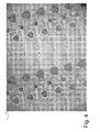
- FIG 3 illustrates an exemplary intaglio design, designated globally by reference numeral 12, of a duty stamp or banderol that can be produced by direct laser engraving according to the invention.
- This intaglio design 12 consists of multiple design elements 12a to 12g, including for instance a so-called latent image 12a, texts or like alphanumerical indications in varying sizes 12b, 12c, 12d, large surface patterns 12e with ink retaining structures (not illustrated), logos 12f, and guilloche patterns 12g. Any other patterns or combination thereof could be envisaged, including patterns similar to those found in typical intaglio portraits as depicted in Figures 1 and 2 .
- the various design elements 12a to 12g of the intaglio pattern of Figure 3 might be produced by suitable design software, such as the software ONE® marketed by the present Applicant.
- the engraving profile of each design element 12a to 12g might be defined individually according to parameters selected by the designer to create a so-called original depth-map as discussed in International application No. WO 03/103962 A1 .
- This original depth-map is then replicated digitally as many time as required to form a master depth-map of the intaglio printing plate to engrave.
- a partial view of the surface of an intaglio printing plate 1 engraved with the intaglio design of Figure 3 is shown in the greyscale photograph of Figure 4 .
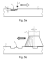
- Figure 5a schematically illustrates a printing plate medium 1 in the process of being engraved by a laser beam 2 to form engravings 3 in the surface thereof.
- the hatched area in Figure 5a is indicative of the material that is being removed by the laser beam 2.
- the dimensions of the engravings 3 have been exaggerated for the purpose of illustration.
- at least part of the intaglio patterns 3 can be engraved to a depth of approximately 80 microns. It shall be understood that the depth of the engravings can be as high as 150 (or eventually more), while a typical line width ranges from approximately 10 to 500 microns.
- Engraving is preferably performed pixel-by-pixel based on three-dimensional pixel data of an engraving depth-map of the desired intaglio patterns as discussed in International application No. WO 03/103962 A1 .
- the printing plate medium 1 is preferably made of or comprises an outer layer made of a metal such as nickel, steel, brass, zinc, chrome or alloys thereof, which materials are all commonly used in the art.
- the printing plate medium 1 is engraved in several individual engraving steps ( Figure 5a illustrate a first one of a series of individual engraving steps) performed one after the other in register so that the intaglio patterns are gradually engraved into the surface of the printing plate medium 1 up to desired engraving depths.
- each individual engraving step results in a selective removal of a layer of material from the printing plate medium 1 the thickness of which does not exceed a pre-selected maximum value ⁇ MAX .
- This maximum value ⁇ MAX is preferably of between 10 to 15 microns.
- the surface of the engraved printing plate medium 1 is cleaned following each individual engraving step. Cleaning of the surface of the printing plate medium 1 can conveniently be performed mechanically (i.e. without resorting to the use of aggressive cleaning processes). Such cleaning can advantageously be performed by means of a rotating brush 9 that is moved over the surface of the engraved printing plate medium 1.
- the printing plate medium 1 can advantageously be mounted onto the circumference of a support cylinder which is rotated in front of a movable laser engraving unit producing a laser beam that is directed towards the surface of the printing plate medium 1, which laser engraving unit is movable parallel to the axis of rotation of the support cylinder.
- each individual engraving step can conveniently be performed while the laser engraving unit is moved from a start position to an end position step by step along the axis of the support cylinder so as to process successive annular portions of the surface of the printing plate medium and cleaning of the surface of the printing plate medium 1 can be performed while the laser engraving unit, which is inoperative, is moved back from the end position to the start position.
- the angle of incidence of the laser beam 2 with respect to the surface of the printing plate medium 1 being engraved is kept constant, thereby guaranteeing perfect engraving uniformity throughout the engraving process.
- Figure 6 illustrates a possible sequence wherein first and second intaglio patterns, respectively designated by reference numerals 3.1 and 3.2 are gradually formed.
- a first intaglio pattern 3.1 is for instance engraved in three steps by forming a first partial engraving during a first engraving step, deepening the engraving to a second partial engraving during a second engraving step, and ultimately to the final intaglio pattern 3.1 during a third engraving step.
- a shallower intaglio pattern 3.2 is similarly engraved in two steps which are performed simultaneously with the first and second partial engravings of the first intaglio pattern 3.1, a partial engraving being engraved during the first step and subsequently deepened to the final intaglio pattern 3.2 during the second engraving step.
- the hatched areas in Figure 6 are again illustrative of the material that is being removed by the laser beam 2 during each engraving step (the same applies to Figure 7 and Figures 8a and 8b which are discussed hereinafter). It shall furthermore be understood that the surface of the printing plate medium 1 is cleaned from residues following each individual engraving step.
- Figure 7 illustrates another possible sequence wherein engraving of the surface of the printing plate medium 1 is first performed by starting with the deepest intaglio patterns, e.g. intaglio pattern 3.1, and gradually adding shallower intaglio patterns, e.g. intaglio pattern 3.2 followed by intaglio pattern 3.3, during subsequent engraving steps.
- the deepest intaglio patterns e.g. intaglio pattern 3.1
- shallower intaglio patterns e.g. intaglio pattern 3.2 followed by intaglio pattern 3.3
- focusing of the laser beam 2 needs to be adjusted in this case during the second and third engraving steps as material is removed at different levels of the printing plate medium 1. This can be performed using an adequate system for adjusting focusing of the laser beam 2 during the engraving steps (such adjustment of the focus of the laser beam 2 would not be necessary during the first engraving step).
- Figures 8a and 8b for instance illustrate a case wherein intaglio pattern 3.1 is formed during a first engraving phase and intaglio patterns 3.2 and 3.3 are formed during a subsequent second engraving phase. More precisely, Figures 8a and 8b show that the first, second, third and fourth engraving steps (which first to fourth engraving steps correspond to a first engraving phase) are carried out to form intaglio pattern 3.1, while the shallower intaglio patterns 3.2 and 3.3 are formed simultaneously during the fifth and sixth engraving steps (which fifth and sixth engraving steps correspond to a second engraving phase). More than two engraving phases can obviously be envisaged.
- the focus of the laser beam 2 does not need to be adjusted during each engraving step, but rather merely from one step to the next as in the case of the sequence of engraving steps of Figure 6 .
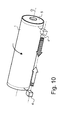
- Figure 9 is a schematic partial side view of a laser engraving system to carry out the method of the invention.
- the printing plate medium 1 is preferably mounted on the circumference of a support cylinder 5 (see also Figure 10 ) which is rotated in front of a movable engraving unit 4 producing a laser beam 2 that is directed towards the surface of the printing plate medium 1, which laser engraving unit 4 is movable parallel to the axis of rotation O of the support cylinder 5.
- the laser engraving unit 4 can be any type of suitable laser engraving unit, for instance a Ytterbium fiber laser unit.
- the laser can conveniently be supplied from a laser source (not illustrated) to a laser head of the unit 4 via an optical fibre cable 40.
- the laser engraving unit 4 is mounted on a frame (not illustrated in Figure 10 ) that is movable parallel to the axis of rotation O of the cylinder 5 between a start position (illustrated on the left-hand side in Figure 10 ) and an end position, designated by reference numeral 4* (on the right-hand side in Figure 10 ).
- the laser engraving unit 4 is movable during each individual engraving step from the start position to the end position (e.g. from left to right in Figure 10 ) step by step along the axis of rotation O of the support cylinder 5 so as to process successive annular portions of the surface of the printing plate medium 1.
- a cleaning unit designated globally by reference numeral 6, is preferably mounted by means of a supporting arm (not shown) on the same frame as the laser engraving unit 4 so as to move together with this latter.
- the supporting arm is designed to enable movement of the cleaning unit 6 between a working position (as illustrated in Figure 9 ) where the cleaning unit 6 is brought into contact with the surface of the printing plate medium 1 carried on the support cylinder 5 and a retracted, inoperative position (not illustrated) where the cleaning unit 6 is moved away from the surface of the printing plate medium 1.
- the cleaning unit 6 is preferably operative while the laser engraving unit 4, which is inoperative, is moved back from the end position to the start position, e.g from right to left in Figure 10 .
- the cleaning unit 6 preferably comprises a rotating brush 9 for brushing the surface of the printing plate medium 1.
- the cleaning unit 6 may advantageously be further provided with an aspiration head 10 for aspirating the residues that are removed from the surface of the printing plate medium 1.
- the rotating brush 9 is located within the aspiration head 10 so that residues can be conveniently aspirated from all areas surrounding the rotating brush 9.
- a rotational speed of the brush 9, pressure between the brush 9 and the surface of the printing plate medium 1 and/or displacement speed of the cleaning unit 6 parallel to the axis of rotation O of the support cylinder 5 is/are advantageously adjustable so as to ensure optimum cleaning efficiency.
- the printing plate medium 1 is advantageously engraved while being held on the support cylinder 5 in the same way as it would be held on the circumference of a plate cylinder of an intaglio printing press.
- This ensures that the engraving profile of the engravings remains substantially unchanged when the engraved printing plate medium 1 is ultimately installed in an intaglio printing press, which is an advantageous over a solution as disclosed in International application No. WO 97/48555 A1 , European patent application No. EP 1 334 822 A2 , International application No. WO 2006/045128 A1 or Deinhammer2006 where the printing plate medium 1 is engraved while being held flat.
- intaglio printing presses are disclosed in European patent applications Nos.
Priority Applications (17)
| Application Number | Priority Date | Filing Date | Title |
|---|---|---|---|
| EP08156392A EP2119527A1 (fr) | 2008-05-16 | 2008-05-16 | Procédé et système pour la fabrication de plaques d'impression en creux pour la production de papiers sécurisés |
| BRPI0908667-6A BRPI0908667B1 (pt) | 2008-05-16 | 2009-05-05 | Método para a fabricação de placas de impressão por entalhe para a produção de papéis de segurança e sistema de gravação a laser |
| EP09746196.6A EP2300192B1 (fr) | 2008-05-16 | 2009-05-05 | Procédé et système de fabrication de plaques d'impression en creux pour la production de papiers infalsifiables |
| US12/992,522 US9796202B2 (en) | 2008-05-16 | 2009-05-05 | Method and system for manufacturing intaglio printing plates for the production of security papers |
| ES09746196.6T ES2471168T3 (es) | 2008-05-16 | 2009-05-05 | Método y sistema para fabricar planchas de calcografía para la producción de papeles de seguridad |
| CN200980116315XA CN102015190A (zh) | 2008-05-16 | 2009-05-05 | 用于制造用于安全纸的生产的凹版印刷板的方法和系统 |
| CA2723738A CA2723738A1 (fr) | 2008-05-16 | 2009-05-05 | Procede et systeme de fabrication de plaques d'impression en creux pour la production de papiers infalsifiables |
| AU2009247637A AU2009247637B2 (en) | 2008-05-16 | 2009-05-05 | Method and system for manufacturing intaglio printing plates for the production of security papers |
| JP2011509049A JP5694919B2 (ja) | 2008-05-16 | 2009-05-05 | 証券を生産するための凹版印刷版の製造の方法とシステム |
| MX2010012505A MX2010012505A (es) | 2008-05-16 | 2009-05-05 | Metodo y sistema para fabricar placas para impresion por grabado en relieve para la produccion de papeles de seguridad. |
| PCT/IB2009/051838 WO2009138901A1 (fr) | 2008-05-16 | 2009-05-05 | Procédé et système de fabrication de plaques d’impression en creux pour la production de papiers infalsifiables |
| KR1020107027539A KR101584691B1 (ko) | 2008-05-16 | 2009-05-05 | 보안 용지의 생성을 위한 음각 인쇄판을 제조하기 위한 방법 및 시스템 |
| RU2010147887/02A RU2505413C2 (ru) | 2008-05-16 | 2009-05-05 | Способ и устройство для изготовления форм для глубокой печати, предназначенных для производства ценных бумаг |
| MYPI2010005113A MY165708A (en) | 2008-05-16 | 2009-05-05 | Method and system for manufacturing intaglio printing plates for the production of security papers |
| CN201410534978.6A CN104475978A (zh) | 2008-05-16 | 2009-05-05 | 用于制造用于安全纸的生产的凹版印刷板的方法和系统 |
| EP14158764.2A EP2743025A3 (fr) | 2008-05-16 | 2009-05-05 | Procédé et système pour la fabrication de plaques d'impression en creux dans la production de papiers sécurisés |
| ZA2010/07807A ZA201007807B (en) | 2008-05-16 | 2010-11-01 | Method and system for manufacturing intaglio printing plates for the production of security papers |
Applications Claiming Priority (1)
| Application Number | Priority Date | Filing Date | Title |
|---|---|---|---|
| EP08156392A EP2119527A1 (fr) | 2008-05-16 | 2008-05-16 | Procédé et système pour la fabrication de plaques d'impression en creux pour la production de papiers sécurisés |
Publications (1)
| Publication Number | Publication Date |
|---|---|
| EP2119527A1 true EP2119527A1 (fr) | 2009-11-18 |
Family
ID=39830055
Family Applications (3)
| Application Number | Title | Priority Date | Filing Date |
|---|---|---|---|
| EP08156392A Withdrawn EP2119527A1 (fr) | 2008-05-16 | 2008-05-16 | Procédé et système pour la fabrication de plaques d'impression en creux pour la production de papiers sécurisés |
| EP09746196.6A Active EP2300192B1 (fr) | 2008-05-16 | 2009-05-05 | Procédé et système de fabrication de plaques d'impression en creux pour la production de papiers infalsifiables |
| EP14158764.2A Withdrawn EP2743025A3 (fr) | 2008-05-16 | 2009-05-05 | Procédé et système pour la fabrication de plaques d'impression en creux dans la production de papiers sécurisés |
Family Applications After (2)
| Application Number | Title | Priority Date | Filing Date |
|---|---|---|---|
| EP09746196.6A Active EP2300192B1 (fr) | 2008-05-16 | 2009-05-05 | Procédé et système de fabrication de plaques d'impression en creux pour la production de papiers infalsifiables |
| EP14158764.2A Withdrawn EP2743025A3 (fr) | 2008-05-16 | 2009-05-05 | Procédé et système pour la fabrication de plaques d'impression en creux dans la production de papiers sécurisés |
Country Status (14)
| Country | Link |
|---|---|
| US (1) | US9796202B2 (fr) |
| EP (3) | EP2119527A1 (fr) |
| JP (1) | JP5694919B2 (fr) |
| KR (1) | KR101584691B1 (fr) |
| CN (2) | CN102015190A (fr) |
| AU (1) | AU2009247637B2 (fr) |
| BR (1) | BRPI0908667B1 (fr) |
| CA (1) | CA2723738A1 (fr) |
| ES (1) | ES2471168T3 (fr) |
| MX (1) | MX2010012505A (fr) |
| MY (1) | MY165708A (fr) |
| RU (1) | RU2505413C2 (fr) |
| WO (1) | WO2009138901A1 (fr) |
| ZA (1) | ZA201007807B (fr) |
Cited By (7)
| Publication number | Priority date | Publication date | Assignee | Title |
|---|---|---|---|---|
| WO2011146290A3 (fr) * | 2010-05-17 | 2012-03-29 | Eastman Kodak Company | Gravure directe de plaques d'impression flexographiques |
| WO2012106128A1 (fr) * | 2011-01-31 | 2012-08-09 | Eastman Kodak Company | Incorporation de données imprimées dans des zones pleines |
| DE102011013423A1 (de) * | 2011-03-07 | 2012-09-13 | abc packmedia GmbH & Co.KG | Verfahren und Einrichtung zur Modellbildung von zu prägenden Objekten und Herstellung eines Prägewerkzeugs |
| AT519582A1 (de) * | 2017-01-30 | 2018-08-15 | Oesterreichische Banknoten Und Sicherheitsdruck Gmbh | Verfahren zum gravieren einer intaglio-stichtiefdruckplatte |
| EP3326830A4 (fr) * | 2015-07-23 | 2019-04-03 | Fujitsu Component Limited | Plaque d'impression, matériau imprimé et procédé d'impression |
| DE102020000104A1 (de) * | 2020-01-10 | 2021-07-15 | Giesecke+Devrient Currency Technology Gmbh | Herstellung eines Prägewerkzeugs und von geprägten Sicherheitselementen |
| EP3851883A4 (fr) * | 2018-09-10 | 2022-03-30 | Toppan Printing Co., Ltd. | Corps d'affichage, feuille de transfert, étiquette adhésive et produits étiquetés |
Families Citing this family (15)
| Publication number | Priority date | Publication date | Assignee | Title |
|---|---|---|---|---|
| EP2119527A1 (fr) | 2008-05-16 | 2009-11-18 | Kba-Giori S.A. | Procédé et système pour la fabrication de plaques d'impression en creux pour la production de papiers sécurisés |
| EP2514594A1 (fr) | 2011-04-18 | 2012-10-24 | KBA-NotaSys SA | Plaque d'impression en creux, son procédé de fabrication et utilisation correspondante |
| EP2650135A1 (fr) | 2012-04-12 | 2013-10-16 | KBA-NotaSys SA | Appareil de revêtement de plaque d'impression en creux |
| EP2746049A1 (fr) | 2012-12-20 | 2014-06-25 | KBA-NotaSys SA | Procédé de contrôle d'une impression taille-douce et gamme de contrôle à cette fin |
| ES2552004T3 (es) | 2013-03-14 | 2015-11-25 | Flooring Technologies Ltd. | Procedimiento para la generación de impresiones decorativas con igual calidad independientemente del procedimiento de impresión usado y un dispositivo para la realización de este procedimiento |
| CH708303B1 (de) * | 2013-07-11 | 2019-02-15 | Terolab Surface Group Sa | Verfahren zur Beschichtung der zylindrischen Oberfläche einer Rasterhülse für eine Druckmaschine und Rasterhülse, die gemäss dieses Verfahrens vorbereitet wird. |
| CN103481638B (zh) * | 2013-09-27 | 2015-05-13 | 东莞运城制版有限公司 | 一种用于镭射纸张印刷的版辊及其制作工艺 |
| JP5910606B2 (ja) * | 2013-10-22 | 2016-04-27 | 株式会社村田製作所 | グラビア印刷版およびその製造方法、グラビア印刷機、ならびに積層セラミック電子部品の製造方法 |
| CN103832102A (zh) * | 2013-12-05 | 2014-06-04 | 浙江万峰包装有限公司 | 一种利用水性油墨进行凹版预印的方法 |
| LU92574B1 (de) * | 2014-10-16 | 2016-04-18 | Windmöller & Hölscher Kg | Verfahren zur erzeugung einer druckbildstruktur |
| EP3047932B1 (fr) * | 2015-01-21 | 2018-12-26 | Agie Charmilles New Technologies SA | Procédé d'ablation par laser en vu de graver une surface avec optimisation de zone de traitement, avec programme et machine correspondants |
| CN106552997B (zh) * | 2015-09-23 | 2018-07-24 | 乐凯华光印刷科技有限公司 | 基于超短脉冲激光烧蚀原理对金属薄板砂目化处理的方法 |
| CN109377861A (zh) * | 2018-12-10 | 2019-02-22 | 无锡百得包装材料有限公司 | 一种防伪标签和印刷防伪标签的印刷版 |
| KR102010918B1 (ko) * | 2019-03-14 | 2019-08-14 | (주)신성마이크로 | 미세 문양이 형성된 스탬핑 포일 제조방법 및 이를 이용하여 제조된 스탬핑 포일 |
| CN110682722B (zh) * | 2019-09-29 | 2022-04-01 | 唐勇军 | 一种具有立体视觉效果的板面及制作方法 |
Citations (29)
| Publication number | Priority date | Publication date | Assignee | Title |
|---|---|---|---|---|
| US3636251A (en) * | 1968-08-28 | 1972-01-18 | Quantronix Corp | Laser facsimile system for engraving printing plates |
| EP0091709A1 (fr) | 1982-04-07 | 1983-10-19 | De La Rue Giori S.A. | Machine taille-douce pour l'impression des papiers valeurs |
| EP0351366A2 (fr) | 1988-07-13 | 1990-01-17 | De La Rue Giori S.A. | Machine d'impression rotative combinée pour papiers de valeur, en particulier billets de banque |
| EP0406157A1 (fr) | 1989-06-29 | 1991-01-02 | De La Rue Giori S.A. | Machine taille-douce pour l'impression des papiers valeurs |
| EP0415881A2 (fr) | 1989-08-30 | 1991-03-06 | De La Rue Giori S.A. | Machine rotative d'impression combinée, particulièrement pour imprimer les papiers de valeur |
| EP0563007A1 (fr) | 1992-03-26 | 1993-09-29 | De La Rue Giori S.A. | Machine à imprimer en creux |
| EP0683123A1 (fr) | 1994-05-20 | 1995-11-22 | De La Rue Giori S.A. | Machine rotative d'impression pourvue d'un dispositif de repérage pour aligner la bande de papier |
| WO1997048555A1 (fr) | 1996-06-17 | 1997-12-24 | Giesecke & Devrient Gmbh | Procede de production de plaques a gaufrer |
| EP0873866A1 (fr) | 1997-04-14 | 1998-10-28 | De La Rue Giori S.A. | Machine taille-douce |
| US20020136969A1 (en) * | 1999-09-03 | 2002-09-26 | Margit Hiller | Recording material comprising silicone rubber and iron oxides for producing relief printing plates by laser engraving |
| EP1334822A2 (fr) | 2002-02-06 | 2003-08-13 | Tech Epikos - S.R.L. | Procédé et installation permettant de graver au laser de plaques ou cylindres chalcographiques |
| EP1369230A1 (fr) * | 2002-06-05 | 2003-12-10 | Kba-Giori S.A. | Procédé de fabrication d'une plaque gravée |
| EP1400353A1 (fr) | 2002-09-19 | 2004-03-24 | Kba-Giori S.A. | Machine d'impression en creux |
| EP1442878A1 (fr) | 2003-02-03 | 2004-08-04 | Kba-Giori S.A. | Entraínement du dispositif d'encrage dans une machine d'impression en creux |
| EP1445098A1 (fr) | 2003-02-04 | 2004-08-11 | Kba-Giori S.A. | Cylindre porte-blanchet pour une machine d'impression en creux |
| EP1448393A1 (fr) | 2001-11-27 | 2004-08-25 | Kba-Giori S.A. | Machine d'impression gravure en creux |
| US20040168595A1 (en) * | 2002-10-17 | 2004-09-02 | Siegfried Beisswenger | Method to produce a printing form for rotogravure, printing form for rotogravure and their use |
| WO2005002869A1 (fr) | 2003-07-03 | 2005-01-13 | Oesterreichische Banknoten- Und Sicherheitsdruck Gmbh | Procede de fabrication d'une plaque d'impression pour l'impression en creux et plaque d'impression pour l'impression en creux |
| EP1529637A1 (fr) * | 2003-10-30 | 2005-05-11 | Houtstra Management & Beheer B.V. | Element pourant être gravé par laser pour la preparation d'une plaque d'impression flexographique, d'un tampon manuel ou d'un tampon pour le codage |
| EP1580020A1 (fr) * | 2004-03-24 | 2005-09-28 | Kba-Giori S.A. | Plaque d'impression en creux |
| EP1580015A1 (fr) | 2004-03-24 | 2005-09-28 | Kba-Giori S.A. | Procédé et appareil permettant d'effectuer un marquage d'identité sur documents de sécurité |
| EP1602482A1 (fr) | 2004-06-03 | 2005-12-07 | Kba-Giori S.A. | Machine intaglio avec des cylindres en phase |
| EP1602483A1 (fr) | 2004-06-03 | 2005-12-07 | Kba-Giori S.A. | Machine d'impression intaglio et procédé correspondant |
| EP1622769A1 (fr) | 2003-05-13 | 2006-02-08 | Kba-Giori S.A. | Rotative en creux pourvue d'un cylindre grave et d'un cylindre d'essuyage rotatif en contact avec le cylindre grave |
| WO2006045128A1 (fr) | 2004-10-28 | 2006-05-04 | Oesterreichische Banknoten- Und Sicherheitsdruck Gmbh | Dispositif pour graver des plaques d'impression |
| EP1704052A1 (fr) | 2004-01-15 | 2006-09-27 | Kba-Giori S.A. | Systeme d'encrage pour machine d'impression en creux |
| US20070107252A1 (en) * | 2003-11-27 | 2007-05-17 | Stork Prints Austria Gmbh | Vacuum extraction unit for a device used to structure the surface of a workpiece by means of radiation |
| WO2007119203A1 (fr) | 2006-04-13 | 2007-10-25 | Kba-Giori S.A. | Procédé de génération de motifs représentant une image en demi-teintes |
| US20070254242A1 (en) * | 2003-11-27 | 2007-11-01 | Xsys Print Solutions Deutschland Gmbh | Method for Producing Flexographic Printing Plates by Means of Laser Engraving |
Family Cites Families (11)
| Publication number | Priority date | Publication date | Assignee | Title |
|---|---|---|---|---|
| DE3008176C2 (de) | 1979-03-07 | 1986-02-20 | Crosfield Electronics Ltd., London | Gravieren von Druckzylindern |
| GB2048785B (en) * | 1979-03-07 | 1982-12-15 | Crosfield Electronics Ltd | Engraving printing cylinders |
| JPH0798274B2 (ja) * | 1986-12-22 | 1995-10-25 | 大成建設株式会社 | レ−ザ−照射による固形材の切断方法及びその装置 |
| DE3807476A1 (de) * | 1988-03-08 | 1989-09-28 | Messerschmitt Boelkow Blohm | Bearbeitungseinrichtung fuer werkstuecke |
| EP0407969B1 (fr) | 1989-07-14 | 1993-10-06 | MAHO Aktiengesellschaft | Procédé et dispositif pour réaliser des espaces creux dans les pièces à usiner au moyen d'un faisceau laser |
| DE69637994D1 (de) * | 1995-04-26 | 2009-09-24 | Minnesota Mining & Mfg | Ablationsverfahren durch laser-darstellung |
| JP4349667B2 (ja) | 1998-07-15 | 2009-10-21 | 株式会社アマダエンジニアリングセンター | バリ取り機 |
| JP3533600B2 (ja) * | 1999-09-08 | 2004-05-31 | リコーマイクロエレクトロニクス株式会社 | 凹版並びに凹版の製造方法及びその装置 |
| ES2233522T3 (es) * | 2001-05-25 | 2005-06-16 | Stork Prints Austria Gmbh | Procedimiento y dispositivo para la fabricacion de un molde. |
| JP3695534B2 (ja) | 2002-08-05 | 2005-09-14 | 独立行政法人 国立印刷局 | 凹版版面及び凹版印刷物 |
| EP2119527A1 (fr) | 2008-05-16 | 2009-11-18 | Kba-Giori S.A. | Procédé et système pour la fabrication de plaques d'impression en creux pour la production de papiers sécurisés |
-
2008
- 2008-05-16 EP EP08156392A patent/EP2119527A1/fr not_active Withdrawn
-
2009
- 2009-05-05 EP EP09746196.6A patent/EP2300192B1/fr active Active
- 2009-05-05 EP EP14158764.2A patent/EP2743025A3/fr not_active Withdrawn
- 2009-05-05 KR KR1020107027539A patent/KR101584691B1/ko active IP Right Grant
- 2009-05-05 RU RU2010147887/02A patent/RU2505413C2/ru active
- 2009-05-05 BR BRPI0908667-6A patent/BRPI0908667B1/pt not_active IP Right Cessation
- 2009-05-05 CN CN200980116315XA patent/CN102015190A/zh active Pending
- 2009-05-05 US US12/992,522 patent/US9796202B2/en active Active
- 2009-05-05 ES ES09746196.6T patent/ES2471168T3/es active Active
- 2009-05-05 CA CA2723738A patent/CA2723738A1/fr not_active Abandoned
- 2009-05-05 CN CN201410534978.6A patent/CN104475978A/zh active Pending
- 2009-05-05 JP JP2011509049A patent/JP5694919B2/ja active Active
- 2009-05-05 MX MX2010012505A patent/MX2010012505A/es active IP Right Grant
- 2009-05-05 AU AU2009247637A patent/AU2009247637B2/en not_active Ceased
- 2009-05-05 WO PCT/IB2009/051838 patent/WO2009138901A1/fr active Application Filing
- 2009-05-05 MY MYPI2010005113A patent/MY165708A/en unknown
-
2010
- 2010-11-01 ZA ZA2010/07807A patent/ZA201007807B/en unknown
Patent Citations (32)
| Publication number | Priority date | Publication date | Assignee | Title |
|---|---|---|---|---|
| US3636251A (en) * | 1968-08-28 | 1972-01-18 | Quantronix Corp | Laser facsimile system for engraving printing plates |
| EP0091709A1 (fr) | 1982-04-07 | 1983-10-19 | De La Rue Giori S.A. | Machine taille-douce pour l'impression des papiers valeurs |
| EP0351366A2 (fr) | 1988-07-13 | 1990-01-17 | De La Rue Giori S.A. | Machine d'impression rotative combinée pour papiers de valeur, en particulier billets de banque |
| EP0406157A1 (fr) | 1989-06-29 | 1991-01-02 | De La Rue Giori S.A. | Machine taille-douce pour l'impression des papiers valeurs |
| EP0415881A2 (fr) | 1989-08-30 | 1991-03-06 | De La Rue Giori S.A. | Machine rotative d'impression combinée, particulièrement pour imprimer les papiers de valeur |
| EP0563007A1 (fr) | 1992-03-26 | 1993-09-29 | De La Rue Giori S.A. | Machine à imprimer en creux |
| EP0683123A1 (fr) | 1994-05-20 | 1995-11-22 | De La Rue Giori S.A. | Machine rotative d'impression pourvue d'un dispositif de repérage pour aligner la bande de papier |
| WO1997048555A1 (fr) | 1996-06-17 | 1997-12-24 | Giesecke & Devrient Gmbh | Procede de production de plaques a gaufrer |
| EP0873866A1 (fr) | 1997-04-14 | 1998-10-28 | De La Rue Giori S.A. | Machine taille-douce |
| US20020136969A1 (en) * | 1999-09-03 | 2002-09-26 | Margit Hiller | Recording material comprising silicone rubber and iron oxides for producing relief printing plates by laser engraving |
| US6511784B1 (en) * | 1999-09-03 | 2003-01-28 | Basf Drucksysteme Gmbh | Recording material comprising silicon rubber and iron oxides for producing relief printing plates by laser engraving |
| EP1448393A1 (fr) | 2001-11-27 | 2004-08-25 | Kba-Giori S.A. | Machine d'impression gravure en creux |
| EP1334822A2 (fr) | 2002-02-06 | 2003-08-13 | Tech Epikos - S.R.L. | Procédé et installation permettant de graver au laser de plaques ou cylindres chalcographiques |
| EP1369230A1 (fr) * | 2002-06-05 | 2003-12-10 | Kba-Giori S.A. | Procédé de fabrication d'une plaque gravée |
| WO2003103962A1 (fr) | 2002-06-05 | 2003-12-18 | Kba-Giori S.A. | Procede de fabrication d'une plaque gravee |
| EP1400353A1 (fr) | 2002-09-19 | 2004-03-24 | Kba-Giori S.A. | Machine d'impression en creux |
| US20040168595A1 (en) * | 2002-10-17 | 2004-09-02 | Siegfried Beisswenger | Method to produce a printing form for rotogravure, printing form for rotogravure and their use |
| EP1442878A1 (fr) | 2003-02-03 | 2004-08-04 | Kba-Giori S.A. | Entraínement du dispositif d'encrage dans une machine d'impression en creux |
| EP1445098A1 (fr) | 2003-02-04 | 2004-08-11 | Kba-Giori S.A. | Cylindre porte-blanchet pour une machine d'impression en creux |
| EP1622769A1 (fr) | 2003-05-13 | 2006-02-08 | Kba-Giori S.A. | Rotative en creux pourvue d'un cylindre grave et d'un cylindre d'essuyage rotatif en contact avec le cylindre grave |
| WO2005002869A1 (fr) | 2003-07-03 | 2005-01-13 | Oesterreichische Banknoten- Und Sicherheitsdruck Gmbh | Procede de fabrication d'une plaque d'impression pour l'impression en creux et plaque d'impression pour l'impression en creux |
| EP1529637A1 (fr) * | 2003-10-30 | 2005-05-11 | Houtstra Management & Beheer B.V. | Element pourant être gravé par laser pour la preparation d'une plaque d'impression flexographique, d'un tampon manuel ou d'un tampon pour le codage |
| US20070254242A1 (en) * | 2003-11-27 | 2007-11-01 | Xsys Print Solutions Deutschland Gmbh | Method for Producing Flexographic Printing Plates by Means of Laser Engraving |
| US20070107252A1 (en) * | 2003-11-27 | 2007-05-17 | Stork Prints Austria Gmbh | Vacuum extraction unit for a device used to structure the surface of a workpiece by means of radiation |
| EP1704052A1 (fr) | 2004-01-15 | 2006-09-27 | Kba-Giori S.A. | Systeme d'encrage pour machine d'impression en creux |
| EP1580015A1 (fr) | 2004-03-24 | 2005-09-28 | Kba-Giori S.A. | Procédé et appareil permettant d'effectuer un marquage d'identité sur documents de sécurité |
| WO2005090090A1 (fr) | 2004-03-24 | 2005-09-29 | Kba-Giori S.A. | Plaque d'impression en creux |
| EP1580020A1 (fr) * | 2004-03-24 | 2005-09-28 | Kba-Giori S.A. | Plaque d'impression en creux |
| EP1602483A1 (fr) | 2004-06-03 | 2005-12-07 | Kba-Giori S.A. | Machine d'impression intaglio et procédé correspondant |
| EP1602482A1 (fr) | 2004-06-03 | 2005-12-07 | Kba-Giori S.A. | Machine intaglio avec des cylindres en phase |
| WO2006045128A1 (fr) | 2004-10-28 | 2006-05-04 | Oesterreichische Banknoten- Und Sicherheitsdruck Gmbh | Dispositif pour graver des plaques d'impression |
| WO2007119203A1 (fr) | 2006-04-13 | 2007-10-25 | Kba-Giori S.A. | Procédé de génération de motifs représentant une image en demi-teintes |
Non-Patent Citations (3)
| Title |
|---|
| HELMUT KIPPHAN: "Handbook of Print Media", 2001, SPRINGER-VERLAG |
| MESSRS. HARALD DEINHAMMER ET AL.: "Direct Laser Engraving of Intaglio Printing Plates", PROCEEDINGS OF SPIE, vol. 5310, 2004, pages 184 - 193, XP002376650, DOI: doi:10.1117/12.526899 |
| MESSRS. HARALD DEINHAMMER ET AL.: "The implication of direct laser engraved intaglio printing plates on banknote security", PROCEEDINGS OF SPIE, vol. 6075, 2006, pages 607503 - 1 |
Cited By (8)
| Publication number | Priority date | Publication date | Assignee | Title |
|---|---|---|---|---|
| WO2011146290A3 (fr) * | 2010-05-17 | 2012-03-29 | Eastman Kodak Company | Gravure directe de plaques d'impression flexographiques |
| WO2012106128A1 (fr) * | 2011-01-31 | 2012-08-09 | Eastman Kodak Company | Incorporation de données imprimées dans des zones pleines |
| DE102011013423A1 (de) * | 2011-03-07 | 2012-09-13 | abc packmedia GmbH & Co.KG | Verfahren und Einrichtung zur Modellbildung von zu prägenden Objekten und Herstellung eines Prägewerkzeugs |
| EP3326830A4 (fr) * | 2015-07-23 | 2019-04-03 | Fujitsu Component Limited | Plaque d'impression, matériau imprimé et procédé d'impression |
| AT519582A1 (de) * | 2017-01-30 | 2018-08-15 | Oesterreichische Banknoten Und Sicherheitsdruck Gmbh | Verfahren zum gravieren einer intaglio-stichtiefdruckplatte |
| AT519582B1 (de) * | 2017-01-30 | 2019-12-15 | Oesterreichische Banknoten Und Sicherheitsdruck Gmbh | Verfahren zum gravieren einer intaglio-stichtiefdruckplatte |
| EP3851883A4 (fr) * | 2018-09-10 | 2022-03-30 | Toppan Printing Co., Ltd. | Corps d'affichage, feuille de transfert, étiquette adhésive et produits étiquetés |
| DE102020000104A1 (de) * | 2020-01-10 | 2021-07-15 | Giesecke+Devrient Currency Technology Gmbh | Herstellung eines Prägewerkzeugs und von geprägten Sicherheitselementen |
Also Published As
| Publication number | Publication date |
|---|---|
| MY165708A (en) | 2018-04-20 |
| KR20110006715A (ko) | 2011-01-20 |
| AU2009247637B2 (en) | 2014-03-20 |
| WO2009138901A1 (fr) | 2009-11-19 |
| ES2471168T3 (es) | 2014-06-25 |
| EP2743025A2 (fr) | 2014-06-18 |
| EP2743025A3 (fr) | 2014-10-01 |
| US9796202B2 (en) | 2017-10-24 |
| JP5694919B2 (ja) | 2015-04-01 |
| BRPI0908667B1 (pt) | 2019-04-24 |
| CA2723738A1 (fr) | 2009-11-19 |
| EP2300192A1 (fr) | 2011-03-30 |
| KR101584691B1 (ko) | 2016-01-12 |
| JP2011521805A (ja) | 2011-07-28 |
| US20110068509A1 (en) | 2011-03-24 |
| EP2300192B1 (fr) | 2014-03-12 |
| RU2010147887A (ru) | 2012-07-10 |
| BRPI0908667A2 (pt) | 2016-06-07 |
| MX2010012505A (es) | 2010-12-07 |
| RU2505413C2 (ru) | 2014-01-27 |
| CN102015190A (zh) | 2011-04-13 |
| AU2009247637A1 (en) | 2009-11-19 |
| ZA201007807B (en) | 2012-02-29 |
| CN104475978A (zh) | 2015-04-01 |
Similar Documents
| Publication | Publication Date | Title |
|---|---|---|
| EP2300192B1 (fr) | Procédé et système de fabrication de plaques d'impression en creux pour la production de papiers infalsifiables | |
| EP1509396B1 (fr) | Procede de fabrication d'une plaque gravee | |
| EP1729969B1 (fr) | Procédé et appareil permettant d'effectuer un marquage d'identité sur documents de sécurité | |
| EP2699420B1 (fr) | Plaque d'impression en creux, son procédé de fabrication et son utilisation | |
| AU2004253597B2 (en) | Method for producing a printing plate for intaglio printing and corresponding printing plate | |
| JP2007535417A6 (ja) | インタグリオ凹版印刷のための版板を製造するための方法及びインタグリオ凹版印刷のための版板 | |
| US20090211472A1 (en) | Gravure printing method with exchangeable printing plate | |
| Hennig et al. | Laser engraving in gravure industry | |
| Hennig et al. | Large Scale Laser Microstructuring in the Printing Industry: Precise and Fast Laser Ablation in Gravur Printform Fabrication | |
| Deinhammer et al. | Direct laser engraving of intaglio printing plates | |
| Hennig et al. | Laser Precision Micro Fabrication in the Printing Industry | |
| Hennig et al. | Large scale laser microstructuring of gravure print rollers |
Legal Events
| Date | Code | Title | Description |
|---|---|---|---|
| PUAI | Public reference made under article 153(3) epc to a published international application that has entered the european phase |
Free format text: ORIGINAL CODE: 0009012 |
|
| AK | Designated contracting states |
Kind code of ref document: A1 Designated state(s): AT BE BG CH CY CZ DE DK EE ES FI FR GB GR HR HU IE IS IT LI LT LU LV MC MT NL NO PL PT RO SE SI SK TR |
|
| AX | Request for extension of the european patent |
Extension state: AL BA MK RS |
|
| RAP1 | Party data changed (applicant data changed or rights of an application transferred) |
Owner name: KBA-GIORI S.A. |
|
| AKX | Designation fees paid | ||
| REG | Reference to a national code |
Ref country code: DE Ref legal event code: 8566 |
|
| STAA | Information on the status of an ep patent application or granted ep patent |
Free format text: STATUS: THE APPLICATION IS DEEMED TO BE WITHDRAWN |
|
| 18D | Application deemed to be withdrawn |
Effective date: 20100519 |