EP2118635B1 - Abschätzen von nicht-äquibiaxialer belastung unter verwendung instrumentierter eindrucktechnik - Google Patents
Abschätzen von nicht-äquibiaxialer belastung unter verwendung instrumentierter eindrucktechnik Download PDFInfo
- Publication number
- EP2118635B1 EP2118635B1 EP07708771.6A EP07708771A EP2118635B1 EP 2118635 B1 EP2118635 B1 EP 2118635B1 EP 07708771 A EP07708771 A EP 07708771A EP 2118635 B1 EP2118635 B1 EP 2118635B1
- Authority
- EP
- European Patent Office
- Prior art keywords
- residual stress
- indentation
- res
- stress
- indenter
- Prior art date
- Legal status (The legal status is an assumption and is not a legal conclusion. Google has not performed a legal analysis and makes no representation as to the accuracy of the status listed.)
- Active
Links
Images


Classifications
-
- G—PHYSICS
- G01—MEASURING; TESTING
- G01N—INVESTIGATING OR ANALYSING MATERIALS BY DETERMINING THEIR CHEMICAL OR PHYSICAL PROPERTIES
- G01N3/00—Investigating strength properties of solid materials by application of mechanical stress
- G01N3/40—Investigating hardness or rebound hardness
- G01N3/42—Investigating hardness or rebound hardness by performing impressions under a steady load by indentors, e.g. sphere, pyramid
-
- G—PHYSICS
- G01—MEASURING; TESTING
- G01N—INVESTIGATING OR ANALYSING MATERIALS BY DETERMINING THEIR CHEMICAL OR PHYSICAL PROPERTIES
- G01N3/00—Investigating strength properties of solid materials by application of mechanical stress
- G01N3/08—Investigating strength properties of solid materials by application of mechanical stress by applying steady tensile or compressive forces
-
- G—PHYSICS
- G01—MEASURING; TESTING
- G01N—INVESTIGATING OR ANALYSING MATERIALS BY DETERMINING THEIR CHEMICAL OR PHYSICAL PROPERTIES
- G01N2203/00—Investigating strength properties of solid materials by application of mechanical stress
- G01N2203/02—Details not specific for a particular testing method
- G01N2203/025—Geometry of the test
- G01N2203/0254—Biaxial, the forces being applied along two normal axes of the specimen
-
- G—PHYSICS
- G01—MEASURING; TESTING
- G01N—INVESTIGATING OR ANALYSING MATERIALS BY DETERMINING THEIR CHEMICAL OR PHYSICAL PROPERTIES
- G01N2203/00—Investigating strength properties of solid materials by application of mechanical stress
- G01N2203/02—Details not specific for a particular testing method
- G01N2203/026—Specifications of the specimen
- G01N2203/0262—Shape of the specimen
- G01N2203/0272—Cruciform specimens
Definitions
- the present invention relates to an instrumented indentation method to non-destructively estimate the mechanical material property. Also, the present invention relates to an estimation of non-equibiaxial residual stress to be applied to an in-field structure and a weldment.
- LI M ET AL "Enhanced microhardness of four modern steels following nitrogen ion implantation", SURFACE AND COATINGS TECHNOLOGY, ELSEVIER, AMSTERDAM, NL, vol. 138, no. 2-3, 16 April 2001 (2001-04-16), pages 220-228, XP027301097, ISSN: 0257-8972 [retrieved on 2001-04-16 ] discloses that samples of two kinds of hot-work steels (Orvar Supreme, QRO 90 Supreme), one cold-work steel (Sverker 21) and one ultra-high-strength aircraft steel (AerMet 100) were implanted with 120 keV N 2 + ions (60 keV/N + ) at doses ranging from 5 ⁇ 10 15 to 1.2 ⁇ 10 17 ions/cm 2 at room temperature.
- the layer thickness used for the calculation of implanted-layer hardness was obtained from a molecular dynamic simulation code (TRIM).
- TIM molecular dynamic simulation code
- the residual stress of the surface after nitrogen ion implantation was measured by X-ray diffraction. Friction and wear properties of the implanted samples were also measured. Nanohardness and Young's modulus were measured for the nitrogen ion implanted layers.
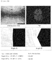
- Grazing angle X-ray diffraction (GXRD) analysis shows the possible formation of nitride phases after nitrogen ion implantation. After nitrogen implantation, samples were depth profiled by AES (Auger Electron Spectrometry) to confirm the depth distribution of the implanted nitrogen ions. Implanted samples showed increased hardness, wear resistance and surface compressive stress.
- US 6,155,104 methods and apparatus for determining from indentation testing the preexisting stress and/or effective strain in a section of a material are provided. It also discloses methods and apparatus for determining the variation of the stress with depth in the material (e.g. the gradient).
- First data are provided from an indentation test of the stressed (or strained) section.
- the stress (or effective strain) can then be determined from the first data and from second data characteristic of the material, such as a stress-strain curve.
- Second data can also be obtain from an additional indentation test of a section having a known stress.
- the methods provided are suitable for programming on a general purpose computer or calculator.
- LEE ET AL "Using the instrumented indentation technique for stress characterization of friction stir-welded API X80 steel", PHILOSOPHICAL MAGAZINE, TAYLOR & FRANCIS LTD. GB, vol. 86, no. 33-35 SPEC. ISSUE, 21 November 2006 (2006-11-21), pages 5497-5504, XP0081435541, ISSN: 1478-6435, DOI: 10.1080/14786430600776330 [retrieved on 2006-11-21 ] relates to using the instrumented indentation technique for stress characterization of friction stir-welded API X80 steel.
- IIT instrumented indentation technique
- the technique is used to characterize the residual stress of a friction stir-welded joint of API X80 steel.
- the indentation load-depth curve is significantly affected by the presence of residual stress and the stress-induced load change at a given penetration is converted to a quantitative stress value through an analytical model. All indentation test results show good agreement with those from an energy-dispersive X-ray diffraction performed to assess the validity of the IIT.
- the microstructures in various regions of the friction stir-welded joint and their effects on local microhardness are discussed.
- One object of the present invention is to non-destnictively estimate non equibiaxial residual stress among the mechanical material properties using a non equibiaxial indenter.
- the present invention provides a method according to claim 1.
- the Knoop indenter may have geometry of 7.11:1 for long and short diagonal lengths.
- the conversion factor ratio may be 0.34.
- the stress directionality (p) may be determined by the formula below with the conversion factor ratio and the indentation load difference ratio.
- the method may further comprise: solving the simultaneous equations in the formula below which contains the conversion factor, and the ratio and the sum of the residual stress, and determining the residual stress of both of the longer and shorter diagonals.
- the method may further comprise: comfirming a relationship between the geometry of the Knoop indenter and the conversion factor ratio through the Finite Element Analysis.
- the present invention provides a computer-readable medium comprising a program for execution on a computing device, wherein the program comprising; steps of the Method for evaluating an asymmetric residual stress for a material by the indentation test.
- the present invention is advantageous in that non-equibiaxial residual stress among the mechanical material properties is non-destructively estimated.
- Residual stress is defined as stress that remains inside the materials after external forces, heat gradient or constraint conditions has been removed. That occurs on heat treatment, welding, casting, cutting, drawing, rolling, extruding, shot peening, coating and the like during all kinds of manufacture or processing. In case of welding, there exists residual stress substantially equal to yield strength. In case of complex materials or thin film, there is accumulated residual stress because of mutual restraint on an interface.
- Residual stress affects the intensity and mechanical property of materials. Residual stress affects progress or deterioration of a fatigue, destruction, corrosion and the like. Therefore, it is very important to perform the accurate analysis for residual stress from structures or facilities to ultrastructures such as electronic products.
- the instrumented indentation method can be applied to all areas from nano to macro scales.
- the mechanical properties such as residual stress, hardness and modulus of elasticity can determined by continuously measuring load and depth values and analyzing the indentation load-depth curves.
- the instrumented indentation method can evaluate residual stress by analyzing both the indentation load difference between stress-free state without residual stress and stress state with residual stress and the difference of contact areas thereon.
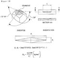
- Knoop indenter is asymmetric indenter with elongated four-sided pyramidal geometry of which has a 7.11:1 for long and short diagonal lengths, referring to FIG.1 . It is proved mathematically and found experimentally that the change on the load-depth curve is dependent on the penetration direction of the Knoop long diagonal by using the Knoop indenter. Only the Knoop indenter is used to determine residual stress for each axis.
- Knoop indenter in FIG.1 as non-equi indenter.
- the Knoop indenter is introduced from F. Knoop, C.G et al.( F. Knoop, C.G. Peters and W.B. Emerson: J. Nat. Bur. Stand., Vol. 23 (1939) p. 39 ).
- Vickers indenter as an equi indenter is limited to measuring only the average residual stress because of symmetrical geometry of Vickers indenter. It is difficult to perform quantitative analysis of the residual stress without knowing the asymmetry coefficient p of residual stress, as expressed in equation 1. However, it is possible to measure only the average residual stress.
- the relationship between the indenation load differences and the average residual stress is expressed in equation 2.
- ⁇ res is the penetration direction of the Knoop long diagonal
- p is the asymmetry coefficient
- L0-L3 is the load difference.
- A is calculated by the Oliver Pharr method.
- the Knoop indenter is the asymmetric indenter with elongated four-sided pyramidal geometry of which has a 7.11:1 for long and short diagonal lengths, as shown in FIG.1 .
- the Knoop indenter yields a indentation load-depth curve changed according to the indenting direction because the asymmetric residual stress functions biaxially, as shown in FIG.2 . Because the tensile residual stress is applied biaxially, the slope of the indentation load-depth curve is lower than that in stress-free state regardless of the indenting direction.
- ⁇ L 1 can be defined as the difference of loads between the intended state where the long diagonal of Knoop indenter is perpendicular to the x-axis and stress-free state at the same indentation depth.
- ⁇ L 2 can be defined as the difference of loads between the intended state where the long diagonal of Knoop indenter is parallel to the x-axis and stress-free state at the same indentation depth.
- the indentation load difference induced from the residual stress at Vickers indentation is proportional to the residual stress of each axis.
- the indentation load-depth curve in the form of the summation, as shown in FIG. 3 .
- the applied residual stress is proportional to the indentation load difference for the Knoop indenter with elongated four-sided pyramidal geometry, similar to the Vickers indenter.
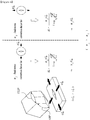
- the relationships between the residual stresses of the long diagonal and the short diagonal, and the indentation load for the asymmetric Knoop indenter are expressed as the equation 6, to introduce the conversion factors, ⁇ ⁇ and ⁇ // , according to the residual stress and the indenting direction, as shown in FIG. 4 and 5 .
- ⁇ L 1 ⁇ ⁇ ⁇ res x + ⁇ / / ⁇ res y
- L 2 ⁇ / / ⁇ res x + ⁇ ⁇ ⁇ res y
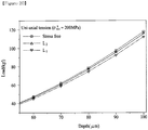
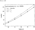
- the experiment shown in FIG.6 is performed to prove the assumption that the effect of the residual stress of each different on the indentation load can be expressed in the form of the summation.
- the sum of the indentaion load difference in that the long diagonal of the indenter is perpendicular and parallel to the direction of the uniaxially applied residual stress of 200MPa is compared with the load difference of the biaxially applied residual stress of 200MPa.
- the indentaion load-depth curve when the long diagonal of the indenter is perpendicular to the direction of the indented residual stress can be defined as Li
- the indentaion load-depth curve when the long diagonal of the indenter is parallel to the direction of the indented residual stress can be defined as L2.
- FIG. 7 shows experimentally that the sum of the indentation load from the uniaxially applied residual stresses is substantially equal to the indentation load difference from the biaxially applied residual stresses inside 5% range except for the initial indenting range. The assumption is proved through this experiment that the effect of the residual stress of each different on the indentation load can be expressed in the form of the summation.
- ⁇ L 1 and ⁇ L 2 can be derived as the sum of the indentation load differences from the residual stress by each axis.
- the ratio of ⁇ Li and ⁇ L2 can be expressed as the residual stress ratio p which defines the directionality of the residual stress.
- ⁇ L 2 ⁇ L 1 ⁇ / / ⁇ res x + ⁇ ⁇ ⁇ res y ⁇ ⁇ ⁇ res x + ⁇ / / ⁇ res y
- the equation 7 can be expressed as equation 8.
- the directionality of the residual stress can be determined by the indentation load difference from two indentations.
- the conversion factor ratio is constant, regardless of the types of materials or the indentation depth. Generally, the conversion factor is a variable affected by the indentation depth. However, it is determined experimentally that the ratio of ⁇ ⁇ and ⁇ // from the direction of the indentation with the Knoop indenter is constant.
- a ⁇ , a // in equation ⁇ are conversion factors dependent on depth variables relating the residual stress to the indentation load difference, and ⁇ x, ⁇ // are determined by the long diagonal direction of the Knoop indenter perpendicular and palellel to the direction of the indented residual stress. Therefore, Q x, a // at the given depth can be determined by the changing the amount of the residual stress. If the experimentally obtained conversion factors are added to equation 9, the sum of the residual stresses is obtained from the indentation load difference .
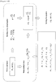
- Equation 8 and 9 are expressed as the sum and the ratio of the residual stresses to get the equation 10.
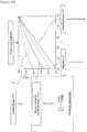
- FIG. 10 shows the procedures to solve the equations for the instrumented indentation test according to one embodiment of the present invention.
- the experiment is performed for evaluating the stress directionality p and the residual stress through the Knoop indentation test described in this specification.
- the residual stress generator generates the biaxially applied residual stress to makes the symmetric/asymmetric stress states at first. And then the instrumented indentation test is performed to obtain the indentation load-depth curve according to the applied stress and the indenting direction. Finally, it is compared with the indentation load-depth curve in stress-free state.
- the actual residue stress ratio and the residual stress of each axis are determined from the indentation load-depth curve change by adopting the above Knoop model.
- the conversion factor ratio is analyzed through the Finite Element Analysis. The introduction to the residual stress generator, the preparation of the specimen, the Knoop indenter, the applied instrumented indentation tester, the experimental procedures and the Finite Element Analysis are described as follows.
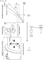
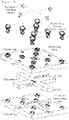
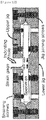
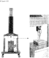
- the newly invented jig apparatus includes the upper and the lower jigs on which grooves is formed respectively to support the cruciform specimen with 40 ⁇ 15 ⁇ 185mm.
- the specimen is loaded inside grooves between the upper and the lower jigs and is fixed by a jig joining screw.
- the bending stress is induced by inserting a specimen bending screw into the screw hole of the upper and the lower jigs.
- Each of tensilely and compressively residual stress is applied to the center area of specimen by inserting a specimen bending screw into the indenting hole of the upper and the lower jigs. It is possible to control the amount of the applied stress by changing the inserting depth of the screw through the strain gauge located at the center area of the specimen.
- a curved supporting part is invented for strongly restricting the center area of the specimen so as to minimize out of plane deformation and at the same time smoothly transmitting the bending stress. Also, when the indentation load is applied to the center area of the bending deformed specimen, the jig joining screws are arranged by four and four on the inner and the outer sides of the upper and the lower jigs, and a rear specimen with 15mm thick for minimizing the reduction of the generated residual stress.
- the specimen in this study is API X65 steel and JIS S45C steel with a chemical components and mechanical properties in table 1. Because the latter steel has a good mechanical property, it is usually used for structural faculty and welding material.
- the above-described rectangular and cruciform specimens are machined and heat-treated in order to remove internal stress.
- Heat-treatment at an appropriate temperature below A 1 for removing the residual stress generated from forge, casting, machining and welding, is regarded as a stress relief annealing. If the steer part with the residuary residual stress is used as it is, the time elapse may reduce the stress so as to let its size and shape change. If a piece of that is cut by machining, the internal stress of the material can't keep its equilibrium, so that it is changed into its new equilibrium to become deformed. For preventing this deformation, it needs to sufficiently remove the residual stress by heating material at an appropriate temperature. Usually it is performed above recrystallization temperature (450°C ) below deformation point Ai. This temperature is maintained for one hour per 25mm thick and then a slowly cooling is performed at 200°C/h.
- recrystallization temperature 450°C
- API X-65 keeps 600°C during about two hours, and then slowly cooling is performed. After the residual stress relief by heat treatment, the yield strength, the modulus of elasticity and the poisson ratio is obtained from the indentation test and the ultrasonic wave speed analysis. The surface is grinded with a sandpaper 100, 200, 400, 600, 800, 1000 or 1500 times for the instrumented indentation test and the attachment of a strain gauge.
- the previous asymmetric Knoop indenter with 7.11:1 as shown in FIG.13 is used for evaluating the asymmetry of the material, which comes from a phenomenon where the length of the long diagonal is changed according to the crystal direction of the material. Evaluating the asymmetry of the material is converted into the hardness so as to obtain the relationship with the crystal direction of the material. There is the previous study to suggest the relationship with the residual stress through the Knoop indenter hardness as shown in FIG 8 .
- the Knoop indenter is manufactured with the geographically identical Knoop indenter shape and consists of diamond, which can apply to the indentation load to the macro scales arrange of above 100kgf.
- the applied instrumented indentation equipment is Frontics Inc.'s AIS3000(maximum load: 300kgf, load resolution: 5.6gf, variable resolution: 0.1 ⁇ m). This equipment synchronizes the load measured by the load cell with the variable signal measured by the variable sensor so as to generate the indentation load-depth curve.
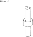
- the indenter holder and the instrumented indentation equipment are manufactured as one body in order to minimize the compliance effect for an equipment, as shown in FIG.14 .
- FIG 15 shows the measured values of the Knoop indenter of FIG. 14 .
- FIG 16 is the photograph of the instrumented indentation equipment applied to one embodiment of the present invention.
- the first is the experimental variable to affect the revival of the indentation load-depth curve as the basic data of the instrumented indentation test.
- This factor may be one or more of the indentation speed, the surface roughness and the indentation depth and so on.
- the spherical indenter indents an API X-65 material at the maximum 150 ⁇ m, and the average size of grains is 10 ⁇ m, there are about tens thousand grains within plastic zone and millions grains within elastic zone.
- the optimized indentation depth is 100 ⁇ m because of the better revival from the repeated experiment at various depth.
- the standard deviations at indentation depth of 20, 40, 60, 80, 100 ⁇ m are compared with each other when the indentation speeds are changed at various roughness.
- the grind condition of the surface and the indentation speed of 0.1mm/min is based on the result of FIG.18 .
- the second is the analysis method as the most important factor.
- the difference between load at stress-free state and load where the residual stress is applied is analyzed per each depth of 10 ⁇ m from 20 ⁇ m to 100 ⁇ m except for the initial depth.
- the experimental procedure to obtain the indentation load-depth curve at stress-free state for each specimen before the residual stress is applied is as follows.
- a cruciform specimen or a rectangular specimen is equipped with the residual stress generator in FIG 11 and then the instrumented indentation test is applied with the indenting hole located at the center of the upper jig.
- Zero index is setup as 1kg.
- the experiment is repeated three times according to each axis of the indenting directions. There is indented with a distance interval of 3mm between the impression shapes in order to prevent overlapping the plastic zone of each other.
- the residual stress is applied within the elastic limit by using Tresca yield condition.
- the curve at the center area is selected as the curve representing each stress state and then analyzed.
- the axis to which the stress-free state and the largest residual stress is added is regarded as the x axis
- the long diagonal of Knoop indenter is perpendicular to the x-axis and the y-axis to obtain the indentation load-depth curve and then ⁇ L 1 and ⁇ L 2 are determined as the load differences obtained from each of depths through that.
- the experiment shown in FIG.6 is performed to prove the assumption that the effect of the residual stress of each different on the indentation load can be expressed in the form of the summation.
- the sum of the indentaion load difference in that the long diagonal of the indenter is perpendicular and parallel to the direction of the uniaxially applied residual stress of 200MPa is compared with the load difference of the biaxially applied residual stress of 200MPa.
- the conversion factor ⁇ ⁇ , ⁇ // in equation 6 are the constant determined by the indentation depth and associated between the residual stress and the induced load from the residual stress when the residual stress is uniaxially applied and the direction of the residual stress is perpendicular or parallel to the direction of the indentation with the Knoop indenter. There can determine ⁇ ⁇ or ⁇ // at each depth along with changing the amount of the residual stress.
- FIG. 19 is a mimetic diagram of the applied experiment for determining the conversion factor. There can determine the residual stress and the anisotropic factor of that from the ratio and the sum of conversion factors at each depth.
- the anisotropic factor of the residual stress is determined by using the load difference and the load ratio. The result is compared with the actual residual stress ratio.
- the sum of the residual stress is determined from the sum of the load difference and gives the residual stress of each axis from solving simultaneous equations with the residual stress ratio. The residual stress is compared with the actual residual stress applied at each axis.
- the input file is generated by MSC. Patran in order to perform the computer simulation of the Knoop indentation test and the finite element analysis is performed by ABAQUS finite element code.
- the geographic shape of the Knoop indenter has 2-fold symmetry to perform the modeling by 1/4 of all specimens.
- the 3-D specimen is constructed by 32,160 of 8-node brick element.
- the reduced integration is introduced in order to reduce the computing time.
- the von Mises yield condition is applied for the finite element analysis.
- the bottom surface of the specimen is fixed to the axial direction and the symmetry boundary condition is applied across the centric surface.
- the indenter has a rigid body and the specimen may be plastic.
- the API X-65 is applied to the finite element analysis of the instrumented indentation test.
- the plastic movement uses the measured modulus of elasticity in 3.2.1 section, the yield strength and the poisson ratio, while the plastic movement is modeled by using the tension curve of the material which is obtained from the uniaxial tension test.
- the maximum indentation depth is 120 ⁇ m and the computer mimitation of the Knoop indentation test is performed by controlling the indentation depth.
- the indentation load-depth curves when the long diagonal of the Knoop indenter is perpendicular to either x or y axes are referred as L 1 and L 2 , respectively.
- FIGs 20 to 22 show the results when they are overlapped with the curve in stress-free state. These results also show that all indentation loads of the applied specimen in this specification are 100kgf when the indented depth is 100 ⁇ m. These results show that when the residual stresses of stress-free and equi-biaxial states are applied, the indentation load-depth curves are constant without the indenting direction. It may be known that what the change of hardness happens according to the indenting direction of the Knoop indenter in either the microhardness test or the nano-indentation test means that the effect on the crystallized direction of the material is great.
- the conversion factor ⁇ ⁇ and ⁇ // in equation 6 are the constant determined by the indentation depth and associated between the residual stress and the induced load induced from the residual stress when the residual stress is uniaxially applied and the direction of the residual stress is perpendicular or parallel to the direction of the indentation with the Knoop indenter. There can determine ⁇ ⁇ or ⁇ // at each depth along with changing the amount of the residual stress.
- FIG. 23 includes the graphs to linearly connect the load differences with the starting point of coordinate when the uniaxial residual stresses of 208, 389 MPa are applied. Only one line with the above three points is determined. What this fitted line is similar to the straight line is the same as the previous study by Vicker indenter, which means that the load difference is generated relative to the residual stress.
- FIG. 24 draws the conversion factors ⁇ x, ⁇ // according to the indentation depth. As shown in FIG.24 , the conversion factors ⁇ ⁇ r ⁇ // tend to be increased as the indentation depth become larger. What the conversion factors at each depth are directly determined and then the conversion factor ratio is determined as their ratio, is referred as a forward method.
- This method is referred as a reverse method. As both values from forward and reverse methods are compared with each other, so the proposed direct summation is confirmed and the validity of this modeling is proved. If the conversion factors are determined regarding the indenting direction and their ratio is equal to the value from equation 12 by modeling, the direct summation must be proved.
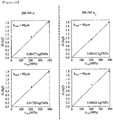
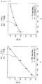
- FIGs. 25 and 26 show the conversion factor ratios for API X-65.
- FIGs 27 and 28 show the conversion factor ratios for ASTM A35.
- FIGs. 29 and 30 show the conversion factor ratios for JIS S45C.
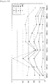
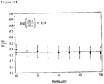
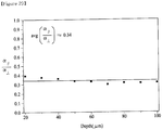
- FIG 31 comparatively show the conversion factor ratios for the above three steels at each depth at the same time. It is found in FIG.32 that the conversion factor ratios tend to be about 0.34 regardless of the indentation depth.
- the conversion factor ratios by the forward method of API X-65 and ASTM A36 are about 0.35 and 0.31, respectively. As they are regarded as an experimental error, the relationship between the amount of the residual stress and the load difference is analyzed by the data from each material.
- the indentation load difference is generated relative to the amount of the residual stress regardless of the material. It is determined from this result that the conversion factor ratio is 0.34. Although only three kinds of steels are related with the above result, six kinds of the residual stresses are applied and it is found that this result is proportional to the amount of them. As their ratio is constant regardless of indentation depth, it is determined that the conversion factor ratio is a variable to relate the Knoop indenter to the biaxial residual stress.
- the conversion factor ratio is a function of the asymmetry of the indenter. It is confirmed in this specification that the indentation load difference is generated relative to the residual stress of each axis and the indentation load difference of each axis in the biaxial state can be expressed in the form of the summation.
- the residual stress of each axis is compared with the actual residual stress.
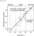
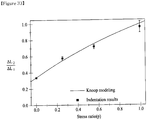
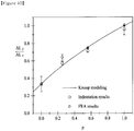
- FIG.33 show that the indentation load difference from the instrumented indentation test for API X-65 is compared with the actual residual stress p when variou kinds of residual stresses are applied.
- the function fitted by equation 14 is equal to this indentation result, which means that the Knoop modeling is valid.
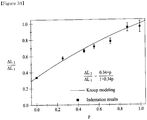
- FIG.34 shows the ratio of the indentation load difference from the instrumented indentation test to the actual residual stress after the residual stress with the biaxial tension is applied to the three kinds of steels in this specification. It is found that the asymmetry coefficient p of the residual stress is determined from the indentation load difference.
- FIG.35 is the graph to show the sum of the conversion factors, ⁇ ⁇ , ⁇ // according to indentation depth.
- the sum of the conversion factor per each depth can be calculated to the sum of the residual stresses through equation 15.
- ⁇ res x + ⁇ res y ⁇ L 1 + ⁇ L 2 ⁇ ⁇ + ⁇ / /
- the ratio and the sum of the residual stresses may be changed into the residual stress of each axis.
- it shows the result of the residual stress when the residual stress with uni-axial tension of 208MPa is applied.
- FIG. 36 shows the result of the Knoop indentation test for the API X-65 cruciform specimen to which the residual stress with uni-axial tension of 208MPa is applied. The sum of the indentation load differences is induced from the indentation load differences ⁇ L 1 and ⁇ L 2 . If the simultaneous equations in equation 14 and 15 are solved, the ratio and the sum of the residual stresses may be changed into the residual stress of each axis, which is shown in the table 2.
- FIG 37 shows the calculated residual stresses from the above procedure.
- [Table 2] ⁇ L 1 + ⁇ L 2 ⁇ res x + ⁇ res y ⁇ res x ⁇ res y 20 0.388877 167.6766 170.1177 -2.44119 30 0.820807 198.2626 201.1491 -2.88649 40 1.404737 213.8108 216.9237 -3.11285 50 2.140667 218.8821 222.0688 -3.18669 60 3.028597 221.5506 224.7762 -3.22554 70 4.068527 232.4873 235.872 -3.38476 80 5.260458 237.4924 240.9501 -3.45763 90 6.604388 242.7191 246.2529 -3.53373 100 8.100318 247.7919 251.3995 -3.60758 AVG. 3.535264 220.0748 223.2789 -3.20405
- the change of the indentation depth may affect the amount of the finally decided residual stress.
- the ratio of the residual stresses is determined from the conversion factor ratio which is constant regardless of the indentation depth, it has constant value regardless of the indentation depth. Consequently, the determination of the residual stress leads to the research against the physical meaning of following conversion factor.
- the previous calculated conversion factor ratio is the function of the asymmetry for the knoop indenter.
- the symmetric indenter such as the vickers indenter produces only one indentation load-depth curve in various residual stresses regardless of the indenting direction and the indentation load difference is proportional to the average amount of residual stress.
- the asymmetric Knoop indenter with asymmetry axis length ratio of 7.11:1 produces the different indentation load-depth curve in various residual stresses regarding the indenting direction.
- the longer diagonal of the knoop indenter is perpendicular or parallel to the applied direction of the residual stress with the largest tension, the indentation load tends to be relatively either the smallest or the largest. As the asymmetry is larger, so it may be reflected of its effect on a large scale, as shown in FIG. 38 .
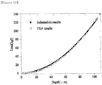
- FIG. 39 shows that the experimental result when the Knoop indenter is indented on API X-65 of stress-free state is compared with that obtained by using the FEA. It is proved that the FEA is valid because the experimental result is equal to that from the FEA.
- FIG.40 show the result from the computer simulation after the biaxial residual stress equal to the actual experimental value is applied. It is shown that the result is matched with the fitted line with the Knoop modeling in 5.2.1 section.
- the conversion factor ratio is 0.63 higher than 0.34 in the actual Knoop indenter.
- the conversion factor ratio is 0.14.
- the conversion factor ratio is the constant which is decided by the asymmetry of the indenter and the higher asymmetry leads to the effect of only one axis on the residual stress.
- the conversion factor ratio may be the function of the asymmetry of the indenter.
- the FEA is performed with Knoop indenter with 3.5:1 and 14:1 and only the tendency is observed. It is expected that the studies about the geometry of the indenter and the conversion factor ratio will appear soon.
- the directionality of biaxial residual stress and the residual stress for each axis were determined by using non-equi indenter such as the Knoop indenter.
- the previous study needed to determine the directionality (p) of residual stress in order to evaluate the residual stress by using the symmetric indenter.
Landscapes
- Physics & Mathematics (AREA)
- Health & Medical Sciences (AREA)
- Life Sciences & Earth Sciences (AREA)
- Chemical & Material Sciences (AREA)
- Analytical Chemistry (AREA)
- Biochemistry (AREA)
- General Health & Medical Sciences (AREA)
- General Physics & Mathematics (AREA)
- Immunology (AREA)
- Pathology (AREA)
- Investigating Strength Of Materials By Application Of Mechanical Stress (AREA)
Claims (7)
- Verfahren zum Beurteilen einer asymmetrischen Restbeanspruchung für ein Material durch eine Eindringprüfung, das Folgendes umfasst: Aufbringen der Restbeanspruchungen σx res und σy res mit uniaxialen und symmetrischen biaxialen Spannungen auf das Material und dann Durchführen einer instrumentierten Eindringprüfung durch Eindrücken eines Knoop-Eindringkörpers in das Material; Vergleichen einer Steigung einer Eindringlasttiefenkurve, wenn die lange Diagonalrichtung des Knoop-Eindringkörpers senkrecht zur Richtung der größten Restbeanspruchung steht, mit der im unbeanspruchten Zustand und dann einer Steigung der Eindringlasttiefenkurve, wenn die lange Diagonalrichtung des Knoop-Eindringkörpers parallel zur Richtung der längsten Restbeanspruchung steht, mit der im unbeanspruchten Zustand, um die asymmetrische Restbeanspruchung für das Material zu beurteilen; Bestimmen des Verhältnisses des Umrechnungsfaktors (α ⊥, α //), das die Restbeanspruchung gemäß der uniaxialen Restbeanspruchung und der längeren Diagonalrichtung des asymmetrischen Eindringkörpers mit der bewirkten Eindringlastdifferenz verknüpft, und das definiert ist durch


- Verfahren nach Anspruch 1, wobei der Knoop-Eindringkörper eine Geometrie von 7,11:1 für lange und kurze diagonale Längen aufweist.
- Verfahren nach Anspruch 2, wobei das Umrechnungsfaktorverhältnis 0,34 ist.
- Verfahren nach Anspruch 3, wobei die Beanspruchungsdirektionalität (p) mit der nachstehenden Formel mit dem Umrechnungsfaktorverhältnis und dem Eindringlastdifferenzverhältnis bestimmt wird

- Verfahren nach Anspruch 4, das ferner Folgendes umfasst: Lösen der gleichzeitigen Gleichungen in der nachstehenden Formel, die den Umrechnungsfaktor sowie das Verhältnis und die Summe der Restbeanspruchung enthält, und Bestimmen der Restbeanspruchung sowohl der längeren als auch der kürzeren Diagonale


- Verfahren nach Anspruch 5, das ferner Folgendes umfasst: Bestätigen der Beziehung zwischen der Geometrie des Knoop-Eindringkörpers und dem Umrechnungsfaktorverhältnis mittels der Finite-Elemente-Analyse.
- Computerlesbares Medium, das ein Programm zur Ausführung auf einer Datenverarbeitungsvorrichtung umfasst, wobei das Programm die Schritte des Verfahrens zum Beurteilen einer asymmetrischen Restbeanspruchung für ein Material durch eine Eindringprüfung gemäß einem der Ansprüche 1 bis 6 umfasst.
Applications Claiming Priority (1)
| Application Number | Priority Date | Filing Date | Title |
|---|---|---|---|
| PCT/KR2007/000621 WO2008096914A1 (en) | 2007-02-06 | 2007-02-06 | Estimation of non-equibiaxial stress using instrumented indentation technique |
Publications (3)
| Publication Number | Publication Date |
|---|---|
| EP2118635A1 EP2118635A1 (de) | 2009-11-18 |
| EP2118635A4 EP2118635A4 (de) | 2011-11-09 |
| EP2118635B1 true EP2118635B1 (de) | 2019-10-09 |
Family
ID=39681805
Family Applications (1)
| Application Number | Title | Priority Date | Filing Date |
|---|---|---|---|
| EP07708771.6A Active EP2118635B1 (de) | 2007-02-06 | 2007-02-06 | Abschätzen von nicht-äquibiaxialer belastung unter verwendung instrumentierter eindrucktechnik |
Country Status (5)
| Country | Link |
|---|---|
| US (1) | US8214162B2 (de) |
| EP (1) | EP2118635B1 (de) |
| JP (1) | JP5017600B2 (de) |
| KR (1) | KR101152323B1 (de) |
| WO (1) | WO2008096914A1 (de) |
Families Citing this family (27)
| Publication number | Priority date | Publication date | Assignee | Title |
|---|---|---|---|---|
| JP5148459B2 (ja) * | 2008-11-20 | 2013-02-20 | 日立Geニュークリア・エナジー株式会社 | 残留応力測定装置及び方法 |
| CN102507318B (zh) * | 2011-10-20 | 2013-11-13 | 中国人民解放军装甲兵工程学院 | 一种等双轴残余应力施加装置 |
| KR101471938B1 (ko) * | 2013-01-31 | 2014-12-11 | (주)프론틱스 | 계장화 압입 시험을 이용한 잔류응력 평가 방법 및 주응력 평가 방법 |
| KR101373059B1 (ko) * | 2013-01-31 | 2014-03-11 | (주)프론틱스 | 계장화 압입 시험을 이용한 잔류응력 평가 방법 |
| CN103439206B (zh) * | 2013-09-13 | 2015-03-25 | 徐州工程学院 | 基于微压痕法的韧性块体材料微小区域残余应力测试方法 |
| AU2015219079A1 (en) | 2014-02-19 | 2016-09-01 | Osmose Utilities Services, Inc. | Automated profiling of the hardness of wood |
| KR101655566B1 (ko) | 2014-11-10 | 2016-09-07 | 현대자동차주식회사 | 유리소재 안전성 평가 장치 및 평가 방법 |
| US9921128B2 (en) | 2015-03-27 | 2018-03-20 | Exponential Business And Technologies Company | Method and apparatus for residual stress measurement through indentation with in-situ generated reference |
| RU2611698C1 (ru) * | 2015-12-07 | 2017-02-28 | Федеральное государственное бюджетное учреждение науки Институт механики Уральского отделения Российской академии наук | Способ определения модуля упругости юнга материала микро- и наночастиц |
| US11041791B2 (en) * | 2017-08-10 | 2021-06-22 | Sumitomo Electric Industries, Ltd. | Indenter made of polycrystalline diamond, and method and apparatus using the same for evaluating crack initiation load |
| CN108132193B (zh) * | 2017-12-21 | 2020-06-16 | 西北工业大学 | 一种基于球形压痕形貌识别材料各向异性塑性参数的方法 |
| WO2020017039A1 (ja) * | 2018-07-20 | 2020-01-23 | 住友電気工業株式会社 | ダイヤモンド多結晶体及びそれを備えた工具 |
| CN109239316B (zh) * | 2018-08-08 | 2021-05-18 | 哈尔滨工业大学(深圳) | 一种基于混凝土强度监测装置的混凝土强度监测方法 |
| CN109187180B (zh) * | 2018-08-16 | 2021-08-24 | 东南大学 | 一种基于双轴拉伸试验的材料泊松比测量方法 |
| CN110118696B (zh) * | 2019-05-20 | 2021-07-23 | 吉林大学 | 纳米压痕结合疲劳载荷诱导Zr基非晶合金纳米晶化的方法 |
| CN110261020A (zh) * | 2019-06-18 | 2019-09-20 | 浙江工业大学 | 适用于测量非等轴残余应力的四压头组件 |
| CN110261021B (zh) * | 2019-06-18 | 2024-04-12 | 浙江工业大学 | 一种适用于测量非等轴残余应力的旋转压头组件 |
| EP3987271A1 (de) * | 2019-06-24 | 2022-04-27 | Nanyang Technological University | Maschinenlernverfahren zur schätzung der mechanischen eigenschaften von materialien |
| CN110568001B (zh) * | 2019-08-14 | 2021-09-03 | 武汉科技大学 | 一种确定冷弯厚壁型钢弯角去应力退火温度的方法 |
| CN110595658A (zh) * | 2019-09-27 | 2019-12-20 | 浙江工业大学 | 一种保持中心位置不动的残余应力引入装置 |
| CN113049425B (zh) * | 2021-03-19 | 2022-03-08 | 西安电子科技大学 | 一种采用球形压痕形貌识别金属材料塑性力学参数的方法 |
| CN113188890B (zh) * | 2021-04-29 | 2022-03-08 | 北京科技大学 | 一种利用纳米压痕技术测量材料表面残余应力的方法 |
| CN114518298B (zh) * | 2022-01-14 | 2023-09-29 | 东南大学 | 一种非等双轴残余应力的压入标定方法 |
| CN114777979B (zh) * | 2022-04-25 | 2023-10-13 | 中国石油大学(华东) | 基于压入能量差法的非均匀焊接接头残余应力测试方法 |
| KR102873649B1 (ko) * | 2022-10-14 | 2025-10-21 | (주)프론틱스 | 연속압입시험을 활용한 깊이에 따른 잔류응력 분포 평가 시스템 |
| JP7700809B2 (ja) * | 2023-02-15 | 2025-07-01 | Jfeスチール株式会社 | 金属板構造物の製造方法 |
| CN120633292B (zh) * | 2025-05-28 | 2026-01-06 | 太原理工大学 | 一种基于纳米压痕技术计算残余应力的方法 |
Family Cites Families (16)
| Publication number | Priority date | Publication date | Assignee | Title |
|---|---|---|---|---|
| US5003982A (en) * | 1989-07-28 | 1991-04-02 | Johns Hopkins University | Dynamic indentation system |
| JP2731864B2 (ja) * | 1989-09-05 | 1998-03-25 | 新日本製鐵株式会社 | 押込型硬度計 |
| JPH07508665A (ja) * | 1992-04-21 | 1995-09-28 | ボード・オヴ・リージェンツ,ザ・ユニヴァーシティ・オヴ・テキサス・システム | 関節鏡検査用の押込装置及びその使用方法 |
| US5432595A (en) * | 1993-07-13 | 1995-07-11 | Pechersky; Martin J. | Method for measuring residual stresses in materials by plastically deforming the material and interference pattern comparison |
| US6134954A (en) * | 1996-04-15 | 2000-10-24 | Massachusetts Institute Of Technology | Depth sensing indentation and methodology for mechanical property measurements |
| US6155104A (en) * | 1998-05-26 | 2000-12-05 | Subra Suresh | Method and apparatus for determining preexisting stresses based on indentation or other mechanical probing of a material |
| JP2001349815A (ja) * | 2000-06-07 | 2001-12-21 | Bridgestone Corp | 薄膜の硬度、弾性率の測定方法及び測定装置 |
| US6568250B1 (en) * | 2000-09-22 | 2003-05-27 | International Business Machines Corporation | Apparatus and method for determining residual stress |
| JP3702203B2 (ja) * | 2001-01-12 | 2005-10-05 | ドンイル,クォン | 連続圧入試験のための圧入試験機、これを用いた物性測定方法及び物性計算方法 |
| US6470756B1 (en) * | 2001-02-23 | 2002-10-29 | The Regents Of The University Of California | System and method for measuring residual stress |
| KR100416723B1 (ko) | 2002-04-04 | 2004-01-31 | (주)프론틱스 | 잔류응력 측정장치 및 이 장치를 이용한 잔류응력 데이터측정방법, 잔류응력 측정방법 및 이 측정방법을 기록한기록매체 |
| US7165463B2 (en) * | 2003-10-14 | 2007-01-23 | Northwestern University | Determination of young's modulus and poisson's ratio of coatings from indentation data |
| KR100491295B1 (ko) * | 2004-11-09 | 2005-05-24 | (주)프론틱스 | 연속압입법을 이용한 파괴인성 측정방법 |
| KR100517857B1 (ko) * | 2004-12-16 | 2005-09-30 | (주)프론틱스 | 연속압입시험법을 이용한 잔류응력 측정방법 |
| TWI282858B (en) * | 2005-12-30 | 2007-06-21 | Ind Tech Res Inst | Nano-indentation ultrasonic detecting system and method thereof |
| JP4328349B2 (ja) * | 2006-11-29 | 2009-09-09 | 株式会社日立製作所 | 残留応力測定方法及び装置 |
-
2007
- 2007-02-06 US US12/526,166 patent/US8214162B2/en active Active
- 2007-02-06 JP JP2009548978A patent/JP5017600B2/ja active Active
- 2007-02-06 KR KR1020097016242A patent/KR101152323B1/ko active Active
- 2007-02-06 WO PCT/KR2007/000621 patent/WO2008096914A1/en not_active Ceased
- 2007-02-06 EP EP07708771.6A patent/EP2118635B1/de active Active
Non-Patent Citations (1)
| Title |
|---|
| None * |
Also Published As
| Publication number | Publication date |
|---|---|
| US8214162B2 (en) | 2012-07-03 |
| US20100198530A1 (en) | 2010-08-05 |
| EP2118635A1 (de) | 2009-11-18 |
| JP2010518392A (ja) | 2010-05-27 |
| EP2118635A4 (de) | 2011-11-09 |
| WO2008096914A1 (en) | 2008-08-14 |
| KR101152323B1 (ko) | 2012-06-11 |
| KR20100004940A (ko) | 2010-01-13 |
| JP5017600B2 (ja) | 2012-09-05 |
Similar Documents
| Publication | Publication Date | Title |
|---|---|---|
| EP2118635B1 (de) | Abschätzen von nicht-äquibiaxialer belastung unter verwendung instrumentierter eindrucktechnik | |
| Lee et al. | Estimation of biaxial surface stress by instrumented indentation with sharp indenters | |
| Carlsson et al. | On the determination of residual stress and strain fields by sharp indentation testing.: Part II: experimental investigation | |
| Warren et al. | The influence of machining induced residual stress and phase transformation on the measurement of subsurface mechanical behavior using nanoindentation | |
| Wong et al. | Fracturing and failure behavior of Carrara marble in quasistatic and dynamic Brazilian disc tests | |
| Giri et al. | On the estimation of error in measuring the residual stress by strain gauge rosette | |
| Moharrami et al. | Developing a method in measuring residual stress on steel alloys by instrumented indentation technique | |
| Li et al. | Effects of machine stiffness on the loading–displacement curve during spherical nano-indentation | |
| Xiaokun et al. | Residual stress indentation model based on material equivalence | |
| Kese et al. | Experimental evaluation of nanoindentation as a technique for measuring the hardness and Young’s modulus of Zircaloy-2 sheet material | |
| Pham et al. | Characteristics of microstructural phases relevant to the mechanical properties in structural steel weld zone studied by using indentation | |
| Bellemare et al. | A new method for evaluating the plastic properties of materials through instrumented frictional sliding tests | |
| Rao et al. | On characterisation of local stress–strain properties in friction stir welded aluminium AA 5083 sheets using micro-tensile specimen testing and instrumented indentation technique | |
| Lee et al. | Stress measurement of SS400 steel beam using the continuous indentation technique | |
| Jacq et al. | On the influence of residual stresses in determining the micro-yield stress profile in a nitrided steel by nano-indentation | |
| Lee et al. | Using the instrumented indentation technique for stress characterization of friction stir-welded API X80 steel | |
| Chollacoop et al. | Experimental assessment of the representative strains in instrumented sharp indentation | |
| Choi et al. | Evaluation of nonequibiaxial residual stress using Knoop indenter | |
| Ghanbari et al. | Residual stress asymmetry in thin sheets of double-sided shot peened aluminum | |
| Baxevani et al. | The modified Rockwell test: a new probe for mechanical properties of metals | |
| Allen et al. | Reducing indentation size effect in metals by load function selection | |
| Frolova et al. | Identification of zones of local hydrogen embrittlement of metals by the acoustoelastic effect | |
| Cebron et al. | Effect of cutting on surface hardness and residual stresses for 12Mn austenitic steel | |
| Choi et al. | Application of instrumented indentation technique to estimate strength and residual stress | |
| Laubscher et al. | Residual stress depth profiling by layer removal |
Legal Events
| Date | Code | Title | Description |
|---|---|---|---|
| PUAI | Public reference made under article 153(3) epc to a published international application that has entered the european phase |
Free format text: ORIGINAL CODE: 0009012 |
|
| 17P | Request for examination filed |
Effective date: 20090803 |
|
| AK | Designated contracting states |
Kind code of ref document: A1 Designated state(s): AT BE BG CH CY CZ DE DK EE ES FI FR GB GR HU IE IS IT LI LT LU LV MC NL PL PT RO SE SI SK TR |
|
| DAX | Request for extension of the european patent (deleted) | ||
| A4 | Supplementary search report drawn up and despatched |
Effective date: 20111012 |
|
| RIC1 | Information provided on ipc code assigned before grant |
Ipc: G01N 3/42 20060101ALI20111006BHEP Ipc: G01N 3/08 20060101AFI20111006BHEP Ipc: G01N 3/00 20060101ALI20111006BHEP |
|
| STAA | Information on the status of an ep patent application or granted ep patent |
Free format text: STATUS: EXAMINATION IS IN PROGRESS |
|
| 17Q | First examination report despatched |
Effective date: 20161207 |
|
| GRAP | Despatch of communication of intention to grant a patent |
Free format text: ORIGINAL CODE: EPIDOSNIGR1 |
|
| STAA | Information on the status of an ep patent application or granted ep patent |
Free format text: STATUS: GRANT OF PATENT IS INTENDED |
|
| INTG | Intention to grant announced |
Effective date: 20190430 |
|
| GRAS | Grant fee paid |
Free format text: ORIGINAL CODE: EPIDOSNIGR3 |
|
| GRAA | (expected) grant |
Free format text: ORIGINAL CODE: 0009210 |
|
| STAA | Information on the status of an ep patent application or granted ep patent |
Free format text: STATUS: THE PATENT HAS BEEN GRANTED |
|
| AK | Designated contracting states |
Kind code of ref document: B1 Designated state(s): AT BE BG CH CY CZ DE DK EE ES FI FR GB GR HU IE IS IT LI LT LU LV MC NL PL PT RO SE SI SK TR |
|
| REG | Reference to a national code |
Ref country code: GB Ref legal event code: FG4D |
|
| REG | Reference to a national code |
Ref country code: CH Ref legal event code: EP |
|
| REG | Reference to a national code |
Ref country code: IE Ref legal event code: FG4D |
|
| REG | Reference to a national code |
Ref country code: DE Ref legal event code: R096 Ref document number: 602007059325 Country of ref document: DE |
|
| REG | Reference to a national code |
Ref country code: AT Ref legal event code: REF Ref document number: 1189401 Country of ref document: AT Kind code of ref document: T Effective date: 20191115 |
|
| REG | Reference to a national code |
Ref country code: NL Ref legal event code: MP Effective date: 20191009 |
|
| REG | Reference to a national code |
Ref country code: LT Ref legal event code: MG4D |
|
| REG | Reference to a national code |
Ref country code: AT Ref legal event code: MK05 Ref document number: 1189401 Country of ref document: AT Kind code of ref document: T Effective date: 20191009 |
|
| PG25 | Lapsed in a contracting state [announced via postgrant information from national office to epo] |
Ref country code: BG Free format text: LAPSE BECAUSE OF FAILURE TO SUBMIT A TRANSLATION OF THE DESCRIPTION OR TO PAY THE FEE WITHIN THE PRESCRIBED TIME-LIMIT Effective date: 20200109 Ref country code: FI Free format text: LAPSE BECAUSE OF FAILURE TO SUBMIT A TRANSLATION OF THE DESCRIPTION OR TO PAY THE FEE WITHIN THE PRESCRIBED TIME-LIMIT Effective date: 20191009 Ref country code: GR Free format text: LAPSE BECAUSE OF FAILURE TO SUBMIT A TRANSLATION OF THE DESCRIPTION OR TO PAY THE FEE WITHIN THE PRESCRIBED TIME-LIMIT Effective date: 20200110 Ref country code: NL Free format text: LAPSE BECAUSE OF FAILURE TO SUBMIT A TRANSLATION OF THE DESCRIPTION OR TO PAY THE FEE WITHIN THE PRESCRIBED TIME-LIMIT Effective date: 20191009 Ref country code: AT Free format text: LAPSE BECAUSE OF FAILURE TO SUBMIT A TRANSLATION OF THE DESCRIPTION OR TO PAY THE FEE WITHIN THE PRESCRIBED TIME-LIMIT Effective date: 20191009 Ref country code: SE Free format text: LAPSE BECAUSE OF FAILURE TO SUBMIT A TRANSLATION OF THE DESCRIPTION OR TO PAY THE FEE WITHIN THE PRESCRIBED TIME-LIMIT Effective date: 20191009 Ref country code: LV Free format text: LAPSE BECAUSE OF FAILURE TO SUBMIT A TRANSLATION OF THE DESCRIPTION OR TO PAY THE FEE WITHIN THE PRESCRIBED TIME-LIMIT Effective date: 20191009 Ref country code: LT Free format text: LAPSE BECAUSE OF FAILURE TO SUBMIT A TRANSLATION OF THE DESCRIPTION OR TO PAY THE FEE WITHIN THE PRESCRIBED TIME-LIMIT Effective date: 20191009 Ref country code: PT Free format text: LAPSE BECAUSE OF FAILURE TO SUBMIT A TRANSLATION OF THE DESCRIPTION OR TO PAY THE FEE WITHIN THE PRESCRIBED TIME-LIMIT Effective date: 20200210 Ref country code: ES Free format text: LAPSE BECAUSE OF FAILURE TO SUBMIT A TRANSLATION OF THE DESCRIPTION OR TO PAY THE FEE WITHIN THE PRESCRIBED TIME-LIMIT Effective date: 20191009 Ref country code: PL Free format text: LAPSE BECAUSE OF FAILURE TO SUBMIT A TRANSLATION OF THE DESCRIPTION OR TO PAY THE FEE WITHIN THE PRESCRIBED TIME-LIMIT Effective date: 20191009 |
|
| PG25 | Lapsed in a contracting state [announced via postgrant information from national office to epo] |
Ref country code: IS Free format text: LAPSE BECAUSE OF FAILURE TO SUBMIT A TRANSLATION OF THE DESCRIPTION OR TO PAY THE FEE WITHIN THE PRESCRIBED TIME-LIMIT Effective date: 20200224 |
|
| REG | Reference to a national code |
Ref country code: DE Ref legal event code: R097 Ref document number: 602007059325 Country of ref document: DE |
|
| PG2D | Information on lapse in contracting state deleted |
Ref country code: IS |
|
| PG25 | Lapsed in a contracting state [announced via postgrant information from national office to epo] |
Ref country code: EE Free format text: LAPSE BECAUSE OF FAILURE TO SUBMIT A TRANSLATION OF THE DESCRIPTION OR TO PAY THE FEE WITHIN THE PRESCRIBED TIME-LIMIT Effective date: 20191009 Ref country code: RO Free format text: LAPSE BECAUSE OF FAILURE TO SUBMIT A TRANSLATION OF THE DESCRIPTION OR TO PAY THE FEE WITHIN THE PRESCRIBED TIME-LIMIT Effective date: 20191009 Ref country code: DK Free format text: LAPSE BECAUSE OF FAILURE TO SUBMIT A TRANSLATION OF THE DESCRIPTION OR TO PAY THE FEE WITHIN THE PRESCRIBED TIME-LIMIT Effective date: 20191009 Ref country code: IS Free format text: LAPSE BECAUSE OF FAILURE TO SUBMIT A TRANSLATION OF THE DESCRIPTION OR TO PAY THE FEE WITHIN THE PRESCRIBED TIME-LIMIT Effective date: 20200209 |
|
| PLBE | No opposition filed within time limit |
Free format text: ORIGINAL CODE: 0009261 |
|
| STAA | Information on the status of an ep patent application or granted ep patent |
Free format text: STATUS: NO OPPOSITION FILED WITHIN TIME LIMIT |
|
| PG25 | Lapsed in a contracting state [announced via postgrant information from national office to epo] |
Ref country code: IT Free format text: LAPSE BECAUSE OF FAILURE TO SUBMIT A TRANSLATION OF THE DESCRIPTION OR TO PAY THE FEE WITHIN THE PRESCRIBED TIME-LIMIT Effective date: 20191009 Ref country code: SK Free format text: LAPSE BECAUSE OF FAILURE TO SUBMIT A TRANSLATION OF THE DESCRIPTION OR TO PAY THE FEE WITHIN THE PRESCRIBED TIME-LIMIT Effective date: 20191009 |
|
| 26N | No opposition filed |
Effective date: 20200710 |
|
| REG | Reference to a national code |
Ref country code: CH Ref legal event code: PL |
|
| REG | Reference to a national code |
Ref country code: BE Ref legal event code: MM Effective date: 20200229 |
|
| PG25 | Lapsed in a contracting state [announced via postgrant information from national office to epo] |
Ref country code: LU Free format text: LAPSE BECAUSE OF NON-PAYMENT OF DUE FEES Effective date: 20200206 Ref country code: MC Free format text: LAPSE BECAUSE OF FAILURE TO SUBMIT A TRANSLATION OF THE DESCRIPTION OR TO PAY THE FEE WITHIN THE PRESCRIBED TIME-LIMIT Effective date: 20191009 |
|
| PG25 | Lapsed in a contracting state [announced via postgrant information from national office to epo] |
Ref country code: CH Free format text: LAPSE BECAUSE OF NON-PAYMENT OF DUE FEES Effective date: 20200229 Ref country code: SI Free format text: LAPSE BECAUSE OF FAILURE TO SUBMIT A TRANSLATION OF THE DESCRIPTION OR TO PAY THE FEE WITHIN THE PRESCRIBED TIME-LIMIT Effective date: 20191009 Ref country code: LI Free format text: LAPSE BECAUSE OF NON-PAYMENT OF DUE FEES Effective date: 20200229 |
|
| PG25 | Lapsed in a contracting state [announced via postgrant information from national office to epo] |
Ref country code: IE Free format text: LAPSE BECAUSE OF NON-PAYMENT OF DUE FEES Effective date: 20200206 |
|
| PG25 | Lapsed in a contracting state [announced via postgrant information from national office to epo] |
Ref country code: BE Free format text: LAPSE BECAUSE OF NON-PAYMENT OF DUE FEES Effective date: 20200229 |
|
| PG25 | Lapsed in a contracting state [announced via postgrant information from national office to epo] |
Ref country code: TR Free format text: LAPSE BECAUSE OF FAILURE TO SUBMIT A TRANSLATION OF THE DESCRIPTION OR TO PAY THE FEE WITHIN THE PRESCRIBED TIME-LIMIT Effective date: 20191009 Ref country code: CY Free format text: LAPSE BECAUSE OF FAILURE TO SUBMIT A TRANSLATION OF THE DESCRIPTION OR TO PAY THE FEE WITHIN THE PRESCRIBED TIME-LIMIT Effective date: 20191009 |
|
| PGFP | Annual fee paid to national office [announced via postgrant information from national office to epo] |
Ref country code: DE Payment date: 20250226 Year of fee payment: 19 |
|
| PGFP | Annual fee paid to national office [announced via postgrant information from national office to epo] |
Ref country code: FR Payment date: 20250224 Year of fee payment: 19 Ref country code: CZ Payment date: 20250205 Year of fee payment: 19 |
|
| PGFP | Annual fee paid to national office [announced via postgrant information from national office to epo] |
Ref country code: GB Payment date: 20250218 Year of fee payment: 19 |