EP2118359B1 - Bedienungsknopf für eine trommelwaschmaschine - Google Patents
Bedienungsknopf für eine trommelwaschmaschine Download PDFInfo
- Publication number
- EP2118359B1 EP2118359B1 EP07851405.6A EP07851405A EP2118359B1 EP 2118359 B1 EP2118359 B1 EP 2118359B1 EP 07851405 A EP07851405 A EP 07851405A EP 2118359 B1 EP2118359 B1 EP 2118359B1
- Authority
- EP
- European Patent Office
- Prior art keywords
- button
- guide
- operating
- securing
- piece
- Prior art date
- Legal status (The legal status is an assumption and is not a legal conclusion. Google has not performed a legal analysis and makes no representation as to the accuracy of the status listed.)
- Not-in-force
Links
- 238000005406 washing Methods 0.000 title claims description 54
- 230000008878 coupling Effects 0.000 claims description 8
- 238000010168 coupling process Methods 0.000 claims description 8
- 238000005859 coupling reaction Methods 0.000 claims description 8
- 230000002093 peripheral effect Effects 0.000 claims description 5
- 238000004891 communication Methods 0.000 claims description 3
- 239000007769 metal material Substances 0.000 claims description 3
- 229920003002 synthetic resin Polymers 0.000 claims description 3
- 239000000057 synthetic resin Substances 0.000 claims description 3
- 239000003599 detergent Substances 0.000 description 3
- 238000003780 insertion Methods 0.000 description 3
- 230000037431 insertion Effects 0.000 description 3
- 230000008859 change Effects 0.000 description 2
- 230000006870 function Effects 0.000 description 2
- 238000000926 separation method Methods 0.000 description 2
- 210000002268 wool Anatomy 0.000 description 2
- 241000949477 Toona ciliata Species 0.000 description 1
- 239000000654 additive Substances 0.000 description 1
- 238000010276 construction Methods 0.000 description 1
- 238000007796 conventional method Methods 0.000 description 1
- 230000000694 effects Effects 0.000 description 1
- 239000002979 fabric softener Substances 0.000 description 1
- 238000004900 laundering Methods 0.000 description 1
- 230000009467 reduction Effects 0.000 description 1
- 230000035807 sensation Effects 0.000 description 1
- XLYOFNOQVPJJNP-UHFFFAOYSA-N water Substances O XLYOFNOQVPJJNP-UHFFFAOYSA-N 0.000 description 1
Images
Classifications
-
- D—TEXTILES; PAPER
- D06—TREATMENT OF TEXTILES OR THE LIKE; LAUNDERING; FLEXIBLE MATERIALS NOT OTHERWISE PROVIDED FOR
- D06F—LAUNDERING, DRYING, IRONING, PRESSING OR FOLDING TEXTILE ARTICLES
- D06F34/00—Details of control systems for washing machines, washer-dryers or laundry dryers
- D06F34/28—Arrangements for program selection, e.g. control panels therefor; Arrangements for indicating program parameters, e.g. the selected program or its progress
- D06F34/30—Arrangements for program selection, e.g. control panels therefor; Arrangements for indicating program parameters, e.g. the selected program or its progress characterised by mechanical features, e.g. buttons or rotary dials
-
- D—TEXTILES; PAPER
- D06—TREATMENT OF TEXTILES OR THE LIKE; LAUNDERING; FLEXIBLE MATERIALS NOT OTHERWISE PROVIDED FOR
- D06F—LAUNDERING, DRYING, IRONING, PRESSING OR FOLDING TEXTILE ARTICLES
- D06F39/00—Details of washing machines not specific to a single type of machines covered by groups D06F9/00 - D06F27/00
- D06F39/12—Casings; Tubs
-
- D—TEXTILES; PAPER
- D06—TREATMENT OF TEXTILES OR THE LIKE; LAUNDERING; FLEXIBLE MATERIALS NOT OTHERWISE PROVIDED FOR
- D06F—LAUNDERING, DRYING, IRONING, PRESSING OR FOLDING TEXTILE ARTICLES
- D06F39/00—Details of washing machines not specific to a single type of machines covered by groups D06F9/00 - D06F27/00
-
- D—TEXTILES; PAPER
- D06—TREATMENT OF TEXTILES OR THE LIKE; LAUNDERING; FLEXIBLE MATERIALS NOT OTHERWISE PROVIDED FOR
- D06F—LAUNDERING, DRYING, IRONING, PRESSING OR FOLDING TEXTILE ARTICLES
- D06F2101/00—User input for the control of domestic laundry washing machines, washer-dryers or laundry dryers
- D06F2101/02—Characteristics of laundry or load
- D06F2101/06—Type or material
Definitions
- the present invention relates to a drum type washing machine, and more particularly to a control button of a drum type washing machine that can be retracted inside a control panel after use of the control button or when manipulation thereof is not required.
- a drum type washing machine is constructed such that a washing operation can be performed by lifting and dropping laundry in a cylindrical drum while rotating the drum about a horizontal axis inside a washing tub.
- the drum type washing machine has merits in that it experiences lower laundry damage resulting from laundry twisting and employs a smaller amount of water for the washing operation, as compared to an agitator type washing machines.
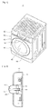
- Fig. 1 is a perspective view illustrating a conventional drum type washing machine A, which includes a cabinet having a front cover 100.
- the washing machine A has a large door 110 coupled to a front central region of the front cover 100.
- the door 110 is selectively openable to permit a user to input or output laundry therethrough, and to allow a user to confirm a washing state of the laundry.
- a detergent drawer 120 is provided that is capable of being drawn out forward at one side of an upper portion of the washing machine to contain detergent and laundering additives such as fabric softener.
- the washing machine A is provided with a plurality of buttons 140 for selecting and controlling functions and operations of the washing machine A, a control button 150 for selecting one of various washing cycles, and a control panel 130 which includes a display device 160 for displaying the washing state of the laundry.
- a printed circuit board (not shown) is coupled to the rear side of the control panel 130, and includes a rotary switch (not shown) capable of being rotated through manipulation of the control button 150 and other components.
- the printed circuit board is an electronic component that is connected to a microcomputer for controlling the operation of the washing machine, and receives input signals relating to the washing cycles or provides signals relating to the washing states.
- Fig. 2 is a cross-sectional view illustrating a coupled state of the control button and the printed circuit board of the conventional washing machine.
- the printed circuit board 170 attached to the rear side of the control panel 130 has a rotary switch 180 that is an electronic component for selectively inputting one of the various washing cycles, such as a standard cycle, wool/lingerie cycles, and the like.
- the control button 150 for manipulating the rotary switch 180 is coupled to one end of the rotary switch 180 outside the control panel 130.
- the control button 150 includes a body 152 protruding from the control panel130, and a fastening part 154 integral to the rear side of the body 152 and coupled to the rotary switch 180.
- the UK Patent Application GB 2 236 380 A describes a retractable operating knob for washing machine comprising a cylindrical button adjusting part provided on the control panel, a button securing part including a securing body having a fitting hole formed at its center, a button operating part including an operating body and an operating portion open at one end and having an operating through, and an elastic member having one end mounted to the operating portion, and the other end mounted to the button securing part, whereby said operating body is press-fitted into said button adjusting part.
- control button Since the body of the control button protrudes from the control panel, however, it is possible to inadvertently change the selected washing cycle through accidental contact with the control button. Moreover, the control button can be damaged in the event where the contact causes a large impact to the control button.
- the present invention is conceived to solve the problems of the conventional techniques as described above, and an aspect of the present invention is to provide a control button of a drum type washing machine that can be retracted inside a control panel after use of the control button or when manipulation thereof is not required.
- a control button of a drum type washing machine of a control panel for manipulating a rotary switch comprising: a button securing part, including a securing body having a fitting hole formed at the a center of the securing body, a securing portion extending from one side of the securing body and having a rack formed on an outer surface of the securing portion, and a coupling hole formed inside the securing portion so as to be in communication with the fitting hole inside the securing portion, and the coupling hole being coupled to the rotary switch; a button operating part, including an operating portion opened at one side end and having an operating trough and a pinion corresponding to the rack disposed inside the operating portion, a guide member disposed at one side of the operating portion, and an operating body integral to one side end of the guide member and to an opposed end of the operating portion; an elastic member having one end mounted between the operating body and the operating portion,
- the guide member comprises: a guide protruding piece formed at one side of an outer peripheral surface of the operating portion and having a guide-piece guiding portion defined therein; a guide-piece controlling protrusion formed on the guide-piece guiding portion to which divides the guide-piece guiding portion, and the guide-piece controlling protrusion including a guide groove facing which faces the operating body, the guide groove and having a V-shape such that the guide groove comprises a first slope and a second slope; and the a guide-piece having a moving end and a fixed end, the movingone end capable of moving along the guide-piece guiding portion to control operation of the button operating part, and the fixed end secured at the other end to the button securing part.
- the guide-piece controlling protrusion has a corner facing the guide guide-piece and biased to one side from of an imaginary straight line extending along a longitudinal axis of the guide-piecefrom a center of the guide piece.
- the guide member comprises a secondary guide-piece controlling protrusion formed on a surface of the operating portion so as to contact contacting the operating body, while facing the guide groove.
- the secondary guide-piece controlling protrusion has a corner facing the guide groove and biased to one side from an imaginary straight line extending from a center of the guide groove.
- the first slope of the guide groove is longer than the second slope.
- the button securing part, the button operating part, and the button adjusting part are made from a metallic material.
- the button securing part, the button operating part, and the button adjusting part are made from a synthetic resin
- the rack cooperatively engages the pinion such that: the securing portion is coupled to the operating portion; and the speed of the relative motion between the securing portion and the operating portion is governed.
- control panel forms a portion of a cabinet of a washing machine such that the rotary switch permits selection of a washing cycle from a plurality of washing cycles.
- a control button which manipulates a rotary switch, the rotary switch mounted to a printed circuit board disposed within a control panel
- the control button comprising: a button securing part mounted on the control button to the printed circuit board; a button operating part mounted on the button securing part and configured to move relative to the button securing part in a direction normal to the printed circuit board between a retracted position and an extended position; an elastic member disposed between the operating body and the operating portion arranged to bias the button operating part to the extended position; and a cylindrical button adjusting part provided on the control panel, the button adjusting part comprising an annular wall and a closed end which define a button adjusting part interior space, wherein the button operating part is press fit into the button adjusting part interior space, and the annular wall resides within an opening formed in the control panel such that the closed end is substantially flush with a surface of the control panel when the control button is in the retracted position, and the closed end is positioned outwardly of the surface
- the button securing part comprises an elongate guide piece
- the button operating part comprises a guiding portion
- the guiding portion comprising a guidepiece controlling protrusion disposed at one end of the guiding portion, the guide piece moves within the guiding portion, and the button operating part is maintained in the retracted position relative to the button securing part through engagement of the guide piece with the guide-piece controlling protrusion.
- control button of the drum type washing machine can be retracted inside the control panel after use of the control button or when manipulation thereof is not required, thereby preventing unwanted manipulation of the control button, which can occur during use of the washing machine.
- this construction it is possible to prevent in advance an unintended change in a washing cycle.
- the control button can be received inside the control panel, it is possible to prevent damage of the control button due to an accidental contact with external things.
- control button of the present invention can be applied to any kind of electronic appliance to prevent unwanted manipulation of the control button. Therefore, the scope of the present invention should be limited only by the accompanying claims.
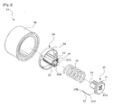
- the control button 10 of the drum type washing machine comprises a button securing part 20, a button operating part 30, an elastic member 40, and a button adjusting part 50.
- the button securing part 20 is to be coupled to a rotary switch 60 disposed on a printed circuit board 80, and generally comprises a securing body 21, a securing portion 22 and a coupling hole 26.
- the securing body 21 has a circular shape, and fitting hole 21A is formed at the center thereof.
- the securing portion 22 extends from one side of the securing body 21 and has a rack 23 formed on an outer surface of the securing portion 22.
- the securing portion 22 has a plurality of securing hooks 25 formed on an outer peripheral surface of one end of the securing portion 22, and, the rack 23 is engaged with a pinion 38 described below and serves to reduce the speed of the control button 10 when the control button 10 is inserted into or protruded from a control panel 90.
- the coupling hole 26 is in communication with the fitting hole 21A inside the securing portion 22 and is coupled to the rotary switch 60.
- the button operating part 30 is to be coupled to one side of the button securing part 20, and comprises an operating portion 31, a guide member 32 and an operating body 39.
- the operating portion 31 has an operating trough 31A formed therein, and a pinion 38 mounted within the operating trough 31A so as to be engaged with the rack 23, whereby the securing portion 22 of the button securing part 20 is coupled to the operating portion 31. Further, the operating portion 31 is open at one end thereof. Specifically, the open end of the operating portion 31 faces the button securing part 20.
- the guide member 32 is formed along one side of the operating portion 31, and the operating body 39 is integral to one end of the guide member 32, and to an end of the operating portion 31 that is opposed to the open end.
- Latch hooks 31B corresponding to the securing hooks 25 are formed on an inner peripheral surface at an inlet side of the operating trough 31A of the operating portion 31.
- the latch hooks 31B cooperatively engage the securing hooks 25 to prevent separation of the button operating part 30 from the button securing part 20.
- the guide member 32 generally comprises a guide protruding piece 33, a guide-piece controlling protrusion 35, a secondary guide-piece controlling protrusion 35A, and a guide piece 37.
- the guide piece 37 is an elongate, generally U-shaped member having a fixed end 37A and a movable end 37B.
- the guide protruding piece 33 extends integrally on one side of an outer peripheral surface of the operating portion 31 in the longitudinal direction and has a guide-piece guiding portion 34 defined therein.
- the guide-piece controlling protrusion 35 is formed on the guide-piece guiding portion 34 to divide the guide-piece guiding portion 34 to a first guide section 34A and a second guide section 34B.
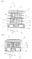
- the first guide section 34A indicates a first side (for example, the right side) of the guide-piece guiding portion 34 (see Fig. 5 ) and constitutes a passage along which the control button 10 moves when being inserted into the control panel 90.
- the second guide section 34B indicates a second side (for example, the left side) of the guide-piece guiding portion 34 and constitutes a passage along which the control button 10 moves when being extended from within the control panel 90.
- the guide-piece controlling protrusion 35 has a leading corner located at one side (for example, a left side) of an imaginary straight line extending along a longitudinal axis of the guide piece 37, the movable end 37B of the guide piece 37 is guided toward the first guide section 34A by the leading corner of the guide-piece controlling protrusion 35 when the button adjusting part 50 is inserted into the control panel 90.
- the guide-piece controlling protrusion 35 is formed with a V-shaped guide groove 36 that faces the operating body 39 and is divided into a first slope 36A and a second slope 36B.
- the first slope 36A indicates a right side of the guide groove 36 (see Fig. 5 ).
- the second slope 36B indicates a left side of the guide groove 36.
- the first slope 36A of the guide groove 36 is longer than the second slope 36B to allow the movable end 37B of the guide piece 37 located on the guide groove 36 to be easily released from the guide groove 36 to permit operation of the button operating part 30 when using the washing machine.
- the secondary guide-piece controlling protrusion 35A is formed on one side of the operating portion 31 contacting the operating body 39 and faces the guide groove 36 to allow the movable end 37B to be easily released from the guide groove 36.
- the secondary guide-piece controlling protrusion 35A has a triangular shape, in which, assuming one side contacting the one side of the operating portion 31 is a base, another side perpendicular to the base is a height side, and the third side is a hypotenuse, a corner where the height side meets the hypotenuse is formed at a location biased to the first slope 36A side from an imaginary straight line extending from the center of the guide groove 36.
- the fixed end 37A of the guide piece 37 is secured to the button securing part 20 such that the movable end 37B can control the operation of the button operating part 30 while moving along the guide-piece guiding portion 34, the first guide section 34A, the second guide section 34B, and the like.
- the elastic member 40 has one end mounted between the operating body 39 and the operating portion 31, and the other end mounted on the securing body 21 of the button securing part 20.
- the elastic member 40 becomes compressed.
- the button operating part 30 is moved in a direction where restoration of the compressed elastic member 40 occurs, thereby allowing the control button 10 to extend outward relative to the control panel 90.
- the button adjusting part 50 is provided to the control panel 90, and has a cylindrical shape, of which one end 52 is closed and the other end 56 is open.
- the operating body 39 of the button operating part 30 is press-fitted into the open end 56 of the button adjusting portion 50.
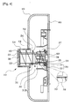
- the annular wall portion 54 of the button adjusting part 50 resides within an inserting hole 92 formed in the control panel 90 such that the closed end 52 is substantially flush with a surface of the control panel 90 when the control button 10 is in the retracted position, and the closed end 52 is positioned outwardly of the surface of the control panel 90 ( Fig. 4 ) when the control button 10 is in the extended position.
- the button securing part 20, button operating part 30 and button adjusting part 50 are made from a metallic material or a synthetic resin
- the control button 10 of the drum type washing machine is coupled to the rotary switch 60 disposed on the printed circuit board 80 through the inserting hole 92 of the control panel 90. Then, when a user rotates the control button 10 toward a mark indicating a certain washing cycle among various washing cycles, the rotary switch 60 will be rotated by the rotation of the control button 10.
- the rotary switch 60 is provided for selectively inputting one of the various washing cycles, such as a standard cycle, wool/lingerie cycles, etc., to the printed circuit board 80, and enables the washing machine to perform the washing cycle selected by the user.
- the button operating part 30 When the inserted button adjusting part 50 of the control button 10 is pressed, the button operating part 30 is moved inward by the compressive force to the button adjusting part 50. Then, the movable end 37B of the guide piece 37 located in the guide groove 36 is moved to the secondary guide-piece controlling protrusion 35A, and is guided to the second guide section 34B along the hypotenuse of the secondary guide-piece controlling protrusion 35A.
- the movable end 37B When the movable end 37B is released from the guide groove 36, the elastic member 40, which has been compressed between the button operating part 30 and the button securing part 20, is restored to its original state, and the button operating part 30 moves away from the button securing part 20. At this time, the movable end 37B is located at the other end of the guide protruding piece 33 after being moved along the second guide section 34B and the guide-piece guiding portion 34, and the button adjusting part 50 protrudes from the control panel 90 (see Fig. 5 ).
- the button operating part 30 spaced from the button securing part 20 is not completely separated from button securing part 20 since the latch hooks 31B of the button operating part 30 are latched to the securing hooks 25 of the button securing part 20.
- the user operates the washing machine to perform a selected washing cycle by rotating the control button 10 toward the selected washing cycle.
- control button 10 the user pushes the control button 10 again to make the button adjusting part 50 retract into the control panel 90.
- the button operating part 30 when pushing the button adjusting part 50 of the control button 10 while it is protruding from the control panel 90, the button operating part 30 is moved toward the button securing part 20 by the compressive pushing force applied to the button adjusting part 50.
- the movable end 37B of the guide piece 37 is moved to the first guide section 34A from the guide-piece guiding portion 34.
- the movable end 37B is guided to the first slope 36A of the guide groove 36 after moving along the first guide section 34A, and when the button adjusting part 50 is released, the movable end 37B is located and stopped at the center of the guide groove 36. That is, movable end 37B is located and stopped between the first slope 36A and the second slope 36B by the restoration force of the elastic member 40, after moving along the first slope 36A of the guide-piece controlling protrusion 35.
- the separation between the button securing part 20 and the button operating part 30 is narrowed, and the button adjusting part 50 is retracted into the control panel 90 through the inserting hole 92 of the control panel 90, so that the button adjusting part 50 does not protrude from the control panel 90 (see Fig. 6 ).
- the configurations of the rack 23 formed on the button securing part 20 and the pinion 38 formed on the button operating part 30 corresponding to the rack 23 enable retraction and extension of the control button 10 with respect to the control panel to be performed more smoothly.
- the rack 23 and the pinion 38 it is possible to prevent reduction in coupling force between the button coupling part 20 and the button operating part 30, which can be caused by an accidental retraction or extension of the control button 10, while improving operating sensations experienced by the user when the control button 10 is inserted into or protruded from the control panel 90.
Landscapes
- Engineering & Computer Science (AREA)
- Textile Engineering (AREA)
- Main Body Construction Of Washing Machines And Laundry Dryers (AREA)
- Detail Structures Of Washing Machines And Dryers (AREA)
Claims (10)
- Bedienungsknopf (10) eines Bedienungsfeldes zum Betätigen eines Drehschalters (60), wobei der Bedienungsknopf (10) aufweist:einen Knopfbefestigungsteil (20), einen Knopfbetätigungsteil (30) und ein elastisches Bauteil (40), wobeider Knopfbefestigungsteil (20) aufweist:einen Befestigungskörper (21), der ein Einpassloch (21A) aufweist, das an einer Mitte des Befestigungskörpers (21) ausgebildet ist,einen Befestigungsanteil (22), der sich von einer Seite des Befestigungskörpers (21) aus erstreckt und eine Zahnstange (23) aufweist, die auf einer Außenfläche des Befestigungsanteils (22) ausgebildet ist, undein Kopplungsloch (26), das so innen im Befestigungsanteil (22) ausgebildet ist, dass es in Verbindung mit dem Einpassloch (21A) steht, wobei das Kopplungsloch (26) an den Drehschalter (60) gekoppelt ist;der Knopfbetätigungsteil (30) aufweist:einen Betätigungsanteil (31), der an einem Ende offen ist und eine Betätigungsrinne (31A) und ein zur Zahnstange (23) zugehöriges Antriebsritzel (38) aufweist, das innen im Betätigungsanteil (31) angeordnet ist,ein Führungsbauteil (32), das an einer Seite des Betätigungsanteils (31) angeordnet ist, undeinen Betätigungskörper (39), der fest mit einem Ende des Führungsbauteils (32) und mit einem gegenüberliegenden Ende des Betätigungsanteils (31) verbunden ist; unddas elastische Bauteil (40) ein Ende aufweist, das zwischen dem Betätigungskörper (39) und dem Betätigungsanteil (31) befestigt ist, und wobei das andere Ende auf dem Knopfbefestigungsteil (20) befestigt ist; undein zylindrischer Knopfeinstellteil (50) auf dem Bedienungsfeld (90) vorgesehen ist und wobei der Betätigungskörper (39) in den Knopfeinstellteil (50) eingepasst ist.
- Bedienungsknopf (10) nach Anspruch 1, wobei das Führungsbauteil (32) aufweist:ein Führungsvorwölbungsstück (33), das an einer Seite einer Außenumfangsfläche des Betätigungsanteils (31) ausgebildet ist und einen darin festgelegten Führungsstück-Lenkungsanteil (34) aufweist;eine Führungsstück-Steuerungsvorwölbung (35), die auf dem Führungsstück-Lenkungsanteil (34) ausgebildet ist, welche den Führungsstück-Lenkungsanteil (34) aufteilt, wobei die Führungsstück-Steuerungsvorwölbung (35) eine Führungsnut aufweist, die dem Betätigungskörper (39) gegenüberliegt, wobei die Führungsnut (36) eine V-Form derart aufweist, dass die Führungsnut (36) eine erste Flanke (36A) und eine zweite Flanke (36B) aufweist; undein Führungsstück (37), das ein sich bewegendes Ende (37B) und ein fixiertes Ende (37A) aufweist, wobei das sich bewegende Ende (37B) in der Lage ist, sich entlang des Führungsstück-Lenkungsanteils (34) zu bewegen, um die Betätigung des Knopfbetätigungsteils (30) zu steuern, und das fixierte Ende am Knopfbefestigungsteil (20) befestigt ist.
- Bedienungsknopf (10) nach Anspruch 2, wobei die Führungsstück-Steuerungsvorwölbung (35) eine Ecke aufweist, die dem Führungsstück (37) gegenüberliegt und zu einer Seite einer imaginären geraden Linie voreingestellt ist, die sich entlang einer Längsachse des Führungsstücks (37) erstreckt.
- Bedienungsknopf (10) nach Anspruch 2, wobei das Führungsbauteil (32) eine sekundäre Führungsstück-Steuerungsvorwölbung (35A) aufweist, die auf einer Fläche des Betätigungsanteils (31) so ausgebildet ist, dass sie den Betätigungskörper (39) kontaktiert, während sie der Führungsnut (36) gegenüberliegt.
- Bedienungsknopf (10) nach Anspruch 4, wobei die sekundäre Führungsstück-Steuerungsvorwölbung (35A) eine Ecke aufweist, die der Führungsnut (36) gegenüberliegt und die zu einer Seite von einer imaginären geraden Linie voreingestellt ist, die sich von einer Mitte der Führungsnut (36) aus erstreckt.
- Bedienungsknopf (10) nach Anspruch 2, wobei die erste Flanke (36A) der Führungsnut (36) länger als die zweite Flanke (36B) ist.
- Bedienungsknopf (10) nach Anspruch 1, wobei der Knopfbefestigungsteil (20), der Knopfbetätigungsteil (30) und der Knopfeinstellteil (50) aus einem metallischen Material bestehen.
- Bedienungsknopf (10) nach Anspruch 1, wobei der Knopfbefestigungsteil (20), der Knopfbetätigungsteil (30) und der Knopfeinstellteil (50) aus Kunstharz bestehen.
- Bedienungsknopf (10) nach Anspruch 1, wobei die Zahnstange (23) zusammenwirkend derart an dem Antriebsritzel (38) angreift, dass:der Befestigungsanteil (22) an den Betätigungsanteil (31) angekoppelt ist; unddie Geschwindigkeit der Relativbewegung zwischen dem Befestigungsanteil (22) und dem Betätigungsanteil (31) reguliert wird.
- Bedienungsknopf (10) nach Anspruch 1, wobei das Bedienungsfeld (90) einen Anteil eines Gehäuses einer Waschmaschine derart bildet, dass der Drehschalter (60) eine Auswahl eines Waschzyklus aus mehreren Waschzyklen erlaubt.
Applications Claiming Priority (2)
| Application Number | Priority Date | Filing Date | Title |
|---|---|---|---|
| KR1020060131337A KR100838566B1 (ko) | 2006-12-20 | 2006-12-20 | 드럼 세탁기의 컨트롤 버튼 |
| PCT/KR2007/006434 WO2008075850A1 (en) | 2006-12-20 | 2007-12-11 | Control button of drum type washing machine |
Publications (3)
| Publication Number | Publication Date |
|---|---|
| EP2118359A1 EP2118359A1 (de) | 2009-11-18 |
| EP2118359A4 EP2118359A4 (de) | 2010-09-29 |
| EP2118359B1 true EP2118359B1 (de) | 2014-03-26 |
Family
ID=39536437
Family Applications (1)
| Application Number | Title | Priority Date | Filing Date |
|---|---|---|---|
| EP07851405.6A Not-in-force EP2118359B1 (de) | 2006-12-20 | 2007-12-11 | Bedienungsknopf für eine trommelwaschmaschine |
Country Status (6)
| Country | Link |
|---|---|
| US (1) | US7582841B2 (de) |
| EP (1) | EP2118359B1 (de) |
| JP (1) | JP4892064B2 (de) |
| KR (1) | KR100838566B1 (de) |
| CN (1) | CN101563494B (de) |
| WO (1) | WO2008075850A1 (de) |
Families Citing this family (4)
| Publication number | Priority date | Publication date | Assignee | Title |
|---|---|---|---|---|
| DE10319383A1 (de) * | 2003-04-30 | 2004-11-18 | Delphi Technologies, Inc., Troy | Elektrischer Drehschalter |
| KR101212693B1 (ko) | 2006-08-25 | 2012-12-14 | 엘지전자 주식회사 | 전기전자기기의 컨트롤러 |
| KR20180136105A (ko) * | 2017-06-14 | 2018-12-24 | 주식회사 대우전자 | 벽걸이형 세탁기 및 그의 도어 개폐 장치 |
| KR102642746B1 (ko) * | 2023-06-27 | 2024-03-05 | 윤석중 | 세탁기 도어 잠금장치 |
Family Cites Families (12)
| Publication number | Priority date | Publication date | Assignee | Title |
|---|---|---|---|---|
| JPH035625A (ja) * | 1989-05-30 | 1991-01-11 | Toshiba Corp | 調理器の操作装置 |
| JPH03111100A (ja) * | 1989-09-25 | 1991-05-10 | Toshiba Corp | 洗濯機 |
| JPH0449995A (ja) | 1990-06-14 | 1992-02-19 | Toshiba Corp | 洗濯機 |
| JP3075587B2 (ja) * | 1991-06-13 | 2000-08-14 | 花王株式会社 | 錠剤型洗剤自動投入装置付洗濯機 |
| FR2698459B1 (fr) * | 1992-11-20 | 1994-12-30 | Renault | Bouton escamotable de commande d'un arbre support tournant. |
| JPH0763337A (ja) | 1993-08-27 | 1995-03-07 | Toshiba Corp | 加熱調理器 |
| TR199600723A2 (xx) * | 1996-09-12 | 1998-04-21 | Ar�El�K A.�. | Ev aletlerinde kullan�lan kontrol d��mesi. |
| JP3810901B2 (ja) * | 1997-09-05 | 2006-08-16 | 株式会社東芝 | 加熱調理器 |
| EP1526422B1 (de) * | 2003-10-22 | 2007-02-14 | Lisi Automotive Rapid | Versenkbare Drehgriffvorrichtung einer Schalt-oder Stelleinrichtung insbesondere eines Haushaltsgeräts |
| JP4319890B2 (ja) * | 2003-10-31 | 2009-08-26 | アルプス電気株式会社 | 複合操作機構 |
| SE0403219D0 (sv) * | 2004-12-30 | 2004-12-30 | Electrolux Ab | Control knob assembly |
| KR100730938B1 (ko) * | 2005-04-27 | 2007-06-22 | 주식회사 대우일렉트로닉스 | 드럼 세탁기용 다이얼 버튼 |
-
2006
- 2006-12-20 KR KR1020060131337A patent/KR100838566B1/ko not_active Expired - Fee Related
-
2007
- 2007-12-11 WO PCT/KR2007/006434 patent/WO2008075850A1/en not_active Ceased
- 2007-12-11 EP EP07851405.6A patent/EP2118359B1/de not_active Not-in-force
- 2007-12-11 CN CN2007800466851A patent/CN101563494B/zh not_active Expired - Fee Related
- 2007-12-11 JP JP2009542634A patent/JP4892064B2/ja not_active Expired - Fee Related
- 2007-12-19 US US11/959,884 patent/US7582841B2/en not_active Expired - Fee Related
Also Published As
| Publication number | Publication date |
|---|---|
| CN101563494A (zh) | 2009-10-21 |
| JP2010512935A (ja) | 2010-04-30 |
| EP2118359A1 (de) | 2009-11-18 |
| US20080148787A1 (en) | 2008-06-26 |
| WO2008075850A1 (en) | 2008-06-26 |
| EP2118359A4 (de) | 2010-09-29 |
| JP4892064B2 (ja) | 2012-03-07 |
| CN101563494B (zh) | 2011-11-30 |
| KR100838566B1 (ko) | 2008-06-19 |
| US7582841B2 (en) | 2009-09-01 |
Similar Documents
| Publication | Publication Date | Title |
|---|---|---|
| US8438878B2 (en) | Control unit of laundry processing apparatus | |
| US7582841B2 (en) | Control button of drum type washing machine | |
| EP2876197A1 (de) | Waschmaschine mit Schubladenanordnung | |
| KR20140073907A (ko) | 세탁기의 세제케이스 잠금장치 | |
| KR20060000180A (ko) | 컴퓨터 | |
| KR20150109817A (ko) | 의류처리장치 | |
| EP3067458A1 (de) | Waschmittelschalenanordnung für waschmaschine und waschmaschine | |
| CN113106706B (zh) | 衣物处理装置 | |
| US7265309B2 (en) | Button assembly of control panel assembly | |
| EP2889419B1 (de) | Waschmaschine | |
| JP3813832B2 (ja) | 洗濯機の蓋ロック装置 | |
| KR20080058300A (ko) | 드럼 세탁기의 컨트롤 버튼 | |
| CN211848533U (zh) | 洗衣机 | |
| KR100730938B1 (ko) | 드럼 세탁기용 다이얼 버튼 | |
| EP2832917B1 (de) | Waschmaschine mit Schubladenanordnung | |
| US12497725B2 (en) | Washing machine | |
| JP7073040B2 (ja) | 衣類処理装置 | |
| KR20020036146A (ko) | 드럼세탁기의 도어 개폐장치 | |
| CN107407035B (zh) | 洗衣机 | |
| KR20080023444A (ko) | 세탁 장치 | |
| KR20060120915A (ko) | 세탁기의 조작버튼 설치구조 | |
| JP2019024744A (ja) | ドラム式洗濯機 | |
| KR100784719B1 (ko) | 개폐식 조작부 및 이를 구비하는 세탁기 | |
| KR20230001299A (ko) | 의류처리장치 | |
| KR20030073062A (ko) | 드럼세탁기에 있어서의 컨트롤패널의 버튼 조립구조 |
Legal Events
| Date | Code | Title | Description |
|---|---|---|---|
| PUAI | Public reference made under article 153(3) epc to a published international application that has entered the european phase |
Free format text: ORIGINAL CODE: 0009012 |
|
| 17P | Request for examination filed |
Effective date: 20090703 |
|
| AK | Designated contracting states |
Kind code of ref document: A1 Designated state(s): AT BE BG CH CY CZ DE DK EE ES FI FR GB GR HU IE IS IT LI LT LU LV MC MT NL PL PT RO SE SI SK TR |
|
| DAX | Request for extension of the european patent (deleted) | ||
| A4 | Supplementary search report drawn up and despatched |
Effective date: 20100826 |
|
| GRAP | Despatch of communication of intention to grant a patent |
Free format text: ORIGINAL CODE: EPIDOSNIGR1 |
|
| INTG | Intention to grant announced |
Effective date: 20131009 |
|
| GRAS | Grant fee paid |
Free format text: ORIGINAL CODE: EPIDOSNIGR3 |
|
| GRAA | (expected) grant |
Free format text: ORIGINAL CODE: 0009210 |
|
| AK | Designated contracting states |
Kind code of ref document: B1 Designated state(s): AT BE BG CH CY CZ DE DK EE ES FI FR GB GR HU IE IS IT LI LT LU LV MC MT NL PL PT RO SE SI SK TR |
|
| REG | Reference to a national code |
Ref country code: GB Ref legal event code: FG4D |
|
| REG | Reference to a national code |
Ref country code: CH Ref legal event code: EP |
|
| REG | Reference to a national code |
Ref country code: AT Ref legal event code: REF Ref document number: 659079 Country of ref document: AT Kind code of ref document: T Effective date: 20140415 |
|
| REG | Reference to a national code |
Ref country code: IE Ref legal event code: FG4D |
|
| REG | Reference to a national code |
Ref country code: DE Ref legal event code: R096 Ref document number: 602007035815 Country of ref document: DE Effective date: 20140508 |
|
| PG25 | Lapsed in a contracting state [announced via postgrant information from national office to epo] |
Ref country code: LT Free format text: LAPSE BECAUSE OF FAILURE TO SUBMIT A TRANSLATION OF THE DESCRIPTION OR TO PAY THE FEE WITHIN THE PRESCRIBED TIME-LIMIT Effective date: 20140326 |
|
| REG | Reference to a national code |
Ref country code: AT Ref legal event code: MK05 Ref document number: 659079 Country of ref document: AT Kind code of ref document: T Effective date: 20140326 |
|
| REG | Reference to a national code |
Ref country code: NL Ref legal event code: VDEP Effective date: 20140326 |
|
| REG | Reference to a national code |
Ref country code: LT Ref legal event code: MG4D |
|
| PG25 | Lapsed in a contracting state [announced via postgrant information from national office to epo] |
Ref country code: SE Free format text: LAPSE BECAUSE OF FAILURE TO SUBMIT A TRANSLATION OF THE DESCRIPTION OR TO PAY THE FEE WITHIN THE PRESCRIBED TIME-LIMIT Effective date: 20140326 Ref country code: FI Free format text: LAPSE BECAUSE OF FAILURE TO SUBMIT A TRANSLATION OF THE DESCRIPTION OR TO PAY THE FEE WITHIN THE PRESCRIBED TIME-LIMIT Effective date: 20140326 |
|
| PG25 | Lapsed in a contracting state [announced via postgrant information from national office to epo] |
Ref country code: LV Free format text: LAPSE BECAUSE OF FAILURE TO SUBMIT A TRANSLATION OF THE DESCRIPTION OR TO PAY THE FEE WITHIN THE PRESCRIBED TIME-LIMIT Effective date: 20140326 |
|
| PG25 | Lapsed in a contracting state [announced via postgrant information from national office to epo] |
Ref country code: BE Free format text: LAPSE BECAUSE OF FAILURE TO SUBMIT A TRANSLATION OF THE DESCRIPTION OR TO PAY THE FEE WITHIN THE PRESCRIBED TIME-LIMIT Effective date: 20140326 Ref country code: BG Free format text: LAPSE BECAUSE OF FAILURE TO SUBMIT A TRANSLATION OF THE DESCRIPTION OR TO PAY THE FEE WITHIN THE PRESCRIBED TIME-LIMIT Effective date: 20140626 Ref country code: EE Free format text: LAPSE BECAUSE OF FAILURE TO SUBMIT A TRANSLATION OF THE DESCRIPTION OR TO PAY THE FEE WITHIN THE PRESCRIBED TIME-LIMIT Effective date: 20140326 Ref country code: CZ Free format text: LAPSE BECAUSE OF FAILURE TO SUBMIT A TRANSLATION OF THE DESCRIPTION OR TO PAY THE FEE WITHIN THE PRESCRIBED TIME-LIMIT Effective date: 20140326 Ref country code: IS Free format text: LAPSE BECAUSE OF FAILURE TO SUBMIT A TRANSLATION OF THE DESCRIPTION OR TO PAY THE FEE WITHIN THE PRESCRIBED TIME-LIMIT Effective date: 20140726 Ref country code: CY Free format text: LAPSE BECAUSE OF FAILURE TO SUBMIT A TRANSLATION OF THE DESCRIPTION OR TO PAY THE FEE WITHIN THE PRESCRIBED TIME-LIMIT Effective date: 20140326 Ref country code: RO Free format text: LAPSE BECAUSE OF FAILURE TO SUBMIT A TRANSLATION OF THE DESCRIPTION OR TO PAY THE FEE WITHIN THE PRESCRIBED TIME-LIMIT Effective date: 20140326 Ref country code: NL Free format text: LAPSE BECAUSE OF FAILURE TO SUBMIT A TRANSLATION OF THE DESCRIPTION OR TO PAY THE FEE WITHIN THE PRESCRIBED TIME-LIMIT Effective date: 20140326 |
|
| PG25 | Lapsed in a contracting state [announced via postgrant information from national office to epo] |
Ref country code: AT Free format text: LAPSE BECAUSE OF FAILURE TO SUBMIT A TRANSLATION OF THE DESCRIPTION OR TO PAY THE FEE WITHIN THE PRESCRIBED TIME-LIMIT Effective date: 20140326 Ref country code: PL Free format text: LAPSE BECAUSE OF FAILURE TO SUBMIT A TRANSLATION OF THE DESCRIPTION OR TO PAY THE FEE WITHIN THE PRESCRIBED TIME-LIMIT Effective date: 20140326 Ref country code: ES Free format text: LAPSE BECAUSE OF FAILURE TO SUBMIT A TRANSLATION OF THE DESCRIPTION OR TO PAY THE FEE WITHIN THE PRESCRIBED TIME-LIMIT Effective date: 20140326 Ref country code: SK Free format text: LAPSE BECAUSE OF FAILURE TO SUBMIT A TRANSLATION OF THE DESCRIPTION OR TO PAY THE FEE WITHIN THE PRESCRIBED TIME-LIMIT Effective date: 20140326 |
|
| PG25 | Lapsed in a contracting state [announced via postgrant information from national office to epo] |
Ref country code: PT Free format text: LAPSE BECAUSE OF FAILURE TO SUBMIT A TRANSLATION OF THE DESCRIPTION OR TO PAY THE FEE WITHIN THE PRESCRIBED TIME-LIMIT Effective date: 20140728 |
|
| REG | Reference to a national code |
Ref country code: DE Ref legal event code: R097 Ref document number: 602007035815 Country of ref document: DE |
|
| PG25 | Lapsed in a contracting state [announced via postgrant information from national office to epo] |
Ref country code: DK Free format text: LAPSE BECAUSE OF FAILURE TO SUBMIT A TRANSLATION OF THE DESCRIPTION OR TO PAY THE FEE WITHIN THE PRESCRIBED TIME-LIMIT Effective date: 20140326 |
|
| PLBE | No opposition filed within time limit |
Free format text: ORIGINAL CODE: 0009261 |
|
| STAA | Information on the status of an ep patent application or granted ep patent |
Free format text: STATUS: NO OPPOSITION FILED WITHIN TIME LIMIT |
|
| 26N | No opposition filed |
Effective date: 20150106 |
|
| PG25 | Lapsed in a contracting state [announced via postgrant information from national office to epo] |
Ref country code: IT Free format text: LAPSE BECAUSE OF FAILURE TO SUBMIT A TRANSLATION OF THE DESCRIPTION OR TO PAY THE FEE WITHIN THE PRESCRIBED TIME-LIMIT Effective date: 20140326 |
|
| REG | Reference to a national code |
Ref country code: DE Ref legal event code: R097 Ref document number: 602007035815 Country of ref document: DE Effective date: 20150106 |
|
| PG25 | Lapsed in a contracting state [announced via postgrant information from national office to epo] |
Ref country code: LU Free format text: LAPSE BECAUSE OF FAILURE TO SUBMIT A TRANSLATION OF THE DESCRIPTION OR TO PAY THE FEE WITHIN THE PRESCRIBED TIME-LIMIT Effective date: 20141211 Ref country code: SI Free format text: LAPSE BECAUSE OF FAILURE TO SUBMIT A TRANSLATION OF THE DESCRIPTION OR TO PAY THE FEE WITHIN THE PRESCRIBED TIME-LIMIT Effective date: 20140326 |
|
| REG | Reference to a national code |
Ref country code: CH Ref legal event code: PL |
|
| REG | Reference to a national code |
Ref country code: IE Ref legal event code: MM4A |
|
| PG25 | Lapsed in a contracting state [announced via postgrant information from national office to epo] |
Ref country code: IE Free format text: LAPSE BECAUSE OF NON-PAYMENT OF DUE FEES Effective date: 20141211 Ref country code: CH Free format text: LAPSE BECAUSE OF NON-PAYMENT OF DUE FEES Effective date: 20141231 Ref country code: LI Free format text: LAPSE BECAUSE OF NON-PAYMENT OF DUE FEES Effective date: 20141231 |
|
| REG | Reference to a national code |
Ref country code: FR Ref legal event code: PLFP Year of fee payment: 9 |
|
| PG25 | Lapsed in a contracting state [announced via postgrant information from national office to epo] |
Ref country code: MC Free format text: LAPSE BECAUSE OF FAILURE TO SUBMIT A TRANSLATION OF THE DESCRIPTION OR TO PAY THE FEE WITHIN THE PRESCRIBED TIME-LIMIT Effective date: 20140326 |
|
| PG25 | Lapsed in a contracting state [announced via postgrant information from national office to epo] |
Ref country code: GR Free format text: LAPSE BECAUSE OF FAILURE TO SUBMIT A TRANSLATION OF THE DESCRIPTION OR TO PAY THE FEE WITHIN THE PRESCRIBED TIME-LIMIT Effective date: 20140627 |
|
| PG25 | Lapsed in a contracting state [announced via postgrant information from national office to epo] |
Ref country code: HU Free format text: LAPSE BECAUSE OF FAILURE TO SUBMIT A TRANSLATION OF THE DESCRIPTION OR TO PAY THE FEE WITHIN THE PRESCRIBED TIME-LIMIT; INVALID AB INITIO Effective date: 20071211 Ref country code: TR Free format text: LAPSE BECAUSE OF FAILURE TO SUBMIT A TRANSLATION OF THE DESCRIPTION OR TO PAY THE FEE WITHIN THE PRESCRIBED TIME-LIMIT Effective date: 20140326 Ref country code: MT Free format text: LAPSE BECAUSE OF FAILURE TO SUBMIT A TRANSLATION OF THE DESCRIPTION OR TO PAY THE FEE WITHIN THE PRESCRIBED TIME-LIMIT Effective date: 20140326 |
|
| REG | Reference to a national code |
Ref country code: FR Ref legal event code: PLFP Year of fee payment: 10 |
|
| REG | Reference to a national code |
Ref country code: FR Ref legal event code: PLFP Year of fee payment: 11 |
|
| PGFP | Annual fee paid to national office [announced via postgrant information from national office to epo] |
Ref country code: FR Payment date: 20171113 Year of fee payment: 11 Ref country code: DE Payment date: 20171206 Year of fee payment: 11 |
|
| PGFP | Annual fee paid to national office [announced via postgrant information from national office to epo] |
Ref country code: GB Payment date: 20171206 Year of fee payment: 11 |
|
| REG | Reference to a national code |
Ref country code: DE Ref legal event code: R119 Ref document number: 602007035815 Country of ref document: DE |
|
| GBPC | Gb: european patent ceased through non-payment of renewal fee |
Effective date: 20181211 |
|
| PG25 | Lapsed in a contracting state [announced via postgrant information from national office to epo] |
Ref country code: FR Free format text: LAPSE BECAUSE OF NON-PAYMENT OF DUE FEES Effective date: 20181231 Ref country code: DE Free format text: LAPSE BECAUSE OF NON-PAYMENT OF DUE FEES Effective date: 20190702 |
|
| PG25 | Lapsed in a contracting state [announced via postgrant information from national office to epo] |
Ref country code: GB Free format text: LAPSE BECAUSE OF NON-PAYMENT OF DUE FEES Effective date: 20181211 |