EP2117394B1 - Zugmittelantrieb für ein haushaltsgerät - Google Patents
Zugmittelantrieb für ein haushaltsgerät Download PDFInfo
- Publication number
- EP2117394B1 EP2117394B1 EP08701469A EP08701469A EP2117394B1 EP 2117394 B1 EP2117394 B1 EP 2117394B1 EP 08701469 A EP08701469 A EP 08701469A EP 08701469 A EP08701469 A EP 08701469A EP 2117394 B1 EP2117394 B1 EP 2117394B1
- Authority
- EP
- European Patent Office
- Prior art keywords
- drive
- pulley
- traction means
- shaft
- pivot axis
- Prior art date
- Legal status (The legal status is an assumption and is not a legal conclusion. Google has not performed a legal analysis and makes no representation as to the accuracy of the status listed.)
- Not-in-force
Links
- 238000010411 cooking Methods 0.000 abstract 1
- 230000005540 biological transmission Effects 0.000 description 4
- 238000004898 kneading Methods 0.000 description 3
- 238000010276 construction Methods 0.000 description 2
- 230000001419 dependent effect Effects 0.000 description 2
- 230000008878 coupling Effects 0.000 description 1
- 238000010168 coupling process Methods 0.000 description 1
- 238000005859 coupling reaction Methods 0.000 description 1
- 238000011161 development Methods 0.000 description 1
- 230000018109 developmental process Effects 0.000 description 1
- 230000002093 peripheral effect Effects 0.000 description 1
Images


Classifications
-
- F—MECHANICAL ENGINEERING; LIGHTING; HEATING; WEAPONS; BLASTING
- F16—ENGINEERING ELEMENTS AND UNITS; GENERAL MEASURES FOR PRODUCING AND MAINTAINING EFFECTIVE FUNCTIONING OF MACHINES OR INSTALLATIONS; THERMAL INSULATION IN GENERAL
- F16H—GEARING
- F16H7/00—Gearings for conveying rotary motion by endless flexible members
- F16H7/02—Gearings for conveying rotary motion by endless flexible members with belts; with V-belts
- F16H7/023—Gearings for conveying rotary motion by endless flexible members with belts; with V-belts with belts having a toothed contact surface or regularly spaced bosses or hollows for slipless or nearly slipless meshing with complementary profiled contact surface of a pulley
-
- A—HUMAN NECESSITIES
- A47—FURNITURE; DOMESTIC ARTICLES OR APPLIANCES; COFFEE MILLS; SPICE MILLS; SUCTION CLEANERS IN GENERAL
- A47J—KITCHEN EQUIPMENT; COFFEE MILLS; SPICE MILLS; APPARATUS FOR MAKING BEVERAGES
- A47J43/00—Implements for preparing or holding food, not provided for in other groups of this subclass
- A47J43/04—Machines for domestic use not covered elsewhere, e.g. for grinding, mixing, stirring, kneading, emulsifying, whipping or beating foodstuffs, e.g. power-driven
- A47J43/07—Parts or details, e.g. mixing tools, whipping tools
- A47J43/08—Driving mechanisms
-
- F—MECHANICAL ENGINEERING; LIGHTING; HEATING; WEAPONS; BLASTING
- F16—ENGINEERING ELEMENTS AND UNITS; GENERAL MEASURES FOR PRODUCING AND MAINTAINING EFFECTIVE FUNCTIONING OF MACHINES OR INSTALLATIONS; THERMAL INSULATION IN GENERAL
- F16H—GEARING
- F16H1/00—Toothed gearings for conveying rotary motion
- F16H1/02—Toothed gearings for conveying rotary motion without gears having orbital motion
- F16H1/04—Toothed gearings for conveying rotary motion without gears having orbital motion involving only two intermeshing members
- F16H1/06—Toothed gearings for conveying rotary motion without gears having orbital motion involving only two intermeshing members with parallel axes
- F16H1/10—Toothed gearings for conveying rotary motion without gears having orbital motion involving only two intermeshing members with parallel axes one of the members being internally toothed
-
- F—MECHANICAL ENGINEERING; LIGHTING; HEATING; WEAPONS; BLASTING
- F16—ENGINEERING ELEMENTS AND UNITS; GENERAL MEASURES FOR PRODUCING AND MAINTAINING EFFECTIVE FUNCTIONING OF MACHINES OR INSTALLATIONS; THERMAL INSULATION IN GENERAL
- F16H—GEARING
- F16H7/00—Gearings for conveying rotary motion by endless flexible members
- F16H7/08—Means for varying tension of belts, ropes or chains
- F16H7/10—Means for varying tension of belts, ropes or chains by adjusting the axis of a pulley
- F16H7/14—Means for varying tension of belts, ropes or chains by adjusting the axis of a pulley of a driving or driven pulley
Definitions
- the present invention relates to a traction mechanism drive for a household appliance, in particular for a food processor, according to the preamble of claim 1. It also relates to a food processor with the traction drive.
- a belt drive for a home electric motor device in which a arranged on the shaft of an electric motor pulley is connected via a belt with another pulley in drive connection.
- a tensioning disc engaging the belt is provided.
- the clamping disk is mounted on a location eccentric, which is held in a bearing eye arranged on a housing.
- the bearing eye has a latching nose which engages under the bias of a detent spring formed in the peripheral surface of the actuating cam locking teeth.
- the adjusting eccentric is rotated, the locking lug ratcheting over the locking teeth until the desired tension of the belt is reached.
- the CH 163 084 A discloses a power transmission device having an internally toothed rotary body which is in driving connection with a device shaft via a gear.
- the rotational body may be formed, for example, as a pulley.
- the DE 693 12 980 T2 discloses a food processor with a driven shaft, the food processor having means for aligning the end of the drive shaft and a tool.
- the US Pat. No. 6,705,581 B2 discloses an apparatus for mounting a motor that is configured to drive a belt at a constant, predetermined voltage.
- Traction drives in domestic appliances must often transmit large torques, for example, when a belt drive in a food processor is to operate a kneading tool for kneading heavy dough. This generally requires a high belt tension to avoid slipping of the belt. On the other hand, a high belt tension can negatively affect the life of the belt and the bearings of the pulleys. In addition, a highly strained belt can cause increased noise, which is often undesirable, especially in the household.
- the invention has for its object to provide an improved traction mechanism drive for a household appliance, which avoids the disadvantages of known traction drives.
- the invention is further based on the object to provide a household appliance with such an improved traction mechanism drive.
- the present invention teaches a traction mechanism drive for a household appliance with the features of claim 1. It also teaches a food processor with the features of claim 13.
- the force that biases the traction means results from the force with which the belt engages on the load side of the first disc.
- the belt tension may be a function of the load on the drive. It is an achievable advantage of the present invention that the belt tension automatically adapts to the load of the traction mechanism drive. In particular, it can be achieved that the traction means is less stressed with less stress on the drive. By the invention can advantageously be extended the life of the belt and the discs and the noise pollution can be reduced.
- the discs are circular.
- the shaft preferably extends through the center of the first disc and is connected to this particularly preferably rotationally fixed.
- the traction means preferably connects the discs in an open loop, but embodiments of the invention with crossed straps are also conceivable.
- the distance between the shaft and pivot axis is smaller than the radius of the first disc.
- the pivot axis is preferably on the load side with respect to the shaft.
- a preferred traction drive is a belt drive with a belt as traction means and pulleys as first and second discs.
- the belt is preferably a toothed belt, and the pulleys are preferably gears. It is an achievable advantage of this embodiment of the invention that it allows a positive power transmission, which can counteract slippage of the belt. But there are also embodiments of the invention with a non-positive belt drive conceivable in which the torque is transmitted by acting on the contact surface between the belt and pulley frictional forces. When Traction means of a non-positive belt drive come as flat belt or V-belt in question.
- the first disc is a drive pulley and the shaft is a drive shaft that drives the drive pulley.
- the second disc is preferably a driven pulley.
- a particularly preferred traction drive comprises exactly two discs, a drive pulley and a driven pulley.
- other embodiments of the invention are conceivable, e.g. those with two or more driven pulleys, in particular to drive several tools. There are also Anlagenstoffantriebe conceivable in which an additional clamping disk is provided which engages the traction means.
- the driven pulley of a preferred traction mechanism drive is larger than the drive pulley.
- a translation factor less than 1 can be achieved (reduction). This may be particularly advantageous if a large torque is to be provided on the output side, e.g. for operating a kneading tool in a food processor.
- the translation factor is preferably between 1/2 and 1/20, more preferably between 1/5 and 1/10, particularly preferably about 1/5.
- the driven pulley drives a further driven pulley.
- the driven pulley for this purpose with a toothing, particularly preferably a ring gear with an internal toothing, equipped, engages in a toothing of the further driven pulley.
- the further driven pulley is preferably arranged within the driving pulley driving it.
- the further driven pulley is preferably smaller than the driven pulley.
- the translation factor is preferably between 2 and 20, more preferably between 5 and 10, most preferably about 5.
- a preferred traction mechanism drive comprises a motor for driving the drive shaft, preferably an electric motor.
- the engine is in common with the Drive shaft pivotable about the pivot axis.
- the motor shaft is the drive shaft such that the drive disc is seated on the motor shaft.
- the shaft is mounted eccentrically on a circular turntable.
- the turntable is preferably mounted in a hollow circular cylinder such that the common center axis of the turntable and the circular cylinder form the pivot axis and the shaft is pivotable about the pivot axis by rotating the turntable in the hollow circular cylinder.
- the motor is fixedly connected to the turntable, so that the motor and with it the drive shaft is pivotable about the pivot axis by rotating the turntable. This allows a particularly simple construction, in which substantially the entire drive side with motor, drive shaft and drive pulley is mounted on the turntable in the hollow circular cylinder.
- the shaft is preferably arranged between 1 to 20 mm, particularly preferably 5 to 10 mm, eccentrically to the pivot axis.
- a first limiting means which limits the pivotal movement of the shaft about the pivot axis in the clamping direction.
- the preferred limiting means comprises a projection on the turntable, which can abut against a stop means, which is preferably arranged on the housing, in order to limit the rotational movement of the turntable.
- a preferred stop means is a projection on the inside of the housing.
- a preferred traction mechanism drive comprises a second limiting means, which limits the pivotal movement of the shaft about the pivot axis against the clamping direction.
- the limiting means preferably comprises a projection on the turntable which can abut against a stop means, preferably on the housing, in order to limit the rotational movement of the turntable.
- the angular range in which the drive axle can be pivoted is preferably between 5 and 30, particularly preferably between 10 and 20, particularly preferably about 15 ° (with respect to a full angle of 360 °).
- the traction mechanism according to the invention preferably comprises a biasing means to bias the shaft with respect to the pivot axis against the clamping direction. It is an achievable advantage of this embodiment of the invention that the turntable can be returned upon release of the load of Switzerlandstoffantriebs to relax the traction means. It is another achievable advantage of this embodiment that the belt tension can be influenced.
- a biasing means biases the shaft in the tensioning direction of the traction means.
- the preferred tensioning means is a spring, more preferably a helical spring, one end of which engages the turntable and the other end of which is fixed to the housing.
- the in Fig. 1 illustrated traction drive 1 a food processor includes the drive side, a gear 2, which is arranged rotatably on the motor shaft 3 of a drive motor 4.
- the drive-side gear 2 is connected via a toothed belt 5, which for simplicity in FIG. 1 shown only as a line, with a driven-side gear 6 for driving a tool of the food processor in drive connection.
- the transmission ratio between output side 2 and output side gear 6 is about 1/5.
- the motor 4 with the motor shaft 3 and the drive-side gear 2 is fixedly mounted on a turntable 7 which is rotatably supported in a hollow cylinder 8.
- the hollow cylinder 8 is integrally connected to a bottom element 9 of the food processor.
- the motor shaft 3 is mounted eccentrically with respect to the common center axis 10 of the turntable 7 and the hollow cylinder 8 by a distance 11 which is smaller than the radius of the drive-side gear 2. Turning the turntable 9, the motor and with it the motor shaft 3 and the Gear 2 pivoted about the central axis 10 as a pivot axis.
- the drive-side gear 2 is driven by the motor 4 in a rotational direction 12 in the clockwise direction, so that the output-side gear 6 is driven by the toothed belt 5 in a rotational direction 13 in the clockwise direction. Accordingly, the toothed belt 5 has a load strand 14 (pulling strand) and a back strand 15 (pulled strand). The drive-side gear 2 pulls on the load strand 14 and thus transmits a torque to the output-side gear 6.
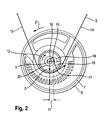
- Fig. 2 shows in detail the forces acting on the drive side. It is the pivot point of a lever whose load arm 16 forms the distance from the central axis 10 to the motor shaft 3. Through the distance from the pivot axis 10 to a point 17 at which the belt 5 acts on the load side on the drive gear 2, the power arm 18 of the lever is formed. Characterized in that the drive-side gear 2 drives the driven side gear via the load strand 14, engages the tangent point 17 of the load strand 14 on the drive-side gear 2, which is dependent on the load of the driven-side gear 6.
- the pivot point of the lever 3, 10, 17 corresponds to this power arm side force a torque (indicated by the arrow 19), the lastarm paragraph on the motor shaft 3 results in a force 20, which can rotate the turntable 7 in the direction of rotation 21.
- the shaft 3 can be pivoted with respect to the central axis 10 in the clamping direction.
- Power arm 18 and load arm 16 are arranged with respect to the central axis 10 so that the rotation causes a pivoting of the shaft 3 in the clamping direction.
- the tension direction is the direction in which the gear 2 must be moved to tension the belt. In the present case, the clamping direction points away from that of the driven-side gear 6.
- the belt tension 20 can automatically adapt to the load of the traction drive. At lower load on the drive, the belt 5 is less tensioned, at higher load it tensions more.
- the turntable 7 is provided with a projection 22 which can abut on projections 23 and 24 which are integrally connected to the housing to the angle at which the turntable 7 in the hollow cylinder 8 rotatable and thus the motor shaft 3 is pivotable, to limit to about 15 °. In this way, a minimum belt tension is set at which the belt 5 still sits tight enough not to flutter, and a maximum belt tension at which the transmission, in particular the belt 5 and the bearings, is not overloaded.
- a coil spring 25 one end of which is fixed to the turntable 7 and the other end to the bottom member 9, the turntable 7 against the direction 21 before.
- the helical spring 25 can return the motor shaft 6 against the clamping direction when the traction mechanism drive 1 is released in order to relieve the belt 5.
- it determines the relationship between the load and the tensioning force 20.
- the output-side gear 6 is also equipped with an internal toothing 26 which in a in the driven-side gear. 6 arranged further gear 27 engages to drive this.
- the further gear 27 can drive another tool, preferably a mixing tool.
- the gear ratio between the driven side gears 6 and 27 is approximately 1 to 5, that is, the further gear 26 rotates at approximately the same speed as the drive side gear 2.
- To couple the tools are both output side gears 26, 27 with coupling devices 28, 29 equipped.
Landscapes
- Engineering & Computer Science (AREA)
- General Engineering & Computer Science (AREA)
- Mechanical Engineering (AREA)
- Food Science & Technology (AREA)
- Devices For Conveying Motion By Means Of Endless Flexible Members (AREA)
- Food-Manufacturing Devices (AREA)
- Friction Gearing (AREA)
- Mechanical Control Devices (AREA)
- Baking, Grill, Roasting (AREA)
- Cookers (AREA)
Priority Applications (2)
| Application Number | Priority Date | Filing Date | Title |
|---|---|---|---|
| PL08701469T PL2117394T3 (pl) | 2007-02-01 | 2008-01-15 | Napęd cięgnowy do urządzenia gospodarstwa domowego |
| SI200830358T SI2117394T1 (sl) | 2007-02-01 | 2008-01-15 | Pogon vlečnega sredstva za gospodinjski aparat |
Applications Claiming Priority (2)
| Application Number | Priority Date | Filing Date | Title |
|---|---|---|---|
| DE102007005108A DE102007005108A1 (de) | 2007-02-01 | 2007-02-01 | Zugmittelantrieb für ein Haushaltsgerät |
| PCT/EP2008/050356 WO2008092731A1 (de) | 2007-02-01 | 2008-01-15 | Zugmittelantrieb für ein haushaltsgerät |
Publications (2)
| Publication Number | Publication Date |
|---|---|
| EP2117394A1 EP2117394A1 (de) | 2009-11-18 |
| EP2117394B1 true EP2117394B1 (de) | 2011-06-01 |
Family
ID=39092049
Family Applications (1)
| Application Number | Title | Priority Date | Filing Date |
|---|---|---|---|
| EP08701469A Not-in-force EP2117394B1 (de) | 2007-02-01 | 2008-01-15 | Zugmittelantrieb für ein haushaltsgerät |
Country Status (6)
| Country | Link |
|---|---|
| EP (1) | EP2117394B1 (pl) |
| AT (1) | ATE511376T1 (pl) |
| DE (1) | DE102007005108A1 (pl) |
| PL (1) | PL2117394T3 (pl) |
| SI (1) | SI2117394T1 (pl) |
| WO (1) | WO2008092731A1 (pl) |
Families Citing this family (2)
| Publication number | Priority date | Publication date | Assignee | Title |
|---|---|---|---|---|
| DE102016204677A1 (de) | 2015-04-01 | 2016-10-06 | BSH Hausgeräte GmbH | Haushaltsgerät mit Wellgetriebe und Verfahren zu seinem Betrieb |
| DE102018216302A1 (de) * | 2018-09-25 | 2020-03-26 | BSH Hausgeräte GmbH | Rolle für einen Zugmitteltrieb |
Family Cites Families (7)
| Publication number | Priority date | Publication date | Assignee | Title |
|---|---|---|---|---|
| CH163084A (de) | 1932-06-14 | 1933-07-31 | Limited Wearn S Inventions | Kraftübertragungsvorrichtung. |
| NO127023B (pl) * | 1966-01-20 | 1973-04-24 | Yorkshire Ind Inc | |
| DE3433004A1 (de) | 1984-09-07 | 1986-03-20 | Bosch-Siemens Hausgeräte GmbH, 7000 Stuttgart | Getriebe fuer ein elektromotorisches haushaltsgeraet |
| EP0498902B1 (de) | 1991-02-11 | 1994-11-30 | LITEF GmbH | Faseroptisches Sagnac-Interferometer mit digitaler Phasenmodulation zur Drehratenmessung |
| DE69312980T2 (de) | 1992-02-18 | 1998-02-12 | Philips Electronics Nv | Küchenmaschine mit verschiebbarem Wellenende |
| EP1548326A2 (en) * | 2000-06-16 | 2005-06-29 | Fabian W. Gibson | Timing belt autotensioner with an anti-tooth skip mechanism |
| US6705581B2 (en) | 2001-05-26 | 2004-03-16 | Pacsci Motion Control, Inc. | Pivotable motor mounting apparatus |
-
2007
- 2007-02-01 DE DE102007005108A patent/DE102007005108A1/de not_active Withdrawn
-
2008
- 2008-01-15 AT AT08701469T patent/ATE511376T1/de active
- 2008-01-15 WO PCT/EP2008/050356 patent/WO2008092731A1/de not_active Ceased
- 2008-01-15 SI SI200830358T patent/SI2117394T1/sl unknown
- 2008-01-15 EP EP08701469A patent/EP2117394B1/de not_active Not-in-force
- 2008-01-15 PL PL08701469T patent/PL2117394T3/pl unknown
Also Published As
| Publication number | Publication date |
|---|---|
| PL2117394T3 (pl) | 2011-10-31 |
| DE102007005108A1 (de) | 2008-08-07 |
| SI2117394T1 (sl) | 2011-10-28 |
| EP2117394A1 (de) | 2009-11-18 |
| WO2008092731A1 (de) | 2008-08-07 |
| ATE511376T1 (de) | 2011-06-15 |
Similar Documents
| Publication | Publication Date | Title |
|---|---|---|
| EP1125070B1 (de) | Spanneinrichtung für ein zugmittel | |
| DE3529816C2 (pl) | ||
| DE3313191C2 (de) | Getriebe für Zusatzeinrichtungen | |
| DE19849886A1 (de) | Riementrieb, insbesondere bei Brennkraftmaschinen zum Antrieb von Nebenaggregaten eines Fahrzeugs | |
| DE60124669T2 (de) | Kupplungsanordnung für rotierendes scheibenförmiges Werkzeug | |
| EP0195853A1 (de) | Kupplung für kraftgetriebene Schraubwerkzeuge | |
| WO2009112024A2 (de) | Vorrichtung zur verstellung des anstellwinkels eines rotorblattes einer windenergieanlage | |
| DE102015105655B3 (de) | Spannvorrichtung für eine Rührwerkskugelmühle mit Riemen- oder Kettenantrieb und Rührwerkskugelmühle | |
| EP3708753A1 (de) | Deckelbeschlag zum schwenkbaren befestigen eines deckels an einen möbelkorpus | |
| WO2001077521A1 (de) | Vorrichtung zum kuppeln mindestens eines nebenaggregats mit einem hauptaggregat | |
| WO1988004219A1 (fr) | Outillage a main portatif, notamment meuleuse d'angle | |
| DE3104201C2 (de) | Riemenspannvorrichtung | |
| EP1558859B1 (de) | Feder- und dämpfungsvorrichtung | |
| WO2008092731A1 (de) | Zugmittelantrieb für ein haushaltsgerät | |
| EP1188703B1 (de) | Vorrichtung zum Steuern eines Spulenrahmens einer Textilmaschine | |
| DE837530C (de) | Elektrosschrauber mit Rutschkupplung und ankuppelbarer Schraubenzieherspindel | |
| EP2352935B1 (de) | Scheibensatzanordnung für ein ketten-cvt mit einer funktionsoptimierten scheibensatzkontur | |
| DE202009009145U1 (de) | Riementrieb | |
| DE2852493C2 (de) | Untersetzungsgetriebe | |
| DE10254125B4 (de) | Elektromotorischer Möbelantrieb zum Verstellen von Teilen eines Möbels relativ zueinander | |
| EP1564443B1 (de) | Ausrückbarer Reibradspanner | |
| DE102004005748A1 (de) | Zugmittelgetriebe mit exzentrischer Einstellung | |
| DE3333853A1 (de) | Dreh- und einstellwerkzeug fuer werkstuecke mit zylindrischer mantelflaeche, insbesondere fuer spurstangen an kraftfahrzeugen | |
| WO2010054928A1 (de) | Halbautomatische spannvorrichtung einer verbrennungskraftmaschine | |
| EP0363600A1 (de) | Vorrichtung zur Winkelverstellung einer Nockenwelle |
Legal Events
| Date | Code | Title | Description |
|---|---|---|---|
| PUAI | Public reference made under article 153(3) epc to a published international application that has entered the european phase |
Free format text: ORIGINAL CODE: 0009012 |
|
| 17P | Request for examination filed |
Effective date: 20090901 |
|
| AK | Designated contracting states |
Kind code of ref document: A1 Designated state(s): AT BE BG CH CY CZ DE DK EE ES FI FR GB GR HR HU IE IS IT LI LT LU LV MC MT NL NO PL PT RO SE SI SK TR |
|
| DAX | Request for extension of the european patent (deleted) | ||
| GRAP | Despatch of communication of intention to grant a patent |
Free format text: ORIGINAL CODE: EPIDOSNIGR1 |
|
| RIN1 | Information on inventor provided before grant (corrected) |
Inventor name: PAVLOVIC, HENRIK Inventor name: MAZEJ, STANISLAV Inventor name: ZIBRET, IGOR |
|
| GRAS | Grant fee paid |
Free format text: ORIGINAL CODE: EPIDOSNIGR3 |
|
| GRAA | (expected) grant |
Free format text: ORIGINAL CODE: 0009210 |
|
| AK | Designated contracting states |
Kind code of ref document: B1 Designated state(s): AT BE BG CH CY CZ DE DK EE ES FI FR GB GR HR HU IE IS IT LI LT LU LV MC MT NL NO PL PT RO SE SI SK TR |
|
| REG | Reference to a national code |
Ref country code: GB Ref legal event code: FG4D Free format text: NOT ENGLISH |
|
| REG | Reference to a national code |
Ref country code: CH Ref legal event code: EP |
|
| REG | Reference to a national code |
Ref country code: IE Ref legal event code: FG4D Free format text: LANGUAGE OF EP DOCUMENT: GERMAN |
|
| REG | Reference to a national code |
Ref country code: DE Ref legal event code: R096 Ref document number: 502008003735 Country of ref document: DE Effective date: 20110714 |
|
| REG | Reference to a national code |
Ref country code: NL Ref legal event code: VDEP Effective date: 20110601 |
|
| PG25 | Lapsed in a contracting state [announced via postgrant information from national office to epo] |
Ref country code: LT Free format text: LAPSE BECAUSE OF FAILURE TO SUBMIT A TRANSLATION OF THE DESCRIPTION OR TO PAY THE FEE WITHIN THE PRESCRIBED TIME-LIMIT Effective date: 20110601 Ref country code: NO Free format text: LAPSE BECAUSE OF FAILURE TO SUBMIT A TRANSLATION OF THE DESCRIPTION OR TO PAY THE FEE WITHIN THE PRESCRIBED TIME-LIMIT Effective date: 20110901 Ref country code: HR Free format text: LAPSE BECAUSE OF FAILURE TO SUBMIT A TRANSLATION OF THE DESCRIPTION OR TO PAY THE FEE WITHIN THE PRESCRIBED TIME-LIMIT Effective date: 20110601 Ref country code: SE Free format text: LAPSE BECAUSE OF FAILURE TO SUBMIT A TRANSLATION OF THE DESCRIPTION OR TO PAY THE FEE WITHIN THE PRESCRIBED TIME-LIMIT Effective date: 20110601 |
|
| REG | Reference to a national code |
Ref country code: PL Ref legal event code: T3 |
|
| REG | Reference to a national code |
Ref country code: HU Ref legal event code: AG4A Ref document number: E011447 Country of ref document: HU |
|
| PG25 | Lapsed in a contracting state [announced via postgrant information from national office to epo] |
Ref country code: FI Free format text: LAPSE BECAUSE OF FAILURE TO SUBMIT A TRANSLATION OF THE DESCRIPTION OR TO PAY THE FEE WITHIN THE PRESCRIBED TIME-LIMIT Effective date: 20110601 Ref country code: LV Free format text: LAPSE BECAUSE OF FAILURE TO SUBMIT A TRANSLATION OF THE DESCRIPTION OR TO PAY THE FEE WITHIN THE PRESCRIBED TIME-LIMIT Effective date: 20110601 Ref country code: GR Free format text: LAPSE BECAUSE OF FAILURE TO SUBMIT A TRANSLATION OF THE DESCRIPTION OR TO PAY THE FEE WITHIN THE PRESCRIBED TIME-LIMIT Effective date: 20110902 Ref country code: ES Free format text: LAPSE BECAUSE OF FAILURE TO SUBMIT A TRANSLATION OF THE DESCRIPTION OR TO PAY THE FEE WITHIN THE PRESCRIBED TIME-LIMIT Effective date: 20110912 Ref country code: CY Free format text: LAPSE BECAUSE OF FAILURE TO SUBMIT A TRANSLATION OF THE DESCRIPTION OR TO PAY THE FEE WITHIN THE PRESCRIBED TIME-LIMIT Effective date: 20110601 |
|
| REG | Reference to a national code |
Ref country code: IE Ref legal event code: FD4D |
|
| PG25 | Lapsed in a contracting state [announced via postgrant information from national office to epo] |
Ref country code: NL Free format text: LAPSE BECAUSE OF FAILURE TO SUBMIT A TRANSLATION OF THE DESCRIPTION OR TO PAY THE FEE WITHIN THE PRESCRIBED TIME-LIMIT Effective date: 20110601 |
|
| PG25 | Lapsed in a contracting state [announced via postgrant information from national office to epo] |
Ref country code: CZ Free format text: LAPSE BECAUSE OF FAILURE TO SUBMIT A TRANSLATION OF THE DESCRIPTION OR TO PAY THE FEE WITHIN THE PRESCRIBED TIME-LIMIT Effective date: 20110601 Ref country code: IE Free format text: LAPSE BECAUSE OF FAILURE TO SUBMIT A TRANSLATION OF THE DESCRIPTION OR TO PAY THE FEE WITHIN THE PRESCRIBED TIME-LIMIT Effective date: 20110601 Ref country code: IS Free format text: LAPSE BECAUSE OF FAILURE TO SUBMIT A TRANSLATION OF THE DESCRIPTION OR TO PAY THE FEE WITHIN THE PRESCRIBED TIME-LIMIT Effective date: 20111001 Ref country code: PT Free format text: LAPSE BECAUSE OF FAILURE TO SUBMIT A TRANSLATION OF THE DESCRIPTION OR TO PAY THE FEE WITHIN THE PRESCRIBED TIME-LIMIT Effective date: 20111003 Ref country code: EE Free format text: LAPSE BECAUSE OF FAILURE TO SUBMIT A TRANSLATION OF THE DESCRIPTION OR TO PAY THE FEE WITHIN THE PRESCRIBED TIME-LIMIT Effective date: 20110601 |
|
| PG25 | Lapsed in a contracting state [announced via postgrant information from national office to epo] |
Ref country code: SK Free format text: LAPSE BECAUSE OF FAILURE TO SUBMIT A TRANSLATION OF THE DESCRIPTION OR TO PAY THE FEE WITHIN THE PRESCRIBED TIME-LIMIT Effective date: 20110601 Ref country code: RO Free format text: LAPSE BECAUSE OF FAILURE TO SUBMIT A TRANSLATION OF THE DESCRIPTION OR TO PAY THE FEE WITHIN THE PRESCRIBED TIME-LIMIT Effective date: 20110601 |
|
| PLBE | No opposition filed within time limit |
Free format text: ORIGINAL CODE: 0009261 |
|
| STAA | Information on the status of an ep patent application or granted ep patent |
Free format text: STATUS: NO OPPOSITION FILED WITHIN TIME LIMIT |
|
| 26N | No opposition filed |
Effective date: 20120302 |
|
| REG | Reference to a national code |
Ref country code: DE Ref legal event code: R097 Ref document number: 502008003735 Country of ref document: DE Effective date: 20120302 |
|
| PG25 | Lapsed in a contracting state [announced via postgrant information from national office to epo] |
Ref country code: DK Free format text: LAPSE BECAUSE OF FAILURE TO SUBMIT A TRANSLATION OF THE DESCRIPTION OR TO PAY THE FEE WITHIN THE PRESCRIBED TIME-LIMIT Effective date: 20110601 |
|
| BERE | Be: lapsed |
Owner name: BSH BOSCH UND SIEMENS HAUSGERATE G.M.B.H. Effective date: 20120131 |
|
| PG25 | Lapsed in a contracting state [announced via postgrant information from national office to epo] |
Ref country code: MC Free format text: LAPSE BECAUSE OF NON-PAYMENT OF DUE FEES Effective date: 20120131 |
|
| REG | Reference to a national code |
Ref country code: CH Ref legal event code: PL |
|
| PG25 | Lapsed in a contracting state [announced via postgrant information from national office to epo] |
Ref country code: CH Free format text: LAPSE BECAUSE OF NON-PAYMENT OF DUE FEES Effective date: 20120131 Ref country code: LI Free format text: LAPSE BECAUSE OF NON-PAYMENT OF DUE FEES Effective date: 20120131 |
|
| PG25 | Lapsed in a contracting state [announced via postgrant information from national office to epo] |
Ref country code: BE Free format text: LAPSE BECAUSE OF NON-PAYMENT OF DUE FEES Effective date: 20120131 |
|
| PG25 | Lapsed in a contracting state [announced via postgrant information from national office to epo] |
Ref country code: BG Free format text: LAPSE BECAUSE OF FAILURE TO SUBMIT A TRANSLATION OF THE DESCRIPTION OR TO PAY THE FEE WITHIN THE PRESCRIBED TIME-LIMIT Effective date: 20110901 |
|
| PG25 | Lapsed in a contracting state [announced via postgrant information from national office to epo] |
Ref country code: MT Free format text: LAPSE BECAUSE OF FAILURE TO SUBMIT A TRANSLATION OF THE DESCRIPTION OR TO PAY THE FEE WITHIN THE PRESCRIBED TIME-LIMIT Effective date: 20110601 |
|
| PG25 | Lapsed in a contracting state [announced via postgrant information from national office to epo] |
Ref country code: TR Free format text: LAPSE BECAUSE OF FAILURE TO SUBMIT A TRANSLATION OF THE DESCRIPTION OR TO PAY THE FEE WITHIN THE PRESCRIBED TIME-LIMIT Effective date: 20110601 |
|
| PG25 | Lapsed in a contracting state [announced via postgrant information from national office to epo] |
Ref country code: LU Free format text: LAPSE BECAUSE OF NON-PAYMENT OF DUE FEES Effective date: 20120115 |
|
| REG | Reference to a national code |
Ref country code: FR Ref legal event code: PLFP Year of fee payment: 8 |
|
| REG | Reference to a national code |
Ref country code: DE Ref legal event code: R081 Ref document number: 502008003735 Country of ref document: DE Owner name: BSH HAUSGERAETE GMBH, DE Free format text: FORMER OWNER: BSH BOSCH UND SIEMENS HAUSGERAETE GMBH, 81739 MUENCHEN, DE Effective date: 20150408 |
|
| REG | Reference to a national code |
Ref country code: SI Ref legal event code: SP73 Owner name: BSH HAUSGERAETE GMBH; DE Effective date: 20150529 |
|
| REG | Reference to a national code |
Ref country code: AT Ref legal event code: HC Ref document number: 511376 Country of ref document: AT Kind code of ref document: T Owner name: BSH HAUSGERAETE GMBH, DE Effective date: 20150528 |
|
| REG | Reference to a national code |
Ref country code: HU Ref legal event code: HC9C Owner name: BSH HAUSGERAETE GMBH, DE Free format text: FORMER OWNER(S): BSH BOSCH UND SIEMENS HAUSGERAETE GMBH, DE |
|
| REG | Reference to a national code |
Ref country code: FR Ref legal event code: CD Owner name: BSH HAUSGERATE GMBH, DE Effective date: 20151022 |
|
| REG | Reference to a national code |
Ref country code: FR Ref legal event code: PLFP Year of fee payment: 9 |
|
| REG | Reference to a national code |
Ref country code: FR Ref legal event code: PLFP Year of fee payment: 10 |
|
| REG | Reference to a national code |
Ref country code: FR Ref legal event code: PLFP Year of fee payment: 11 |
|
| PGFP | Annual fee paid to national office [announced via postgrant information from national office to epo] |
Ref country code: FR Payment date: 20230123 Year of fee payment: 16 Ref country code: AT Payment date: 20230118 Year of fee payment: 16 |
|
| PGFP | Annual fee paid to national office [announced via postgrant information from national office to epo] |
Ref country code: SI Payment date: 20230104 Year of fee payment: 16 Ref country code: PL Payment date: 20230103 Year of fee payment: 16 Ref country code: IT Payment date: 20230131 Year of fee payment: 16 Ref country code: HU Payment date: 20230120 Year of fee payment: 16 Ref country code: GB Payment date: 20230124 Year of fee payment: 16 Ref country code: DE Payment date: 20230131 Year of fee payment: 16 |
|
| REG | Reference to a national code |
Ref country code: DE Ref legal event code: R119 Ref document number: 502008003735 Country of ref document: DE |
|
| REG | Reference to a national code |
Ref country code: AT Ref legal event code: MM01 Ref document number: 511376 Country of ref document: AT Kind code of ref document: T Effective date: 20240115 |
|
| GBPC | Gb: european patent ceased through non-payment of renewal fee |
Effective date: 20240115 |
|
| PG25 | Lapsed in a contracting state [announced via postgrant information from national office to epo] |
Ref country code: DE Free format text: LAPSE BECAUSE OF NON-PAYMENT OF DUE FEES Effective date: 20240801 |
|
| PG25 | Lapsed in a contracting state [announced via postgrant information from national office to epo] |
Ref country code: GB Free format text: LAPSE BECAUSE OF NON-PAYMENT OF DUE FEES Effective date: 20240115 |
|
| PG25 | Lapsed in a contracting state [announced via postgrant information from national office to epo] |
Ref country code: FR Free format text: LAPSE BECAUSE OF NON-PAYMENT OF DUE FEES Effective date: 20240131 |
|
| PG25 | Lapsed in a contracting state [announced via postgrant information from national office to epo] |
Ref country code: AT Free format text: LAPSE BECAUSE OF NON-PAYMENT OF DUE FEES Effective date: 20240115 |
|
| PG25 | Lapsed in a contracting state [announced via postgrant information from national office to epo] |
Ref country code: SI Free format text: LAPSE BECAUSE OF NON-PAYMENT OF DUE FEES Effective date: 20240116 Ref country code: HU Free format text: LAPSE BECAUSE OF NON-PAYMENT OF DUE FEES Effective date: 20240116 |
|
| PG25 | Lapsed in a contracting state [announced via postgrant information from national office to epo] |
Ref country code: SI Free format text: LAPSE BECAUSE OF NON-PAYMENT OF DUE FEES Effective date: 20240116 Ref country code: HU Free format text: LAPSE BECAUSE OF NON-PAYMENT OF DUE FEES Effective date: 20240116 Ref country code: GB Free format text: LAPSE BECAUSE OF NON-PAYMENT OF DUE FEES Effective date: 20240115 Ref country code: FR Free format text: LAPSE BECAUSE OF NON-PAYMENT OF DUE FEES Effective date: 20240131 Ref country code: DE Free format text: LAPSE BECAUSE OF NON-PAYMENT OF DUE FEES Effective date: 20240801 Ref country code: AT Free format text: LAPSE BECAUSE OF NON-PAYMENT OF DUE FEES Effective date: 20240115 |
|
| REG | Reference to a national code |
Ref country code: SI Ref legal event code: KO00 Effective date: 20240930 |
|
| PG25 | Lapsed in a contracting state [announced via postgrant information from national office to epo] |
Ref country code: IT Free format text: LAPSE BECAUSE OF NON-PAYMENT OF DUE FEES Effective date: 20240115 |
|
| PG25 | Lapsed in a contracting state [announced via postgrant information from national office to epo] |
Ref country code: PL Free format text: LAPSE BECAUSE OF NON-PAYMENT OF DUE FEES Effective date: 20240115 |