EP2116740A2 - Feder-Dämpfungssystem - Google Patents
Feder-Dämpfungssystem Download PDFInfo
- Publication number
- EP2116740A2 EP2116740A2 EP09005453A EP09005453A EP2116740A2 EP 2116740 A2 EP2116740 A2 EP 2116740A2 EP 09005453 A EP09005453 A EP 09005453A EP 09005453 A EP09005453 A EP 09005453A EP 2116740 A2 EP2116740 A2 EP 2116740A2
- Authority
- EP
- European Patent Office
- Prior art keywords
- spring
- damping
- shaft
- damping system
- end caps
- Prior art date
- Legal status (The legal status is an assumption and is not a legal conclusion. Google has not performed a legal analysis and makes no representation as to the accuracy of the status listed.)
- Granted
Links
- 238000013016 damping Methods 0.000 title claims abstract description 49
- 239000000835 fiber Substances 0.000 claims description 3
- 239000002184 metal Substances 0.000 claims description 3
- 230000006978 adaptation Effects 0.000 claims 1
- 230000006835 compression Effects 0.000 description 1
- 238000007906 compression Methods 0.000 description 1
- 230000000284 resting effect Effects 0.000 description 1
- 125000006850 spacer group Chemical group 0.000 description 1
- 230000001629 suppression Effects 0.000 description 1
- 239000000725 suspension Substances 0.000 description 1
Images
Classifications
-
- F—MECHANICAL ENGINEERING; LIGHTING; HEATING; WEAPONS; BLASTING
- F16—ENGINEERING ELEMENTS AND UNITS; GENERAL MEASURES FOR PRODUCING AND MAINTAINING EFFECTIVE FUNCTIONING OF MACHINES OR INSTALLATIONS; THERMAL INSULATION IN GENERAL
- F16F—SPRINGS; SHOCK-ABSORBERS; MEANS FOR DAMPING VIBRATION
- F16F15/00—Suppression of vibrations in systems; Means or arrangements for avoiding or reducing out-of-balance forces, e.g. due to motion
- F16F15/02—Suppression of vibrations of non-rotating, e.g. reciprocating systems; Suppression of vibrations of rotating systems by use of members not moving with the rotating systems
- F16F15/04—Suppression of vibrations of non-rotating, e.g. reciprocating systems; Suppression of vibrations of rotating systems by use of members not moving with the rotating systems using elastic means
- F16F15/046—Suppression of vibrations of non-rotating, e.g. reciprocating systems; Suppression of vibrations of rotating systems by use of members not moving with the rotating systems using elastic means using combinations of springs of different kinds
-
- B—PERFORMING OPERATIONS; TRANSPORTING
- B64—AIRCRAFT; AVIATION; COSMONAUTICS
- B64G—COSMONAUTICS; VEHICLES OR EQUIPMENT THEREFOR
- B64G1/00—Cosmonautic vehicles
- B64G1/22—Parts of, or equipment specially adapted for fitting in or to, cosmonautic vehicles
- B64G1/64—Systems for coupling or separating cosmonautic vehicles or parts thereof, e.g. docking arrangements
- B64G1/641—Interstage or payload connectors
- B64G1/6425—Interstage or payload connectors arrangements for damping vibrations
-
- B—PERFORMING OPERATIONS; TRANSPORTING
- B64—AIRCRAFT; AVIATION; COSMONAUTICS
- B64G—COSMONAUTICS; VEHICLES OR EQUIPMENT THEREFOR
- B64G1/00—Cosmonautic vehicles
- B64G1/14—Space shuttles
-
- F—MECHANICAL ENGINEERING; LIGHTING; HEATING; WEAPONS; BLASTING
- F16—ENGINEERING ELEMENTS AND UNITS; GENERAL MEASURES FOR PRODUCING AND MAINTAINING EFFECTIVE FUNCTIONING OF MACHINES OR INSTALLATIONS; THERMAL INSULATION IN GENERAL
- F16F—SPRINGS; SHOCK-ABSORBERS; MEANS FOR DAMPING VIBRATION
- F16F2228/00—Functional characteristics, e.g. variability, frequency-dependence
- F16F2228/08—Functional characteristics, e.g. variability, frequency-dependence pre-stressed
Definitions
- the invention consists of a spring-damping system in 3-axes for load platforms as a support structure in spacecraft for receiving payloads on pallets, wherein a plurality of spring-damping elements are assigned.
- payloads are partially received via fixtures that allow removal of the unit from a space shuttle using a robot.
- payloads usually mounted on a plate are screwed onto load platforms in the space shuttle.
- a recording of the load platform as a support structure is carried out in a known manner with interposition of a spring-damping system, as it is known from DE 10 2006 054 274 B3 is known. This allows suppression of roll movements in two axes and independent adjustment of suspension and damping in all three axes.
- the object of the invention is to create a pallet with payloads on a load platform as a support structure by spring elements to avoid medium to high-frequency stresses in a simple manner, which ensure deployment in aerospace.
- each spring-damping element is formed by outgoing from the support structure bolt with a shaft which is guided through a receiving opening of the pallet and on the shank of the bolt respectively between a pot receptacle and an end cap at least two spring-damping cushions are arranged one behind the other, which are arranged on both sides of an abutment in the receiving opening and held by an outboard adjustment, such as a nut on the shaft with an adjustable bias.
- spring-damping pads are formed of a metal mesh with fibers of strands.
- the end caps associated with the abutment as a web have receptacles, wherein the end caps have a passage opening to form a distance from the shaft.
- plate springs abut with disk elements on the spring-damping cushion as intermediate layers.
- the height of the formed edge zones of the pot receivers and / or end caps are dimensioned to match a required radial rigidity of the spring-damping pads.
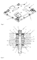
- a pallet 1 for payloads on a load platform 2 via intermediate spring damping elements 3 is arranged.
- Each spring damping element 3 is formed by a bolt 4, via which the force from the vibration exciter by a shaft 5 and via a respective pot receiving 6.7 forwarded to successive spring damping pads 8 and 9.
- each end caps 10, 11 are interposed, which pass on the force via a web 12 as an abutment against the element to be damped pallet 1.
- the spring-damping pads 8, 9 are biased by washers 15, 16.
- the size of the bias is set via a nut 17.
- the nut 17 is fixed after adjustment in position by locking with the aid of a screw 18.
- the spring-damping pads 8, 9 are formed of a metal mesh with fibers of strands. Since these spring-damping pads usually have a non-linear-progressive characteristic, in the axial direction, the spring constant and thus the natural frequency of the system can be changed via bias of the spring-damping cushion. For this purpose, the mother 17 is adjusted accordingly.
- the disc springs 13, 14 ensure that even then no gap between one of the spring cushions 8, 9 and the corresponding end cap 10, 11 is formed when, after discharge of one of the spring-damping cushion 8, 9, due to the internal friction, no longer returns exactly to its resting state, but remains a few tenths of a mm in front of it.
- the force is introduced into the spring-cushioning cushion 8, 9 via the shaft 5 and the pot receivers 6, 7. The force is then on the end caps 10, 11 of the spring-damping pads 7 and 8 in the pallet 1 forwarded via the web 12. Also in the radial direction forces are largely passed through compression by spring-damping cushion and only a small part of thrust. This is advantageous because the carrying capacity of the spring-damping pads 8, 9 is lower under shear load than under compressive load.
- the stiffness can be influenced by the height of the pressure-transmitting elements in the radial direction.
- the size of the bias voltage can, as stated, adjust the nut 17.
- a recess on the shaft 5 is provided, against which the nut 17 is screwed and then secured by a sufficient bias against a solution under vibration.
- a correct distance between the spring-damping pads 8, 9, and thus the bias, must be adjusted via spacers on the recess.
- the distance can also be adjusted only via the nut 17 and the rotation under vibration loads is prevented by a lock screw 18.
- This screw 18 is provided with a left-hand thread, so that a common rotation of the nut 17 and screw 18 is geometrically prevented.
- the nut 17 and the screw 18 is secured by means of self-locking threaded inserts against rotation.
Landscapes
- Engineering & Computer Science (AREA)
- Mechanical Engineering (AREA)
- Aviation & Aerospace Engineering (AREA)
- General Engineering & Computer Science (AREA)
- Remote Sensing (AREA)
- Physics & Mathematics (AREA)
- Acoustics & Sound (AREA)
- Vibration Prevention Devices (AREA)
- Springs (AREA)
- Vibration Dampers (AREA)
Abstract
Description
- Die Erfindung besteht aus einem Feder-Dämpfungssystem in 3-Achsen für Lastplattformen als Haltestruktur in Raumfahrzeugen zur Aufnahme von Nutzlasten über Paletten, wobei mehrere Feder-Dämpfungselemente zugeordnet sind.
- Zum Transport zu einer Raumstation werden Nutzlasten zum Teil über Haltevorrichtungen aufgenommen, die eine Entnahme der Einheit aus einem Space Shuttle mit Hilfe eines Roboters ermöglicht. Hierbei sind üblicherweise auf einer Platte montierte Nutzlasten auf Lastplattformen im Space Shuttle aufgeschraubt. Eine Aufnahme der Lastplattform als Haltestruktur erfolgt in bekannter Weise unter zwischenschaltung eines Feder-Dämpfungssystems, wie es aus der
DE 10 2006 054 274 B3 bekannt ist. Dabei wird eine Unterdrückung von Wankbewegungen in zwei Achsen und eine unabhängige Anpassung von Federung und Dämpfung in allen drei Achsen ermöglicht. - Dieser Aufwand ist für eine Durchführung der Dämpfung sehr niedriger Frequenzen der aufgenommenen Nutzlasten relativ aufwendig, da mit der bekannten Ausbildung zusätzlich weitere Forderungen erfüllt werden.
- Die Aufgabe der Erfindung ist es, eine Palette mit Nutzlasten auf eine Lastplattform als Haltestruktur durch Federelemente zur Vermeidung von mittel- bis hochfrequenten Beanspruchungen auf einfache Weise zu schaffen, die einen Einsatz in der Raumfahrt gewährleisten.
- Die Lösung dieser Aufgabe erfolgt erfindungsgemäß dadurch, daß die Palette mit Nutzlasten über Feder-Dämpfungselemente angeordnet und jedes Feder-Dämpfungselement durch von der Haltestruktur ausgehende Bolzen mit einem Schaft gebildet ist, der durch eine Aufnahmeöffnung der Palette geführt ist und auf den Schaft des Bolzens jeweils zwischen einer Topfaufnahme und einer Endkappe mindestens zwei hintereinander liegende Feder-Dämpfungs-Kissen angeordnet sind, die beiderseits eines Gegenlagers in der Aufnahmeöffnung angeordnet sowie über ein außenliegendes Einstellelement, wie eine Mutter, am Schaft mit einer einstellbaren Vorspannung gehalten sind.
- Hierdurch ist es möglich, durch eine einfache Anordnung von der Lastplattform als Haltestruktur übertragenden niederfrequenten Beanspruchungen in drei Achsen herabzusetzen.
- Eine einfache Ausbildung besteht darin, daß die Feder-Dämpfungs-Kissen aus einem Metallgeflecht mit Fasern aus Litzen gebildet sind.
- Zur verbesserten Lagerung und Einstellung wird vorgeschlagen, daß die dem Gegenlager als Steg zugeordneten Endkappen Aufnahmen aufweisen, wobei die Endkappen eine Durchtrittsöffnung unter Bildung eines Abstandes zum Schaft besitzen.
- Zur Verbesserung der Linearisierung des Feder-Dämpfungs-Kissen ist vorgesehen, daß Tellerfedern mit Scheibenelementen am Feder-Dämpfungs-Kissen als Zwischenlagen anliegen.
- Ferner wird vorgeschlagen, daß die Höhe der gebildeten Randzonen der Topfaufnahmen und/oder Endkappen in Anpassung einer geforderten radialen Steifigkeit der Feder-Dämpfungs-Kissen bemessen sind.
- In der Zeichnung ist ein Ausführungsbeispiel der Erfindung schematisch dargestellt. Es zeigen:
- Fig. 1
- eine Draufsicht auf eine Lastplattform als Haltestruktur mit mehreren eingesetzten Feder-Dämpfungselementen und
- Fig. 2
- eine Schnittdarstellung durch ein Federdämpfungselement zwischen einer Lastplattform und einer aufgesetzten Palette für Nutzlasten.
- Bei der Ausführung eines niederfrequenten Feder-Dämpfungssystems in einem Space Shuttle ist eine Palette 1 für Nutzlasten auf einer Lastplattform 2 über zwischengeschaltete Federdämpfungselemente 3 angeordnet.
- Jedes Federdämpfungselement 3 wird durch einen Bolzen 4 gebildet, über den die Kraft vom Schwingungs-Erreger durch einen Schaft 5 und jeweils über eine Topfaufnahme 6,7 an hintereinander liegende Feder-Dämpfungs-Kissen 8 und 9 weitergeleitet. Hierbei sind jeweils Endkappen 10, 11 zwischengeschaltet, die die Kraft über einen Steg 12 als Gegenlager an das zu dämpfende Element der Palette 1 weitergeben. Mit Hilfe von Tellerfedern 13, 14 werden die Feder-Dämpfungs-Kissen 8, 9 über Unterlegscheiben 15, 16 vorgespannt. Die Größe der Vorspannung wird dabei über eine Mutter 17 eingestellt. Die Mutter 17 wird nach der Einstellung in ihrer Lage durch kontern mit Hilfe einer Schraube 18 fixiert.
- Im Betrieb werden radiale Kräfte über beide Feder-Dämpfungs-Kissen 8, 9 weitergeleitet. Axiale Kräfte werden - entsprechend dem Vorzeichen - über eines der Feder-Dämpfungs-Kissen 8, 9 weitergeleitet. In vielen Fällen ist eine Vorspannung der Feder-Dämpfungs-Kissen 8, 9 erwünscht, um bei Belastung in axialer Richtung einen Spalt zwischen einem der Feder-Dämpfungs-Kissen 8, 9 und der korrespondierenden Endkappen 10, 11 zu vermeiden.
- Die Feder-Dämpfungs-Kissen 8, 9 sind aus einem Metallgeflecht mit Fasern aus Litzen gebildet. Da diese Feder-Dämpfungs-Kissen normalerweise eine nichtlineare -progressive Kennlinie haben, kann in axialer Richtung auch die Federkonstante und damit die Eigenfrequenz des Systems über Vorspannung der Feder-Dämpfungs-Kissen verändert werden. Hierzu wird entsprechend die Mutter 17 eingestellt. Die Tellerfedern 13, 14 sorgen dafür, daß auch dann kein Spalt zwischen einem der Federkissen 8, 9 und der korrespondierenden Endkappe 10, 11 entsteht, wenn nach Entlastung eines der Feder-Dämpfungs-Kissen 8, 9, bedingt durch die innere Reibung, nicht mehr exakt in seinen Ruhezustand zurückkehrt, sondern einige zehntel mm davor verbleibt. Des weiteren kann mit Hilfe der nichtlinearen - degressiven - Charakteristik der Tellerfedern 13, 14 eine teilweise Linearisierung des Gesamtsystems erreicht werden. Die anti-symmetrische Belastung der zwei Feder-Dämpfungs-Kissen 8, 9 in axialer Richtung bewirkt bereits eine teilweise Linearisierung. Von den nichtlinearen Termen in der Federkennlinie heben sich die geraden Terme beider Feder-Dämpfungs-Kissen auf und es verbleiben nur noch ungerade Terme.
- In radialer Richtung erfolgt die Kraft-Einleitung in die Feder-Dämpfungs-Kissen 8, 9 über den Schaft 5 und die Topfaufnahmen 6, 7. Die Kraft wird dann über die Endkappen 10, 11 von den Feder-Dämpfungs-Kissen 7 und 8 in die Palette 1 über den Steg 12 weitergeleitet. Auch in radialer Richtung werden Kräfte zum großen Teil über Kompression durch Feder-Dämpfungs-Kissen weitergeleitet und nur zu einem geringen Teil über Schub. Dieses ist vorteilhaft, da die Tragfähigkeit der Feder-Dämpfungs-Kissen 8, 9 bei Schubbelastung geringer ist als bei Druckbelastung. Die Steifigkeit läßt sich über die Höhe der druckübertragenden Elemente in radialer Richtung beeinflussen. Die Größe der Vorspannung läßt sich, wie ausgeführt, über die Mutter 17 einstellen. Für die Sicherung dieser Einstellung gegenüber Vibrationen ist ein Rezeß am Schaft 5 vorgesehen, gegen den die Mutter 17 geschraubt wird und dann über eine hinreichende Vorspannung gegen eine Lösung unter Vibration gesichert wird. Ein korrekter Abstand zwischen den Feder-Dämpfungs-Kissen 8, 9, und damit die Vorspannung, muß über Distanzringe am Rezeß eingestellt werden.
- Es kann selbstverständlich der Abstand auch nur über die Mutter 17 eingestellt werden und das Verdrehen unter Vibrationslasten wird dabei durch eine Konterschraube 18 verhindert. Diese Schraube 18 ist mit einem Links-Gewinde versehen, so daß ein gemeinsames Verdrehen von Mutter 17 und Schraube 18 geometrisch verhindert wird. Zusätzlich ist vorgesehen, daß die Mutter 17 und die Schraube 18 mit Hilfe selbstsichernder Gewindeeinsätze gegen Verdrehen gesichert wird.
Claims (5)
- Feder-Dämpfungssystem in 3-Achsen für Lastplattformen als Haltestruktur in Raumfahrzeugen zur Aufnahme von Nutzlasten über Paletten, wobei mehrere Feder-Dämpfungselemente zugeordnet sind, dadurch gekennzeichnet, daß die Palette (1) mit Nutzlasten über Feder-Dämpfungselemente (3) angeordnet und jedes Feder-Dämpfungselement durch von der Haltestruktur (2) ausgehende Bolzen (4) mit einem Schaft (5) gebildet ist, der durch eine Aufnahmeöffnung der Palette (1) geführt ist und auf den Schaft (5) des Bolzens (4) jeweils zwischen einer Topfaufnahme (6, 7) und einer Endkappe (10, 11) mindestens zwei hintereinander liegende Feder-Dämpfungs-Kissen (8, 9) angeordnet sind, die beiderseits eines Gegenlagers (12) in der Aufnahmeöffnung angeordnet sowie über ein außenliegendes Einstellelement (17), wie eine Mutter, am Schaft (5) mit einer einstellbaren Vorspannung gehalten sind.
- Feder-Dämpfungssystem nach Anspruch 1, dadurch gekennzeichnet, daß die Feder-Dämpfungs-Kissen (8, 9) aus einem Metallgeflecht mit Fasern aus Litzen gebildet sind.
- Feder-Dämpfungssystem nach Anspruch 1 oder 2,
dadurch gekennzeichnet, daß die dem Gegenlager (12) als Steg zugeordneten Endkappen (10, 11) Aufnahmen aufweisen, wobei die Endkappen (10, 11) eine Durchtrittsöffnung (19) unter Bildung eines Abstandes zum Schaft (5) besitzen. - Feder-Dämpfungssystem nach einem der Ansprüche 1 bis 3, dadurch gekennzeichnet, daß Tellerfedern (9, 10) mit Scheibenelementen (15, 16) am Feder-Dämpfungs-Kissen (8, 9) als zwischenlagen anliegen.
- Feder-Dämpfungssystem nach einem der Ansprüche 1 bis 4, dadurch gekennzeichnet, daß die Höhe der gebildeten Randzonen der Topfaufnahmen (6, 7) und/oder Endkappen (10, 11) in Anpassung einer geforderten radialen Steifigkeit der Feder-Dämpfungs-Kissen (8, 9) bemessen sind.
Applications Claiming Priority (1)
| Application Number | Priority Date | Filing Date | Title |
|---|---|---|---|
| DE102008022467A DE102008022467A1 (de) | 2008-05-07 | 2008-05-07 | Feder-Dämpfungssystem |
Publications (3)
| Publication Number | Publication Date |
|---|---|
| EP2116740A2 true EP2116740A2 (de) | 2009-11-11 |
| EP2116740A3 EP2116740A3 (de) | 2011-11-30 |
| EP2116740B1 EP2116740B1 (de) | 2014-04-30 |
Family
ID=40872264
Family Applications (1)
| Application Number | Title | Priority Date | Filing Date |
|---|---|---|---|
| EP09005453.7A Not-in-force EP2116740B1 (de) | 2008-05-07 | 2009-04-17 | Feder-Dämpfungssystem |
Country Status (4)
| Country | Link |
|---|---|
| US (1) | US8302748B2 (de) |
| EP (1) | EP2116740B1 (de) |
| DE (1) | DE102008022467A1 (de) |
| ES (1) | ES2478244T3 (de) |
Cited By (2)
| Publication number | Priority date | Publication date | Assignee | Title |
|---|---|---|---|---|
| CN106895229A (zh) * | 2015-12-18 | 2017-06-27 | 中国核动力研究设计院 | 一种具备三向限位功能的紧凑式隔振限位结构 |
| CN110566630A (zh) * | 2019-07-26 | 2019-12-13 | 北京空间飞行器总体设计部 | 一种发射段减振和在轨段隔振一体化的载荷支撑装置 |
Families Citing this family (21)
| Publication number | Priority date | Publication date | Assignee | Title |
|---|---|---|---|---|
| FR2942205B1 (fr) * | 2009-02-18 | 2012-08-03 | Airbus France | Attache moteur a courbe charge/deformation adaptee |
| EP3527842A1 (de) * | 2010-12-29 | 2019-08-21 | Newport Corporation | Abstimmbare schwingungsdämpfer und verfahren zu ihrer herstellung und abstimmung |
| US20130154170A1 (en) * | 2011-12-20 | 2013-06-20 | Honeywell International Inc. | Passive isolation devices providing low frequency damping of low mass payloads and spacecraft isolation systems employing the same |
| US9556851B2 (en) | 2013-04-03 | 2017-01-31 | General Electric Company | System for reducing vibration in a wind turbine |
| CN103410911B (zh) * | 2013-08-05 | 2016-03-30 | 上海宇航系统工程研究所 | 一种适应空间环境应用的有效载荷减振装置 |
| US10801574B2 (en) * | 2015-04-29 | 2020-10-13 | The Boeing Company | Dynamic shape maintenance of aerospace subsystems using tuned mass dampers |
| CN106864775A (zh) * | 2015-12-11 | 2017-06-20 | 天津航天瑞莱科技有限公司 | 一种航天器有效载荷减冲击装置 |
| CN106240333B (zh) * | 2016-08-31 | 2018-01-02 | 河南恒发橡塑制品有限公司 | 一种汽车发动机底座减震固定装置 |
| JP6824715B2 (ja) * | 2016-12-07 | 2021-02-03 | Toyo Tire株式会社 | ダイナミックダンパ |
| CN107792403B (zh) * | 2017-09-07 | 2020-01-03 | 湖北航天技术研究院总体设计所 | 一种卫星分离装置 |
| CN107939905B (zh) * | 2017-11-20 | 2019-10-22 | 航天东方红卫星有限公司 | 一种用于微纳卫星减振的星箭适配装置 |
| CN108116697B (zh) * | 2017-12-08 | 2021-06-15 | 浙江大学 | 一种球形卫星分离解锁装置 |
| CN110143296B (zh) * | 2019-04-11 | 2020-11-24 | 上海卫星工程研究所 | 适用于航天器上导热量需求较小单机的减冲支架结构 |
| DE102019125701B4 (de) * | 2019-09-24 | 2023-01-26 | Vibracoustic Se | Dämpfungsvorrichtung sowie Verfahren zu dessen Montage |
| US11313433B2 (en) | 2020-01-15 | 2022-04-26 | Raytheon Company | Shock isolator assembly for a vehicle mounted payload |
| DE102020210256B3 (de) * | 2020-08-12 | 2021-09-23 | Fraunhofer-Gesellschaft zur Förderung der angewandten Forschung eingetragener Verein | Einstellbarer Schwingungstilger, basierend auf Materialkissen |
| CN112032245A (zh) * | 2020-09-11 | 2020-12-04 | 上海航天控制技术研究所 | 一种用于星载加速度计组合的减振系统 |
| EP4229314A1 (de) * | 2020-10-14 | 2023-08-23 | ContiTech Vibration Control GmbH | Montagedesign mit integrierten abstimmbaren haltemerkmalen |
| DE102021203028A1 (de) | 2021-03-26 | 2022-09-29 | Eichler Geschäftsführung GmbH | Schwingungsdämpfer und Schwingungsdämpfungssystem |
| CN113464597B (zh) * | 2021-08-02 | 2022-09-16 | 常州大学 | 一种刚度与阻尼解耦的变阻尼力金属隔振器 |
| FR3130003B1 (fr) * | 2021-12-06 | 2023-12-08 | Thales Sa | Dispositif d'absorption de vibrations, notamment pour un organe de véhicule aérien |
Citations (1)
| Publication number | Priority date | Publication date | Assignee | Title |
|---|---|---|---|---|
| DE102006054274B3 (de) | 2006-11-17 | 2007-12-27 | Astrium Gmbh | 3-Achsen Feder-Dämpfungssystem |
Family Cites Families (19)
| Publication number | Priority date | Publication date | Assignee | Title |
|---|---|---|---|---|
| US2689105A (en) * | 1950-07-08 | 1954-09-14 | Gen Electric | Resilient mount |
| GB715796A (en) * | 1952-05-28 | 1954-09-22 | Robinson Aviat Inc | Improvements in or relating to vibration isolation units |
| US3107905A (en) * | 1960-10-19 | 1963-10-22 | Charles D Lucas | Belleville spring elastic suspension |
| LU65416A1 (de) * | 1971-05-26 | 1973-01-22 | ||
| JPS5538055U (de) * | 1978-09-04 | 1980-03-11 | ||
| US4213718A (en) * | 1979-06-22 | 1980-07-22 | Trw Inc. | Strut rod mounting assembly |
| DE3333092A1 (de) | 1983-09-14 | 1985-03-21 | Ymos-Metallwerke Wolf & Becker Gmbh & Co, 6053 Obertshausen | Befestigungselement |
| DE3919775C2 (de) * | 1989-06-16 | 1994-09-01 | Daimler Benz Ag | Abstützlager |
| JP3522834B2 (ja) * | 1994-06-22 | 2004-04-26 | 本田技研工業株式会社 | 車両用エンジンのゴムマウント装置におけるダストシール構造 |
| JP3525567B2 (ja) * | 1995-07-17 | 2004-05-10 | 東海ゴム工業株式会社 | 筒形防振支持体 |
| US5855463A (en) * | 1997-09-15 | 1999-01-05 | Newby; John C. | Bolt and nut thread friction locking device with opposite hand threads with a captured spring or spring lock washer |
| US6302385B1 (en) * | 1999-06-30 | 2001-10-16 | Delphi Technologies, Inc. | Vibration isolation mount |
| US6609681B2 (en) * | 2001-07-05 | 2003-08-26 | The Boeing Company | Method and apparatus for damping vibration |
| US7028969B2 (en) * | 2002-08-14 | 2006-04-18 | Kinetics Noise Control, Inc. | Seismically restrained vibration isolating mounting device |
| US7735812B2 (en) * | 2003-04-30 | 2010-06-15 | Trelleborg Ab | Vibration-damping device |
| DE10337208B3 (de) | 2003-08-13 | 2004-11-18 | Airbus Deutschland Gmbh | Vorrichtung zur kontrollierten Lagerung von Bauteilen auf Schwingungsdämpfern |
| DE10353376B4 (de) | 2003-11-14 | 2005-09-08 | Airbus Deutschland Gmbh | Vorrichtung und Verfahren zur mechanischen Verbindung von zwei Bauteilen |
| DE202005016823U1 (de) * | 2005-10-26 | 2006-02-09 | Böllhoff Verbindungstechnik GmbH | Befestigungseinrichtung mit Toleranzausgleich |
| JP4777867B2 (ja) * | 2006-12-04 | 2011-09-21 | 株式会社ブリヂストン | 防振支持装置 |
-
2008
- 2008-05-07 DE DE102008022467A patent/DE102008022467A1/de not_active Withdrawn
-
2009
- 2009-04-17 ES ES09005453.7T patent/ES2478244T3/es active Active
- 2009-04-17 EP EP09005453.7A patent/EP2116740B1/de not_active Not-in-force
- 2009-05-07 US US12/387,868 patent/US8302748B2/en not_active Expired - Fee Related
Patent Citations (1)
| Publication number | Priority date | Publication date | Assignee | Title |
|---|---|---|---|---|
| DE102006054274B3 (de) | 2006-11-17 | 2007-12-27 | Astrium Gmbh | 3-Achsen Feder-Dämpfungssystem |
Cited By (3)
| Publication number | Priority date | Publication date | Assignee | Title |
|---|---|---|---|---|
| CN106895229A (zh) * | 2015-12-18 | 2017-06-27 | 中国核动力研究设计院 | 一种具备三向限位功能的紧凑式隔振限位结构 |
| CN110566630A (zh) * | 2019-07-26 | 2019-12-13 | 北京空间飞行器总体设计部 | 一种发射段减振和在轨段隔振一体化的载荷支撑装置 |
| CN110566630B (zh) * | 2019-07-26 | 2021-04-23 | 北京空间飞行器总体设计部 | 一种发射段减振和在轨段隔振一体化的载荷支撑装置 |
Also Published As
| Publication number | Publication date |
|---|---|
| EP2116740B1 (de) | 2014-04-30 |
| DE102008022467A1 (de) | 2009-11-12 |
| US20090278292A1 (en) | 2009-11-12 |
| US8302748B2 (en) | 2012-11-06 |
| EP2116740A3 (de) | 2011-11-30 |
| ES2478244T3 (es) | 2014-07-21 |
Similar Documents
| Publication | Publication Date | Title |
|---|---|---|
| EP2116740B1 (de) | Feder-Dämpfungssystem | |
| DE69832506T2 (de) | Vorrichtung zur islolierung von mikroschwingungen | |
| EP3204283B1 (de) | Lagerung für eine fahrerkabine eines fahrzeuges | |
| DE20110595U1 (de) | Haltevorrichtung zur schwimmenden Lagerung eines Flachbildschirms und elektronische Anzeigevorrichtung mit Flachbildschirm und Haltevorrichtung | |
| EP0923684A2 (de) | Federanordnung zur lagerung eines an einem trägerteil befestigten vibrations- oder stossempfindlichen gerätes in einem gehäuse | |
| DE913012C (de) | Befestigungsvorrichtung, bestehend aus Schraubenbolzen und Mutter | |
| DE2350965A1 (de) | Bifilare schwingungsdaempfer | |
| EP3698067B1 (de) | Schwingungstilger, insbesondere für einen schaltschrank | |
| DE102006054274B3 (de) | 3-Achsen Feder-Dämpfungssystem | |
| DE102014102472B4 (de) | Zentrifuge | |
| DE4218586A1 (de) | Vorrichtung zum Abfangen von Stößen | |
| DE112008002842T5 (de) | Wälzlager | |
| EP4265909B1 (de) | Pumpstand für eine vakuumpumpe | |
| EP2179889A1 (de) | Anhänger zum Transport von Gasflaschen | |
| AT525173B1 (de) | Siebvorrichtung | |
| DE112017002865T5 (de) | Mit einem Strahl geladener Teilchen arbeitende Vorrichtung | |
| DE102018103467A1 (de) | Schockdämpfungssystem | |
| EP4339500A2 (de) | Mechanische schnittstelle für medizinische geräte und ausrüstungsgegenstände | |
| EP4184028B1 (de) | Lagereinrichtung zum schwingungsisolierenden lagern einer maschine | |
| EP4124392B1 (de) | Siebvorrichtung zum sieben von schüttgut | |
| DE102013017977A1 (de) | Druckfeder mit Ûberlastungsschutz, insbesondere zwischen einem Blattfederende und einem Achskörper eines Lastkraftwagens | |
| DE4141463C2 (de) | ||
| EP3408578A1 (de) | Montagevorrichtung für grossraumbehälter, grossraumbehälter mit einer derartigen montagevorrichtung und transportcontainer | |
| DE102008037092B4 (de) | Kippbrücke für ein Kipperfahrzeug | |
| EP3578416B1 (de) | Vorrichtung zur ladungssicherung |
Legal Events
| Date | Code | Title | Description |
|---|---|---|---|
| PUAI | Public reference made under article 153(3) epc to a published international application that has entered the european phase |
Free format text: ORIGINAL CODE: 0009012 |
|
| AK | Designated contracting states |
Kind code of ref document: A2 Designated state(s): AT BE BG CH CY CZ DE DK EE ES FI FR GB GR HR HU IE IS IT LI LT LU LV MC MK MT NL NO PL PT RO SE SI SK TR |
|
| PUAL | Search report despatched |
Free format text: ORIGINAL CODE: 0009013 |
|
| AK | Designated contracting states |
Kind code of ref document: A3 Designated state(s): AT BE BG CH CY CZ DE DK EE ES FI FR GB GR HR HU IE IS IT LI LT LU LV MC MK MT NL NO PL PT RO SE SI SK TR |
|
| AX | Request for extension of the european patent |
Extension state: AL BA RS |
|
| RIC1 | Information provided on ipc code assigned before grant |
Ipc: B64G 1/64 20060101ALI20111024BHEP Ipc: F16F 15/04 20060101AFI20111024BHEP |
|
| 17P | Request for examination filed |
Effective date: 20111102 |
|
| REG | Reference to a national code |
Ref country code: DE Ref legal event code: R079 Ref document number: 502009009271 Country of ref document: DE Free format text: PREVIOUS MAIN CLASS: F16F0015040000 Ipc: B64G0001140000 |
|
| GRAP | Despatch of communication of intention to grant a patent |
Free format text: ORIGINAL CODE: EPIDOSNIGR1 |
|
| RIC1 | Information provided on ipc code assigned before grant |
Ipc: B64G 1/14 20060101AFI20131220BHEP Ipc: B64G 1/64 20060101ALI20131220BHEP Ipc: F16F 15/04 20060101ALI20131220BHEP |
|
| INTG | Intention to grant announced |
Effective date: 20140123 |
|
| GRAS | Grant fee paid |
Free format text: ORIGINAL CODE: EPIDOSNIGR3 |
|
| GRAA | (expected) grant |
Free format text: ORIGINAL CODE: 0009210 |
|
| AK | Designated contracting states |
Kind code of ref document: B1 Designated state(s): AT BE BG CH CY CZ DE DK EE ES FI FR GB GR HR HU IE IS IT LI LT LU LV MC MK MT NL NO PL PT RO SE SI SK TR |
|
| REG | Reference to a national code |
Ref country code: GB Ref legal event code: FG4D Free format text: NOT ENGLISH Ref country code: CH Ref legal event code: EP |
|
| REG | Reference to a national code |
Ref country code: AT Ref legal event code: REF Ref document number: 664938 Country of ref document: AT Kind code of ref document: T Effective date: 20140515 |
|
| REG | Reference to a national code |
Ref country code: IE Ref legal event code: FG4D Free format text: LANGUAGE OF EP DOCUMENT: GERMAN |
|
| REG | Reference to a national code |
Ref country code: DE Ref legal event code: R096 Ref document number: 502009009271 Country of ref document: DE Effective date: 20140612 |
|
| REG | Reference to a national code |
Ref country code: ES Ref legal event code: FG2A Ref document number: 2478244 Country of ref document: ES Kind code of ref document: T3 Effective date: 20140721 |
|
| REG | Reference to a national code |
Ref country code: LT Ref legal event code: MG4D |
|
| REG | Reference to a national code |
Ref country code: NL Ref legal event code: VDEP Effective date: 20140430 |
|
| PG25 | Lapsed in a contracting state [announced via postgrant information from national office to epo] |
Ref country code: FI Free format text: LAPSE BECAUSE OF FAILURE TO SUBMIT A TRANSLATION OF THE DESCRIPTION OR TO PAY THE FEE WITHIN THE PRESCRIBED TIME-LIMIT Effective date: 20140430 Ref country code: NO Free format text: LAPSE BECAUSE OF FAILURE TO SUBMIT A TRANSLATION OF THE DESCRIPTION OR TO PAY THE FEE WITHIN THE PRESCRIBED TIME-LIMIT Effective date: 20140730 Ref country code: NL Free format text: LAPSE BECAUSE OF FAILURE TO SUBMIT A TRANSLATION OF THE DESCRIPTION OR TO PAY THE FEE WITHIN THE PRESCRIBED TIME-LIMIT Effective date: 20140430 Ref country code: GR Free format text: LAPSE BECAUSE OF FAILURE TO SUBMIT A TRANSLATION OF THE DESCRIPTION OR TO PAY THE FEE WITHIN THE PRESCRIBED TIME-LIMIT Effective date: 20140731 Ref country code: LT Free format text: LAPSE BECAUSE OF FAILURE TO SUBMIT A TRANSLATION OF THE DESCRIPTION OR TO PAY THE FEE WITHIN THE PRESCRIBED TIME-LIMIT Effective date: 20140430 Ref country code: BG Free format text: LAPSE BECAUSE OF FAILURE TO SUBMIT A TRANSLATION OF THE DESCRIPTION OR TO PAY THE FEE WITHIN THE PRESCRIBED TIME-LIMIT Effective date: 20140730 Ref country code: IS Free format text: LAPSE BECAUSE OF FAILURE TO SUBMIT A TRANSLATION OF THE DESCRIPTION OR TO PAY THE FEE WITHIN THE PRESCRIBED TIME-LIMIT Effective date: 20140830 Ref country code: CY Free format text: LAPSE BECAUSE OF FAILURE TO SUBMIT A TRANSLATION OF THE DESCRIPTION OR TO PAY THE FEE WITHIN THE PRESCRIBED TIME-LIMIT Effective date: 20140430 |
|
| PG25 | Lapsed in a contracting state [announced via postgrant information from national office to epo] |
Ref country code: HR Free format text: LAPSE BECAUSE OF FAILURE TO SUBMIT A TRANSLATION OF THE DESCRIPTION OR TO PAY THE FEE WITHIN THE PRESCRIBED TIME-LIMIT Effective date: 20140430 Ref country code: LV Free format text: LAPSE BECAUSE OF FAILURE TO SUBMIT A TRANSLATION OF THE DESCRIPTION OR TO PAY THE FEE WITHIN THE PRESCRIBED TIME-LIMIT Effective date: 20140430 Ref country code: PL Free format text: LAPSE BECAUSE OF FAILURE TO SUBMIT A TRANSLATION OF THE DESCRIPTION OR TO PAY THE FEE WITHIN THE PRESCRIBED TIME-LIMIT Effective date: 20140430 Ref country code: SE Free format text: LAPSE BECAUSE OF FAILURE TO SUBMIT A TRANSLATION OF THE DESCRIPTION OR TO PAY THE FEE WITHIN THE PRESCRIBED TIME-LIMIT Effective date: 20140430 |
|
| PG25 | Lapsed in a contracting state [announced via postgrant information from national office to epo] |
Ref country code: PT Free format text: LAPSE BECAUSE OF FAILURE TO SUBMIT A TRANSLATION OF THE DESCRIPTION OR TO PAY THE FEE WITHIN THE PRESCRIBED TIME-LIMIT Effective date: 20140901 |
|
| PG25 | Lapsed in a contracting state [announced via postgrant information from national office to epo] |
Ref country code: RO Free format text: LAPSE BECAUSE OF FAILURE TO SUBMIT A TRANSLATION OF THE DESCRIPTION OR TO PAY THE FEE WITHIN THE PRESCRIBED TIME-LIMIT Effective date: 20140430 Ref country code: SK Free format text: LAPSE BECAUSE OF FAILURE TO SUBMIT A TRANSLATION OF THE DESCRIPTION OR TO PAY THE FEE WITHIN THE PRESCRIBED TIME-LIMIT Effective date: 20140430 Ref country code: CZ Free format text: LAPSE BECAUSE OF FAILURE TO SUBMIT A TRANSLATION OF THE DESCRIPTION OR TO PAY THE FEE WITHIN THE PRESCRIBED TIME-LIMIT Effective date: 20140430 Ref country code: DK Free format text: LAPSE BECAUSE OF FAILURE TO SUBMIT A TRANSLATION OF THE DESCRIPTION OR TO PAY THE FEE WITHIN THE PRESCRIBED TIME-LIMIT Effective date: 20140430 Ref country code: EE Free format text: LAPSE BECAUSE OF FAILURE TO SUBMIT A TRANSLATION OF THE DESCRIPTION OR TO PAY THE FEE WITHIN THE PRESCRIBED TIME-LIMIT Effective date: 20140430 |
|
| REG | Reference to a national code |
Ref country code: DE Ref legal event code: R097 Ref document number: 502009009271 Country of ref document: DE |
|
| PLBE | No opposition filed within time limit |
Free format text: ORIGINAL CODE: 0009261 |
|
| STAA | Information on the status of an ep patent application or granted ep patent |
Free format text: STATUS: NO OPPOSITION FILED WITHIN TIME LIMIT |
|
| 26N | No opposition filed |
Effective date: 20150202 |
|
| REG | Reference to a national code |
Ref country code: DE Ref legal event code: R097 Ref document number: 502009009271 Country of ref document: DE Effective date: 20150202 |
|
| REG | Reference to a national code |
Ref country code: DE Ref legal event code: R082 Ref document number: 502009009271 Country of ref document: DE Representative=s name: ELBPATENT - MARSCHALL & PARTNER PARTGMBB, DE |
|
| PG25 | Lapsed in a contracting state [announced via postgrant information from national office to epo] |
Ref country code: SI Free format text: LAPSE BECAUSE OF FAILURE TO SUBMIT A TRANSLATION OF THE DESCRIPTION OR TO PAY THE FEE WITHIN THE PRESCRIBED TIME-LIMIT Effective date: 20140430 |
|
| PG25 | Lapsed in a contracting state [announced via postgrant information from national office to epo] |
Ref country code: LU Free format text: LAPSE BECAUSE OF FAILURE TO SUBMIT A TRANSLATION OF THE DESCRIPTION OR TO PAY THE FEE WITHIN THE PRESCRIBED TIME-LIMIT Effective date: 20150417 Ref country code: MC Free format text: LAPSE BECAUSE OF FAILURE TO SUBMIT A TRANSLATION OF THE DESCRIPTION OR TO PAY THE FEE WITHIN THE PRESCRIBED TIME-LIMIT Effective date: 20140430 |
|
| REG | Reference to a national code |
Ref country code: CH Ref legal event code: PL |
|
| GBPC | Gb: european patent ceased through non-payment of renewal fee |
Effective date: 20150417 |
|
| REG | Reference to a national code |
Ref country code: IE Ref legal event code: MM4A |
|
| PG25 | Lapsed in a contracting state [announced via postgrant information from national office to epo] |
Ref country code: GB Free format text: LAPSE BECAUSE OF NON-PAYMENT OF DUE FEES Effective date: 20150417 Ref country code: CH Free format text: LAPSE BECAUSE OF NON-PAYMENT OF DUE FEES Effective date: 20150430 Ref country code: LI Free format text: LAPSE BECAUSE OF NON-PAYMENT OF DUE FEES Effective date: 20150430 |
|
| REG | Reference to a national code |
Ref country code: FR Ref legal event code: PLFP Year of fee payment: 8 |
|
| PG25 | Lapsed in a contracting state [announced via postgrant information from national office to epo] |
Ref country code: IE Free format text: LAPSE BECAUSE OF NON-PAYMENT OF DUE FEES Effective date: 20150417 |
|
| REG | Reference to a national code |
Ref country code: AT Ref legal event code: MM01 Ref document number: 664938 Country of ref document: AT Kind code of ref document: T Effective date: 20150417 |
|
| PG25 | Lapsed in a contracting state [announced via postgrant information from national office to epo] |
Ref country code: AT Free format text: LAPSE BECAUSE OF NON-PAYMENT OF DUE FEES Effective date: 20150417 |
|
| PG25 | Lapsed in a contracting state [announced via postgrant information from national office to epo] |
Ref country code: MT Free format text: LAPSE BECAUSE OF FAILURE TO SUBMIT A TRANSLATION OF THE DESCRIPTION OR TO PAY THE FEE WITHIN THE PRESCRIBED TIME-LIMIT Effective date: 20140430 |
|
| REG | Reference to a national code |
Ref country code: FR Ref legal event code: PLFP Year of fee payment: 9 |
|
| PG25 | Lapsed in a contracting state [announced via postgrant information from national office to epo] |
Ref country code: HU Free format text: LAPSE BECAUSE OF FAILURE TO SUBMIT A TRANSLATION OF THE DESCRIPTION OR TO PAY THE FEE WITHIN THE PRESCRIBED TIME-LIMIT; INVALID AB INITIO Effective date: 20090417 |
|
| PG25 | Lapsed in a contracting state [announced via postgrant information from national office to epo] |
Ref country code: BE Free format text: LAPSE BECAUSE OF NON-PAYMENT OF DUE FEES Effective date: 20150430 |
|
| PGFP | Annual fee paid to national office [announced via postgrant information from national office to epo] |
Ref country code: DE Payment date: 20170411 Year of fee payment: 9 Ref country code: FR Payment date: 20170424 Year of fee payment: 9 |
|
| PG25 | Lapsed in a contracting state [announced via postgrant information from national office to epo] |
Ref country code: TR Free format text: LAPSE BECAUSE OF FAILURE TO SUBMIT A TRANSLATION OF THE DESCRIPTION OR TO PAY THE FEE WITHIN THE PRESCRIBED TIME-LIMIT Effective date: 20140430 |
|
| PGFP | Annual fee paid to national office [announced via postgrant information from national office to epo] |
Ref country code: ES Payment date: 20170503 Year of fee payment: 9 Ref country code: IT Payment date: 20170420 Year of fee payment: 9 |
|
| REG | Reference to a national code |
Ref country code: DE Ref legal event code: R082 Ref document number: 502009009271 Country of ref document: DE Representative=s name: ELBPATENT - MARSCHALL & PARTNER PARTGMBB, DE Ref country code: DE Ref legal event code: R081 Ref document number: 502009009271 Country of ref document: DE Owner name: AIRBUS DEFENCE AND SPACE GMBH, DE Free format text: FORMER OWNER: ASTRIUM GMBH, 85521 OTTOBRUNN, DE |
|
| REG | Reference to a national code |
Ref country code: ES Ref legal event code: PC2A Effective date: 20180528 Ref country code: ES Ref legal event code: PC2A Owner name: AIRBUS DEFENCE AND SPACE GMBH Effective date: 20180528 |
|
| PG25 | Lapsed in a contracting state [announced via postgrant information from national office to epo] |
Ref country code: MK Free format text: LAPSE BECAUSE OF FAILURE TO SUBMIT A TRANSLATION OF THE DESCRIPTION OR TO PAY THE FEE WITHIN THE PRESCRIBED TIME-LIMIT Effective date: 20140430 |
|
| REG | Reference to a national code |
Ref country code: FR Ref legal event code: CD Owner name: AIRBUS DS GMBH, DE Effective date: 20180718 |
|
| REG | Reference to a national code |
Ref country code: DE Ref legal event code: R119 Ref document number: 502009009271 Country of ref document: DE |
|
| PG25 | Lapsed in a contracting state [announced via postgrant information from national office to epo] |
Ref country code: DE Free format text: LAPSE BECAUSE OF NON-PAYMENT OF DUE FEES Effective date: 20181101 |
|
| PG25 | Lapsed in a contracting state [announced via postgrant information from national office to epo] |
Ref country code: FR Free format text: LAPSE BECAUSE OF NON-PAYMENT OF DUE FEES Effective date: 20180430 Ref country code: IT Free format text: LAPSE BECAUSE OF NON-PAYMENT OF DUE FEES Effective date: 20180417 |
|
| REG | Reference to a national code |
Ref country code: ES Ref legal event code: FD2A Effective date: 20190912 |
|
| PG25 | Lapsed in a contracting state [announced via postgrant information from national office to epo] |
Ref country code: ES Free format text: LAPSE BECAUSE OF NON-PAYMENT OF DUE FEES Effective date: 20180418 |