EP2116671A1 - barre pour une couverture de piscine - Google Patents
barre pour une couverture de piscine Download PDFInfo
- Publication number
- EP2116671A1 EP2116671A1 EP08008473A EP08008473A EP2116671A1 EP 2116671 A1 EP2116671 A1 EP 2116671A1 EP 08008473 A EP08008473 A EP 08008473A EP 08008473 A EP08008473 A EP 08008473A EP 2116671 A1 EP2116671 A1 EP 2116671A1
- Authority
- EP
- European Patent Office
- Prior art keywords
- strut
- profile
- cover
- tarpaulin
- item
- Prior art date
- Legal status (The legal status is an assumption and is not a legal conclusion. Google has not performed a legal analysis and makes no representation as to the accuracy of the status listed.)
- Withdrawn
Links
- 230000009182 swimming Effects 0.000 title claims description 24
- 239000000463 material Substances 0.000 claims description 13
- 238000005304 joining Methods 0.000 claims description 9
- 230000000295 complement effect Effects 0.000 claims description 8
- 229920006255 plastic film Polymers 0.000 claims description 8
- 239000002985 plastic film Substances 0.000 claims description 7
- XLYOFNOQVPJJNP-UHFFFAOYSA-N water Substances O XLYOFNOQVPJJNP-UHFFFAOYSA-N 0.000 claims description 7
- 239000004753 textile Substances 0.000 claims description 6
- 238000003780 insertion Methods 0.000 claims description 3
- 230000037431 insertion Effects 0.000 claims description 3
- XAGFODPZIPBFFR-UHFFFAOYSA-N aluminium Chemical compound [Al] XAGFODPZIPBFFR-UHFFFAOYSA-N 0.000 claims description 2
- 229910052782 aluminium Inorganic materials 0.000 claims description 2
- 238000004519 manufacturing process Methods 0.000 description 11
- 238000011161 development Methods 0.000 description 9
- 230000018109 developmental process Effects 0.000 description 9
- 239000004033 plastic Substances 0.000 description 4
- 238000013461 design Methods 0.000 description 2
- 238000012549 training Methods 0.000 description 2
- 238000003466 welding Methods 0.000 description 2
- 230000015572 biosynthetic process Effects 0.000 description 1
- 239000013039 cover film Substances 0.000 description 1
- 238000005520 cutting process Methods 0.000 description 1
- 230000007423 decrease Effects 0.000 description 1
- 239000004744 fabric Substances 0.000 description 1
- 230000002349 favourable effect Effects 0.000 description 1
- 238000010348 incorporation Methods 0.000 description 1
- 230000009191 jumping Effects 0.000 description 1
- 239000012528 membrane Substances 0.000 description 1
- 238000012545 processing Methods 0.000 description 1
- 239000002990 reinforced plastic Substances 0.000 description 1
- 230000002787 reinforcement Effects 0.000 description 1
- 230000003014 reinforcing effect Effects 0.000 description 1
- 238000005096 rolling process Methods 0.000 description 1
- 238000009958 sewing Methods 0.000 description 1
- 239000007779 soft material Substances 0.000 description 1
- 230000000007 visual effect Effects 0.000 description 1
Images


Classifications
-
- E—FIXED CONSTRUCTIONS
- E04—BUILDING
- E04H—BUILDINGS OR LIKE STRUCTURES FOR PARTICULAR PURPOSES; SWIMMING OR SPLASH BATHS OR POOLS; MASTS; FENCING; TENTS OR CANOPIES, IN GENERAL
- E04H4/00—Swimming or splash baths or pools
- E04H4/06—Safety devices; Coverings for baths
- E04H4/10—Coverings of flexible material
-
- F—MECHANICAL ENGINEERING; LIGHTING; HEATING; WEAPONS; BLASTING
- F16—ENGINEERING ELEMENTS AND UNITS; GENERAL MEASURES FOR PRODUCING AND MAINTAINING EFFECTIVE FUNCTIONING OF MACHINES OR INSTALLATIONS; THERMAL INSULATION IN GENERAL
- F16B—DEVICES FOR FASTENING OR SECURING CONSTRUCTIONAL ELEMENTS OR MACHINE PARTS TOGETHER, e.g. NAILS, BOLTS, CIRCLIPS, CLAMPS, CLIPS OR WEDGES; JOINTS OR JOINTING
- F16B5/00—Joining sheets or plates, e.g. panels, to one another or to strips or bars parallel to them
- F16B5/06—Joining sheets or plates, e.g. panels, to one another or to strips or bars parallel to them by means of clamps or clips
- F16B5/0692—Joining sheets or plates, e.g. panels, to one another or to strips or bars parallel to them by means of clamps or clips joining flexible sheets to other sheets or plates or to strips or bars
-
- E—FIXED CONSTRUCTIONS
- E04—BUILDING
- E04F—FINISHING WORK ON BUILDINGS, e.g. STAIRS, FLOORS
- E04F10/00—Sunshades, e.g. Florentine blinds or jalousies; Outside screens; Awnings or baldachins
- E04F10/02—Sunshades, e.g. Florentine blinds or jalousies; Outside screens; Awnings or baldachins of flexible canopy materials, e.g. canvas ; Baldachins
- E04F10/06—Sunshades, e.g. Florentine blinds or jalousies; Outside screens; Awnings or baldachins of flexible canopy materials, e.g. canvas ; Baldachins comprising a roller-blind with means for holding the end away from a building
- E04F10/0633—Arrangements for fastening the flexible canopy material to the supporting structure
-
- E—FIXED CONSTRUCTIONS
- E06—DOORS, WINDOWS, SHUTTERS, OR ROLLER BLINDS IN GENERAL; LADDERS
- E06B—FIXED OR MOVABLE CLOSURES FOR OPENINGS IN BUILDINGS, VEHICLES, FENCES OR LIKE ENCLOSURES IN GENERAL, e.g. DOORS, WINDOWS, BLINDS, GATES
- E06B9/00—Screening or protective devices for wall or similar openings, with or without operating or securing mechanisms; Closures of similar construction
- E06B9/24—Screens or other constructions affording protection against light, especially against sunshine; Similar screens for privacy or appearance; Slat blinds
- E06B9/40—Roller blinds
- E06B9/42—Parts or details of roller blinds, e.g. suspension devices, blind boxes
- E06B9/44—Rollers therefor; Fastening roller blinds to rollers
- E06B9/46—Rollers therefor; Fastening roller blinds to rollers by clamping bars
Definitions
- the present invention relates to a strut according to the preamble of claim 1 for covering an opening or depression, in particular for a swimming pool cover with a cover, in particular a textile plastic film, like a safety cover, wherein the strut for supporting the tarpaulin over the opening or recess and in particular over the water-filled area of a swimming pool is provided.
- the present invention relates to a cover according to the preamble of claim 14, in particular a swimming pool cover, with a tarpaulin in the manner of a safety cover.
- Covers in particular swimming pool covers of the type mentioned and corresponding struts for this purpose are known.
- Such (swimming pool) covers can also be described as roll protection, since the tarpaulin, which is provided, for example, for covering the water-filled area of a swimming pool, is rolled up together with the supporting (transverse) struts when the swimming pool is used and accordingly is not covered.
- a required bracing of the pool cover according to EP 0 465 430 B1 is achieved by the fact that the longitudinal edges of the swimming pool cover reinforced executed and in particular folded over and welded for this purpose. For tensioning straps are hung in eyelets on the cover itself and tightened accordingly.
- the said reinforcement of the edge regions of the cover is relatively complicated and cost-intensive, with the required weldability of the material in turn entailing restrictions in the choice of material.
- a covering device for a pool in particular for a swimming pool is known in which parts of the cover so-called Querlieken comprise, as they are known, for example, of ship sails, said Lieken are mounted in corresponding recesses of the cross braces, in order to achieve a continuous Cover to produce cross struts and Abdeckfolien matter.
- Querlieken comprises, as they are known, for example, of ship sails
- said Lieken are mounted in corresponding recesses of the cross braces, in order to achieve a continuous Cover to produce cross struts and Abdeckfolien constitution.
- the formation of said Lieken is associated with an increased manufacturing effort.
- the repair of damaged cover film parts is correspondingly complex, especially in the case of damage to the deck, which must be laboriously repaired or completely replaced in order to continue to use the proposed pool cover.
- the invention has for its object to provide a strut for covering an opening or depression with a tarpaulin, in particular a textile plastic film, as well as a cover formed by means of such struts, which give the above-mentioned disadvantages of the prior art, which avoids the above-mentioned disadvantages of the prior art and is in particular easier and less expensive to produce, in this context, in particular as possible should be no restrictions on the choice of materials to be used for the tarpaulin.
- the invention solves this problem by means of a strut for covering an opening or depression with the features of patent claim 1 and by means of a cover with the features of claim 14.
- a strut for the cover of an opening or depression with a tarpaulin, in particular a textile plastic film, wherein the strut for supporting the tarpaulin over the opening or recess, in particular over the water-filled area of a swimming pool is provided, characterized in that the strut is formed as a multi-part profile element, form from the individual parts at least a first and a second in the assembled state, a clamping device for clamping the tarpaulin.
- a basic idea of the present invention is that essentially no (costly) complex changes to the covering tarpaulin are necessary for connecting the struts to the covering tarpaulin of a covering, as in the case of the pockets provided according to the prior art Lieken was the case regularly.
- Lieken was the case regularly.
- the edges of cover panel parts can be easily inserted between said individual parts of the multi-part strut profile element, which are then joined together and clamp said cover panel parts between them.
- a whatsoever edge processing of Abdeckplanenmaschine is basically not required, which reduces the manufacturing cost and also makes virtually any tarpaulin materials for the production of the cover usable.
- the clamped Abdeckplanenmaschine basically after opening the profile element can be removed from this and replaced in a simple manner, it is even possible to cut off only a damaged area of the respective Abdeckplanenteils and then clamp this again between the individual parts of the profile element.
- the strut profile element according to the invention is preferably designed with respect to the profile individual parts such that when they are joined together a sufficiently strong spring action is produced which prevents a clamped tarpaulin from being pulled out of the profile element without difficulty. It is advantageously guaranteed at least a tensile strength of about 4 kg / 10 cm, which corresponds to the weight of a person of about 80 kg.
- a first development of the strut according to the invention provides that for clamping the tarpaulin, the first profile individual part and the second profile individual part are locked together, including one of said profile items at least one locking recess and the other profile individual part has at least one corresponding latching projection.
- first profile item and the second profile item for removal the tarpaulin are in particular substantially non-destructively separable from each other.
- one of the profile parts has a rounded outer contour, in particular a part-circular cross-section.
- the other profile part may have a relatively flat outer contour in relation to the rounded profile part mentioned.
- the necessary for security bracing a pool cover according to the prior art takes place on the tarpaulin itself, for which purpose it is formed reinforced in a correspondingly complex manner.
- another preferred development of the strut according to the invention provides that the first profile individual part and / or the second profile individual part has at least one groove which is formed along the extension of the respective profile individual part and into which sliding blocks with an eyelet structure for hooking in tension straps can be introduced. In this way, the bracing of the (swimming pool) cover takes place directly on their struts, so that even in the edge regions of the tarpaulin no complex and costly training of reinforcing structures is required.
- the said grooves are each arranged on the edge of the outer contour of the rounded Profileinzelteils.
- first profile individual part and the second profile individual part at their joining surfaces, that is, those surfaces which face each other in the assembled state of the profile element, complementary structures, which serve to clamp the tarpaulin.
- the said complementary structures comprise, for example, at least one longitudinal recess with a particular triangular or frusto-conical cross section on the first or second profile individual part and a correspondingly complementary longitudinal projection on the other profile individual part.
- the first profile individual part and / or the second profile individual part may be formed on at least one end as a profile hollow part, wherein an end piece is provided for the particular common closing of the profile individual parts at the corresponding end.
- the closing can be done in particular by inserting said end piece in the profile item or in the profile items, in particular by plugging into the groove mentioned above.
- one of the profile parts on its outer surface relative to the joined state of the strut has at least one mounting structure to which an edge support part of the cover can be fastened.
- the aforementioned attachment structure may be, in particular, an undercut longitudinal recess.
- the end piece mentioned above which is plugged into the same for closing the profile individual part or the profile parts, may have a structure which serves for connection to a drive unit for the cover, in particular a square wave structure.
- the strut itself rests on said edge, but that the end piece inserted into the strut has a support surface for laying on an edge of the opening or recess.
- the struts themselves are preferably formed in aluminum or a comparable material, the end piece or the above-mentioned edge support part may be formed, for example, in plastic, so that it can be replaced easily and without great expense in the event of damage by friction on the edge.
- a development of the cover according to the invention is characterized by a substantially regular sequence of tarpaulin membranes or divide and struts according to the invention, wherein the width of the Abdeckplanenbahnen in particular about 1.3 m, which may optionally be used on the edge of the cover webs with different width.
- Such a configuration is particularly advantageous because the tarpaulin material used is typically only available in certain widths on the market, so that the described regular sequence of Abdeckplanenbahnen and struts on which the tarpaulin material according to the invention - as described - is clamped, only one Cutting the Abdeckplanenmaterials to the desired (pool) width is required.
- just as many struts according to the invention are used to cover the opening or depression that, when using standard-width cover strips, a substantially complete covering of the opening or depression results. Only in the edge region, it will then be necessary to provide a Abdeckplanenbahn with deviating, usually smaller width.
- novel cover described above thus represents a favorable alternative to existing models and can be produced for these reasons without special manufacturing machines, such as high frequency or hot air machines.
- the production is thus substantially independent of a particular manufacturing location in an advantageous manner.
- FIG. 1 shows a cross section through a strut according to the invention for a pool cover, wherein the strut in its entirety designated by the reference numeral 1 and moreover not to the present purely by way of example said use is limited to cover a swimming pool, but can be used to cover virtually any openings and depressions.
- the strut 1 is designed as a multi-part profile element and according to the embodiment shown, consists of two profile individual parts 2, 3, which in the present case are also referred to as first profile individual part 2 or second profile individual part 3 without restricting generality.
- FIG. 1 the profile items 2, 3 are shown in the separated state.
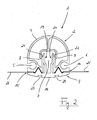
- FIG. 2 the strut 1 of the invention FIG. 1 , wherein the profile parts 2, 3 are in their assembled state. This will be discussed in more detail below.
- the first profile item 2 is formed as a hollow profile part and has at its top a cross-sectionally approximately semicircular outer contour 4, to which a laterally outwardly opening recess or groove 5 or 6 connects on both sides in the manner of a piping rail. Furthermore, the first profiled item 2 has a central recess 7 whose cross-section is widened laterally towards the inside, so that paragraphs 8, 9 result, whose function will be discussed in more detail below.
- the grooves 5, 6 have according to the embodiment shown and without limiting the generality of a substantially circular cross-section.
- the first profiled individual part 2 On its underside, that is to say the rounded outer contour 4, the first profiled individual part 2 has a structured joining surface 10, whose design and function will be discussed in more detail below.
- the second profile item 3 is initially formed relatively flat or with only a slight curvature of its outer contour 14.
- the second profile individual part 3 is designed for positive cooperation with the first profile individual part 2 and accordingly has longitudinal projections 16, 17 on its joining surface 15 facing the first profile part 2, which projections are complementary to the longitudinal recesses 11, 12 of the first profile individual part 2. Laterally of the longitudinal projections 16, 17 are recessed areas of the second profile item 3, of which FIG. 1 only one is explicitly designated 18, which are complementary to the said projections 13 formed on the joining surface 10 of the first profile item 2.
- the second profile individual part 3 has two latching projections 19, 20 which extend essentially parallel to one another and each have a latching nose 21 or 22 at their free end, which in a manner known per se when assembling the profile parts 2, 3 with the already mentioned Paragraphs 8, 9 of the central recess 7 of the first profile item 2 cooperate to lock the two profile items 2, 3 together.
- the first profile item 2 is pressed in the direction of the arrow P on the second profile item 3, whereupon further below with reference to FIG. 2 will be discussed in more detail.
- the second profile item 3 has on its longitudinal projections 16, 17 and the latching projections 19, 20 opposite bottom in the region of the outer contour 14 dovetailed undercut recesses 23, 24, on the function below with reference to FIG. 3 will be discussed in more detail.
- each lanes a pool cover, which are held clamped to produce a complete pool cover on the strut 1 should.
- said cover webs 25, 26 in the region of the longitudinal projections 16, 17 of the second profile item 3 in the according to FIG. 1 remaining space between the first profile item 2 and the lower profile item 3 is introduced.
- the profile parts 2, 3 are locked together, as described, and it results in the FIG. 2 exemplified configuration.
- FIG. 2 For the sake of clarity, not all of the above are based on the FIG. 1 described individual features of the strut 1 explicitly designated, otherwise the same reference numerals indicate the same or equivalent elements.
- FIG. 2 engage in the assembled state of the first profile item 2 and the second profile item 3, the locking lugs 21, 22 of the locking projections 19 and 20 behind the paragraphs 8, 9 in the central recess 7, so that the two profile items 2, 3 safely together are locked.
- the profile parts 2, 3 engage at their respective joining surfaces 10 and 15 with the in FIG. 2 for reasons of clarity unspecified projections and recesses 11, 12, 13, 16, 17, 18 (see. FIG. 1 ) form fit into each other, so that the Abdeckplanenbahnen 25, 26 are clamped between the profile parts 2, 3, without for this purpose the corresponding edges of the webs 25, 26 would be prepared in any way.
- a suitable tool as shown in FIG. 1 or FIG. 2 perpendicular to the plane of the sheet are engaged in the central recess to press the locking projections 19, 20 toward each other and then deduct the first profile item 2 of the second profile item 3.
- FIG. 3 shows on the basis of a perspective overall view again an embodiment of the strut 1 according to the invention with the first 2 and second profile item 3, wherein between the latter in turn Abdeckplanenbahnen 25, 26 are clamped.
- the edge region of the strut 1 the edge of a swimming pool to be covered is indicated by means of a dashed line R, the water-filled area of the swimming pool to be covered being designated symbolically by the reference numeral 27.
- Reference numerals 28, 29 designate end pieces or end caps for closing the strut 1 at their open ends.
- the end caps 28, 29 have a planar shape which corresponds geometrically substantially to the common outer contour 4, 14 of the first 2 and second profile individual part 3 (cf. FIGS. 1 and 2 ).
- the end caps 28, 29 have integrally formed pins 30 which engage in the profile parts 2, 3 for holding the end caps 28, 29 on the strut 1. This preferably takes place in the region of the grooves 5, 6 and in the region between the outer contour 4 of the first profile individual part 2 and a central recess 7 of the defining, unspecified inner structure of the first profile individual part 2 (cf. FIG. 1 or FIG. 2 ).
- a plate-shaped edge support member 31 which with correspondingly shaped projections which in FIG. 3 are not visible, in the recesses 23, 24 according to FIG. 1 or FIG. 2 intervenes.
- the edge support member 31 is inserted from the end of the strut 1 ago with said projections in the recesses 23, 24.
- the edge support member 31 is suitably made of a relatively soft material, preferably plastic, and can be easily replaced if necessary or wear.
- the Abdeckplanenbahnen 25, 26 can basically have any desired dimension perpendicular to the extension of the strut 1. Conveniently, however, one will select a standard width of production engineering, for example 1.3 m, for the stated width and accordingly provide a strut 1 according to the invention approximately every 1.3 m. Only at the beginning and / or end of the cover is then adapted to the basin, narrower track needed. A whatsoever connection of webs, be it by welding, sewing or the like, is not required in this way and greatly simplifies the production and handling of the swimming pool cover thus created.
- FIG. 4 also shows a perspective view of a further embodiment of the strut 1 according to the invention, which in turn for clamping holding two Abdeckplanenbahnen 25, 26 composed of a first profile item 2 and a second profile item 3, as described above in detail.
- the strut 1 has an identical end cap 29 as in FIG FIG. 3 on.
- the end cap or the end piece 32 at the other end of the strut 1 is different from the embodiment in FIG FIG. 3 trained, which is discussed in more detail below.
- the end piece 32 in turn engages with molded pins or pins 30 in the grooves 5, 6 of the first profile item 2 a.
- the end piece 32 further integrally formed insertion means 33 for insertion into the first profile single part 2, the shape of which are at least partially complementary to the inner dimensions of - as mentioned - designed as a hollow profile first profile single part 2.
- the actual end piece body 34 which remains outside the strut 1 or the first profile individual part 2 and which is preferably formed in plastic with a cast-in square shaft 35, adjoins said structures 30, 33, the latter being connected to a (motor-driven or manual) Roll-up device for the pool cover is used.
- the bracing of the swimming pool cover thus created is thus carried out exclusively on the struts 1, so that incorporation of tension straps or the like in the tarpaulin itself is not required.
- FIG. 5 shows an end portion of a strut 1 according to the invention with the first 2 and second profile item 3, in the present case for reasons of clarity, no Abdeckplanenbahnen between the profile parts 2, 3 are clamped.
- the strut 1 is also suitable for a comparison with the representation in the Figures 3 and 4 inverted use, that is, with down to the tank interior 27 turned towards first profile item. 2
- a specially designed end piece 39 is provided, which with structures 30, 33 analogous to the end piece 32 according to FIG. 4 engages in the strut 1.
- longitudinal recesses 42 are again provided in this area, as cooperate with corresponding projections 43 of a substantially plate-shaped cover part 44 in order to connect the cover part 44 to the end piece 39.
- the cover 44 has on its upper side a curvature approximately corresponding to the outer contour of the second profile element 3, such as the one shown in FIG FIG. 5 is hinted at.
Landscapes
- Engineering & Computer Science (AREA)
- Architecture (AREA)
- General Engineering & Computer Science (AREA)
- Civil Engineering (AREA)
- Structural Engineering (AREA)
- Mechanical Engineering (AREA)
- Tents Or Canopies (AREA)
Priority Applications (1)
| Application Number | Priority Date | Filing Date | Title |
|---|---|---|---|
| EP08008473A EP2116671A1 (fr) | 2008-05-06 | 2008-05-06 | barre pour une couverture de piscine |
Applications Claiming Priority (1)
| Application Number | Priority Date | Filing Date | Title |
|---|---|---|---|
| EP08008473A EP2116671A1 (fr) | 2008-05-06 | 2008-05-06 | barre pour une couverture de piscine |
Publications (1)
| Publication Number | Publication Date |
|---|---|
| EP2116671A1 true EP2116671A1 (fr) | 2009-11-11 |
Family
ID=39709210
Family Applications (1)
| Application Number | Title | Priority Date | Filing Date |
|---|---|---|---|
| EP08008473A Withdrawn EP2116671A1 (fr) | 2008-05-06 | 2008-05-06 | barre pour une couverture de piscine |
Country Status (1)
| Country | Link |
|---|---|
| EP (1) | EP2116671A1 (fr) |
Cited By (3)
| Publication number | Priority date | Publication date | Assignee | Title |
|---|---|---|---|---|
| EP2374964A1 (fr) | 2010-04-09 | 2011-10-12 | Bieri Alpha Covers AG | Entretoise pour une couverture de piscine |
| EP2426287A3 (fr) * | 2010-08-18 | 2014-10-29 | Sunprotex BVBA | Porte-toile pour stores à rouleau |
| EP3482981A1 (fr) * | 2017-11-08 | 2019-05-15 | Schmitz Cargobull AG | Structure de bâche et unité de bâche pour un véhicule utilitaire |
Citations (7)
| Publication number | Priority date | Publication date | Assignee | Title |
|---|---|---|---|---|
| GB1542812A (en) * | 1977-07-07 | 1979-03-28 | Boalloy Ltd | Van bodies |
| CH675445A5 (fr) | 1988-10-11 | 1990-09-28 | Glatz Ag | |
| EP0465430B1 (fr) | 1990-07-06 | 1995-02-15 | Bieri Blachen Ag | Couverture de piscine |
| DE69311940T2 (de) | 1992-03-23 | 1998-01-22 | Philips Electronics Nv | Anzeigevorrichtung mit Bildröhre einschlisslich einer Kaltkathode |
| FR2765606A1 (fr) * | 1997-07-07 | 1999-01-08 | Procopi | Poutrelle de support pour un caillebotis de piscine enterree |
| WO2004009933A1 (fr) * | 2002-07-18 | 2004-01-29 | Pooltechnics B.V. | Dispositif de couverture et barre de maintien associee |
| EP1564346A1 (fr) * | 2004-02-13 | 2005-08-17 | Procopi | Couverture pour un bassin tel qu'une piscine, procédé et installation pour l'assemblage d'une telle couverture |
-
2008
- 2008-05-06 EP EP08008473A patent/EP2116671A1/fr not_active Withdrawn
Patent Citations (7)
| Publication number | Priority date | Publication date | Assignee | Title |
|---|---|---|---|---|
| GB1542812A (en) * | 1977-07-07 | 1979-03-28 | Boalloy Ltd | Van bodies |
| CH675445A5 (fr) | 1988-10-11 | 1990-09-28 | Glatz Ag | |
| EP0465430B1 (fr) | 1990-07-06 | 1995-02-15 | Bieri Blachen Ag | Couverture de piscine |
| DE69311940T2 (de) | 1992-03-23 | 1998-01-22 | Philips Electronics Nv | Anzeigevorrichtung mit Bildröhre einschlisslich einer Kaltkathode |
| FR2765606A1 (fr) * | 1997-07-07 | 1999-01-08 | Procopi | Poutrelle de support pour un caillebotis de piscine enterree |
| WO2004009933A1 (fr) * | 2002-07-18 | 2004-01-29 | Pooltechnics B.V. | Dispositif de couverture et barre de maintien associee |
| EP1564346A1 (fr) * | 2004-02-13 | 2005-08-17 | Procopi | Couverture pour un bassin tel qu'une piscine, procédé et installation pour l'assemblage d'une telle couverture |
Cited By (3)
| Publication number | Priority date | Publication date | Assignee | Title |
|---|---|---|---|---|
| EP2374964A1 (fr) | 2010-04-09 | 2011-10-12 | Bieri Alpha Covers AG | Entretoise pour une couverture de piscine |
| EP2426287A3 (fr) * | 2010-08-18 | 2014-10-29 | Sunprotex BVBA | Porte-toile pour stores à rouleau |
| EP3482981A1 (fr) * | 2017-11-08 | 2019-05-15 | Schmitz Cargobull AG | Structure de bâche et unité de bâche pour un véhicule utilitaire |
Similar Documents
| Publication | Publication Date | Title |
|---|---|---|
| DE4133144A1 (de) | Aufpralltraeger | |
| DE102011121381B4 (de) | Verfahren zur Herstellung eines Aufprallquerträgers sowie Aufprallquerträger | |
| EP2116671A1 (fr) | barre pour une couverture de piscine | |
| EP2851225B1 (fr) | Structure de véhicule utilitaire doté de bâche latérale, véhicule utilitaire avec une telle structure et procédé de fabrication d'une telle structure de véhicule utilitaire | |
| DE102013012386A1 (de) | Plane | |
| EP2374964A1 (fr) | Entretoise pour une couverture de piscine | |
| WO2014154441A1 (fr) | Dispositif de montage pour un élément d'habillage de paroi latérale d'un véhicule ferroviaire | |
| DE202012103447U1 (de) | Rollenlaufschiene für einen Kamerawagen | |
| DE202005009924U1 (de) | Schalung zum Herstellen eines im Querschnitt runden Betonbauteils | |
| DE202008010516U1 (de) | Seitenplane für ein Nutzfahrzeug und Nutzfahrzeug mit einer derartigen Seitenplane | |
| DE102011122189B4 (de) | Windschott | |
| DE2744757A1 (de) | Verfahren zur anbringung von lageraugen an schwenkbar zu lagernden konstruktionsteilen, insbesondere scharnierfluegeln | |
| EP2990325A1 (fr) | Stabilisateur a aileron, procede et navire | |
| DE202015101585U1 (de) | Faltkajak | |
| DE3400322A1 (de) | Vorrichtung zur herstellung von monolithischen, wenigstens einseitig offenen, insbesondere glockenfoermigen und mit ihrer offenen seite nach unten weisenden stahlbetonraumzellen | |
| DE102013219317B4 (de) | Verfahren zur Herstellung einer Fahrzeugkarosserie und Fahrzeugkarosserie | |
| DE102007047439A1 (de) | Schalungsanrodnung für den Freivorbau von Brücken | |
| EP0547467B1 (fr) | Tambour pour câbles en matériau composite avec flasques constitués de segments amovibles | |
| DE2610729B2 (de) | Vorrichtung zur Herstellung von Schalensitzlehnen | |
| DE202008008250U1 (de) | Eckverbinder | |
| DE3000103C2 (de) | Vorrichtung zum Führen eines Zugmittels mit mehreren das jeweilige Zugmitteltrum- ziehendes Trum und/oder Leertrum -führenden Rollen | |
| DE112008002875B4 (de) | Versteifungselement für die Fahrzeugkarosserie | |
| DE102007016152B4 (de) | Windschott für einen PKW | |
| DE102014014101B4 (de) | Überdachungsschirm und Errichtungsverfahren | |
| DE202022102312U1 (de) | Öffenbares Seitenplanenwandsystem |
Legal Events
| Date | Code | Title | Description |
|---|---|---|---|
| PUAI | Public reference made under article 153(3) epc to a published international application that has entered the european phase |
Free format text: ORIGINAL CODE: 0009012 |
|
| AK | Designated contracting states |
Kind code of ref document: A1 Designated state(s): AT BE BG CH CY CZ DE DK EE ES FI FR GB GR HR HU IE IS IT LI LT LU LV MC MT NL NO PL PT RO SE SI SK TR |
|
| AX | Request for extension of the european patent |
Extension state: AL BA MK RS |
|
| AKX | Designation fees paid | ||
| STAA | Information on the status of an ep patent application or granted ep patent |
Free format text: STATUS: THE APPLICATION IS DEEMED TO BE WITHDRAWN |
|
| 18D | Application deemed to be withdrawn |
Effective date: 20100512 |
|
| REG | Reference to a national code |
Ref country code: DE Ref legal event code: 8566 |