EP2116671A1 - support beam for a swimming pool cover - Google Patents
support beam for a swimming pool cover Download PDFInfo
- Publication number
- EP2116671A1 EP2116671A1 EP08008473A EP08008473A EP2116671A1 EP 2116671 A1 EP2116671 A1 EP 2116671A1 EP 08008473 A EP08008473 A EP 08008473A EP 08008473 A EP08008473 A EP 08008473A EP 2116671 A1 EP2116671 A1 EP 2116671A1
- Authority
- EP
- European Patent Office
- Prior art keywords
- strut
- profile
- cover
- tarpaulin
- item
- Prior art date
- Legal status (The legal status is an assumption and is not a legal conclusion. Google has not performed a legal analysis and makes no representation as to the accuracy of the status listed.)
- Withdrawn
Links
- 230000009182 swimming Effects 0.000 title claims description 24
- 239000000463 material Substances 0.000 claims description 13
- 238000005304 joining Methods 0.000 claims description 9
- 230000000295 complement effect Effects 0.000 claims description 8
- 229920006255 plastic film Polymers 0.000 claims description 8
- 239000002985 plastic film Substances 0.000 claims description 7
- XLYOFNOQVPJJNP-UHFFFAOYSA-N water Substances O XLYOFNOQVPJJNP-UHFFFAOYSA-N 0.000 claims description 7
- 239000004753 textile Substances 0.000 claims description 6
- 238000003780 insertion Methods 0.000 claims description 3
- 230000037431 insertion Effects 0.000 claims description 3
- XAGFODPZIPBFFR-UHFFFAOYSA-N aluminium Chemical compound [Al] XAGFODPZIPBFFR-UHFFFAOYSA-N 0.000 claims description 2
- 229910052782 aluminium Inorganic materials 0.000 claims description 2
- 238000004519 manufacturing process Methods 0.000 description 11
- 238000011161 development Methods 0.000 description 9
- 230000018109 developmental process Effects 0.000 description 9
- 239000004033 plastic Substances 0.000 description 4
- 238000013461 design Methods 0.000 description 2
- 238000012549 training Methods 0.000 description 2
- 238000003466 welding Methods 0.000 description 2
- 230000015572 biosynthetic process Effects 0.000 description 1
- 239000013039 cover film Substances 0.000 description 1
- 238000005520 cutting process Methods 0.000 description 1
- 230000007423 decrease Effects 0.000 description 1
- 239000004744 fabric Substances 0.000 description 1
- 230000002349 favourable effect Effects 0.000 description 1
- 238000010348 incorporation Methods 0.000 description 1
- 230000009191 jumping Effects 0.000 description 1
- 239000012528 membrane Substances 0.000 description 1
- 238000012545 processing Methods 0.000 description 1
- 239000002990 reinforced plastic Substances 0.000 description 1
- 230000002787 reinforcement Effects 0.000 description 1
- 230000003014 reinforcing effect Effects 0.000 description 1
- 238000005096 rolling process Methods 0.000 description 1
- 238000009958 sewing Methods 0.000 description 1
- 239000007779 soft material Substances 0.000 description 1
- 230000000007 visual effect Effects 0.000 description 1
Images


Classifications
-
- E—FIXED CONSTRUCTIONS
- E04—BUILDING
- E04H—BUILDINGS OR LIKE STRUCTURES FOR PARTICULAR PURPOSES; SWIMMING OR SPLASH BATHS OR POOLS; MASTS; FENCING; TENTS OR CANOPIES, IN GENERAL
- E04H4/00—Swimming or splash baths or pools
- E04H4/06—Safety devices; Coverings for baths
- E04H4/10—Coverings of flexible material
-
- F—MECHANICAL ENGINEERING; LIGHTING; HEATING; WEAPONS; BLASTING
- F16—ENGINEERING ELEMENTS AND UNITS; GENERAL MEASURES FOR PRODUCING AND MAINTAINING EFFECTIVE FUNCTIONING OF MACHINES OR INSTALLATIONS; THERMAL INSULATION IN GENERAL
- F16B—DEVICES FOR FASTENING OR SECURING CONSTRUCTIONAL ELEMENTS OR MACHINE PARTS TOGETHER, e.g. NAILS, BOLTS, CIRCLIPS, CLAMPS, CLIPS OR WEDGES; JOINTS OR JOINTING
- F16B5/00—Joining sheets or plates, e.g. panels, to one another or to strips or bars parallel to them
- F16B5/06—Joining sheets or plates, e.g. panels, to one another or to strips or bars parallel to them by means of clamps or clips
- F16B5/0692—Joining sheets or plates, e.g. panels, to one another or to strips or bars parallel to them by means of clamps or clips joining flexible sheets to other sheets or plates or to strips or bars
-
- E—FIXED CONSTRUCTIONS
- E04—BUILDING
- E04F—FINISHING WORK ON BUILDINGS, e.g. STAIRS, FLOORS
- E04F10/00—Sunshades, e.g. Florentine blinds or jalousies; Outside screens; Awnings or baldachins
- E04F10/02—Sunshades, e.g. Florentine blinds or jalousies; Outside screens; Awnings or baldachins of flexible canopy materials, e.g. canvas ; Baldachins
- E04F10/06—Sunshades, e.g. Florentine blinds or jalousies; Outside screens; Awnings or baldachins of flexible canopy materials, e.g. canvas ; Baldachins comprising a roller-blind with means for holding the end away from a building
- E04F10/0633—Arrangements for fastening the flexible canopy material to the supporting structure
-
- E—FIXED CONSTRUCTIONS
- E06—DOORS, WINDOWS, SHUTTERS, OR ROLLER BLINDS IN GENERAL; LADDERS
- E06B—FIXED OR MOVABLE CLOSURES FOR OPENINGS IN BUILDINGS, VEHICLES, FENCES OR LIKE ENCLOSURES IN GENERAL, e.g. DOORS, WINDOWS, BLINDS, GATES
- E06B9/00—Screening or protective devices for wall or similar openings, with or without operating or securing mechanisms; Closures of similar construction
- E06B9/24—Screens or other constructions affording protection against light, especially against sunshine; Similar screens for privacy or appearance; Slat blinds
- E06B9/40—Roller blinds
- E06B9/42—Parts or details of roller blinds, e.g. suspension devices, blind boxes
- E06B9/44—Rollers therefor; Fastening roller blinds to rollers
- E06B9/46—Rollers therefor; Fastening roller blinds to rollers by clamping bars
Definitions
- the present invention relates to a strut according to the preamble of claim 1 for covering an opening or depression, in particular for a swimming pool cover with a cover, in particular a textile plastic film, like a safety cover, wherein the strut for supporting the tarpaulin over the opening or recess and in particular over the water-filled area of a swimming pool is provided.
- the present invention relates to a cover according to the preamble of claim 14, in particular a swimming pool cover, with a tarpaulin in the manner of a safety cover.
- Covers in particular swimming pool covers of the type mentioned and corresponding struts for this purpose are known.
- Such (swimming pool) covers can also be described as roll protection, since the tarpaulin, which is provided, for example, for covering the water-filled area of a swimming pool, is rolled up together with the supporting (transverse) struts when the swimming pool is used and accordingly is not covered.
- a required bracing of the pool cover according to EP 0 465 430 B1 is achieved by the fact that the longitudinal edges of the swimming pool cover reinforced executed and in particular folded over and welded for this purpose. For tensioning straps are hung in eyelets on the cover itself and tightened accordingly.
- the said reinforcement of the edge regions of the cover is relatively complicated and cost-intensive, with the required weldability of the material in turn entailing restrictions in the choice of material.
- a covering device for a pool in particular for a swimming pool is known in which parts of the cover so-called Querlieken comprise, as they are known, for example, of ship sails, said Lieken are mounted in corresponding recesses of the cross braces, in order to achieve a continuous Cover to produce cross struts and Abdeckfolien matter.
- Querlieken comprises, as they are known, for example, of ship sails
- said Lieken are mounted in corresponding recesses of the cross braces, in order to achieve a continuous Cover to produce cross struts and Abdeckfolien constitution.
- the formation of said Lieken is associated with an increased manufacturing effort.
- the repair of damaged cover film parts is correspondingly complex, especially in the case of damage to the deck, which must be laboriously repaired or completely replaced in order to continue to use the proposed pool cover.
- the invention has for its object to provide a strut for covering an opening or depression with a tarpaulin, in particular a textile plastic film, as well as a cover formed by means of such struts, which give the above-mentioned disadvantages of the prior art, which avoids the above-mentioned disadvantages of the prior art and is in particular easier and less expensive to produce, in this context, in particular as possible should be no restrictions on the choice of materials to be used for the tarpaulin.
- the invention solves this problem by means of a strut for covering an opening or depression with the features of patent claim 1 and by means of a cover with the features of claim 14.
- a strut for the cover of an opening or depression with a tarpaulin, in particular a textile plastic film, wherein the strut for supporting the tarpaulin over the opening or recess, in particular over the water-filled area of a swimming pool is provided, characterized in that the strut is formed as a multi-part profile element, form from the individual parts at least a first and a second in the assembled state, a clamping device for clamping the tarpaulin.
- a basic idea of the present invention is that essentially no (costly) complex changes to the covering tarpaulin are necessary for connecting the struts to the covering tarpaulin of a covering, as in the case of the pockets provided according to the prior art Lieken was the case regularly.
- Lieken was the case regularly.
- the edges of cover panel parts can be easily inserted between said individual parts of the multi-part strut profile element, which are then joined together and clamp said cover panel parts between them.
- a whatsoever edge processing of Abdeckplanenmaschine is basically not required, which reduces the manufacturing cost and also makes virtually any tarpaulin materials for the production of the cover usable.
- the clamped Abdeckplanenmaschine basically after opening the profile element can be removed from this and replaced in a simple manner, it is even possible to cut off only a damaged area of the respective Abdeckplanenteils and then clamp this again between the individual parts of the profile element.
- the strut profile element according to the invention is preferably designed with respect to the profile individual parts such that when they are joined together a sufficiently strong spring action is produced which prevents a clamped tarpaulin from being pulled out of the profile element without difficulty. It is advantageously guaranteed at least a tensile strength of about 4 kg / 10 cm, which corresponds to the weight of a person of about 80 kg.
- a first development of the strut according to the invention provides that for clamping the tarpaulin, the first profile individual part and the second profile individual part are locked together, including one of said profile items at least one locking recess and the other profile individual part has at least one corresponding latching projection.
- first profile item and the second profile item for removal the tarpaulin are in particular substantially non-destructively separable from each other.
- one of the profile parts has a rounded outer contour, in particular a part-circular cross-section.
- the other profile part may have a relatively flat outer contour in relation to the rounded profile part mentioned.
- the necessary for security bracing a pool cover according to the prior art takes place on the tarpaulin itself, for which purpose it is formed reinforced in a correspondingly complex manner.
- another preferred development of the strut according to the invention provides that the first profile individual part and / or the second profile individual part has at least one groove which is formed along the extension of the respective profile individual part and into which sliding blocks with an eyelet structure for hooking in tension straps can be introduced. In this way, the bracing of the (swimming pool) cover takes place directly on their struts, so that even in the edge regions of the tarpaulin no complex and costly training of reinforcing structures is required.
- the said grooves are each arranged on the edge of the outer contour of the rounded Profileinzelteils.
- first profile individual part and the second profile individual part at their joining surfaces, that is, those surfaces which face each other in the assembled state of the profile element, complementary structures, which serve to clamp the tarpaulin.
- the said complementary structures comprise, for example, at least one longitudinal recess with a particular triangular or frusto-conical cross section on the first or second profile individual part and a correspondingly complementary longitudinal projection on the other profile individual part.
- the first profile individual part and / or the second profile individual part may be formed on at least one end as a profile hollow part, wherein an end piece is provided for the particular common closing of the profile individual parts at the corresponding end.
- the closing can be done in particular by inserting said end piece in the profile item or in the profile items, in particular by plugging into the groove mentioned above.
- one of the profile parts on its outer surface relative to the joined state of the strut has at least one mounting structure to which an edge support part of the cover can be fastened.
- the aforementioned attachment structure may be, in particular, an undercut longitudinal recess.
- the end piece mentioned above which is plugged into the same for closing the profile individual part or the profile parts, may have a structure which serves for connection to a drive unit for the cover, in particular a square wave structure.
- the strut itself rests on said edge, but that the end piece inserted into the strut has a support surface for laying on an edge of the opening or recess.
- the struts themselves are preferably formed in aluminum or a comparable material, the end piece or the above-mentioned edge support part may be formed, for example, in plastic, so that it can be replaced easily and without great expense in the event of damage by friction on the edge.
- a development of the cover according to the invention is characterized by a substantially regular sequence of tarpaulin membranes or divide and struts according to the invention, wherein the width of the Abdeckplanenbahnen in particular about 1.3 m, which may optionally be used on the edge of the cover webs with different width.
- Such a configuration is particularly advantageous because the tarpaulin material used is typically only available in certain widths on the market, so that the described regular sequence of Abdeckplanenbahnen and struts on which the tarpaulin material according to the invention - as described - is clamped, only one Cutting the Abdeckplanenmaterials to the desired (pool) width is required.
- just as many struts according to the invention are used to cover the opening or depression that, when using standard-width cover strips, a substantially complete covering of the opening or depression results. Only in the edge region, it will then be necessary to provide a Abdeckplanenbahn with deviating, usually smaller width.
- novel cover described above thus represents a favorable alternative to existing models and can be produced for these reasons without special manufacturing machines, such as high frequency or hot air machines.
- the production is thus substantially independent of a particular manufacturing location in an advantageous manner.
- FIG. 1 shows a cross section through a strut according to the invention for a pool cover, wherein the strut in its entirety designated by the reference numeral 1 and moreover not to the present purely by way of example said use is limited to cover a swimming pool, but can be used to cover virtually any openings and depressions.
- the strut 1 is designed as a multi-part profile element and according to the embodiment shown, consists of two profile individual parts 2, 3, which in the present case are also referred to as first profile individual part 2 or second profile individual part 3 without restricting generality.
- FIG. 1 the profile items 2, 3 are shown in the separated state.
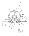
- FIG. 2 the strut 1 of the invention FIG. 1 , wherein the profile parts 2, 3 are in their assembled state. This will be discussed in more detail below.
- the first profile item 2 is formed as a hollow profile part and has at its top a cross-sectionally approximately semicircular outer contour 4, to which a laterally outwardly opening recess or groove 5 or 6 connects on both sides in the manner of a piping rail. Furthermore, the first profiled item 2 has a central recess 7 whose cross-section is widened laterally towards the inside, so that paragraphs 8, 9 result, whose function will be discussed in more detail below.
- the grooves 5, 6 have according to the embodiment shown and without limiting the generality of a substantially circular cross-section.
- the first profiled individual part 2 On its underside, that is to say the rounded outer contour 4, the first profiled individual part 2 has a structured joining surface 10, whose design and function will be discussed in more detail below.
- the second profile item 3 is initially formed relatively flat or with only a slight curvature of its outer contour 14.
- the second profile individual part 3 is designed for positive cooperation with the first profile individual part 2 and accordingly has longitudinal projections 16, 17 on its joining surface 15 facing the first profile part 2, which projections are complementary to the longitudinal recesses 11, 12 of the first profile individual part 2. Laterally of the longitudinal projections 16, 17 are recessed areas of the second profile item 3, of which FIG. 1 only one is explicitly designated 18, which are complementary to the said projections 13 formed on the joining surface 10 of the first profile item 2.
- the second profile individual part 3 has two latching projections 19, 20 which extend essentially parallel to one another and each have a latching nose 21 or 22 at their free end, which in a manner known per se when assembling the profile parts 2, 3 with the already mentioned Paragraphs 8, 9 of the central recess 7 of the first profile item 2 cooperate to lock the two profile items 2, 3 together.
- the first profile item 2 is pressed in the direction of the arrow P on the second profile item 3, whereupon further below with reference to FIG. 2 will be discussed in more detail.
- the second profile item 3 has on its longitudinal projections 16, 17 and the latching projections 19, 20 opposite bottom in the region of the outer contour 14 dovetailed undercut recesses 23, 24, on the function below with reference to FIG. 3 will be discussed in more detail.
- each lanes a pool cover, which are held clamped to produce a complete pool cover on the strut 1 should.
- said cover webs 25, 26 in the region of the longitudinal projections 16, 17 of the second profile item 3 in the according to FIG. 1 remaining space between the first profile item 2 and the lower profile item 3 is introduced.
- the profile parts 2, 3 are locked together, as described, and it results in the FIG. 2 exemplified configuration.
- FIG. 2 For the sake of clarity, not all of the above are based on the FIG. 1 described individual features of the strut 1 explicitly designated, otherwise the same reference numerals indicate the same or equivalent elements.
- FIG. 2 engage in the assembled state of the first profile item 2 and the second profile item 3, the locking lugs 21, 22 of the locking projections 19 and 20 behind the paragraphs 8, 9 in the central recess 7, so that the two profile items 2, 3 safely together are locked.
- the profile parts 2, 3 engage at their respective joining surfaces 10 and 15 with the in FIG. 2 for reasons of clarity unspecified projections and recesses 11, 12, 13, 16, 17, 18 (see. FIG. 1 ) form fit into each other, so that the Abdeckplanenbahnen 25, 26 are clamped between the profile parts 2, 3, without for this purpose the corresponding edges of the webs 25, 26 would be prepared in any way.
- a suitable tool as shown in FIG. 1 or FIG. 2 perpendicular to the plane of the sheet are engaged in the central recess to press the locking projections 19, 20 toward each other and then deduct the first profile item 2 of the second profile item 3.
- FIG. 3 shows on the basis of a perspective overall view again an embodiment of the strut 1 according to the invention with the first 2 and second profile item 3, wherein between the latter in turn Abdeckplanenbahnen 25, 26 are clamped.
- the edge region of the strut 1 the edge of a swimming pool to be covered is indicated by means of a dashed line R, the water-filled area of the swimming pool to be covered being designated symbolically by the reference numeral 27.
- Reference numerals 28, 29 designate end pieces or end caps for closing the strut 1 at their open ends.
- the end caps 28, 29 have a planar shape which corresponds geometrically substantially to the common outer contour 4, 14 of the first 2 and second profile individual part 3 (cf. FIGS. 1 and 2 ).
- the end caps 28, 29 have integrally formed pins 30 which engage in the profile parts 2, 3 for holding the end caps 28, 29 on the strut 1. This preferably takes place in the region of the grooves 5, 6 and in the region between the outer contour 4 of the first profile individual part 2 and a central recess 7 of the defining, unspecified inner structure of the first profile individual part 2 (cf. FIG. 1 or FIG. 2 ).
- a plate-shaped edge support member 31 which with correspondingly shaped projections which in FIG. 3 are not visible, in the recesses 23, 24 according to FIG. 1 or FIG. 2 intervenes.
- the edge support member 31 is inserted from the end of the strut 1 ago with said projections in the recesses 23, 24.
- the edge support member 31 is suitably made of a relatively soft material, preferably plastic, and can be easily replaced if necessary or wear.
- the Abdeckplanenbahnen 25, 26 can basically have any desired dimension perpendicular to the extension of the strut 1. Conveniently, however, one will select a standard width of production engineering, for example 1.3 m, for the stated width and accordingly provide a strut 1 according to the invention approximately every 1.3 m. Only at the beginning and / or end of the cover is then adapted to the basin, narrower track needed. A whatsoever connection of webs, be it by welding, sewing or the like, is not required in this way and greatly simplifies the production and handling of the swimming pool cover thus created.
- FIG. 4 also shows a perspective view of a further embodiment of the strut 1 according to the invention, which in turn for clamping holding two Abdeckplanenbahnen 25, 26 composed of a first profile item 2 and a second profile item 3, as described above in detail.
- the strut 1 has an identical end cap 29 as in FIG FIG. 3 on.
- the end cap or the end piece 32 at the other end of the strut 1 is different from the embodiment in FIG FIG. 3 trained, which is discussed in more detail below.
- the end piece 32 in turn engages with molded pins or pins 30 in the grooves 5, 6 of the first profile item 2 a.
- the end piece 32 further integrally formed insertion means 33 for insertion into the first profile single part 2, the shape of which are at least partially complementary to the inner dimensions of - as mentioned - designed as a hollow profile first profile single part 2.
- the actual end piece body 34 which remains outside the strut 1 or the first profile individual part 2 and which is preferably formed in plastic with a cast-in square shaft 35, adjoins said structures 30, 33, the latter being connected to a (motor-driven or manual) Roll-up device for the pool cover is used.
- the bracing of the swimming pool cover thus created is thus carried out exclusively on the struts 1, so that incorporation of tension straps or the like in the tarpaulin itself is not required.
- FIG. 5 shows an end portion of a strut 1 according to the invention with the first 2 and second profile item 3, in the present case for reasons of clarity, no Abdeckplanenbahnen between the profile parts 2, 3 are clamped.
- the strut 1 is also suitable for a comparison with the representation in the Figures 3 and 4 inverted use, that is, with down to the tank interior 27 turned towards first profile item. 2
- a specially designed end piece 39 is provided, which with structures 30, 33 analogous to the end piece 32 according to FIG. 4 engages in the strut 1.
- longitudinal recesses 42 are again provided in this area, as cooperate with corresponding projections 43 of a substantially plate-shaped cover part 44 in order to connect the cover part 44 to the end piece 39.
- the cover 44 has on its upper side a curvature approximately corresponding to the outer contour of the second profile element 3, such as the one shown in FIG FIG. 5 is hinted at.
Abstract
Description
Die vorliegende Erfindung betrifft eine Strebe nach dem Oberbegriff des Patentanspruchs 1 für die Abdeckung einer Öffnung oder Vertiefung, insbesondere für eine Schwimmbadabdeckung mit einer Abdeckplane, insbesondere einer textilen Kunststofffolie, nach Art einer Sicherheitsabdeckung, wobei die Strebe zum Tragen der Abdeckplane über der Öffnung oder Vertiefung und insbesondere über dem Wasser gefüllten Bereich eines Schwimmbeckens vorgesehen ist.The present invention relates to a strut according to the preamble of
Weiterhin betrifft die vorliegende Erfindung eine Abdeckung nach dem Oberbegriff des Patentanspruchs 14, insbesondere eine Schwimmbadabdeckung, mit einer Abdeckplane nach Art einer Sicherheitsabdeckung.Furthermore, the present invention relates to a cover according to the preamble of
Abdeckungen, insbesondere Schwimmbadabdeckungen der eingangs genannten Art und entsprechende Streben hierfür sind bekannt. Derartige (Schwimmbad-)Abdeckungen lassen sich auch als Rollschutz bezeichnen, da die Abdeckplane, die beispielsweise zum Abdecken des Wasser gefüllten Bereichs eines Schwimmbads vorgesehen ist, zusammen mit den sie tragenden (Quer-)Streben eingerollt wird, wenn das Schwimmbad benutzt wird und dementsprechend nicht abgedeckt ist.Covers, in particular swimming pool covers of the type mentioned and corresponding struts for this purpose are known. Such (swimming pool) covers can also be described as roll protection, since the tarpaulin, which is provided, for example, for covering the water-filled area of a swimming pool, is rolled up together with the supporting (transverse) struts when the swimming pool is used and accordingly is not covered.
Aus der
Eine erforderliche Verspannbarkeit der Schwimmbadabdeckung gemäß
Auch beim Gegenstand der
Aus der
Der Erfindung liegt die Aufgabe zugrunde, eine Strebe für eine Abdeckung einer Öffnung oder Vertiefung mit einer Abdeckplane, insbesondere einer textilen Kunststofffolie, sowie eine mit Hilfe solcher Streben gebildete Abdeckung anzugeben, welche die oben genannten Nachteile des Standes der Technik verzugeben, welche die oben genannten Nachteile des Standes der Technik vermeidet und dabei insbesondere einfacher und kostengünstiger herstellbar ist, wobei in diesem Zusammenhang insbesondere möglichst keine Beschränkungen bei der Wahl von für die Abdeckplane zu verwendenden Materialien bestehen soll.The invention has for its object to provide a strut for covering an opening or depression with a tarpaulin, in particular a textile plastic film, as well as a cover formed by means of such struts, which give the above-mentioned disadvantages of the prior art, which avoids the above-mentioned disadvantages of the prior art and is in particular easier and less expensive to produce, in this context, in particular as possible should be no restrictions on the choice of materials to be used for the tarpaulin.
Die Erfindung löst diese Aufgabe mittels einer Strebe für die Abdeckung einer Öffnung oder Vertiefung mit den Merkmalen des Patentanspruchs 1 sowie mittels einer Abdeckung mit den Merkmalen des Patentanspruchs 14.The invention solves this problem by means of a strut for covering an opening or depression with the features of
Vorteilhafte Weiterbildungen der Erfindung sind jeweils Gegenstand von Unteransprüchen, deren Wortlaut hiermit durch ausdrückliche Bezugnahme in die Beschreibung aufgenommen wird, um unnötige Textwiederholungen zu vermeiden.Advantageous developments of the invention are the subject of subclaims, the wording of which is hereby included by express reference in the description in order to avoid unnecessary text repetitions.
Erfindungsgemäß ist eine Strebe für die Abdeckung einer Öffnung oder Vertiefung mit einer Abdeckplane, insbesondere einer textilen Kunststofffolie, wobei die Strebe zum Tragen der Abdeckplane über der Öffnung oder Vertiefung, insbesondere über dem Wasser gefüllten Bereich eines Schwimmbeckens vorgesehen ist, dadurch gekennzeichnet, dass die Strebe als mehrteiliges Profilelement ausgebildet ist, von dessen Einzelteilen wenigstens ein erstes und ein zweites im zusammengefügten Zustand eine Klemmvorrichtung zum Klemmen der Abdeckplane bilden.According to the invention a strut for the cover of an opening or depression with a tarpaulin, in particular a textile plastic film, wherein the strut for supporting the tarpaulin over the opening or recess, in particular over the water-filled area of a swimming pool is provided, characterized in that the strut is formed as a multi-part profile element, form from the individual parts at least a first and a second in the assembled state, a clamping device for clamping the tarpaulin.
Entsprechend ist eine erfindungsgemäße Abdeckung mit einer Abdeckplane, insbesondere einer textilen Kunststofffolie, gekennzeichnet durch wenigstens eine erfindungsgemäße Strebe, wobei die Strebe zum Tragen der Abdeckplane über einer Öffnung oder Vertiefung und insbesondere über dem Wasser gefüllten Bereich eines Schwimmbeckens vorgesehen ist.Accordingly, a cover according to the invention with a tarpaulin, in particular a textile plastic film, characterized by at least one strut according to the invention, wherein the strut for supporting the tarpaulin over an opening or depression and in particular over the water-filled area of a swimming pool is provided.
Ein Grundgedanke der vorliegenden Erfindung ist demnach darin zu sehen, dass zum Verbinden der Streben mit der Abdeckplane einer Abdeckung im Wesentlichen keine (kosten-)aufwändigen Veränderungen an der Abdeckplane erforderlich sind, wie das bei der Ausbildung der nach dem Stand der Technik vorgesehenen Taschen oder Lieken regelmäßig der Fall war. Vorliegend erfolgt durch Klemmen der Abdeckplane zwischen den Einzelteilen eines mehrteiligen Profilelements, welches die erfindungsgemäße Strebe bildet.Accordingly, a basic idea of the present invention is that essentially no (costly) complex changes to the covering tarpaulin are necessary for connecting the struts to the covering tarpaulin of a covering, as in the case of the pockets provided according to the prior art Lieken was the case regularly. In the present case by clamping the tarpaulin between the individual parts of a multi-part profile element, which forms the strut according to the invention.
Erfindungsgemäß lassen sich die Ränder von Abdeckplanenteilen einfach zwischen die genannten Einzelteile des mehrteiligen Streben-Profilelements einlegen, welche anschließend zusammengefügt werden und die genannten Abdeckplanenteile zwischen sich einklemmen. Eine wie auch immer geartete Randbearbeitung der Abdeckplanenteile ist dabei grundsätzlich nicht erforderlich, was die Herstellungskosten reduziert und darüber hinaus quasi beliebige Planenmaterialien zur Herstellung der Abdeckung nutzbar macht.According to the invention, the edges of cover panel parts can be easily inserted between said individual parts of the multi-part strut profile element, which are then joined together and clamp said cover panel parts between them. A whatsoever edge processing of Abdeckplanenteile is basically not required, which reduces the manufacturing cost and also makes virtually any tarpaulin materials for the production of the cover usable.
Zu Reparaturzwecken lassen sich die geklemmten Abdeckplanenteile grundsätzlich nach Öffnen des Profilelements aus diesem entnehmen und in einfacher Weise ersetzen, wobei sogar möglich ist, nur einen beschädigten Bereich des jeweiligen Abdeckplanenteils abzuschneiden und dieses anschließend wieder zwischen den Einzelteilen des Profilelements einzuklemmen.For repair purposes, the clamped Abdeckplanenteile basically after opening the profile element can be removed from this and replaced in a simple manner, it is even possible to cut off only a damaged area of the respective Abdeckplanenteils and then clamp this again between the individual parts of the profile element.
Das erfindungsgemäße Streben-Profilelement ist bezogen auf die Profileinzelteile vorzugsweise derart ausgebildet, dass bei deren Zusammenfügen eine hinreichend starke Federwirkung erzeugt wird, die verhindert, dass eine geklemmte Abdeckplane aus dem Profilelement ohne weiteres herausgezogen werden kann. Dabei wird vorteilhafter Weise mindestens eine Zugfestigkeit von etwa 4 kg/10 cm garantiert, was der Gewichtskraft einer Person von ca. 80 kg entspricht.The strut profile element according to the invention is preferably designed with respect to the profile individual parts such that when they are joined together a sufficiently strong spring action is produced which prevents a clamped tarpaulin from being pulled out of the profile element without difficulty. It is advantageously guaranteed at least a tensile strength of about 4 kg / 10 cm, which corresponds to the weight of a person of about 80 kg.
Eine erste Weiterbildung der erfindungsgemäßen Strebe sieht vor, dass zum Klemmen der Abdeckplane das erste Profileinzelteil und das zweite Profileinzelteil miteinander verrastet werden, wozu eines der genannten Profileinzelteile wenigstens eine Rastausnehmung und das andere Profileinzelteil zumindest einen entsprechenden Rastvorsprung aufweist.A first development of the strut according to the invention provides that for clamping the tarpaulin, the first profile individual part and the second profile individual part are locked together, including one of said profile items at least one locking recess and the other profile individual part has at least one corresponding latching projection.
Um die weiter oben erwähnte Austauschbarkeit von Abdeckplanenteilen zu erreichen, sieht eine andere Weiterbildung der erfindungsgemäßen Strebe vor, dass das erste Profileinzelteil und das zweite Profileinzelteil zum Entnehmen der Abdeckplane insbesondere im Wesentlichen zerstörungsfrei voneinander trennbar sind.In order to achieve the above-mentioned interchangeability of Abdeckplanenteilen, provides another embodiment of the strut according to the invention that the first profile item and the second profile item for removal the tarpaulin are in particular substantially non-destructively separable from each other.
Aus ästhetischen Gründen sowie zum Zwecke einer besseren Rollbarkeit sieht eine andere Weiterbildung der erfindungsgemäßen Strebe vor, dass eines der Profileinzelteile eine abgerundete, im Querschnitt insbesondere teilkreisförmige Außenkontur aufweist. Dagegen kann das andere Profilteil bezogen auf das genannte abgerundete Profilteil eine relativ ebene Außenkontur aufweisen.For aesthetic reasons, as well as for the purpose of better rollability, another development of the strut according to the invention provides that one of the profile parts has a rounded outer contour, in particular a part-circular cross-section. In contrast, the other profile part may have a relatively flat outer contour in relation to the rounded profile part mentioned.
Wie oben erwähnt, erfolgt die aus Sicherheitsgründen notwendige Verspannung einer Schwimmbadabdeckung nach dem Stand der Technik an der Abdeckplane selbst, wozu diese in entsprechend aufwändiger Weise verstärkt ausgebildet ist. Dagegen sieht eine andere bevorzugte Weiterbildung der erfindungsgemäßen Strebe vor, dass das erste Profileinzelteil und/oder das zweite Profileinzelteil wenigstens eine Nut aufweist, die längs der Erstreckung des jeweiligen Profileinzelteils ausgebildet ist und in die sich Nutensteine mit einer Ösenstruktur zum Einhaken von Spanngurten einbringen lassen. Auf diese Weise erfolgt die Verspannung der (Schwimmbad-)Abdeckung direkt an deren Streben, so dass auch in den Randbereichen der Abdeckplane keine aufwändige und kostenintensive Ausbildung von Verstärkungsstrukturen erforderlich ist.As mentioned above, the necessary for security bracing a pool cover according to the prior art takes place on the tarpaulin itself, for which purpose it is formed reinforced in a correspondingly complex manner. By contrast, another preferred development of the strut according to the invention provides that the first profile individual part and / or the second profile individual part has at least one groove which is formed along the extension of the respective profile individual part and into which sliding blocks with an eyelet structure for hooking in tension straps can be introduced. In this way, the bracing of the (swimming pool) cover takes place directly on their struts, so that even in the edge regions of the tarpaulin no complex and costly training of reinforcing structures is required.
Vorzugsweise sind die genannten Nuten jeweils am Rand der Außenkontur des abgerundeten Profileinzelteils angeordnet.Preferably, the said grooves are each arranged on the edge of the outer contour of the rounded Profileinzelteils.
Vorteilhafterweise weisen das erste Profileinzelteil und das zweite Profileinzelteil an ihren Fügeflächen, das heißt denjenigen Flächen, die im zusammengefügten Zustand des Profilelements einander zugewandt sind, komplementäre Strukturen auf, die zum Klemmen der Abdeckplane dienen.Advantageously, the first profile individual part and the second profile individual part at their joining surfaces, that is, those surfaces which face each other in the assembled state of the profile element, complementary structures, which serve to clamp the tarpaulin.
Die genannten komplementären Strukturen umfassen beispielsweise wenigstens eine Längsausnehmung mit insbesondere dreieckförmigem oder kegelstumpfförmigem Querschnitt an dem ersten oder zweiten Profileinzelteil und einen entsprechend komplementären Längsvorsprung an dem anderen Profileinzelteil.The said complementary structures comprise, for example, at least one longitudinal recess with a particular triangular or frusto-conical cross section on the first or second profile individual part and a correspondingly complementary longitudinal projection on the other profile individual part.
Das erste Profileinzelteil und/oder das zweite Profileinzelteil können an wenigstens einem Ende als Profilhohlteil ausgebildet sein, wobei ein Endstück zum insbesondere gemeinsamen Verschließen der Profileinzelteile an dem entsprechenden Ende vorgesehen ist. Das Verschließen kann insbesondere durch Einstecken des genannten Endstücks in das Profileinzelteil bzw. in die Profileinzelteile erfolgen, insbesondere durch Einstecken in die weiter oben genannte Nut.The first profile individual part and / or the second profile individual part may be formed on at least one end as a profile hollow part, wherein an end piece is provided for the particular common closing of the profile individual parts at the corresponding end. The closing can be done in particular by inserting said end piece in the profile item or in the profile items, in particular by plugging into the groove mentioned above.
Um Abnutzungen der Strebe bei Bewegungen über den Rand der abzudeckenden Öffnung oder Vertiefung, z.B. über den Beckenrand eines Schwimmbeckens zu vermeiden, sieht eine andere Weiterbildung der erfindungsgemäßen Strebe vor, dass eines der Profileinzelteile an seiner Außenfläche bezogen auf den zusammengefügten Zustand der Strebe wenigstens eine Befestigungsstruktur aufweist, an der ein Randauflageteil der Abdeckung befestigbar ist. Bei der genannten Befestigungsstruktur kann es sich insbesondere um eine hinterschnittene Längsausnehmung handeln.To prevent wear of the strut during movements over the edge of the opening or depression to be covered, e.g. To avoid over the pool edge of a swimming pool, another development of the strut according to the invention provides that one of the profile parts on its outer surface relative to the joined state of the strut has at least one mounting structure to which an edge support part of the cover can be fastened. The aforementioned attachment structure may be, in particular, an undercut longitudinal recess.
Das weiter oben genannte Endstück, welches zum Verschließen des Profileinzelteils bzw. der Profileinzelteile in dieselben eingesteckt wird, kann im Zuge einer anderen Weiterbildung der Erfindung eine Struktur aufweisen, die zum Verbinden mit einer Antriebseinheit für die Abdeckung dient, insbesondere eine Kantwellenstruktur.In the course of another development of the invention, the end piece mentioned above, which is plugged into the same for closing the profile individual part or the profile parts, may have a structure which serves for connection to a drive unit for the cover, in particular a square wave structure.
Im Zuge einer anderen Weiterbildung der vorliegenden Erfindung kann auch vorgesehen sein, dass nicht die Strebe selbst auf dem genannten Rand aufliegt, sondern dass das in die Strebe eingesetzte Endstück eine Auflagefläche zum Auflegen auf einen Rand der Öffnung oder Vertiefung aufweist. Während die Streben selbst vorzugsweise in Aluminium oder einem vergleichbaren Werkstoff ausgebildet sind, kann das Endstück oder das weiter oben genannte Randauflageteil beispielsweise in Kunststoff ausgebildet sein, so dass es im Falle einer Beschädigung durch Reibung auf dem Rand leicht und ohne größeren Kostenaufwand ersetzbar ist.In the course of another development of the present invention can also be provided that not the strut itself rests on said edge, but that the end piece inserted into the strut has a support surface for laying on an edge of the opening or recess. While the struts themselves are preferably formed in aluminum or a comparable material, the end piece or the above-mentioned edge support part may be formed, for example, in plastic, so that it can be replaced easily and without great expense in the event of damage by friction on the edge.
Eine Weiterbildung der erfindungsgemäßen Abdeckung zeichnet sich durch eine im Wesentlichen regelmäßige Abfolge von Abdeckplanenbahnen oder - teilen und erfindungsgemäßen Streben aus, wobei die Breite der Abdeckplanenbahnen insbesondere ca. 1,3 m beträgt, wobei gegebenenfalls am Rand der Abdeckung Bahnen mit abweichender Breite verwendet werden können.A development of the cover according to the invention is characterized by a substantially regular sequence of tarpaulin membranes or divide and struts according to the invention, wherein the width of the Abdeckplanenbahnen in particular about 1.3 m, which may optionally be used on the edge of the cover webs with different width.
Eine derartige Ausgestaltung ist insbesondere deshalb besonders vorteilhaft, weil das verwendete Abdeckplanenmaterial am Markt typischerweise nur in bestimmten Breiten verfügbar ist, so dass durch die beschriebene regelmäßige Abfolge von Abdeckplanenbahnen und Streben, an denen das Abdeckplanenmaterial erfindungsgemäß - wie beschrieben - klemmend gehalten ist, lediglich ein Zuschneiden des Abdeckplanenmaterials auf die gewünschte (Becken-)Breite erforderlich ist. Mit anderen Worten, im Zuge der beschriebenen Weiterbildung der vorliegenden Erfindung werden zum Abdecken der Öffnung oder Vertiefung eben so viele erfindungsgemäße Streben verwendet, dass sich bei Verwendung von Abdeckplanenbahnen mit Standardbreite gerade eine im Wesentlichen vollständige Abdeckung der Öffnung oder Vertiefung ergibt. Lediglich im Randbereich wird es dann erforderlich sein, eine Abdeckplanenbahn mit abweichender, in der Regel geringerer Breite vorzusehen.Such a configuration is particularly advantageous because the tarpaulin material used is typically only available in certain widths on the market, so that the described regular sequence of Abdeckplanenbahnen and struts on which the tarpaulin material according to the invention - as described - is clamped, only one Cutting the Abdeckplanenmaterials to the desired (pool) width is required. In other words, in the course of the described development of the present invention, just as many struts according to the invention are used to cover the opening or depression that, when using standard-width cover strips, a substantially complete covering of the opening or depression results. Only in the edge region, it will then be necessary to provide a Abdeckplanenbahn with deviating, usually smaller width.
Die vorstehend beschriebene neuartige Abdeckung stellt somit eine günstige Alternative zu bestehenden Modellen dar und lässt sich aus den genannten Gründen ohne spezielle Fabrikationsmaschinen, wie Hochfrequenz- oder Heißluftmaschinen, herstellen. Die Herstellung wird somit in vorteilhafter Weise von einem bestimmten Fabrikationsstandort im Wesentlichen unabhängig.The novel cover described above thus represents a favorable alternative to existing models and can be produced for these reasons without special manufacturing machines, such as high frequency or hot air machines. The production is thus substantially independent of a particular manufacturing location in an advantageous manner.
Durch die beschriebene Austauschbarkeit von Abdeckplanenbahnen ergibt sich eine einfache Reparierbarkeit der vorgeschlagenen Abdeckung.The described interchangeability of Abdeckplanenbahnen results in a simple reparability of the proposed cover.
Da die Abspannung - wie beschrieben - nur noch an den Streben selbst erfolgt, ist keine kostenintensive Ausbildung von Kedern längs am Rollschutz mehr erforderlich.Since the bracing - as described - only takes place on the struts themselves, no costly training of piping along the roll protection is more necessary.
Insgesamt wird die Fertigung des erfindungsgemäßen Rollschutzes von der Stoffqualität und dem verwendeten Werkstoff grundsätzlich unabhängig.Overall, the production of the rolling protection according to the invention of the material quality and the material used is basically independent.
Durch das erfindungsgemäße Klemmen der Abdeckplanenbahnen muss das entsprechende Material nur noch auf die korrekte Länge zugeschnitten werden; ein Schweißen von Taschen, Kedern oder dergleichen ist nicht mehr erforderlich.Due to the inventive clamping the Abdeckplanenbahnen the appropriate material must be cut only to the correct length; Welding of bags, piping or the like is no longer required.
Durch die beschriebene Abspannung der Abdeckung an den Streben selbst müssen vorteilhafterweise an der Abdeckplane keine Abspannungen angeschweißt werden. Wenn zudem die Befestigungsstrukturen für die Abspannung aufgrund der genannten Nutensteine längs der Streben verschiebbar, ergibt sich auch hinsichtlich der Abspannpositionen am Rand der Öffnung oder Vertiefung eine größtmögliche Flexibilität ergibt.Due to the described bracing of the cover to the struts itself no braces must advantageously be welded to the tarpaulin. In addition, if the attachment structures for the bracing due to said sliding blocks along the struts displaced, also results in terms of the guy positions at the edge of the opening or depression maximum flexibility results.
Durch das beschriebene Vorsehen eines Auflageschutzes an den Streben lässt sich deren Lebensdauer quasi nach Belieben verlängern.The described provision of a support protection on the struts, their life can quasi extend at will.
Weitere Eigenschaften und Vorteile der vorliegenden Erfindung ergeben sich aus der nachfolgenden Beschreibung von Ausführungsbeispielen anhand der Zeichnung. Es zeigt:
Figur 1- eine Querschnittsansicht einer erfindungsgemäßen Strebe speziell für eine Schwimmbadabdeckung im getrennten Zustand ihrer Einzelteile;
Figur 2- die Strebe aus
Figur 1 Figur 3- eine zusammengefügte, erfindungsgemäße Strebe mit Endstücken, Randauflage und geklemmten Abdeckplanenbahnen;
Figur 4- eine zusammengefügte, erfindungsgemäße Strebe im Wesentlichen gemäß
Figur 3 Figur 5- eine Teilansicht eines Endbereichs einer erfindungsgemäßen Strebe mit zugehörigem Endstück.
- FIG. 1
- a cross-sectional view of a strut according to the invention especially for a pool cover in the separated state of their individual parts;
- FIG. 2
- the strut off
FIG. 1 in the assembled state of your items and with clamped tarpaulin; - FIG. 3
- an assembled strut according to the invention with end pieces, edge support and clamped Abdeckplanenbahnen;
- FIG. 4
- an assembled strut according to the invention substantially according to
FIG. 3 with fastening means for a tensioning device; and - FIG. 5
- a partial view of an end portion of a strut according to the invention with associated tail.
Die Strebe 1 ist als mehrteiliges Profilelement ausgebildet und besteht gemäß der gezeigten Ausführungsform aus zwei Profileinzelteilen 2, 3, die vorliegend ohne Beschränkung der Allgemeinheit auch als erstes Profileinzelteil 2 bzw. zweites Profileinzelteil 3 bezeichnet werden.The
In der Darstellung gemäß
Das erste Profileinzelteil 2 ist als Hohlprofilteil ausgebildet und weist an seiner Oberseite eine im Querschnitt in etwa halbkreisförmige Außenkontur 4 auf, an die sich auf beiden Seiten eine seitlich nach außen öffnende Ausnehmung oder Nut 5 bzw. 6 nach Art einer Kederschiene anschließt. Weiterhin weist das erste Profileinzelteil 2 eine zentrale Ausnehmung 7 auf, deren Querschnitt nach innen hin seitlich verbreitert ist, so dass Absätze 8, 9 resultieren, auf deren Funktion weiter unten noch genauer eingegangen wird.The
Die Nuten 5, 6 weisen gemäß dem gezeigten Ausführungsbeispiel und ohne Beschränkung der Allgemeinheit einen im Wesentlichen kreisförmigen Querschnitt auf.The
An seiner Unterseite, das heißt der abgerundeten Außenkontur 4 gegenüberliegend weist das erste Profileinzelteil 2 eine strukturierte Fügefläche 10 auf, auf deren Ausgestaltung und Funktion nachfolgend noch genauer eingegangen wird.On its underside, that is to say the rounded
Links und rechts der zentralen Ausnehmung 7 sind an der Fügefläche 10 Längsausnehmungen 11, 12 mit im Wesentlichen dreieckförmigem Querschnitt ausgebildet, wobei Kanten der Längsausnehmungen 11, 12, von denen in
Verglichen mit dem ersten Profileinzelteil 2 ist das zweite Profileinzelteil 3 zunächst relativ eben bzw. mit einer nur leichten Krümmung seiner Außenkontur 14 ausgebildet.Compared with the
Das zweite Profileinzelteil 3 ist zum formschlüssigen Zusammenwirken mit dem ersten Profileinzelteil 2 ausgebildet und weist demnach an seiner dem ersten Profilteil 2 zugewandten Fügefläche 15 Längsvorsprünge 16, 17 auf, welche zu den Längsausnehmungen 11, 12 des ersten Profileinzelteils 2 komplementär ausgebildet sind. Seitlich der Längsvorsprünge 16, 17 finden sich rückspringende Bereiche des zweiten Profileinzelteils 3, von denen in
Weiterhin weist das zweite Profileinzelteil 3 zwei sich im Wesentlichen parallel zueinander erstreckende Rastvorsprünge 19, 20 auf, die an ihrem freien Ende jeweils eine Rastnase 21 bzw. 22 aufweisen, die beim Zusammenfügen der Profileinzelteile 2, 3 in an sich bekannter Weise mit dem bereits erwähnten Absätzen 8, 9 der zentralen Ausnehmung 7 des ersten Profileinzelteils 2 zusammenwirken, um die beiden Profileinzelteile 2, 3 miteinander zu verrasten. Zu diesem Zweck wird das erste Profileinzelteil 2 in Richtung des Pfeils P auf das zweite Profileinzelteil 3 aufgedrückt, worauf weiter unten anhand der
Das zweite Profileinzelteil 3 weist an seiner den Längsvorsprüngen 16, 17 und den Rastvorsprüngen 19, 20 abgewandten Unterseite im Bereich der Außenkontur 14 schwalbenschwanzartig hinterschnittene Ausnehmungen 23, 24 auf, auf deren Funktion weiter unten anhand von
Weiterhin sind in
In
Wie der
Es kann weiterhin vorgesehen sein, die beiden Profileinzelteile 2, 3 derart auszubilden bzw. ein entsprechendes Werkzeug (nicht gezeigt) vorzusehen, dass die Verrastung aufgehoben und die beiden Profileinzelteile 2, 3 wieder voneinander getrennt werden können, beispielsweise um die Stoffbahnen 25, 26 bei Beschädigung austauschen zu können. Beispielsweise kann zu diesem Zweck mit einem geeigneten Werkzeug gemäß der Darstellung in
Wie der Fachmann erkennt, ist die Erfindung jedoch keinesfalls auf die vorstehend exemplarisch beschriebenen Ausgestaltungen insbesondere der Fügeflächen 10, 15, des Rastmechanismus und/oder der Außenkonturen 4, 14 beschränkt.However, as the person skilled in the art will recognize, the invention is in no way limited to the embodiments described in exemplary manner in particular of the joining
Bezugszeichen 28, 29 bezeichnen Endstücke oder Endkappen zum Verschließen der Strebe 1 an ihren offenen Enden. Entsprechend weisen die Endkappen 28, 29 eine flächige Formgebung auf, die geometrisch im Wesentlichen der gemeinsamen Außenkontur 4, 14 des ersten 2 und zweiten Profileinzelteils 3 entspricht (vgl.
Um die Strebe 1 gegen Beschädigung durch Reibung auf dem Beckenrand R zu schützen, ist gemäß
Die Abdeckplanenbahnen 25, 26 können grundsätzlich jede gewünschte Abmessung senkrecht zur Erstreckung der Strebe 1 aufweisen. Zweckmäßigerweise wird man für die genannte Breite jedoch eine fertigungstechnische Normbreite, beispielsweise 1,3 m, wählen und entsprechend etwa alle 1,3 m eine erfindungsgemäße Strebe 1 vorsehen. Nur am Anfang und/oder Ende der Abdeckung wird dann eine an das Becken angepasste, schmalere Bahn benötigt. Ein wie auch immer geartetes Verbinden von Bahnen, sei es durch Verschweißen, Vernähen oder dergleichen, ist auf diese Weise nicht erforderlich und vereinfacht die Herstellung und Handhabung der so geschaffenen Schwimmbadabdeckung enorm.The
An ihrem einen Ende weist die Strebe 1 eine identische Endkappe 29 wie in
Das Endstück 32 greift wiederum mit angeformten Stiften oder Zapfen 30 in die Nuten 5, 6 des ersten Profileinzelteils 2 ein. Darüber hinaus weist das Endstück 32 weitere angeformte Einsteckmittel 33 zum Einstecken in das erste Profileinzelteil 2 auf, deren Formgebung zumindest teilweise komplementär zu den Innenabmessungen des - wie gesagt - als Hohlprofil ausgebildeten ersten Profileinzelteils 2 ausgebildet sind. An die genannten Strukturen 30, 33 schließt sich der eigentliche Endstückkörper 34 an, welcher außerhalb der Strebe 1 bzw. des ersten Profileinzelteils 2 verbleibt und der vorzugsweise in Kunststoff mit eingegossener Vierkantwelle 35 ausgebildet ist, wobei letztere zum Verbinden mit einer (motorbetriebenen oder manuellen) Aufrollvorrichtung für die Schwimmbadabdeckung dient.The
Bei der Ausführungsform gemäß
Das Verspannen der so geschaffenen Schwimmbadabdeckung erfolgt somit ausschließlich über die Streben 1, so dass ein Einarbeiten von Spanngurten oder dergleichen in die Abdeckplane selbst nicht erforderlich ist. Darüber hinaus kann vorteilhafterweise an quasi beliebigen Stellen der Strebe 1 die Verspannung erfolgen.The bracing of the swimming pool cover thus created is thus carried out exclusively on the
Gemäß der Darstellung in
Zu diesem Zweck ist ein besonders ausgebildetes Endstück 39 vorgesehen, welches mit Strukturen 30, 33 analog zu dem Endstück 32 gemäß
Aus optisch-ästhetischen Gründen weist das Abdeckteil 44 an seiner Oberseite eine etwa der Außenkontur des zweiten Profileinzelteils 3 entsprechende Krümmung auf, wie der
Gemäß der Ausgestaltung in
Claims (15)
dadurch gekennzeichnet,
dass die Strebe (1) als mehrteiliges Profilelement ausgebildet ist, von dessen Einzelteilen wenigstens ein erstes (2) und ein zweites (3) im zusammengefügten Zustand eine Klemmvorrichtung zum Klemmen der Abdeckplane (25, 26) bilden.Strut (1) for covering an opening or depression with a tarpaulin (25, 26), in particular a textile plastic film, in particular for a pool cover, wherein the strut (1) for supporting the tarpaulin (25, 26) in particular filled over the water Area (27) of a swimming pool is provided,
characterized,
in that the strut (1) is designed as a multi-part profiled element, of the individual parts of which at least a first (2) and a second (3) in the assembled state form a clamping device for clamping the covering tarpaulin (25, 26).
dadurch gekennzeichnet,
dass das erste (2) und das zweite Profileinzelteil (3) zum Klemmen der Abdeckplane (25, 26) miteinander verrastet sind.Strut (1) according to claim 1,
characterized,
in that the first (2) and the second profile individual part (3) for clamping the cover tarpaulin (25, 26) are latched together.
dadurch gekennzeichnet,
dass das erste Profileinzelteil (2) eine abgerundete, im Querschnitt insbesondere teilkreisförmige Außenkontur (4) aufweist.Strut (1) according to claim 1 or claim 2,
characterized,
in that the first profile individual part (2) has a rounded outer contour (4) which is in particular part-circular in cross-section.
dadurch gekennzeichnet,
dass das zweite Profileinzelteil (3) bezogen auf den zusammengefügten Zustand der Strebe (1) eine insbesondere bezogen auf das erste Profileinzelteil (2) relativ ebene Außenkontur (14) aufweist.Strut (1) according to at least one of claims 1 to 3,
characterized,
that the second profile item (3) relative to the assembled condition of the strut (1) a particular with respect to the first profile item (2) relatively planar outer contour (14).
dadurch gekennzeichnet,
dass das erste Profileinzelteil (2) und/oder das zweite Profileinzelteil (3) wenigstens eine Nut (5, 6) aufweist, die längs der Erstreckung des jeweiligen Profileinzelteils (2, 3) ausgebildet ist.Strut (1) according to at least one of claims 1 to 4,
characterized,
that the first profile item (2) and / or the second profile item (3) at least one groove (5, 6) which is formed along the extension of the respective profile item (2, 3).
dadurch gekennzeichnet,
dass das erste Profileinzelteil (2) und das zweite Profileinzelteil (3) an ihren Fügeflächen (10, 15), die im zusammengefügten Zustand einander zugewandt sind, komplementäre Strukturen (11, 12, 13, 16, 17, 18) zum Klemmen der Abdeckplane (25, 26) aufweisen.Strut (1) according to at least one of claims 1 to 5,
characterized,
in that the first profile element (2) and the second profile individual part (3) have complementary structures (11, 12, 13, 16, 17, 18) for clamping the cover tarpaulin at their joining surfaces (10, 15) which face one another in the assembled state (25, 26).
dadurch gekennzeichnet,
dass zum Klemmen der Abdeckplane (25, 26) an dem ersten (2) oder zweiten Profileinzelteil (3) wenigstens eine Längsausnehmung (11, 12, 18) mit insbesondere dreieckförmigem oder kegelstumpfförmigem Querschnitt und an dem anderen Profileinzelteil (2, 3) wenigstens ein entsprechend komplementärer Längsvorsprung (13, 16, 17) vorgesehen ist.Strut (1) according to at least one of claims 1 to 6,
characterized,
in that for clamping the cover tarpaulin (25, 26) on the first (2) or second profile individual part (3) at least one longitudinal recess (11, 12, 18) with in particular triangular or frusto-conical cross-section and at the other profile individual part (2, 3) at least one corresponding complementary longitudinal projection (13, 16, 17) is provided.
dadurch gekennzeichnet,
dass das erste Profileinzelteil (2) und/oder das zweite Profileinzelteil (3) an wenigstens einem Ende als Hohlprofilteil ausgebildet ist und dass ein Endstück (28, 29, 32, 39) zum insbesondere gemeinsamen Verschließen des Profileinzelteils bzw. der Profileinzelteile vorgesehen ist, insbesondere durch Einstecken in das Profileinzelteil bzw. in die Profileinzelteile, insbesondere in die Nut (5, 6) gemäß Anspruch 5.Strut (1) according to at least one of claims 1 to 7,
characterized,
that the first profile item (2) and / or the second profile item (3) is formed at least at one end as a hollow profile part and that an end piece (28, 29, 32, 39) for in particular common closing the profile single part or of the profiled parts is provided, in particular by insertion into the profile individual part or into the profile individual parts, in particular into the groove (5, 6) according to claim 5.
dadurch gekennzeichnet,
dass das Endstück (28, 29, 32, 39) eine Struktur (35), insbesondere Kantstabstruktur zum Verbinden mit einer Antriebseinheit für die Abdeckung aufweist.Strut (1) according to claim 8,
characterized,
that the end piece (28, 29, 32, 39) has a structure (35), in particular square rod structure for connecting with a drive unit for the cover.
dadurch gekennzeichnet,
dass das Endstück (28, 29, 32, 39) eine Auflagefläche (41) zum Auflegen auf einen Rand (R) der Öffnung oder Vertiefung, insbesondere des Schwimmbeckens aufweist.Strut (1) according to claim 8 or 9,
characterized,
that comprises the end portion (28, 29, 32, 39) has a bearing surface (41) for laying on a rim (R) of the opening or depression, particularly of the swimming pool.
dadurch gekennzeichnet,
dass das zweite Profileinzelteil (3) an seiner Außenfläche bezogen auf den zusammengefügten Zustand wenigstens eine Befestigungsstruktur (23, 24), insbesondere eine hinterschnittene Längsausnehmung aufweist, an der ein Randauflageteil (31) befestigt bzw. befestigbar ist.Strut (1) at least according to claim 4,
characterized,
includes that the second profile item (3) based on its outer surface to the assembled state at least one mounting structure (23, 24), in particular an undercut longitudinal recess, attached to an edge of supporting part (31) or can be attached.
dadurch gekennzeichnet,
dass in die Nut (5, 6) eine Anzahl von Nutensteinen (36) eingesetzt bzw. einsetzbar ist, welche eine insbesondere um eine Längsachse des Nutensteins (36) schwenkbare Ösenstruktur (37) zum Einhaken einer Spannvorrichtung (38) für die Abdeckung aufweisen.Strut (1) according to at least claim 6,
characterized,
in that a number of sliding blocks (36) are inserted into the groove (5, 6) and have an eyelet structure (37) which can be swiveled around a longitudinal axis of the sliding block (36) for hooking in a clamping device (38) for the cover.
dadurch gekennzeichnet,
dass die Strebe (1) in Aluminium oder einem vergleichbaren Werkstoff ausgebildet ist.Strut (1) according to at least one of claims 1 to 12,
characterized,
that the strut (1) is formed in aluminum or a comparable material.
Kunststofffolie, gekennzeichnet durch wenigstens eine Strebe (1) nach mindestens einem der Ansprüche 1 bis 13 zum Tragen der Abdeckplane (25, 26) über einer Öffnung oder Vertiefung, insbesondere über dem wassergefüllten Bereich (27) eines Schwimmbeckens.Cover with a tarpaulin (25, 26), in particular a textile
Plastic film, characterized by at least one strut (1) according to at least one of claims 1 to 13 for supporting the cover tarpaulin (25, 26) over an opening or depression, in particular above the water-filled area (27) of a swimming pool.
regelmäßige Abfolge von Abdeckplanenbahnen (25, 26) und Streben (1), wobei die Breite der Abdeckplanenbahnen (25, 26) gegebenenfalls mit Ausnahme des Abdeckplanenrandes insbesondere ca. 1,3 m beträgt.Cover according to claim 14, characterized by a preferably
regular sequence of Abdeckplanenbahnen (25, 26) and struts (1), wherein the width of the Abdeckplanenbahnen (25, 26), if appropriate, with the exception of the Abdeckplanenrandes in particular about 1.3 m.
Priority Applications (1)
| Application Number | Priority Date | Filing Date | Title |
|---|---|---|---|
| EP08008473A EP2116671A1 (en) | 2008-05-06 | 2008-05-06 | support beam for a swimming pool cover |
Applications Claiming Priority (1)
| Application Number | Priority Date | Filing Date | Title |
|---|---|---|---|
| EP08008473A EP2116671A1 (en) | 2008-05-06 | 2008-05-06 | support beam for a swimming pool cover |
Publications (1)
| Publication Number | Publication Date |
|---|---|
| EP2116671A1 true EP2116671A1 (en) | 2009-11-11 |
Family
ID=39709210
Family Applications (1)
| Application Number | Title | Priority Date | Filing Date |
|---|---|---|---|
| EP08008473A Withdrawn EP2116671A1 (en) | 2008-05-06 | 2008-05-06 | support beam for a swimming pool cover |
Country Status (1)
| Country | Link |
|---|---|
| EP (1) | EP2116671A1 (en) |
Cited By (3)
| Publication number | Priority date | Publication date | Assignee | Title |
|---|---|---|---|---|
| EP2374964A1 (en) | 2010-04-09 | 2011-10-12 | Bieri Alpha Covers AG | Strut for a swimming pool cover |
| EP2426287A3 (en) * | 2010-08-18 | 2014-10-29 | Sunprotex BVBA | Fabric holder for roller blinds |
| EP3482981A1 (en) * | 2017-11-08 | 2019-05-15 | Schmitz Cargobull AG | Canvas cover and canvas unit for a commercial vehicle |
Citations (7)
| Publication number | Priority date | Publication date | Assignee | Title |
|---|---|---|---|---|
| GB1542812A (en) * | 1977-07-07 | 1979-03-28 | Boalloy Ltd | Van bodies |
| CH675445A5 (en) | 1988-10-11 | 1990-09-28 | Glatz Ag | |
| EP0465430B1 (en) | 1990-07-06 | 1995-02-15 | Bieri Blachen Ag | Swimming-pool cover |
| DE69311940T2 (en) | 1992-03-23 | 1998-01-22 | Philips Electronics Nv | Display device with picture tube including a cold cathode |
| FR2765606A1 (en) * | 1997-07-07 | 1999-01-08 | Procopi | Girder to support grating around edge of swimming pool |
| WO2004009933A1 (en) * | 2002-07-18 | 2004-01-29 | Pooltechnics B.V. | Covering construction, and support beam therefor |
| EP1564346A1 (en) * | 2004-02-13 | 2005-08-17 | Procopi | Swimming pool cover, method and installation for assembling such a cover |
-
2008
- 2008-05-06 EP EP08008473A patent/EP2116671A1/en not_active Withdrawn
Patent Citations (7)
| Publication number | Priority date | Publication date | Assignee | Title |
|---|---|---|---|---|
| GB1542812A (en) * | 1977-07-07 | 1979-03-28 | Boalloy Ltd | Van bodies |
| CH675445A5 (en) | 1988-10-11 | 1990-09-28 | Glatz Ag | |
| EP0465430B1 (en) | 1990-07-06 | 1995-02-15 | Bieri Blachen Ag | Swimming-pool cover |
| DE69311940T2 (en) | 1992-03-23 | 1998-01-22 | Philips Electronics Nv | Display device with picture tube including a cold cathode |
| FR2765606A1 (en) * | 1997-07-07 | 1999-01-08 | Procopi | Girder to support grating around edge of swimming pool |
| WO2004009933A1 (en) * | 2002-07-18 | 2004-01-29 | Pooltechnics B.V. | Covering construction, and support beam therefor |
| EP1564346A1 (en) * | 2004-02-13 | 2005-08-17 | Procopi | Swimming pool cover, method and installation for assembling such a cover |
Cited By (3)
| Publication number | Priority date | Publication date | Assignee | Title |
|---|---|---|---|---|
| EP2374964A1 (en) | 2010-04-09 | 2011-10-12 | Bieri Alpha Covers AG | Strut for a swimming pool cover |
| EP2426287A3 (en) * | 2010-08-18 | 2014-10-29 | Sunprotex BVBA | Fabric holder for roller blinds |
| EP3482981A1 (en) * | 2017-11-08 | 2019-05-15 | Schmitz Cargobull AG | Canvas cover and canvas unit for a commercial vehicle |
Similar Documents
| Publication | Publication Date | Title |
|---|---|---|
| DE4133144A1 (en) | IMPACT CARRIER | |
| DE102011121381B4 (en) | Method for producing an impact crossmember and impact crossmember | |
| EP2116671A1 (en) | support beam for a swimming pool cover | |
| EP2851225B1 (en) | Commercial vehicle body having a side curtain, commercial vehicle having such a commercial vehicle body and method for manufacturing such a commercial vehicle body | |
| DE102013012386A1 (en) | Tarpaulin for tarpaulin structure of commercial vehicle, such as truck, container or trailer, has tarpaulin material, where tarpaulin material is fixed in area of opening of tarpaulin structure to clamping unit of top frame of structure | |
| EP2374964A1 (en) | Strut for a swimming pool cover | |
| WO2014154441A1 (en) | Assembly device for a side wall cladding element of a rail vehicle | |
| DE202005009924U1 (en) | Shuttering for production of a concrete component with a circular cross section comprises at least one shuttering element with a plane elastic sheet which is formable into a tube with a butt joint | |
| DE202008010516U1 (en) | Side tarpaulin for a commercial vehicle and commercial vehicle with such a side tarpaulin | |
| DE102011122189B4 (en) | windbreak | |
| DE2744757A1 (en) | METHOD FOR ATTACHING BEARING EYES TO CONSTRUCTION PARTS TO BE STORED, IN PARTICULAR HINGE WINGS | |
| EP2990325A1 (en) | Fin stabilizer, method and water vessel | |
| DE202015101585U1 (en) | folding kayak | |
| DE60116241T2 (en) | A roller shutter case | |
| DE3400322A1 (en) | Apparatus for producing monolithic reinforced-concrete unitised units which are open on at least one side, the open side being directed downwards, and are in particular bell-shaped | |
| DE102007047439A1 (en) | Formwork routing for the cantilever construction of bridges | |
| EP0547467B1 (en) | Cable drum made of composite material with replaceable side segments | |
| DE2610729B2 (en) | Device for manufacturing bucket seat backs | |
| DE102012215767B4 (en) | Bulkhead component with integrated bulkhead support and press bearing mount | |
| DE3000103C2 (en) | Device for guiding a traction mechanism with several pulleys leading the respective traction mechanism strand and / or empty strand | |
| DE112008002875B4 (en) | Stiffening element for the vehicle body | |
| DE102014014101B4 (en) | Roofing screen and installation method | |
| DE202022102312U1 (en) | Openable side curtain wall system | |
| DE102015105170A1 (en) | Stiffening structure and method for stiffening the skin panel of an aircraft fuselage | |
| DE2437988C3 (en) | Clamping connection for nested ends of floor-supported gutter profiles from pit support frames |
Legal Events
| Date | Code | Title | Description |
|---|---|---|---|
| PUAI | Public reference made under article 153(3) epc to a published international application that has entered the european phase |
Free format text: ORIGINAL CODE: 0009012 |
|
| AK | Designated contracting states |
Kind code of ref document: A1 Designated state(s): AT BE BG CH CY CZ DE DK EE ES FI FR GB GR HR HU IE IS IT LI LT LU LV MC MT NL NO PL PT RO SE SI SK TR |
|
| AX | Request for extension of the european patent |
Extension state: AL BA MK RS |
|
| AKX | Designation fees paid | ||
| STAA | Information on the status of an ep patent application or granted ep patent |
Free format text: STATUS: THE APPLICATION IS DEEMED TO BE WITHDRAWN |
|
| 18D | Application deemed to be withdrawn |
Effective date: 20100512 |
|
| REG | Reference to a national code |
Ref country code: DE Ref legal event code: 8566 |