EP2116486B1 - Aktivierungs- und Verflüssigungssystem verbunden an einem Silo oder Behälter für granulares Material - Google Patents
Aktivierungs- und Verflüssigungssystem verbunden an einem Silo oder Behälter für granulares Material Download PDFInfo
- Publication number
- EP2116486B1 EP2116486B1 EP09005811A EP09005811A EP2116486B1 EP 2116486 B1 EP2116486 B1 EP 2116486B1 EP 09005811 A EP09005811 A EP 09005811A EP 09005811 A EP09005811 A EP 09005811A EP 2116486 B1 EP2116486 B1 EP 2116486B1
- Authority
- EP
- European Patent Office
- Prior art keywords
- valve
- firing
- fine adjustment
- valves
- pressure
- Prior art date
- Legal status (The legal status is an assumption and is not a legal conclusion. Google has not performed a legal analysis and makes no representation as to the accuracy of the status listed.)
- Active
Links
Images



Classifications
-
- B—PERFORMING OPERATIONS; TRANSPORTING
- B65—CONVEYING; PACKING; STORING; HANDLING THIN OR FILAMENTARY MATERIAL
- B65D—CONTAINERS FOR STORAGE OR TRANSPORT OF ARTICLES OR MATERIALS, e.g. BAGS, BARRELS, BOTTLES, BOXES, CANS, CARTONS, CRATES, DRUMS, JARS, TANKS, HOPPERS, FORWARDING CONTAINERS; ACCESSORIES, CLOSURES, OR FITTINGS THEREFOR; PACKAGING ELEMENTS; PACKAGES
- B65D88/00—Large containers
- B65D88/54—Large containers characterised by means facilitating filling or emptying
- B65D88/64—Large containers characterised by means facilitating filling or emptying preventing bridge formation
- B65D88/70—Large containers characterised by means facilitating filling or emptying preventing bridge formation using fluid jets
- B65D88/703—Air blowing devices, i.e. devices for the sudden introduction of compressed air into the container
Definitions
- the present invention relates to an activation and fluidification system for granular material silos and containers.
- the gas quantity introduced must be such as to completely disperse its kinetic energy into the material present in the silo or hopper.
- Firing valves enable a certain quantity of air at high pressure to be injected instantaneously.
- valves and relative storage reservoirs are typically required in one silo.
- the Applicant has realized that in firing valves, only the high pressure part of the outflow is important for the purpose to be achieved.
- the low pressure tail represents only a loss of air which has to be made up.
- the useful energy of the air used for firing air which is normally stored in a reservoir adjacent to the valve, regards the initial impact wave pulse at maximum pressure, between 5 and 10 bar, whereas the firing tail, below 5 bar, has no practical effect and represents a loss, considering that this tail is also reloaded into the reservoir to restore initial conditions.
- fine adjustment firing valves have been conceived which enable the air discharge to be limited to the attainment of a pressure established by a pressure setting device.
- Document DE 197 43 789 discloses a fluidification system with a plurality of valves connected directly to corresponding storage reservoirs.
- the fine adjustment firing valve for rapid compressed air or gas discharge as disclosed in WO 2008/93307 for the purpose of generating a pressure wave in granular material silos or containers comprises a main pneumatic valve 1 presenting a valve body with an inlet 3 and outlet 5 connected together by a main actuation chamber 8, a main access 26 connecting the inlet 3 to the main actuation chamber 8, a main port 6 connecting the main actuation chamber 8 to the outlet 5, said main valve 1 also comprising a main valving element 7, adapted to move within said main actuation chamber 8 to alternately connect the inlet 3 to the outlet 5 or the inlet 3 to a first connection conduit 11 which opens into the main actuation chamber 8, said firing valve further comprising a secondary pneumatic valve 9 controlling the main valve 1 by acting on said main valving element 7, and comprising a secondary actuation chamber 15, of smaller volume than the main actuation chamber 8, connected by said first connection conduit 11 to the main actuation chamber 8, a secondary outlet 12 connected to the secondary actuation
- Said pilot valve 16 presents a pilot actuation chamber 23 of smaller volume than the secondary actuation chamber 15 and connected via said second connection conduit 18 to the secondary actuation chamber 15, a pilot outlet 19 connected to the pilot actuation chamber 23, a pilot access 17 connecting the second connection conduit 18 to the pilot actuation chamber 23, a pilot port 21 connecting the pilot actuation chamber 23 to the pilot outlet 19, said pilot valve 16 further comprising a pilot valving element 22 of membrane type adapted to move within said pilot actuation chamber 23 to alternately connect the second connection conduit 18 to the pilot outlet 19 or the second connection conduit 18 to an operating conduit 28 which opens into the pilot actuation chamber 23.
- This valve has four accesses to the outside, namely an inlet 3, a outlet 5, a pilot outlet 19, and an operating conduit 28.
- valve is completely mechanical and/or pneumatic.
- electrically controlled valves can be used, where the valve opening and closure time is determined by a control unit, on the basis of the pressure measured by a pressure transmitter.
- the object of the present invention is therefore to provide an activation and fluidification system for loose siloed materials, comprising a firing valve system of simpler construction and greater effectiveness.
- a series of fine adjustment firing valves 102 are applied to the silo 101, they comprising means for limiting the discharge of compressed air on attaining a determined pressure.
- a tubular network 103 for storing compressed air feeds each fine adjustment firing valve 102.
- the tubular network 103 comprises a plurality of tubular elements connected together by respective connection elements 105 known as distribution nodes, this network being connected to a source of compressed aeriform, more preferably compressed air.
- distribution nodes 105 enable the network to be formed according to requirements and ensure compressed air to each valve from several directions.
- tubular storage network 103 is dimensioned such as to ensure maximum power and flow at the inlet to each fine adjustment firing valve 102.
- the rated diameters of the tubular elements of the network 103 can be all equal or can differ according to the valve diameters and the distance of one valve from another.
- the vertical tubular elements which connect the distribution nodes 105 to the fine adjustment firing valves 102 have the smallest diameters D1
- the tubular elements which connect the distribution nodes together have diameters D2 greater than D1
- the tubular elements which connect together those distribution nodes of the silo 101 positioned at different height have diameters D3 greater than D2.
- the tubular storage network 103 is provided with a distribution node 105 at each fine adjustment firing valve 102, but there is nothing to prevent several connection nodes 105 being provided within the tubular storage network 103 for connection to further fine adjustment firing valves not initially scheduled.
- These firing valves 102 can have different firing cross-sections, for example with greater dimensions towards the top of the silo.
- a network can therefore be constructed without using reservoirs connected to the valves 102, by connecting them directly to the network 103.
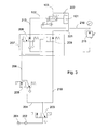
- a pneumatic control system comprising a multifunctional pneumatic valve 207 is installed on each fine adjustment firing valve 102.
- the compressed air feed source 201 is connected via a unidirectional valve 202 to a discharge valve 203, preferably represented by a conventional double-acting three-way solenoid valve.
- the discharge valve 203 is connected by a first conduit 204 to a firing activation valve 205, preferably represented by a conventional three-way solenoid valve with direct operation and spring return.
- the firing valve 205 is then connected, via the conduit 206, to operating devices of a multifunctional valve 207.
- the multifunctional valve 207 comprises a first release valve 208, preferably represented by a conventional three-way solenoid valve with direct operation and spring return, and a second release valve 209, preferably represented by a conventional two-way solenoid valve with direct operation and spring return.
- the firing valve 205 is connected to the operating devices of the first and second release valve of the multifunctional valve 207.
- the discharge valve 203 is connected via a feed conduit 210 directly to the second release valve 209, which is connected via the conduit 221 and a unidirectional valve 222 to a tubular element of the network 103.
- the valve 102 comprises a first connection to the conduit 213. This connection is the valve firing control. When this conduit 213 is put under atmospheric pressure via the valve 208, the valve 102 fires into the silo.
- the valve 102 comprises a second connection to a conduit 218.
- the conduit 210 supplies air at rated pressure to a pressure reducer 219 connected to the conduit 218.
- the pressure reducer 219 is set to the pressure at which the valve 102 terminates its discharge into the silo.
- the air in the conduit 218 is at the set pressure of the pressure reducer 219.
- it can be set to a pressure of 8 bar such as to discharge air into the silo only from the rated pressure of 10 bar until it reaches the pressure of 8 bar.
- a single pressure reducer 219 could be used for several valves, by connecting the conduit 218 to several valves 102.
- the valve 102 also comprises a third connection to a tubular element of the network 103.
- valve 102 In response to a firing command, the valve 102 connects the third connection to the silo, via a fourth connection.
- mechanical shutoff valves can be added between the multifunctional valve 207 and the valves 205 and 203.
- a first mechanical shutoff valve 214 is provided in the conduit 206 between the firing valve 205 and the operating devices of the multifunctional valve 207.
- a second mechanical shutoff valve 215 is provided in the feed conduit 210 downstream of the multifunctional valve.
- the first and second mechanical shutoff valve 214, 215 are operable simultaneously, they being preferably represented by conventional two-way solenoid valves with direct operation and spring return.
- a single digital pressure transmitter 220 is connected to the firing valve storage network 103, for example to a tubular element of the network 103, to control correct network operation.
- the system could operate with only the feed inlet 201, the firing valve 205 connected to the feed entry 201 and to the operating devices of the first release valve 208, itself connected to the firing valve 102; the feed entry 201 is also connected to the first release valve 208.
- the network must be initially filled with compressed air from the feed source 201.
- the discharge solenoid valve 203 is energized to connect the feed conduit 210 and hence the conduit 213 to the tubular element of the network 103, by way of the multifunctional valve 207 which is in communication with the feed source 201.
- the network 103 and its tubular elements are at rated operating pressure, typically at about 10 bar.
- the discharge solenoid valve 203 is energized. In this manner the tubular element of the network 103 is in contact with the atmosphere via the conduit 210.
- shutoff valves 214, 215 enable maintenance to be carried out on portions of the tubular network 103 of the invention while preventing loss of material contained in the silo.
- the firing solenoid valve 205 is energized, the air entering from the feed source 201 reaching the operating devices of the multifunctional valve 207 via the conduit 206. A vacuum is created in the conduit 213 which operates the firing valve.
- valves 102 When setting up the system, all the valves 102 are set such as to define the pressure at which the outflow of air to the silo 101 terminates. The firing times are also defined for each valve.
- a control unit not shown, handles these functions. Using a single pressure transmitter for the entire network, it becomes possible to continuously monitor the pressure variation within the network as a function of time. Said control unit can also monitor whether each valve fires at the required time and whether the set pressure is respected. This considerably simplifies system control.
- the firing valve 102 is controlled by the presence of vacuum in the conduit 213.
- the valve In a network in which the multifunctional valve 207is absent, the valve cannot be controlled from a distance of more than about ten metres from the valve, otherwise the vacuum (the command) is insufficient to operate the valve, or firing takes place with a delay and a duration not effective for the purpose.
- any separation, fracture or other accident to the control conduit 213 can lead to accidental firing, with the dangers which can derive therefrom.
- the conduit 213 is of negligible length and can be easily protected from external accidents.
- the conduit 213 can be advantageously formed by integrating it into the valve 102.
- the firing conduit formed with the solenoid valve 205 can then be positioned even at a considerable distance without pressure loss.
- the conduit 206 now becomes the firing command conduit, operating at rated feed pressure.
- the largest tubular elements are present at the valves of largest rated diameter.
- valves of 150 DN rated diameter tubular elements of diameter 150 are used.
- 150 x 10 1500 nl (normal litres) of air are used.
Landscapes
- Engineering & Computer Science (AREA)
- Mechanical Engineering (AREA)
- Filling Or Emptying Of Bunkers, Hoppers, And Tanks (AREA)
- Air Transport Of Granular Materials (AREA)
- Compounds Of Alkaline-Earth Elements, Aluminum Or Rare-Earth Metals (AREA)
- Apparatus For Disinfection Or Sterilisation (AREA)
- Food Preservation Except Freezing, Refrigeration, And Drying (AREA)
- Devices And Processes Conducted In The Presence Of Fluids And Solid Particles (AREA)
Claims (9)
- Aktivierungs- und Fluidisierungssystem (100), das mit einem Granulatsilo (101) oder -behälter verbunden ist und eine Vielzahl von Feineinstell-Strahlventilen (102) aufweist, die eine Einrichtung zur Begrenzung der Abgabe einer unter Druck stehenden luftförmigen Substanz von einem anfänglichen Druck bis zu einem vorbestimmten Enddruck haben, der geringer als der anfängliche Druck ist, und mit dem Silo (101) verbunden sind, dadurch gekennzeichnet, dass es ein röhrenförmiges Netzwerk (103) zur Speicherung der unter Druck stehenden luftförmigen Substanz bei dem anfänglichen Druck aufweist, mit dem die Vielzahl von Ventilen (102) unmittelbar verbunden sind, wodurch die Verwendung von Vorratsbehältern für die unter Druck stehende luftförmige Substanz in der Nähe der Vielzahl von Feineinstell-Strahlventilen (102) vermieden wird.
- System (100) nach Anspruch 1, dadurch gekennzeichnet, dass das röhrenförmige Netzwerk (103) zur Speicherung der unter Druck stehenden luftförmigen Substanz Verteilungsknoten (105) aufweist.
- System (100) nach Anspruch 1, dadurch gekennzeichnet, dass der röhrenförmige Speicher (103) so dimensioniert ist, dass eine maximale Kraft und ein maximaler Durchfluss an dem Einlass zu jedem Feineinstell-Strahlventil (102) sichergestellt wird, und dass bei dem röhrenförmigen Speichernetzwerk (103) die größten röhrenförmigen Elemente an den Ventilen des größten Nenndurchmessers vorhanden sind.
- System (100) nach Anspruch 1, dadurch gekennzeichnet, dass jedes Feineinstell-Strahlventil (102) einen Einspeiseeingang (201) für die unter Druck stehende luftförmige Substanz und ein Strahlventil (205) aufweist, das mit dem Einspeiseeingang (201) verbunden ist, wobei das Strahlventil (205) mit den Betriebsvorrichtungen eines ersten Freigabeventils (208) verbunden ist, wobei das erste Freigabeventil (208) mit dem Feineinstell-Strahlventil (102) verbunden ist, wobei der Einspeiseeingang (201) auch mit dem ersten Freigabeventil (208) verbunden ist, so dass dem Feineinstell-Strahlventil (102) dann, wenn es in seiner Ruhestellung ist, die unter Druck stehende luftförmige Substanz zugeführt wird, während das Feineinstell-Strahlventil (102) dann, wenn es in seiner Strahlstellung ist, mit der Atmosphäre verbunden ist.
- System (100) nach Anspruch 4, dadurch gekennzeichnet, dass jedes Feineinstell-Strahlventil (102) auch ein Abgabeventil (203) aufweist, das stromabwärts von dem Einspeiseeingang (201) angeordnet ist und von dem die Verbindungen zu dem Strahlventil (205) und zu dem ersten Freigabeventil (208) abzweigen, wobei das Abgabeventil (203) auch mit einem zweiten Freigabeventil (209) verbunden ist und wobei das Strahlventil (205) auch mit den Betriebsvorrichtungen des zweiten Freigabeventils (209) verbunden ist, wobei das zweite Freigabeventil (209) mit dem röhrenförmigen Netzwerk (103) verbunden ist.
- System (100) nach Anspruch 5, dadurch gekennzeichnet, dass die Vielzahl von Feineinstell-Strahlventilen (102) ferner zur Einstellung des vorbestimmten Enddrucks einen Druckminderer (219) aufweisen, der zwischen das Abgabeventil (103) und das Feineinstell-Strahlventil (102) verbunden ist.
- System (100) nach Anspruch 5, dadurch gekennzeichnet, dass jedes Feineinstell-Strahlventil (102) auch ein erstes mechanisches Absperrventil (214) aufweist, das zwischen dem Strahlventil (205) und dem ersten Freigabeventil (208) angeordnet ist, und ein zweites mechanisches Absperrventil (215), das zwischen dem Abgabeventil (203) und dem zweiten Freigabeventil (209) angeordnet ist.
- System (100) nach Anspruch 1, dadurch gekennzeichnet, dass es einen einzelnen digitalen Druckgeber (220) aufweist, der mit dem röhrenförmigen Speichernetzwerk (103) verbunden ist.
- System (100) nach Anspruch 1, dadurch gekennzeichnet, dass jedes der Vielzahl von Feineinstell-Strahlventilen (102) eine Einstelleinrichtung zum Einstellen des Wertes des vorbestimmten Enddrucks aufweist.
Applications Claiming Priority (1)
| Application Number | Priority Date | Filing Date | Title |
|---|---|---|---|
| IT000028A ITBG20080028A1 (it) | 2008-05-05 | 2008-05-05 | Sistema di attivazione e fluidificazione per silos o contenitori di materiali granulari. |
Publications (2)
| Publication Number | Publication Date |
|---|---|
| EP2116486A1 EP2116486A1 (de) | 2009-11-11 |
| EP2116486B1 true EP2116486B1 (de) | 2011-08-31 |
Family
ID=40302484
Family Applications (1)
| Application Number | Title | Priority Date | Filing Date |
|---|---|---|---|
| EP09005811A Active EP2116486B1 (de) | 2008-05-05 | 2009-04-27 | Aktivierungs- und Verflüssigungssystem verbunden an einem Silo oder Behälter für granulares Material |
Country Status (5)
| Country | Link |
|---|---|
| US (1) | US8152028B2 (de) |
| EP (1) | EP2116486B1 (de) |
| AT (1) | ATE522453T1 (de) |
| IT (1) | ITBG20080028A1 (de) |
| RU (1) | RU2500597C2 (de) |
Families Citing this family (2)
| Publication number | Priority date | Publication date | Assignee | Title |
|---|---|---|---|---|
| DE102014016871B4 (de) * | 2014-11-15 | 2016-06-02 | Khd Humboldt Wedag Gmbh | Verfahren zum Ausgleich des Gasdruckes in einem Massenflusstrichter und Massenflusstrichter |
| US10654646B1 (en) * | 2019-04-01 | 2020-05-19 | Suncue Company Ltd. | Containing apparatus for eliminating bridging |
Family Cites Families (14)
| Publication number | Priority date | Publication date | Assignee | Title |
|---|---|---|---|---|
| US2115023A (en) * | 1935-03-18 | 1938-04-26 | Reconstruction Finance Corp | Means for transporting material |
| US3671079A (en) * | 1970-04-16 | 1972-06-20 | Ma Tran Corp | Method and apparatus for handling material |
| SU785166A1 (ru) * | 1978-11-30 | 1980-12-07 | Кузнецкий Научно-Исследовательский Институт Строительства Угольных И Горнорудных Предприятий | Способ рыхлени сыпучих материалов в емкости |
| US4449644A (en) * | 1981-06-18 | 1984-05-22 | Ludlow Industries, Inc. | Blast aerator for fluidizing granular material |
| US4400131A (en) * | 1981-08-31 | 1983-08-23 | The Marmon Group, Inc. | Compressed air discharge system for trucks |
| US4826051A (en) * | 1983-10-24 | 1989-05-02 | Saul Milian | Manifold blaster |
| JPS60157424A (ja) * | 1984-01-25 | 1985-08-17 | Hitachi Ltd | 粉体付着防止用空気噴射装置 |
| US5106240A (en) * | 1988-06-21 | 1992-04-21 | Shell Oil Company | Aerated discharge device |
| DE4236896A1 (de) * | 1992-10-31 | 1994-05-05 | Maury Hans Dietmar | Luftkanone zur Beseitigung von Schüttgutanbackungen und -stauungen |
| DE19743789B4 (de) * | 1997-10-02 | 2005-10-06 | Agrichema Materialflusstechnik Gmbh & Co. Kg | Vorrichtung zum stoßartigen Ausblasen von Druckluft zur Beseitigung von Materialanbackungen von Schüttgütern in Reaktionsbehältern |
| DE10101041B4 (de) * | 2001-01-11 | 2014-09-18 | Agrilux Beteiligungs Gmbh | Ventileinheit für eine Vorrichtung zum stoßartigen Ausblasen von Druckluft aus einem Druckluftspeicherbehälter zur Beseitigung von Materialanbackungen und -aufstauungen |
| ITVR20050050A1 (it) * | 2005-05-02 | 2006-11-03 | Moretto Plastics Automation Srl | Dispositivo di fluidificazione per materiale granulare |
| ITMI20061406A1 (it) * | 2006-07-20 | 2008-01-21 | Larix Srl | Valvola di sparo a regolazione fine |
| DE202006016627U1 (de) * | 2006-10-30 | 2006-12-21 | Agrilux Beteiligungs Gmbh | System von Luftstoßgeräten |
-
2008
- 2008-05-05 IT IT000028A patent/ITBG20080028A1/it unknown
-
2009
- 2009-04-27 AT AT09005811T patent/ATE522453T1/de not_active IP Right Cessation
- 2009-04-27 EP EP09005811A patent/EP2116486B1/de active Active
- 2009-04-27 US US12/430,143 patent/US8152028B2/en not_active Expired - Fee Related
- 2009-05-04 RU RU2009117082/12A patent/RU2500597C2/ru active
Also Published As
| Publication number | Publication date |
|---|---|
| US8152028B2 (en) | 2012-04-10 |
| US20090272829A1 (en) | 2009-11-05 |
| EP2116486A1 (de) | 2009-11-11 |
| ATE522453T1 (de) | 2011-09-15 |
| RU2009117082A (ru) | 2010-11-10 |
| RU2500597C2 (ru) | 2013-12-10 |
| ITBG20080028A1 (it) | 2009-11-06 |
Similar Documents
| Publication | Publication Date | Title |
|---|---|---|
| US6749373B2 (en) | Installation for feeding a plurality of loads/cells of aluminum melting furnaces with bulk material such as aluminum oxide | |
| EP0402425B1 (de) | Vorrichtung und verfahren zur feinen dispersion von flüssigkeiten oder pulvern in einem gasförmigen medium | |
| US5407305A (en) | Continuous dense phase conveying method utilizing high pressure gas at predetermined gas pressures within a conveying pipe | |
| CN110356851A (zh) | 一种粉体发料装置和方法 | |
| US5855456A (en) | Apparatus and method for unblocking conveying pipe | |
| US8152028B2 (en) | Activation and fluidification system for granular material silos and containers | |
| KR20200107146A (ko) | 진공 컨베이어를 이용한 분체 자동 이송 시스템 | |
| US3437384A (en) | Conveying system and valve constructions therefor | |
| US3854778A (en) | Material handling plants | |
| CN210214114U (zh) | 一种自动稳压的气力输送系统 | |
| CN103785328A (zh) | 连续加料系统 | |
| KR100809864B1 (ko) | 소화병의 밸브 조립체 | |
| CA2098850C (en) | Loading system for particulate materials | |
| US6935813B2 (en) | Control mechanism, an installation and a method for transporting bulk material, granular material or powdery material through a conveyor line | |
| CN210943917U (zh) | 一种粉体发料装置 | |
| EP2044355B1 (de) | Fein einstellbares strahlventil | |
| CN102910453A (zh) | 膨胀珍珠岩输送器 | |
| KR101802818B1 (ko) | 원료이송 트랜스퍼 탱크 | |
| EP0117397B1 (de) | Verfahren dum Befüllen eines Gefässförderers | |
| CN209956639U (zh) | 一种用于沥青搅拌站的沙仓 | |
| US5353554A (en) | Injector dosing means | |
| SU1620390A1 (ru) | Установка дл сводообрушени материала в бункерах | |
| EP2273166B1 (de) | Fein einstellbares Strahlventil | |
| CA2007195C (en) | Process and apparatus for the fine dispersion of liquids or powders in a gaseous medium | |
| JP2001180792A (ja) | 高圧気体吐出装置 |
Legal Events
| Date | Code | Title | Description |
|---|---|---|---|
| PUAI | Public reference made under article 153(3) epc to a published international application that has entered the european phase |
Free format text: ORIGINAL CODE: 0009012 |
|
| AK | Designated contracting states |
Kind code of ref document: A1 Designated state(s): AT BE BG CH CY CZ DE DK EE ES FI FR GB GR HR HU IE IS IT LI LT LU LV MC MK MT NL NO PL PT RO SE SI SK TR |
|
| 17P | Request for examination filed |
Effective date: 20100416 |
|
| 17Q | First examination report despatched |
Effective date: 20100707 |
|
| GRAP | Despatch of communication of intention to grant a patent |
Free format text: ORIGINAL CODE: EPIDOSNIGR1 |
|
| RTI1 | Title (correction) |
Free format text: ACTIVATION AND FLUIDIFICATION SYSTEM CONNECTED TO A GRANULAR MATERIAL SILO OR CONTAINER |
|
| GRAS | Grant fee paid |
Free format text: ORIGINAL CODE: EPIDOSNIGR3 |
|
| GRAA | (expected) grant |
Free format text: ORIGINAL CODE: 0009210 |
|
| AK | Designated contracting states |
Kind code of ref document: B1 Designated state(s): AT BE BG CH CY CZ DE DK EE ES FI FR GB GR HR HU IE IS IT LI LT LU LV MC MK MT NL NO PL PT RO SE SI SK TR |
|
| REG | Reference to a national code |
Ref country code: GB Ref legal event code: FG4D Ref country code: CH Ref legal event code: EP |
|
| REG | Reference to a national code |
Ref country code: IE Ref legal event code: FG4D |
|
| REG | Reference to a national code |
Ref country code: DE Ref legal event code: R096 Ref document number: 602009002321 Country of ref document: DE Effective date: 20111201 |
|
| REG | Reference to a national code |
Ref country code: NL Ref legal event code: VDEP Effective date: 20110831 |
|
| LTIE | Lt: invalidation of european patent or patent extension |
Effective date: 20110831 |
|
| PG25 | Lapsed in a contracting state [announced via postgrant information from national office to epo] |
Ref country code: LT Free format text: LAPSE BECAUSE OF FAILURE TO SUBMIT A TRANSLATION OF THE DESCRIPTION OR TO PAY THE FEE WITHIN THE PRESCRIBED TIME-LIMIT Effective date: 20110831 Ref country code: FI Free format text: LAPSE BECAUSE OF FAILURE TO SUBMIT A TRANSLATION OF THE DESCRIPTION OR TO PAY THE FEE WITHIN THE PRESCRIBED TIME-LIMIT Effective date: 20110831 Ref country code: HR Free format text: LAPSE BECAUSE OF FAILURE TO SUBMIT A TRANSLATION OF THE DESCRIPTION OR TO PAY THE FEE WITHIN THE PRESCRIBED TIME-LIMIT Effective date: 20110831 Ref country code: SE Free format text: LAPSE BECAUSE OF FAILURE TO SUBMIT A TRANSLATION OF THE DESCRIPTION OR TO PAY THE FEE WITHIN THE PRESCRIBED TIME-LIMIT Effective date: 20110831 Ref country code: NL Free format text: LAPSE BECAUSE OF FAILURE TO SUBMIT A TRANSLATION OF THE DESCRIPTION OR TO PAY THE FEE WITHIN THE PRESCRIBED TIME-LIMIT Effective date: 20110831 Ref country code: NO Free format text: LAPSE BECAUSE OF FAILURE TO SUBMIT A TRANSLATION OF THE DESCRIPTION OR TO PAY THE FEE WITHIN THE PRESCRIBED TIME-LIMIT Effective date: 20111130 Ref country code: IS Free format text: LAPSE BECAUSE OF FAILURE TO SUBMIT A TRANSLATION OF THE DESCRIPTION OR TO PAY THE FEE WITHIN THE PRESCRIBED TIME-LIMIT Effective date: 20111231 |
|
| REG | Reference to a national code |
Ref country code: AT Ref legal event code: MK05 Ref document number: 522453 Country of ref document: AT Kind code of ref document: T Effective date: 20110831 |
|
| PG25 | Lapsed in a contracting state [announced via postgrant information from national office to epo] |
Ref country code: SI Free format text: LAPSE BECAUSE OF FAILURE TO SUBMIT A TRANSLATION OF THE DESCRIPTION OR TO PAY THE FEE WITHIN THE PRESCRIBED TIME-LIMIT Effective date: 20110831 Ref country code: CY Free format text: LAPSE BECAUSE OF FAILURE TO SUBMIT A TRANSLATION OF THE DESCRIPTION OR TO PAY THE FEE WITHIN THE PRESCRIBED TIME-LIMIT Effective date: 20110831 Ref country code: LV Free format text: LAPSE BECAUSE OF FAILURE TO SUBMIT A TRANSLATION OF THE DESCRIPTION OR TO PAY THE FEE WITHIN THE PRESCRIBED TIME-LIMIT Effective date: 20110831 Ref country code: AT Free format text: LAPSE BECAUSE OF FAILURE TO SUBMIT A TRANSLATION OF THE DESCRIPTION OR TO PAY THE FEE WITHIN THE PRESCRIBED TIME-LIMIT Effective date: 20110831 Ref country code: GR Free format text: LAPSE BECAUSE OF FAILURE TO SUBMIT A TRANSLATION OF THE DESCRIPTION OR TO PAY THE FEE WITHIN THE PRESCRIBED TIME-LIMIT Effective date: 20111201 |
|
| PG25 | Lapsed in a contracting state [announced via postgrant information from national office to epo] |
Ref country code: BE Free format text: LAPSE BECAUSE OF FAILURE TO SUBMIT A TRANSLATION OF THE DESCRIPTION OR TO PAY THE FEE WITHIN THE PRESCRIBED TIME-LIMIT Effective date: 20110831 |
|
| PG25 | Lapsed in a contracting state [announced via postgrant information from national office to epo] |
Ref country code: CZ Free format text: LAPSE BECAUSE OF FAILURE TO SUBMIT A TRANSLATION OF THE DESCRIPTION OR TO PAY THE FEE WITHIN THE PRESCRIBED TIME-LIMIT Effective date: 20110831 Ref country code: SK Free format text: LAPSE BECAUSE OF FAILURE TO SUBMIT A TRANSLATION OF THE DESCRIPTION OR TO PAY THE FEE WITHIN THE PRESCRIBED TIME-LIMIT Effective date: 20110831 |
|
| PG25 | Lapsed in a contracting state [announced via postgrant information from national office to epo] |
Ref country code: EE Free format text: LAPSE BECAUSE OF FAILURE TO SUBMIT A TRANSLATION OF THE DESCRIPTION OR TO PAY THE FEE WITHIN THE PRESCRIBED TIME-LIMIT Effective date: 20110831 Ref country code: RO Free format text: LAPSE BECAUSE OF FAILURE TO SUBMIT A TRANSLATION OF THE DESCRIPTION OR TO PAY THE FEE WITHIN THE PRESCRIBED TIME-LIMIT Effective date: 20110831 Ref country code: PT Free format text: LAPSE BECAUSE OF FAILURE TO SUBMIT A TRANSLATION OF THE DESCRIPTION OR TO PAY THE FEE WITHIN THE PRESCRIBED TIME-LIMIT Effective date: 20120102 Ref country code: PL Free format text: LAPSE BECAUSE OF FAILURE TO SUBMIT A TRANSLATION OF THE DESCRIPTION OR TO PAY THE FEE WITHIN THE PRESCRIBED TIME-LIMIT Effective date: 20110831 |
|
| PG25 | Lapsed in a contracting state [announced via postgrant information from national office to epo] |
Ref country code: DK Free format text: LAPSE BECAUSE OF FAILURE TO SUBMIT A TRANSLATION OF THE DESCRIPTION OR TO PAY THE FEE WITHIN THE PRESCRIBED TIME-LIMIT Effective date: 20110831 |
|
| PLBE | No opposition filed within time limit |
Free format text: ORIGINAL CODE: 0009261 |
|
| STAA | Information on the status of an ep patent application or granted ep patent |
Free format text: STATUS: NO OPPOSITION FILED WITHIN TIME LIMIT |
|
| 26N | No opposition filed |
Effective date: 20120601 |
|
| REG | Reference to a national code |
Ref country code: DE Ref legal event code: R097 Ref document number: 602009002321 Country of ref document: DE Effective date: 20120601 |
|
| PG25 | Lapsed in a contracting state [announced via postgrant information from national office to epo] |
Ref country code: MC Free format text: LAPSE BECAUSE OF NON-PAYMENT OF DUE FEES Effective date: 20120430 |
|
| PG25 | Lapsed in a contracting state [announced via postgrant information from national office to epo] |
Ref country code: MK Free format text: LAPSE BECAUSE OF FAILURE TO SUBMIT A TRANSLATION OF THE DESCRIPTION OR TO PAY THE FEE WITHIN THE PRESCRIBED TIME-LIMIT Effective date: 20110831 |
|
| PG25 | Lapsed in a contracting state [announced via postgrant information from national office to epo] |
Ref country code: IE Free format text: LAPSE BECAUSE OF NON-PAYMENT OF DUE FEES Effective date: 20120427 Ref country code: ES Free format text: LAPSE BECAUSE OF FAILURE TO SUBMIT A TRANSLATION OF THE DESCRIPTION OR TO PAY THE FEE WITHIN THE PRESCRIBED TIME-LIMIT Effective date: 20111211 |
|
| PG25 | Lapsed in a contracting state [announced via postgrant information from national office to epo] |
Ref country code: BG Free format text: LAPSE BECAUSE OF FAILURE TO SUBMIT A TRANSLATION OF THE DESCRIPTION OR TO PAY THE FEE WITHIN THE PRESCRIBED TIME-LIMIT Effective date: 20111130 |
|
| PG25 | Lapsed in a contracting state [announced via postgrant information from national office to epo] |
Ref country code: MT Free format text: LAPSE BECAUSE OF FAILURE TO SUBMIT A TRANSLATION OF THE DESCRIPTION OR TO PAY THE FEE WITHIN THE PRESCRIBED TIME-LIMIT Effective date: 20110831 |
|
| REG | Reference to a national code |
Ref country code: CH Ref legal event code: PL |
|
| PG25 | Lapsed in a contracting state [announced via postgrant information from national office to epo] |
Ref country code: LI Free format text: LAPSE BECAUSE OF NON-PAYMENT OF DUE FEES Effective date: 20130430 Ref country code: CH Free format text: LAPSE BECAUSE OF NON-PAYMENT OF DUE FEES Effective date: 20130430 |
|
| PG25 | Lapsed in a contracting state [announced via postgrant information from national office to epo] |
Ref country code: LU Free format text: LAPSE BECAUSE OF NON-PAYMENT OF DUE FEES Effective date: 20120427 |
|
| PG25 | Lapsed in a contracting state [announced via postgrant information from national office to epo] |
Ref country code: HU Free format text: LAPSE BECAUSE OF FAILURE TO SUBMIT A TRANSLATION OF THE DESCRIPTION OR TO PAY THE FEE WITHIN THE PRESCRIBED TIME-LIMIT Effective date: 20090427 |
|
| REG | Reference to a national code |
Ref country code: FR Ref legal event code: PLFP Year of fee payment: 8 |
|
| PGFP | Annual fee paid to national office [announced via postgrant information from national office to epo] |
Ref country code: GB Payment date: 20160331 Year of fee payment: 8 |
|
| PGFP | Annual fee paid to national office [announced via postgrant information from national office to epo] |
Ref country code: TR Payment date: 20160408 Year of fee payment: 8 |
|
| REG | Reference to a national code |
Ref country code: FR Ref legal event code: PLFP Year of fee payment: 9 |
|
| GBPC | Gb: european patent ceased through non-payment of renewal fee |
Effective date: 20170427 |
|
| PG25 | Lapsed in a contracting state [announced via postgrant information from national office to epo] |
Ref country code: GB Free format text: LAPSE BECAUSE OF NON-PAYMENT OF DUE FEES Effective date: 20170427 |
|
| REG | Reference to a national code |
Ref country code: FR Ref legal event code: PLFP Year of fee payment: 10 |
|
| PG25 | Lapsed in a contracting state [announced via postgrant information from national office to epo] |
Ref country code: TR Free format text: LAPSE BECAUSE OF NON-PAYMENT OF DUE FEES Effective date: 20170427 |
|
| P01 | Opt-out of the competence of the unified patent court (upc) registered |
Effective date: 20230602 |
|
| PGFP | Annual fee paid to national office [announced via postgrant information from national office to epo] |
Ref country code: IT Payment date: 20250320 Year of fee payment: 17 |
|
| PGFP | Annual fee paid to national office [announced via postgrant information from national office to epo] |
Ref country code: DE Payment date: 20250417 Year of fee payment: 17 |
|
| PGFP | Annual fee paid to national office [announced via postgrant information from national office to epo] |
Ref country code: FR Payment date: 20250425 Year of fee payment: 17 |