EP2116463B1 - Parkvorrichtung für Fahrräder - Google Patents
Parkvorrichtung für Fahrräder Download PDFInfo
- Publication number
- EP2116463B1 EP2116463B1 EP09006298A EP09006298A EP2116463B1 EP 2116463 B1 EP2116463 B1 EP 2116463B1 EP 09006298 A EP09006298 A EP 09006298A EP 09006298 A EP09006298 A EP 09006298A EP 2116463 B1 EP2116463 B1 EP 2116463B1
- Authority
- EP
- European Patent Office
- Prior art keywords
- guide
- bicycle
- around
- lever
- operating lever
- Prior art date
- Legal status (The legal status is an assumption and is not a legal conclusion. Google has not performed a legal analysis and makes no representation as to the accuracy of the status listed.)
- Not-in-force
Links
Images


Classifications
-
- B—PERFORMING OPERATIONS; TRANSPORTING
- B62—LAND VEHICLES FOR TRAVELLING OTHERWISE THAN ON RAILS
- B62H—CYCLE STANDS; SUPPORTS OR HOLDERS FOR PARKING OR STORING CYCLES; APPLIANCES PREVENTING OR INDICATING UNAUTHORIZED USE OR THEFT OF CYCLES; LOCKS INTEGRAL WITH CYCLES; DEVICES FOR LEARNING TO RIDE CYCLES
- B62H3/00—Separate supports or holders for parking or storing cycles
- B62H3/12—Hanging-up devices
Definitions
- the invention relates to a parking device for bicycles comprising an elongated guide supported at a distance above the ground below a ceiling and guiding a first runner freely movable along the length of said guide which supports a suspending hook to be hooked around a part of a bicycle at a first position thereof.
- Such a device is known as such from the German Gebrauchsmuster DE 90 12 517 U1 , which is considered as the closest prior art.
- the guide lies at a distance above the ground which is only slightly greater than the height of a bicycle arid for parking a bicycle the single runner with its hook is positioned at the freely accessible end of the straight guide and is then hooked around the steering handles meanwhile pulling the bicycle upwardly somewhat to raise the front wheel thereof free from the ground. The bicycle is then pushed forwardly until it is completely below the ceiling.
- the invention aims to obviate these drawbacks and to provide a parking device for bicycles of the kind as described above with a simple structure which is furthermore very insensitive for hooliganism because the parked bicycles are raised high above the ground.
- this support is constituted by an elongated guide for two runners movable along this guide which each cany the second end of a pulling element, said guide comprising a first, essentially straight, end part which is pivotally supported at its first end at a distance above the ground around a horizontal pivot axis, continuing via an obtuse angle into a downwardly directed middle part which continues via an obtuse angle in an upwardly directed second end part, said guide being controllably rotatable around this pivot axis from a stable, low position, in which a bicycle can be suspended from the hooks hanging thereunder into a stable high position in which the hooks supporting the bicycle lie under the first end part of the guide.
- a very user-friendly embodiment of the invention which comprises an operating mechanism for swinging the guide from the low position thereof into the high position, and opposite, comprising a pulling element which is connected with its first end to the middle part of the guide and is anchored with its second end at a distance above this middle part and which is, starting from the connection thereof with the guide, firstly slung around a fixed guiding roller above this anchoring point, thereafter runs in the direction of the second end of the guide and is, above this second end of the elongated guide, slung around a second roller coupled to the first end of an operating lever which is rotatably supported at a distance below this fixed guide roller.
- the use of the bicycle parking device is simplified when the operating lever is provided with a locking device for locking this lever in the respective end positions thereof.
- the force which must be exerted by the user on the bicycle parking device is diminished still further by using a force accumulator which acts upon the first end of the operating lever in the direction of the second end of the guide.
- a force accumulator which acts upon the first end of the operating lever in the direction of the second end of the guide.
- This can be for instance a counterweight but is preferably a gas spring.
- DE 103 06 596 describes a device for parking bicycles which comprises an elongated guide for a single runner with a suspending hook to be hooked around the steering handle and having a very specific structure : this guide is made up from an number of successive hollow segments which each houses two halves of a leaf spring such that these springs have the tendancy to line up the segments into a straight line.
- This known device has thus a very complicated and costly structure and cannot raise the bicycle into an elevated position.
- US 6 691 878 B1 describes a system for elevating and lowering a load, particularly a bicycle, comprising a complicated set-up of pivotally interconnected spring-loaded arms.
- US 6 302 278 describes a bicycle display rack, also comprising a number of pivotally interconnected links co-operating with a cylinder and piston combination for raising and lowering a bicycle.
- JP 55 087672 A shows a bicycle parking device in which bicycles can be parked at two different levels, one above the other, by means of a pivoting straight lifting lever.
- US 2005/0098511 A1 describes a utility hook carrier, suitable for supporting a bicycle and destined for co-operation with a standard overhead garage door track.
- RU 2049710 C1 describes a complicated bicycle parking device with two parallel guides, each guiding a vertical lifting rod of which the respective ends are connected to a clamp which holds a bicycle, such that it can be brought from a horizontal position into a vertical storage position.
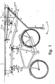
- Fig. 1 shows a supporting profile 2, supported by a ceiling of a suitable structure, having a first downwardly directed carrying bracket 4 which supports in the pivot axis 6 the and 8 of a elongated guide which is indicated in its entirety with reference numeral 10.
- This guide consists of a U-profile which is open at its under side and of which both legs continue in oppositely directed end flanges 12.
- This guide comprises, as the drawing shows, a first, essentially straight, end part 10a, which merges into a middle part 10b which runs, starting from the part 10a, downwardly, and thereafter finally a second end part 10c which runs upwardly again.
- this elongated guide there are two movable runners 14a, 14b each with two pairs of rollers 16a, 16b, 16c, 16d which bear upon the end flanges 12.
- Each runner has a downwardly directed lug 18a and 18b respectively which goes through the space present between the end edges of the flanges. 12 and which each support a suspending hook 20a and 20b respectively.
- hooks are destined to be hooked aground a bicycle 22 which is to be parked and to this end the front hook 20a can be hooked around the steering handle 24 while the other .hook 20b can be hooked around the saddle 26 This way of hooking up a bicycle is known as such.
- the ceiling or the celling structure 2 supports, near to the middle part 10b of the guide. 10 a second downwardly directed bracket 30 and, above the end part 10c, a third downwardly directed bracket 32.
- the second bracket 30 is provided near the lower end thereof with a guide roller or gear wheel 34 to cooperate with a supple pulling element 36, here shown to be a chain.
- the third bracket 32 supports in a pivot point (30) the endpart 40 of an operating lever 42 of which the second part 44 includes with the part 40 thereof an obtuse angle.
- a second gear wheel 46 is rotatingly supported at the upper end of the end part 40 and the chain 36 is guided around it.
- the chain 36 is thus with its first end 48 fixed to the middle part 10b near to the place where this middle part merges into the second end part 10c, then guided over the gear wheel 34, thereafter over the gear wheel 46 and then runs back to a fixing point 50 on the ceiling Structure 2.
- This fixing point 50 lies above the middle part 10b of the elongated guide 10.
- a linear force accumulator which acts between the guiding roller 46 and the end 52 and is here shown to be a gas spring 57, 59 of which the cylinder 57 is coupled to the guiding roller 46 and of which the piston rod 59 is coupled to the end 52 of the fourth bracket 54.
- Swinging the end 44a of the operating lever part 44 in the direction of the arrow 56 has as a result that the gear wheel 46 moves to the left in the plane of drawing, so that the end 48 of the chain moves downwardly and the elongated guide 10 swings to the right around the pivot axis 6 so that the bicycle 22 moves downwardly and the gas spring 57, 59 is compressed; swinging the end 44a in the direction of the arrow 58 has as a result that the guiding roller 46 rotates to the right, and an upwardly directed force is exerted on the connection point of first end 48 on the middle part 10b of the guide so that the bicycle is lifted, this movement being supported by the action of the expanding gas spring. In this way the lifting-up of the bicycle is made easier.
- the operating lever 42 is preferably provided with a locking mechanism to lock this lever in two positions.
- FIG. 2 shows schematically an auxiliary device for aiding the initial movement of a bicycle along the guide 10.
- the principle of this device is known in itself and it is structured as follows it comprises a second lever 33 which is at its lower end 35 provided with a suitable gripper 37 ( shown schematically) which can grip around the second runner 14b.
- This second lever 33 has a cranked endpart 39 and two straight parts 33a,33b pivotally interconnected at 51 and co-operating with a hairpinspring with the legs 53a,53b. This hairpinspring tries to keep the parts 33a,33b aligned.
- the endpart 39 is pivotally supported at the pivot point 41 by the bracket 41a which depends from the bracket 32 and this pivot point lies dose below the pivot point 38 of the lever 42.
- the levers 42 and 39 are intercoupled by a short coupling lever 43a which pivotally coupled with the leverpart 39 at the pivot point 45a and is pivotally coupled with the lever 42 at the pivot point 47b which is present at the end of the bracket 47a, carried by the lever 42.
- the set-up is such that, when the lever 42 rotates around the pivot point 38 over a certain angle a the endpart 39 of the lever 33 rotates around its pivot point 41 over the angle slightly smaller than 2 a . More precisely in the shown embodiment a rotation of 90 degrees of the lever 42 brings about a rotation of 160 degrees of the lever 33.
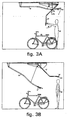
- the starting position is shown in fig. 3A ; the operating lever 42 is in its final position to the left, the gas spring 57, 59 is completely extended, the guide 10 is in its uppermost position and both the runners 14a, 14b lie at the end of the second end part 10c of the guide 10; they can be intercoinnected in this position by means of the hook 20b.
- the user 60 grips the operating lever 42 at the end 44a thereof and rotates it in the direction of the arrow 56 ( fig. 3A ), thus to the left and upwardly, until the situation as shown in fig. 3B is reached.
- the gas spring is now compressed and the operating lever 42 is locked in the locking opening 47.
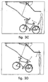
- the user now hooks, as fig. 3C shows, firstly the hook 20a to the steering handle 24 and thereafter the hook 20b behind the saddle 26 - meaning that he must lift the bicycle somewhat- until the situation of fig 3D is reached. Then the user presses the operating lever 42 until it is in the position shown in fig. 3E in which the locking pin (40a) is locked in the locking opening 43; the bicycle is now nearly horizontal.
- Pushing the end 44a further to the left results in a lifting of the guide 10, supported by the gas spring, into the second stable end position, and during this movement the runners 14a, 14b with the bicycle hanging thereon move from right to left in the drawing ( possibly aided by a further pushing force exerted by the auxiliary device) until they assume the second stable end position shown in fig. 3F .
- the user can, if necessary, provide a ring or cable lock 62 around the rear wheel 64 of this bicycle and the operating lever part 44.
Landscapes
- Engineering & Computer Science (AREA)
- Mechanical Engineering (AREA)
- Steering Devices For Bicycles And Motorcycles (AREA)
- Regulating Braking Force (AREA)
- Power Steering Mechanism (AREA)
- Steering Control In Accordance With Driving Conditions (AREA)
- Handcart (AREA)
Claims (8)
- Parkvorrichtung für Fahrräder mit einer länglichen Führung (10), die in einem Abstand über dem Boden gehalten ist und einen ersten Läufer (14a) frei beweglich entlang der Länge der Führung (10) führt, welcher erste Läufer (14a) einen ersten Aufhängehaken (20a) trägt, in den ein erster Teil (24) eines zu parkenden Fahrrads (22) in einer ersten Position desselben einzuhängen ist, dadurch gekennzeichnet, dass die Führung (10) einen zweiten derartigen Läufer (14b) trägt, welcher einen zweiten Aufhängehaken (20b) trägt, in den ein zweiter Teil (26) des Fahrrads (22) in einem Abstand vom ersten Teil (24) einzuhängen ist, wobei die Führung (10) einen ersten, im Wesentlichen geraden Endteil (10a) aufweist, der an seinem freien Ende in einem Abstand über dem Boden schwenkbar um eine horizontale Schwenkachse (6) gehalten ist und sich über einen stumpfen Winkel in einem nach unten gerichteten Mittelteil (10b) fortsetzt, welcher sich über einen stumpfen Winkel in einem nach oben gerichteten, zweiten Endteil (10c) fortsetzt, wobei die Führung (10) um diese Schwenkachse (6) aus einer stabilen niedrigen Position, in welcher ein Fahrrad (22) in den Haken (20a, 20b) eingehängt werden kann und unter diesen hängt, in eine stabile hohe Position, in welcher die das Fahrrad (22) tragenden Haken (20a, 20b) unter dem ersten Endteil (10a) der Führung (10) liegen, kontrolliert verdreht werden kann.
- Vorrichtung nach Anspruch 1 mit einem Betätigungsmechanismus zum Verschwenken der Führung (10) aus ihrer niedrigen Position in die hohe Position und umgekehrt, welcher ein Zugelement (36) aufweist, das mit seinem ersten Ende (48) an einer ersten Befestigungsstelle am Mittelteil (10b) der Führung (10) angebracht und mit seinem zweiten Ende (50a) an einer zweiten Befestigungsstelle (50) an einer Deckenkonstruktion (2) in einem Abstand über dem Mittelteil (10b) befestigt ist, und welches, beginnend von seiner ersten Befestigungsstelle am Mittelteil (10b) der Führung (10), zuerst um eine fixe Führungsrolle (34) oberhalb der ersten Befestigungsstelle geschlungen ist, dann in Richtung des zweiten Endes der Führung (10) läuft, wie in der hohen Position derselben zu sehen ist, und über dem zweiten Ende der länglichen Führung (10) um eine zweite Rolle (46) geschlungen ist, die mit dem ersten Ende eines Betätigungshebels (42) gekuppelt ist, welcher in einem ersten Schwenkpunkt (38) in einem Abstand unterhalb der fixen Führungsrolle (34) drehbar gehalten ist.
- Vorrichtung nach Anspruch 2, wobei der Betätigungshebel (42) mit einem Verriegelungsmechanismus (40a, 43, 47) zur Verriegelung dieses Betätigungshebels (42) in jeweiligen Endpositionen desselben versehen ist.
- Vorrichtung nach Anspruch 2 oder 3 mit einem Kraftspeicher (57, 59), der auf das erste Ende des Betätigungshebels (42) in Richtung des zweiten Endes der Führung (10) wirkt, gesehen in der hohen Position derselben.
- Vorrichtung nach Anspruch 4, wobei der Kraftspeicher (57, 59) eine Gasfeder ist.
- Vorrichtung nach einem der Ansprüche 2 bis 4, mit einem länglichen Schubhebel (33), der an seinem ersten, gekröpften Ende (39) schwenkbar gehalten ist, in einem zweiten Schwenkpunkt (41) welcher nahe dem ersten Schwenkpunkt (38) des Betätigungshebels (42) liegt, und welcher Schubhebel (33) über einen kurzen Kupplungshebel (47a) schwenkbar mit einem Kupplungspunkt (47b) am Betätigungshebel (42) gekuppelt ist und mit dem zweiten Ende (35) auf den zweiten Läufer (14b) wirken kann.
- Vorrichtung nach einem der Ansprüche 1 bis 6, dadurch gekennzeichnet, dass die Führung (10) ein nach unten offenen U-Profil aufweist, dessen Schenkel sich in entgegengesetzt gerichteten Endflanschen fortsetzen, auf welchen die Läufer (14a, 14b) gelagert sind.
- Vorrichtung nach Anspruch 7, dadurch gekennzeichnet, dass die Läufer (14a, 14b) jeweils eine Gruppe von Rollen (16a, 16b, 16c, 16d) aufweisen.
Applications Claiming Priority (1)
| Application Number | Priority Date | Filing Date | Title |
|---|---|---|---|
| NL1035402A NL1035402C2 (nl) | 2008-05-08 | 2008-05-08 | Fietsenlift. |
Publications (2)
| Publication Number | Publication Date |
|---|---|
| EP2116463A1 EP2116463A1 (de) | 2009-11-11 |
| EP2116463B1 true EP2116463B1 (de) | 2010-08-18 |
Family
ID=40085547
Family Applications (1)
| Application Number | Title | Priority Date | Filing Date |
|---|---|---|---|
| EP09006298A Not-in-force EP2116463B1 (de) | 2008-05-08 | 2009-05-08 | Parkvorrichtung für Fahrräder |
Country Status (4)
| Country | Link |
|---|---|
| EP (1) | EP2116463B1 (de) |
| AT (1) | ATE477993T1 (de) |
| DE (1) | DE602009000118D1 (de) |
| NL (1) | NL1035402C2 (de) |
Families Citing this family (2)
| Publication number | Priority date | Publication date | Assignee | Title |
|---|---|---|---|---|
| DE102014010328B4 (de) * | 2014-07-14 | 2020-06-18 | Hans-Jürgen Deuerer | Einrichtung zur Aufbewahrung von Gegenständen, insbesondere Fahrrädern unter einer Gebäudedecke |
| CN108189934A (zh) * | 2017-12-30 | 2018-06-22 | 广东技术师范学院 | 一种自行车停放装置 |
Family Cites Families (14)
| Publication number | Priority date | Publication date | Assignee | Title |
|---|---|---|---|---|
| US624231A (en) * | 1899-05-02 | Bicycle-rack | ||
| GB764387A (en) * | 1955-02-28 | 1956-12-28 | Paul Wirz | Improvements in and relating to parking devices for bicycles and the like |
| JPS5587672A (en) * | 1978-12-23 | 1980-07-02 | Kato Hitoshi | Tridimensional custody equipment for bicycle or like |
| JPH0356596Y2 (de) * | 1987-12-15 | 1991-12-19 | ||
| DE9012517U1 (de) * | 1990-08-31 | 1992-01-02 | Immler, Josef, 8039 Puchheim | Aufbewahrungsvorrichtung für Fahrräder |
| WO1994005467A1 (en) * | 1992-09-08 | 1994-03-17 | John Winston Childs | Improvements in and relating to lifting apparatus |
| RU2049710C1 (ru) * | 1992-12-14 | 1995-12-10 | Научно-исследовательский технологический институт "Прогресс" | Устройство для сборки и транспортирования изделий |
| DE19624057A1 (de) * | 1996-06-17 | 1997-12-18 | Karl Kemper | Fahrrad-Elevator |
| US6095344A (en) * | 1998-01-07 | 2000-08-01 | White; Kenneth D. | Overhead storage system |
| US6302278B1 (en) * | 2000-06-22 | 2001-10-16 | Raymond Dueck | Bicycle display rack |
| DE10306596A1 (de) * | 2002-02-20 | 2003-08-28 | Josef Immler | Vorrichtung zur Aufnahme wenigstens eines Fahrrades |
| US6691878B1 (en) * | 2002-08-08 | 2004-02-17 | Ernest G. Ouitz | Arm and brace system |
| US7000783B2 (en) * | 2003-11-07 | 2006-02-21 | Webb Martin D | Utility hook for attachment to an overhead garage door track |
| ITMI20051034A1 (it) * | 2005-06-03 | 2006-12-04 | Gianfranco Pricoli | Dispositivo perfezionato per ricoverare biciclette e simili |
-
2008
- 2008-05-08 NL NL1035402A patent/NL1035402C2/nl not_active IP Right Cessation
-
2009
- 2009-05-08 AT AT09006298T patent/ATE477993T1/de not_active IP Right Cessation
- 2009-05-08 EP EP09006298A patent/EP2116463B1/de not_active Not-in-force
- 2009-05-08 DE DE602009000118T patent/DE602009000118D1/de active Active
Also Published As
| Publication number | Publication date |
|---|---|
| EP2116463A1 (de) | 2009-11-11 |
| DE602009000118D1 (de) | 2010-09-30 |
| ATE477993T1 (de) | 2010-09-15 |
| NL1035402C2 (nl) | 2009-11-11 |
Similar Documents
| Publication | Publication Date | Title |
|---|---|---|
| US5474189A (en) | Bicycle lift and storage system | |
| US6406248B1 (en) | Apparatus for lifting and moving an upright cylindrical container | |
| EP2402530B1 (de) | Bewegliche Basis mit Steuerfläche | |
| EP0179712B1 (de) | Fahrbare Tragbahre mit einer höhenverstellbaren Liegefläche | |
| KR100998713B1 (ko) | 자전거 주차대 | |
| US20160257535A1 (en) | Sport Utility Vehicle Mobile Hard Top Removal, Store, and Install Device | |
| EP2116463B1 (de) | Parkvorrichtung für Fahrräder | |
| US7997846B2 (en) | Drywall panel lifter | |
| JP5600046B2 (ja) | 二段式駐輪装置 | |
| JP5888638B2 (ja) | 二段式駐輪装置 | |
| KR20110082363A (ko) | 시스템 동바리 설치 리프트 | |
| KR101645804B1 (ko) | 승강구동식 자전거 거치장치 | |
| KR200428701Y1 (ko) | 옷걸이용 행거 | |
| KR20110073078A (ko) | 자전거 보관대 | |
| EP2447136A1 (de) | Fahrradabstellsystem | |
| JPH0337348Y2 (de) | ||
| JP2008254605A (ja) | 駐輪装置 | |
| JPH06199256A (ja) | 二段式駐輪装置 | |
| DE102009053165B3 (de) | Fahrradaufhängung für eine Fahrradaufbewahrungsbox | |
| TWI473735B (zh) | An elevated bicycle frame | |
| NL1011598C2 (nl) | Inrichting voor het stallen van rijwielen. | |
| RU189480U1 (ru) | Держатель запасного колеса транспортного средства | |
| JP6219289B2 (ja) | 駐輪装置 | |
| KR20110019005A (ko) | 자전거 보관대 | |
| CN223336641U (zh) | 逃生装置 |
Legal Events
| Date | Code | Title | Description |
|---|---|---|---|
| PUAI | Public reference made under article 153(3) epc to a published international application that has entered the european phase |
Free format text: ORIGINAL CODE: 0009012 |
|
| 17P | Request for examination filed |
Effective date: 20090508 |
|
| AK | Designated contracting states |
Kind code of ref document: A1 Designated state(s): AT BE BG CH CY CZ DE DK EE ES FI FR GB GR HR HU IE IS IT LI LT LU LV MC MK MT NL NO PL PT RO SE SI SK TR |
|
| GRAP | Despatch of communication of intention to grant a patent |
Free format text: ORIGINAL CODE: EPIDOSNIGR1 |
|
| GRAS | Grant fee paid |
Free format text: ORIGINAL CODE: EPIDOSNIGR3 |
|
| GRAA | (expected) grant |
Free format text: ORIGINAL CODE: 0009210 |
|
| AK | Designated contracting states |
Kind code of ref document: B1 Designated state(s): AT BE BG CH CY CZ DE DK EE ES FI FR GB GR HR HU IE IS IT LI LT LU LV MC MK MT NL NO PL PT RO SE SI SK TR |
|
| REG | Reference to a national code |
Ref country code: GB Ref legal event code: FG4D |
|
| REG | Reference to a national code |
Ref country code: CH Ref legal event code: EP |
|
| REG | Reference to a national code |
Ref country code: IE Ref legal event code: FG4D |
|
| REF | Corresponds to: |
Ref document number: 602009000118 Country of ref document: DE Date of ref document: 20100930 Kind code of ref document: P |
|
| REG | Reference to a national code |
Ref country code: NL Ref legal event code: T3 |
|
| LTIE | Lt: invalidation of european patent or patent extension |
Effective date: 20100818 |
|
| PG25 | Lapsed in a contracting state [announced via postgrant information from national office to epo] |
Ref country code: NO Free format text: LAPSE BECAUSE OF FAILURE TO SUBMIT A TRANSLATION OF THE DESCRIPTION OR TO PAY THE FEE WITHIN THE PRESCRIBED TIME-LIMIT Effective date: 20101118 Ref country code: LT Free format text: LAPSE BECAUSE OF FAILURE TO SUBMIT A TRANSLATION OF THE DESCRIPTION OR TO PAY THE FEE WITHIN THE PRESCRIBED TIME-LIMIT Effective date: 20100818 Ref country code: FI Free format text: LAPSE BECAUSE OF FAILURE TO SUBMIT A TRANSLATION OF THE DESCRIPTION OR TO PAY THE FEE WITHIN THE PRESCRIBED TIME-LIMIT Effective date: 20100818 Ref country code: AT Free format text: LAPSE BECAUSE OF FAILURE TO SUBMIT A TRANSLATION OF THE DESCRIPTION OR TO PAY THE FEE WITHIN THE PRESCRIBED TIME-LIMIT Effective date: 20100818 |
|
| PG25 | Lapsed in a contracting state [announced via postgrant information from national office to epo] |
Ref country code: SI Free format text: LAPSE BECAUSE OF FAILURE TO SUBMIT A TRANSLATION OF THE DESCRIPTION OR TO PAY THE FEE WITHIN THE PRESCRIBED TIME-LIMIT Effective date: 20100818 Ref country code: PL Free format text: LAPSE BECAUSE OF FAILURE TO SUBMIT A TRANSLATION OF THE DESCRIPTION OR TO PAY THE FEE WITHIN THE PRESCRIBED TIME-LIMIT Effective date: 20100818 Ref country code: IS Free format text: LAPSE BECAUSE OF FAILURE TO SUBMIT A TRANSLATION OF THE DESCRIPTION OR TO PAY THE FEE WITHIN THE PRESCRIBED TIME-LIMIT Effective date: 20101218 Ref country code: HR Free format text: LAPSE BECAUSE OF FAILURE TO SUBMIT A TRANSLATION OF THE DESCRIPTION OR TO PAY THE FEE WITHIN THE PRESCRIBED TIME-LIMIT Effective date: 20100818 Ref country code: BG Free format text: LAPSE BECAUSE OF FAILURE TO SUBMIT A TRANSLATION OF THE DESCRIPTION OR TO PAY THE FEE WITHIN THE PRESCRIBED TIME-LIMIT Effective date: 20101118 Ref country code: CY Free format text: LAPSE BECAUSE OF FAILURE TO SUBMIT A TRANSLATION OF THE DESCRIPTION OR TO PAY THE FEE WITHIN THE PRESCRIBED TIME-LIMIT Effective date: 20100818 |
|
| PG25 | Lapsed in a contracting state [announced via postgrant information from national office to epo] |
Ref country code: LV Free format text: LAPSE BECAUSE OF FAILURE TO SUBMIT A TRANSLATION OF THE DESCRIPTION OR TO PAY THE FEE WITHIN THE PRESCRIBED TIME-LIMIT Effective date: 20100818 Ref country code: SE Free format text: LAPSE BECAUSE OF FAILURE TO SUBMIT A TRANSLATION OF THE DESCRIPTION OR TO PAY THE FEE WITHIN THE PRESCRIBED TIME-LIMIT Effective date: 20100818 Ref country code: GR Free format text: LAPSE BECAUSE OF FAILURE TO SUBMIT A TRANSLATION OF THE DESCRIPTION OR TO PAY THE FEE WITHIN THE PRESCRIBED TIME-LIMIT Effective date: 20101119 |
|
| PG25 | Lapsed in a contracting state [announced via postgrant information from national office to epo] |
Ref country code: DK Free format text: LAPSE BECAUSE OF FAILURE TO SUBMIT A TRANSLATION OF THE DESCRIPTION OR TO PAY THE FEE WITHIN THE PRESCRIBED TIME-LIMIT Effective date: 20100818 |
|
| PG25 | Lapsed in a contracting state [announced via postgrant information from national office to epo] |
Ref country code: RO Free format text: LAPSE BECAUSE OF FAILURE TO SUBMIT A TRANSLATION OF THE DESCRIPTION OR TO PAY THE FEE WITHIN THE PRESCRIBED TIME-LIMIT Effective date: 20100818 Ref country code: EE Free format text: LAPSE BECAUSE OF FAILURE TO SUBMIT A TRANSLATION OF THE DESCRIPTION OR TO PAY THE FEE WITHIN THE PRESCRIBED TIME-LIMIT Effective date: 20100818 Ref country code: CZ Free format text: LAPSE BECAUSE OF FAILURE TO SUBMIT A TRANSLATION OF THE DESCRIPTION OR TO PAY THE FEE WITHIN THE PRESCRIBED TIME-LIMIT Effective date: 20100818 Ref country code: IT Free format text: LAPSE BECAUSE OF FAILURE TO SUBMIT A TRANSLATION OF THE DESCRIPTION OR TO PAY THE FEE WITHIN THE PRESCRIBED TIME-LIMIT Effective date: 20100818 Ref country code: SK Free format text: LAPSE BECAUSE OF FAILURE TO SUBMIT A TRANSLATION OF THE DESCRIPTION OR TO PAY THE FEE WITHIN THE PRESCRIBED TIME-LIMIT Effective date: 20100818 |
|
| PLBE | No opposition filed within time limit |
Free format text: ORIGINAL CODE: 0009261 |
|
| STAA | Information on the status of an ep patent application or granted ep patent |
Free format text: STATUS: NO OPPOSITION FILED WITHIN TIME LIMIT |
|
| PG25 | Lapsed in a contracting state [announced via postgrant information from national office to epo] |
Ref country code: ES Free format text: LAPSE BECAUSE OF FAILURE TO SUBMIT A TRANSLATION OF THE DESCRIPTION OR TO PAY THE FEE WITHIN THE PRESCRIBED TIME-LIMIT Effective date: 20101129 |
|
| 26N | No opposition filed |
Effective date: 20110519 |
|
| REG | Reference to a national code |
Ref country code: DE Ref legal event code: R097 Ref document number: 602009000118 Country of ref document: DE Effective date: 20110519 |
|
| PG25 | Lapsed in a contracting state [announced via postgrant information from national office to epo] |
Ref country code: MC Free format text: LAPSE BECAUSE OF NON-PAYMENT OF DUE FEES Effective date: 20110531 Ref country code: MT Free format text: LAPSE BECAUSE OF FAILURE TO SUBMIT A TRANSLATION OF THE DESCRIPTION OR TO PAY THE FEE WITHIN THE PRESCRIBED TIME-LIMIT Effective date: 20100818 |
|
| REG | Reference to a national code |
Ref country code: FR Ref legal event code: ST Effective date: 20120131 |
|
| REG | Reference to a national code |
Ref country code: IE Ref legal event code: MM4A |
|
| PG25 | Lapsed in a contracting state [announced via postgrant information from national office to epo] |
Ref country code: IE Free format text: LAPSE BECAUSE OF NON-PAYMENT OF DUE FEES Effective date: 20110508 Ref country code: FR Free format text: LAPSE BECAUSE OF NON-PAYMENT OF DUE FEES Effective date: 20110531 |
|
| PGFP | Annual fee paid to national office [announced via postgrant information from national office to epo] |
Ref country code: BE Payment date: 20120524 Year of fee payment: 4 |
|
| PGFP | Annual fee paid to national office [announced via postgrant information from national office to epo] |
Ref country code: DE Payment date: 20120730 Year of fee payment: 4 |
|
| PG25 | Lapsed in a contracting state [announced via postgrant information from national office to epo] |
Ref country code: MK Free format text: LAPSE BECAUSE OF FAILURE TO SUBMIT A TRANSLATION OF THE DESCRIPTION OR TO PAY THE FEE WITHIN THE PRESCRIBED TIME-LIMIT Effective date: 20100818 |
|
| PG25 | Lapsed in a contracting state [announced via postgrant information from national office to epo] |
Ref country code: LU Free format text: LAPSE BECAUSE OF NON-PAYMENT OF DUE FEES Effective date: 20110508 |
|
| PG25 | Lapsed in a contracting state [announced via postgrant information from national office to epo] |
Ref country code: PT Free format text: LAPSE BECAUSE OF NON-PAYMENT OF DUE FEES Effective date: 20100818 |
|
| PG25 | Lapsed in a contracting state [announced via postgrant information from national office to epo] |
Ref country code: TR Free format text: LAPSE BECAUSE OF FAILURE TO SUBMIT A TRANSLATION OF THE DESCRIPTION OR TO PAY THE FEE WITHIN THE PRESCRIBED TIME-LIMIT Effective date: 20100818 |
|
| PG25 | Lapsed in a contracting state [announced via postgrant information from national office to epo] |
Ref country code: HU Free format text: LAPSE BECAUSE OF FAILURE TO SUBMIT A TRANSLATION OF THE DESCRIPTION OR TO PAY THE FEE WITHIN THE PRESCRIBED TIME-LIMIT Effective date: 20100818 |
|
| BERE | Be: lapsed |
Owner name: SHELTER ENGINEERING B.V. Effective date: 20130531 |
|
| REG | Reference to a national code |
Ref country code: CH Ref legal event code: PL |
|
| GBPC | Gb: european patent ceased through non-payment of renewal fee |
Effective date: 20130508 |
|
| PG25 | Lapsed in a contracting state [announced via postgrant information from national office to epo] |
Ref country code: CH Free format text: LAPSE BECAUSE OF NON-PAYMENT OF DUE FEES Effective date: 20130531 Ref country code: LI Free format text: LAPSE BECAUSE OF NON-PAYMENT OF DUE FEES Effective date: 20130531 Ref country code: DE Free format text: LAPSE BECAUSE OF NON-PAYMENT OF DUE FEES Effective date: 20131203 |
|
| REG | Reference to a national code |
Ref country code: DE Ref legal event code: R119 Ref document number: 602009000118 Country of ref document: DE Effective date: 20131203 |
|
| PG25 | Lapsed in a contracting state [announced via postgrant information from national office to epo] |
Ref country code: BE Free format text: LAPSE BECAUSE OF NON-PAYMENT OF DUE FEES Effective date: 20130531 |
|
| PG25 | Lapsed in a contracting state [announced via postgrant information from national office to epo] |
Ref country code: GB Free format text: LAPSE BECAUSE OF NON-PAYMENT OF DUE FEES Effective date: 20130508 |
|
| PGFP | Annual fee paid to national office [announced via postgrant information from national office to epo] |
Ref country code: NL Payment date: 20141128 Year of fee payment: 6 |
|
| REG | Reference to a national code |
Ref country code: NL Ref legal event code: MM Effective date: 20150601 |
|
| PG25 | Lapsed in a contracting state [announced via postgrant information from national office to epo] |
Ref country code: NL Free format text: LAPSE BECAUSE OF NON-PAYMENT OF DUE FEES Effective date: 20150601 |