EP2116441A1 - Vorrichtung zur kraftschlüssigen Isolation von stromübertragenden Verbindungen - Google Patents
Vorrichtung zur kraftschlüssigen Isolation von stromübertragenden Verbindungen Download PDFInfo
- Publication number
- EP2116441A1 EP2116441A1 EP09006055A EP09006055A EP2116441A1 EP 2116441 A1 EP2116441 A1 EP 2116441A1 EP 09006055 A EP09006055 A EP 09006055A EP 09006055 A EP09006055 A EP 09006055A EP 2116441 A1 EP2116441 A1 EP 2116441A1
- Authority
- EP
- European Patent Office
- Prior art keywords
- resin
- bogie frame
- layer
- fabric
- composite
- Prior art date
- Legal status (The legal status is an assumption and is not a legal conclusion. Google has not performed a legal analysis and makes no representation as to the accuracy of the status listed.)
- Granted
Links
Images

Classifications
-
- H—ELECTRICITY
- H01—ELECTRIC ELEMENTS
- H01R—ELECTRICALLY-CONDUCTIVE CONNECTIONS; STRUCTURAL ASSOCIATIONS OF A PLURALITY OF MUTUALLY-INSULATED ELECTRICAL CONNECTING ELEMENTS; COUPLING DEVICES; CURRENT COLLECTORS
- H01R4/00—Electrically-conductive connections between two or more conductive members in direct contact, i.e. touching one another; Means for effecting or maintaining such contact; Electrically-conductive connections having two or more spaced connecting locations for conductors and using contact members penetrating insulation
- H01R4/70—Insulation of connections
-
- B—PERFORMING OPERATIONS; TRANSPORTING
- B61—RAILWAYS
- B61F—RAIL VEHICLE SUSPENSIONS, e.g. UNDERFRAMES, BOGIES OR ARRANGEMENTS OF WHEEL AXLES; RAIL VEHICLES FOR USE ON TRACKS OF DIFFERENT WIDTH; PREVENTING DERAILING OF RAIL VEHICLES; WHEEL GUARDS, OBSTRUCTION REMOVERS OR THE LIKE FOR RAIL VEHICLES
- B61F5/00—Constructional details of bogies; Connections between bogies and vehicle underframes; Arrangements or devices for adjusting or allowing self-adjustment of wheel axles or bogies when rounding curves
- B61F5/26—Mounting or securing axle-boxes in vehicle or bogie underframes
- B61F5/30—Axle-boxes mounted for movement under spring control in vehicle or bogie underframes
- B61F5/32—Guides, e.g. plates, for axle-boxes
- B61F5/325—The guiding device including swinging arms or the like to ensure the parallelism of the axles
-
- H—ELECTRICITY
- H01—ELECTRIC ELEMENTS
- H01R—ELECTRICALLY-CONDUCTIVE CONNECTIONS; STRUCTURAL ASSOCIATIONS OF A PLURALITY OF MUTUALLY-INSULATED ELECTRICAL CONNECTING ELEMENTS; COUPLING DEVICES; CURRENT COLLECTORS
- H01R4/00—Electrically-conductive connections between two or more conductive members in direct contact, i.e. touching one another; Means for effecting or maintaining such contact; Electrically-conductive connections having two or more spaced connecting locations for conductors and using contact members penetrating insulation
- H01R4/28—Clamped connections, spring connections
- H01R4/38—Clamped connections, spring connections utilising a clamping member acted on by screw or nut
Definitions
- the invention relates to a device for isolating a claimed to train, pressure and thrust connection between current-dissipating components of a rail vehicle with a bogie frame and Achslenker which is fixed by means of a pressure plate and bogie frame toothed plate by at least one screw frictionally on the bogie frame, wherein a Gearing at the end of the wishbone is arranged latching in the toothing of the tooth plate.
- a ceramic protective layer for example a coating with aluminum oxide.
- the ceramic coatings have the disadvantage that they tend to crack under sudden impact and compressive stresses, especially at the sharp-edged transitions of the pressure and tooth plates under load, which worsen the insulation properties of the tooth and pressure plates against current flow sustainable.
- the ceramic layers are sensitive to assembly and expensive.
- the present invention seeks to improve the device mentioned in such a way that the stressed on train, pressure and thrust connection with high compressive strength and low sliding resistance even under load their highly insulating properties long term while reducing the cost of their Manufactured with high ease of maintenance guaranteed.
- the solution according to the invention makes it possible to provide a connection, which is highly insulated against undesired current flow, of components under tension, pressure and thrust, in particular a bogie frame and wishbone of a rail vehicle.
- This has the extraordinary advantage that the damage caused by the current flow damage the cylindrical roller bearings on the wheelsets is safely eliminated.
- the insulating layers arranged between the bogie frame and the pressure plate are highly insulating against current flow, pressure-resistant and have a very low coefficient of friction compared to metals, so that the forces can be transmitted much better without cross-flow of the insulation layers.
- the device according to the invention has a robust construction and at the same time is maintenance, assembly and repair friendly. It is of particular advantage that cost-effective commercially available layered or composite materials can be used as the insulating layer without the need for costly and expensive coatings of the dental and printing plates.
- the pressure plates and tooth plates have to be isolated on their respective bogie frame or wishbone facing side surfaces by adhesive cohesively held insulation layer of a composite of glass fiber filament and resin, wherein the insulation layer is held by gluing the bogie frame or axle link, and that the at least one screw is enclosed by a sleeve of polytetrafluoroethylene insulating.
- the corresponding insulation layers can be fixed in a simple manner on the surfaces of the tooth or pressure plate by gluing with a reaction resin, which corresponds to the resin matrix of the insulation layer, so that a secure isolation of the bogie and toothed plate or axle guide and pressure plate is guaranteed.
- the insulating layer has a thickness of between 0.8 and 3 mm and, compared with the dimensions of the top surfaces of the pressure plate and tooth plate, has a clear circumferential projection of approximately 1 to 3 mm. This has the advantage that creepage currents can be reliably prevented even with external contamination, for example moisture, and the insulation property of the connection is maintained.
- the insulating layer consists in a preferred embodiment of the invention of the composite of resin and embedded in the resin matrix fabric layer of glass filament with a diameter between 4 and 17 microns and a basis weight of up to 580 g / m 2 , wherein the resin composition content about 570 g / m 2 can reach.
- a further advantageous embodiment of the insulation according to the invention provides that the composite consisting of resin impregnated and interconnected by the resin fabric layers, and at least two superposed, from 0 ° / 90 ° to each other laid fabric layers with a basis weight of 160 to 280 g / m 2 , composed, wherein the resin composition 322-552 g / m 2 is.
- the insulation layers may also be composed of four fabric layers impregnated with resin and interconnected by the resin, namely from a first layer of fabric laid at 0 ° / 90 ° with a basis weight of 163 to 580 g / m 2 .
- a second and third fabric layer arranged from 45 ° / 45 ° to the first fabric layer with a weight per unit area of 163 to 580 g / m 2 and a fourth fabric layer having a basis weight of 163 to 580 g / m 2 laid at 0 ° / 90 ° to each other, wherein the resin composition is between 161 to 573 g / m 2 per layer.
- the insulating layer consists of three impregnated with resin and interconnected by the resin fabric layers, namely from a 0 ° / 90 ° to each other laid first fabric layer with a basis weight of 163 to 580 g / m 2
- the resin composition can be between 161 to 580 g / m 2 per layer.
- Epoxy resin is particularly suitable for impregnating the glass fiber filament fabric. It belongs but also to the invention when other suitable resins such as polyamide resin, phenolic resin or polyester resin are used.
- the peculiarity of the insulation according to the invention is that it is not only highly insulating against current transition with an insulation value of 1 G ⁇ , but also reaches a minimum sliding friction coefficient of 0.15 at surface pressure values of 60 N / mm 2 , so that the axial forces of the screw without significant Axial specification and without flowing of the insulation layer can be absorbed even with transverse force stress
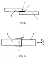
- Fig. 1a and 1b a schematic representation of the insulation layer in a screwed connection construction
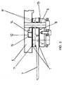
- Fig. 2 the installation position of the insulation according to the invention between bogie frame and axle box of a rail vehicle in a schematic representation
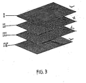
- Fig. 3 the basic structure of the insulating layer of the device according to the invention.
- Fig. 4 an example of a glued to the bogie frame tooth plate with insulation layer
- the Fig. 1a and 1b show schematically the arrangement of the insulation layer 1 according to the invention between two interconnected by at least one screw connection parts 2 and 3, in which the current transfer from Part 1 to Part 2 or vice versa should be effectively prevented and at the same time large forces must be transmitted.
- the Fig. 2 shows the installation position of such in Fig. 1a and 1b explained isolation layer 1 between a bogie frame 5 and a pressure plate 6 of a rail vehicle not shown.
- the axle guide 7 has at its one end 8 a toothing 10 which extends transversely to the longitudinal direction of the axle guide 7 and which engages in a toothing of the toothed plate 11 which is fixed to the bogie frame 5 by means of a toothed plate 11 formed on the pin 12.
- the end toothing 10 of the end 8 of the axle guide 7 and the tooth plate 11 are arranged between bogie frame 5 and pressure plate 6 and are held in position by a pressure plate 6, the end 8 of the axle guide 7 and the bogie frame 5 passing through bolt 13.
- the bogie frame 5 facing top surface DF of the square tooth plate 11 made of steel is a 1 mm thick insulating layer 1 of a composite of epoxy resin and embedded in the resin matrix fabric layer of glass filament with a diameter between 4 and 17 microns and a Weight per unit area up to 580 g / m 2 glued on.
- the resin composition of the composite can reach up to about 570 g / m 2 depending on the requirements.
- suitable resins such as polyamide, polyester or phenolic resins.
- the structure of the composite can be varied according to the requirements placed on the connection.
- a reaction adhesive is used, which corresponds to the resin quality and the hardener of the composite.
- the insulating layer 1 has such a dimension that the insulating layer 1 overhangs the top surface DF of the toothed plate 11 with a circumferential projection Ü. It has proved to be advantageous that the supernatant Ü is approximately between 1 and 3 mm. This prevents current transmission due to creepage currents due to contamination.
- the tooth plate 11 with the glued insulation layer 1 is then also bonded by means of a corresponding reaction adhesive on the bogie frame 5.
- the intended for the bonding area of the bogie frame 5 is previously cleaned and applied reactive adhesive to this area.
- the pin 14 provided with the pin 12 of the tooth plate 11 in the correspondingly provided receiving bore 15 in Bogie frame 5 is inserted, so that not only the tooth plate 11 is electrically insulated by the insulating layer 1 from the bogie frame 5, but also the pin 12 of the tooth plate 11 through the sleeve 14 relative to the bogie frame 5.
- the insulation value of the insulating layer 1 and the sleeve 14 in this example reaches values of 1 G ⁇ .
- the pressure plate 6 On the side facing away from the teeth 10 of the axle guide 7 of the pressure plate of the axle guide 7, the pressure plate 6 is arranged on the same as a 1 mm thick insulation layer 1 of a composite of epoxy resin and embedded in the resin matrix fabric layer of glass filament with a diameter between 4 and 17 microns and a basis weight up to 580 g / m 2 is adhered, so that a current transition from the wishbone 7 in the unillustrated cylindrical roller bearing of the wheel bearing is reliably prevented.
- the guided through holes 16 in the tooth plate 11, wishbone 7 and pressure plate 6 bolt 13 is isolated by a two-piece sleeve 17 made of polytetrafluoroethylene with a wall thickness of 2 mm with respect to the tooth plate 11, pressure plate 6 and axle guide 7, so that a current transfer from axle guide. 7 is excluded on the wheel bearing housing.
- the Fig. 4 shows a fixed by gluing on the bogie frame 5 tooth plate 11th
Landscapes
- Engineering & Computer Science (AREA)
- Mechanical Engineering (AREA)
- Laminated Bodies (AREA)
- Cable Accessories (AREA)
- Braking Arrangements (AREA)
- Coupling Device And Connection With Printed Circuit (AREA)
- Resistance Heating (AREA)
- Apparatus For Radiation Diagnosis (AREA)
- Railway Tracks (AREA)
Abstract
Description
- Die Erfindung betrifft eine Vorrichtung zur Isolation einer auf Zug-, Druck und Schub beanspruchten Verbindung zwischen stromableitenden Bauteilen eines Schienenfahrzeuge mit einem Drehgestellrahmen und einem Achslenker, der mittels einer zwischen Druckplatte und Drehgestellrahmen angeordneten Zahnplatte durch mindestens eine Verschraubung kraftschlüssig am Drehgestellrahmen befestigt ist, wobei eine Verzahnung am Ende des Achslenkers in die Verzahnung der Zahnplatte verrastend angeordnet ist.
Stand der Technik - Aus dem Stand der Technik (
DE 847 918 C ,DE 1 290 944 A1 ,DE 23 54 434 A1 ,DE 24 22 999 A1 ,DE 25 40 662 A1 ,DE 31 37 542 C2 ) ist es bekannt, den Achslenker zahnleistenartig zwischen Drehgestellrahmen und Radlagergehäuse mittels einer Verschraubung zu befestigen. GemäßDE 24 22 999 A1 sind die Enden des Achslenkerblattes mit einer Verzahnung versehen, die festbockseitig in die Verzahnung einer an den mit dem Drehgestellrahmen fest verbundenen Festblock und achsbuchalagerseitig in die Verzahnung eines oberen Gummi-Metall-Elements eingreift. Die gesamte Baueinheit ist achsbuchelagerseitig durch eine Dehnschraube, eine Mutter und eine Gegenmutter fest mit dem Achslagergehäuse verbunden. Sowohl die festbockseitige Verzahnung als auch die achsbuchslagerseitige Verbindung ist nicht gegen Stromfluss isoliert, so dass eine Schädigung der Zylinderrollenlager an den Radsätzen nicht auszuschließen ist. - Man hat versucht diese Nachteile durch eine keramische Schutzschicht, beispielsweise eine Beschichtung mit Aluminiumoxid, zu beseitigen. Die keramischen Beschichtungen haben jedoch den Nachteil, dass sie bei plötzlichen Schlag- und Druckbeanspruchungen, insbesondere an den scharfkantigen Übergängen der Druck- und Zahnplatten unter Last zur Rissbildung neigen, was die Isolationseigenschaften der Zahn- und Druckplatten gegen Stromfluss nachhaltig verschlechtern.
Außerdem sind die Keramikschichten empfindlich bei der Montage und teuer. - Bei diesem Stand der Technik liegt der Erfindung die Aufgabe zugrunde, die eingangs genannte Vorrichtung derart zu verbessern, dass die auf Zug, Druck und Schub beanspruchte Verbindung bei hoher Druckfestigkeit und geringer Gleitfestigkeit auch unter Belastung ihre hochisolierende Eigenschaften langfristig unter gleichzeitiger Reduzierung der Kosten bei ihrer Herstellung mit hoher Wartungsfreundlichkeit gewährleistet.
- Diese Aufgabe wird durch eine Vorrichtung der eingangs genannten Gattung mit den Merkmalen des Anspruches 1 gelöst.
- Vorteilhafte Ausgestaltungen der Vorrichtung sind den Unteransprüchen entnehmbar.
- Die erfindungagemäße Lösung ermöglicht es, eine gegen unerwünschten Stromfluss hochisolierte Verbindung von unter Zug, Druck und Schub stehenden Bauteilen, insbesondere Drehgestellrahmen und Achslenker eines Schienenfahrzeuges bereitzustellen.
Dies hat den außerordentlichen Vorteil, dass die durch den Stromfluss versursachte Schädigung der Zylinderrollenlager an den Radsätzen sicher beseitigt wird. Die zwischen Drehgestellrahmen und Druckplatte angeordneten Isolationslagen sind gegen Stromfluss hochisolierend, druckfest und haben einen gegenüber Metallen sehr geringen Reibwertkoeffizienten, so dass die Kräfte ohne ein Querfließen der Isolationslagen wesentlich besser übertragen werden können. - Die erfindungsgemäße Vorrichtung hat einen robusten Aufbau und ist gleichzeitig wartungs-, montage- und reparaturfreundlich. Von besonderem Vorteil ist, dass kostengünstige handelsübliche Schicht- oder Verbundwerkstoffe als Isolationslage zum Einsatz kommen können, ohne dass aufwändige und teure Beschichtungen der Zahn- und Druckplatten notwendig sind.
- Die Druck- und Zahnplatten weisen zur Isolation auf ihren jeweils dem Drehgestellrahmen bzw. Achslenker zugewandten Seitenflächen eine durch Klebung stoffschlüssig gehaltene Isolationslage eines Verbundes aus Glasfaserfilament und Harz auf, wobei die Isolationslage jeweils durch Klebung am Drehgestellrahmen bzw. Achslenker gehalten ist, und dass die mindestens eine Verschraubung durch eine Hülse aus Polytetrafluoräthylen isolierend umschlossen ist.
- Die entsprechenden Isolationslagen lassen sich in einfacher Weise auf den Oberflächen der Zahn- bzw. Druckplatte durch Verkleben mit einem Reaktionsharz befestigen, der der Harzmatrix der Isolationslage entspricht, so dass eine sichere Isolation von Drehgestell und Zahnplatte bzw. Achslenker und Druckplatte gewährleistet ist.
- Die Isolationslage hat eine Dicke zwischen 0,8 und 3 mm und weist gegenüber den Abmessungen der Deckflächen von Druck- und Zahnplatte einen deutlichen umlaufenden Überstand von etwa 1 bis 3 mm auf. Dies hat den Vorteil, dass Kriechströme auch bei äußerer Verschmutzung, beispielsweise Feuchtigkeit, sicher verhindert werden können und die Isolationseigenschaft der Verbindung erhalten bleibt.
- Die Isolationslage besteht in einer bevorzugten Ausgestaltung der Erfindung aus dem Verbund aus Harz und einer in die Harzmatrix eingebetteten Gewebelage aus Glasfilament mit einem Durchmesser zwischen 4 und 17 µm und einem Flächengewicht von bis zu 580 g/m2, wobei der Harzmassenanteil etwa 570 g/m2 erreichen kann.
- Eine weitere zweckmäßige Ausgestaltung der erfindungsgemäßen Isolierung sieht vor, dass sich der Verbund aus mit Harz imprägnierten und durch das Harz miteinander verbundenen Gewebelagen, und zwar mindestens zwei übereinander angeordneten, aus 0°/90° zueinander verlegten Gewebelagen mit einem Flächengewicht von 160 bis 280 g/m2, zusammensetzt, wobei der Harzmassenanteil 322 bis 552 g/m2 beträgt.
- In weiterer Ausgestaltung der Erfindung kann die Isolationslagen auch aus vier mit Harz imprägnierten und durch das Harz miteinander verbundenen Gewebelagen zusammengesetzt sein, und zwar aus einer aus 0°/90° zueinander verlegten ersten Gewebelage mit einem Flächengewicht von 163 bis 580 g/m2, einer aus 45°/45° zur ersten Gewebelage angeordneten zweiten und dritten Gewebelage mit einem Flächengewicht von 163 bis 580 g/m2 und einer aus 0°/90° zueinander verlegten vierten Gewebelage mit einem Flächengewicht von 163 bis 580 g/m2, wobei der Harzmassenanteil zwischen 161 bis 573 g/m2 je Lage beträgt.
- Es gehört jedoch auch zu der Erfindung, wenn die Isolationslage aus drei mit Harz imprägnierten und durch das Harz miteinander verbundenen Gewebelagen besteht, und zwar aus einer aus 0°/90° zueinander verlegten ersten Gewebelage mit einem Flächengewicht von 163 bis 580 g/m2, einer aus 45°/45° zur ersten Gewebelage angeordneten zweiten Gewebelage mit einem Flächengewicht von 163 bis 530 g/m2 und einer aus 0°/90° zueinander verlegten dritten Gewebelage mit einem Flächengewicht von 163 bis 580 g/m2, wobei der Harzmassenanteil zwischen 161 bis 580 g/m2 je Lage liegen kann.
- Besonders gut zur Imprägnierung des Glasfaserfilamentgewebes ist Epoxidharz geeignet. Es gehört jedoch auch zur Erfindung, wenn andere geeignete Harze wie beispielsweise Polyamidharz, Phenolharz oder Polyesterharz verwendet werden.
- Von besonderem weiteren Vorteil ist, dass auch die Verschraubung von Drehgestellrahmen, Achslenker und Druckplatte durch eine Hülse aus Polytetrafluoräthylen mit einer Dicke von 1,5 bis 3 mm hoch isolierend ist, so dass ein Stromfluss über den Achslenker in die Zylinderrollenlager des Radlagers sicher verhindert wird.
- Die Besonderheit der erfindungsgemäßen Isolierung liegt darin, dass sie mit einem Isolationswert von 1 GΩ nicht nur hochisolierend gegen Stromübergang ist, sondern auch einen minimalen Gleitreibungskoeffizient von 0,15 bei Flächenpressungswerten von 60 N/mm2 erreicht, so dass die Axialkräfte der Schraubverbindung ohne nennenswerte Axialkräfte und ohne Fließen der Isolationslage auch bei Querkraftbeanspruchung aufgenommen werden können
- Weitere Vorteile und Einzelheiten ergeben sich aus der nachfolgenden Beschreibung unter Bezugnahme auf die beigefügten Zeichnungen.
- Die Erfindung soll nachstehend an einem Ausführungsbeispiel näher erläutert werden. Es zeigt
-
Fig. 1a und 1b eine Prinzipdarstellung der Isolationslage in einer verschraubten Verbindungekonstruktion, -
Fig. 2 die Einbaulage der erfindungsgemäßen Isolierung zwischen Drehgestellrahmen und Achslagergehäuse eines Schienenfahrzeugs in schematischer Darstellung, -
Fig. 3 den prinzipiellen Aufbau der Isolationslage der erfindungsgemäßen Vorrichtung und -
Fig. 4 ein Beispiel einer mit dem Drehgestellrahmen verklebten Zahnplatte mit Isolationslage, - Die
Fig. 1a und 1b zeigen schematisch die Anordnung der erfindungsgemäßen isolationslage 1 zwischen zwei durch mindestens eine Verschraubung miteinander verbundenen Teilen 2 und 3, in denen der Stromübergang vom Teil 1 auf Teil 2 oder umgekehrt wirksam verhindert werden soll und gleichzeitig große Kräfte übertragen werden müssen. Die Isolationslage 1 muss dabei einen sehr hohen Isolationswert im MΩ-Bereich in Abhängigkeit von ihrer gewählten Dicke besitzen, eine zulässige Flächenpressung von mindestens 60 N/mm2 erreichen, um die Axialkräfte der Schraubverbindung 4 ohne nennenswerte Elastizität und ohne ein Fließen der Isolationslage in Querrichtung aufnehmen zu können, einen minimalen Gleitreibungskoeffizienten von µ= 0,15 haben, um die notwendige Gleitfestigkeit bei Querbeanspruchung (siehe Kraftkomponenten F in Fig. lb) der Schraubverbindung zu gewährleisten und hinreichende Isolationseigenschaften auch bei Verschmutzung der Verschraubung zu sichern. - Die
Fig. 2 zeigt die Einbaulage einer solchen inFig. 1a und 1b erläuterten Isolationslage 1 zwischen einem Drehgestellrahmen 5 und einer Druckplatte 6 eines nicht weiter gezeigten Schienenfahrzeugs.
Der Achslenker 7 weist an seinem eine Ende 8 eine Verzahnung 10 auf, die quer zur Längsrichtung des Achslenkers 7 verläuft und welche in eine Verzahnung der Zahnplatte 11 eingreift, die am Drehgestellrahmen 5 mittels eines an der Zahnplatte 11 angeformten Zapfens 12 fixiert ist. Die endseitige Verzahnung 10 des Endes 8 des Achslenkers 7 und die Zahnplatte 11 sind zwischen Drehgestellrahmen 5 und Druckplatte 6 angeordnet und werden in ihrer Lage durch einen die Druckplatte 6, das Ende 8 des Achslenkers 7 und den Drehgestellrahmen 5 durchsetzenden Schraubbolzen 13 gehalten. - Auf die zuvor durch Sandstrahlen gereinigte, dem Drehgestellrahmen 5 zugewandte Deckfläche DF der quadratischen Zahnplatte 11 aus Stahl ist eine 1 mm dicke Isolationslage 1 aus einem Verbund aus Epoxidharz und einer in die Harzmatrix eingebetteten Gewebelage aus Glasfilament mit einem Durchmesser zwischen 4 und 17 µm und einem Flächengewicht bis zu 580 g/m2 aufgeklebt. Der Harzmassenanteil des Verbundes kann je nach Anforderung bis etwa 570 g/m2 erreichen. Natürlich ist es auch möglich, andere geeignete Harze wie Polyamid-, Polyester- oder Phenolharze zu verwenden. Ebenso kann der Aufbau des Verbundes entsprechend den an die Verbindung gestellten Erfordernissen variiert werden. So ist es beispielsweise möglich, mehrlagige Verbunde mit gleicher oder unterschiedlicher Ausrichtung der Gewebelagen des Glasfaserfilamentes unter Variation des Harzmassenanteils einzusetzen. Als besonders geeignet haben sich Verbunde aus Hartfaserfilamnentgewebe mit der Bezeichnung HGW 2372.2 nach EP GV 203 erwiesen. Ein Beispiel des Aufbaus eines solchen mehrlagigen Verbunden zeigt
Fig. 3 , aus der man deutlich die unterschiedliche Orientierung der zweiten und dritten Gewebelage II und III gegenüber der ersten Gewebelage I und der vierten Gewebelage IV erkennen kann.
Die Flächengewichte der einzelnen Gewebelagen liegen zwischen 163 bis 580 g/m2 und der Harzmassenanteil zwischen 161 bis 572 g/m2. Als Kleber für die Verklebung von Zahnplatte 11 und Isolationslage 1 kommt ein Reaktionskleber zum Einsatz, der der Harzqualität und des Härters des Verbundes entspricht. Die Isolationslage 1 hat eine solche Abmessung, dass die Isolationslage 1 die Deckfläche DF der Zahnplatte 11 mit einem umlaufenden Überstand Ü überkragt. Es hat sich als vorteilhaft erwiesen, dass der Überstand Ü etwa zwischen 1 und 3 mm beträgt. Dies verhindert eine Stromübertragung durch Kriechströme infolge von Verschmutzung. Nachdem der Reaktionskleber ausgehärtet ist, wird auf den an der Zahnplatte 11 angeformten Zapfen 12 eine Hülse 14 aus Polytetrafluoräthylen mit einer Wanddicke von 2 mm aufgeschoben. Die Zahnplatte 11 mit der aufgeklebten Isolationslage 1 wird sodann ebenso mittels eines entsprechenden Reaktionsklebers am Drehgestellrahmen 5 verklebt. Der für die Verklebung vorgesehene Bereich des Drehgestellrahmens 5 wird zuvor gereinigt und Reaktionskleber auf diesen Bereich aufgebracht. Anschließend wird der mit der Hülse 14 versehene zapfen 12 der Zahnplatte 11 in die entsprechend vorgesehene Aufnahmebohrung 15 im Drehgestellrahmen 5 eingeschoben, so dass nicht nur die Zahnplatte 11 durch die Isolationslage 1 elektrisch vom Drehgestellrahmen 5, sondern auch der zapfen 12 der zahnplatte 11 durch die Hülse 14 gegenüber dem Drehgestellrahmen 5 isoliert ist. Der Isolationswert der Isolationslage 1 und der Hülse 14 erreicht in diesem Beispiel Werte von 1 GΩ. - Auf die der Verzahnung 10 des Achslenkers 7 der Druckplatte des Achslenkers 7 abgewandten Seite ist die Druckplatte 6 angeordnet, auf die ebenso eine 1 mm dicke Isolationslage 1 aus einem Verbund aus Epoxidharz und einer in die Harzmatrix eingebetteten Gewebelage aus Glasfilament mit einem Durchmesser zwischen 4 und 17 µm und einem Flächengewicht bis zu 580 g/m2 aufgeklebt wird, so dass auch ein Stromübergang vom Achslenker 7 in das nicht dargestellte Zylinderrollenlager des Radlagers sicher verhindert wird.
- Der durch Bohrungen 16 in der Zahnplatte 11, Achslenker 7 und Druckplatte 6 geführte Schraubbolzen 13 wird durch eine zweiteilige Hülse 17 aus Polytetrafluoräthylen mit einer Wanddicke von 2 mm gegenüber der Zahnplatte 11, Druckplatte 6 und Achslenker 7 isoliert, so dass ein Stromübergang vom Achslenker 7 auf das Radlagergehäuse ausgeschlossen ist.
- Die
Fig. 4 zeigt eine durch Klebung am Drehgestellrahmen 5 befestigte Zahnplatte 11. - Bezugszeichenliste
Hierzu 4 Blatt Zeichnungen Isolationslage 1 Teile einer Schraubverbindung 2, 3 Schraubverbindung 4 Drehgestellrahmen 5 Druckplatte 6 Achslenker 7 Endes des Achslenkers 8 Verzahnung der Zahnplatte 11 9 Verzahnung am Ende 8 von 7 10 Zahnplatte 11 Zapfen von 11 12 Schraubbolzen 13 13 Hülse für Zapfen 12 14 Aufnahmebohrung in 5 15 Bohrungen in 6, 7, 11 16 Hülse für 13 17 Deckfläche von 6, 11 DF Kraftkomponenten F Überstand von 1 Ü Gewebelagen I,II,III,IV
Claims (13)
- Vorrichtung zur Isolation einer auf Zug-, Druck und Schub beanspruchten Verbindung zwischen stromableitenden Bauteilen eines Schienenfahrzeuge mit einem Drehgestellrahmen (5) und einem Achslenker (7), der mittels einer zwischen Druckplatte (6) und Drehgestellrahmen (5) angeordneten Zahnplatte (11 ) durch mindestens eine Verschraubung (13) kraftschlüssig am Drehgestellrahmen (5) befestigt ist, wobei eine Verzahnung (10) am Ende (8) des Achslenkers (7) in eine Verzahnung (9) der Zahnplatte (11) verrastend angeordnet ist, dadurch gekennzeichnet, dass die Zahnplatte (11) und die Druckplatte (6) auf ihren jeweils gegenüber dem Drehgestellrahmen (5) bzw. Ende (8) des Achslenkers (7) zugewandten Deckflächen (DF) eine durch eine Klebung stoffschlüssig gehaltenen Isolationslage (1) eines 0,8 bis 3 mm dicken Verbundes aus Glasfaserfilament und Harz aufweisen, wobei die Isolationslagen (1) jeweils zusätzlich durch Klebung am Drehgestellrahmen (5) bzw. Ende (8) des Achslenkers (7) stoffschlüssig gehalten sind, und dass die mindestens eine Verschraubung (13) durch eine isolierend Hülse (17) aus Polytetrafluoräthylen umschlossen ist.
- Vorrichtung nach Anspruch 1, dadurch gekennzeichnet, dass die Isolationslage (1) gegenüber den Abmessungen der Deckflächen von Druckplatte (6) bzw. Zahnplatte (11) jeweils einen umlaufenden Überstand (Ü) von 1 bis 3 mm besitzt.
- Vorrichtung nach Anspruch 1, dadurch gekennzeichnet, dass die Klebung von Isolationslage (1) und Druck- bzw. Zahnplatte (6,11) aus einem Reaktionskleber besteht.
- Vorrichtung nach Anspruch 1 bis 3, dadurch gekennzeichnet, dass der Reaktionskleber aus einem auf den Verbund abgestimmten Harz und Härter besteht.
- Vorrichtung nach Anspruch 1, dadurch gekennzeichnet, dass das Glasfaserfilament des Verbundes einen Filamentdurchmesser von 4 bis 17 µm hat.
- Vorrichtung nach Anspruch 1, dadurch gekennzeichnet, dass der Verbund aus Harz und einer in die Harzmatrix eingebetteten Gewebelage aus Glasfilament mit einem Durchmesser zwischen 4 und 17 µm und einem Flächengewicht von 580 g/m2 besteht, wobei der Harzmassenanteil etwa 570 g/m2 beträgt
- Vorrichtung nach Anspruch 1, dadurch gekennzeichnet, dass sich der Verbund aus mit Harz imprägnierten und durch das Harz miteinander verbundenen Gewebelagen, und zwar mindestens zwei übereinander angeordneten, aus 0°/90° zueinander verlegten Gewebelagen mit einem Flächengewicht von 160 bis 280 g/m2, zusammensetzt, wobei der Harzmassenanteil 322 bis 552 g/m2 beträgt.
- Vorrichtung nach Anspruch 1, dadurch gekennzeichnet, dass der Verbund aus drei mit Harz imprägnierten und durch das Harz miteinander verbundenen Gewebelagen besteht, und zwar aus einer aus 0°/90° zueinander verlegten ersten Gewebelage (I) mit einem Flächengewicht von 163 bis 580 g/m2, einer aus 45°/45° zur ersten Gewebelage (I) angeordneten zweiten Gewebelage (II) mit einem Flächengewicht von 163 bis 580 g/m2 und einer aus 0°/90° zueinander verlegten dritten Gewebelage (III) mit
einem Flächengewicht von 163 bis 580 g/m2, zusammensetzt, wobei der Harzmassenanteil zwischen 161 bis 580 g/m2 je Lage beträgt. - Vorrichtung nach Anspruch 1, dadurch gekennzeichnet, dass der Verbund aus vier mit Harz imprägnierten und durch das Harz miteinander verbundenen Gewebelagen zusammengesetzt ist, und zwar aus einer aus 0°/90° zueinander verlegten ersten Gewebelage (I) mit einem Flächengewicht von 163 bis 580 g/m2, einer aus 45°/45° zur ersten Gewebelage angeordneten zweiten und dritten Gewebelage (II,III) mit einem Flächengewicht von 163 bis 580 g/m2 und einer aus 0°/90° zueinander verlegten vierten Gewebelage (IV) mit einem Flächengewicht von 163 bis 580 g/m2, zusammensetzt, wobei der Harzmassenanteil zwischen 161 bis 573 g/m2 je Lage beträgt.
- Vorrichtung nach Anspruch 1 bis 9, dadurch gekennzeichnet, dass das zur Imprägnierung des Glasfaserfilamentgewebes verwendete Harz ein Epoxidharz, Polymidharz, Phenolharz oder Polyesterharz ist.
- Vorrichtung nach Anspruch 1, dadurch gekennzeichnet, dass die Hülsen (14,17) aus Polytetrafluoräthylen eine Dicke von 1,5 bis 3 mm aufweisen.
- Vorrichtung nach Anspruch 1 und 11, dadurch gekennzeichnet, dass die Hülse (17) mehrteilig, insbesondere zweiteilig, ausgebildet ist.
- Vorrichtung nach Anspruch 1 und 11, dadurch gekenazeichnet, dass der Isolationslage (1) und die Hülse (14, 17) einen Isolationswert von mindestens 1 GΩ, eine Flächenpressung von 60 N/mm2 und einen minimalen Gleitreibungekoeffizienten gegen Metall von 0,15 aufweist.
Priority Applications (2)
| Application Number | Priority Date | Filing Date | Title |
|---|---|---|---|
| PL09006055T PL2116441T3 (pl) | 2008-05-11 | 2009-05-03 | Urządzenie do zamkniętej siłowo izolacji połączeń przewodzących prąd |
| SI200930006T SI2116441T1 (sl) | 2008-05-11 | 2009-05-03 | Naprava za silosklepno izoliranje povezav ki prenašajo tok |
Applications Claiming Priority (1)
| Application Number | Priority Date | Filing Date | Title |
|---|---|---|---|
| DE102008023165A DE102008023165A1 (de) | 2008-05-11 | 2008-05-11 | Vorrichtung zur kraftschlüssigen Isolation von stromübertragenden Verbindungen |
Publications (2)
| Publication Number | Publication Date |
|---|---|
| EP2116441A1 true EP2116441A1 (de) | 2009-11-11 |
| EP2116441B1 EP2116441B1 (de) | 2010-06-30 |
Family
ID=41501002
Family Applications (1)
| Application Number | Title | Priority Date | Filing Date |
|---|---|---|---|
| EP09006055A Active EP2116441B1 (de) | 2008-05-11 | 2009-05-03 | Vorrichtung zur kraftschlüssigen Isolation von stromübertragenden Verbindungen |
Country Status (7)
| Country | Link |
|---|---|
| EP (1) | EP2116441B1 (de) |
| AT (1) | ATE472453T1 (de) |
| DE (2) | DE102008023165A1 (de) |
| ES (1) | ES2348426T3 (de) |
| PL (1) | PL2116441T3 (de) |
| PT (1) | PT2116441E (de) |
| SI (1) | SI2116441T1 (de) |
Cited By (1)
| Publication number | Priority date | Publication date | Assignee | Title |
|---|---|---|---|---|
| CN101927297A (zh) * | 2010-07-19 | 2010-12-29 | 奇瑞汽车股份有限公司 | 冲压模具的可调限位机构 |
Citations (9)
| Publication number | Priority date | Publication date | Assignee | Title |
|---|---|---|---|---|
| GB565984A (en) * | 1943-01-18 | 1944-12-07 | British Industrial Plastics | Improvements in or relating to laminated electrical insulating materials |
| DE847918C (de) | 1951-02-04 | 1952-08-28 | Ver Westdeutsche Waggonfabrike | Einstellbarer Achslenker, insbesondere fuer Schienenfahrzeuge |
| DE1290944B (de) | 1962-06-29 | 1969-03-20 | Waggonbau Veb | Federblatt-Achslenker, insbesondere fuer Drehgestelle von Schienenfahrzeugen mit Schraubenfedern als Achsfederung |
| DE2354434A1 (de) | 1973-09-17 | 1975-03-27 | Goerlitz Waggonbau Veb | Zahnleistenverbindung, insbesondere fuer federblatt-achslenker von schienenfahrzeugen |
| DE2422999A1 (de) | 1974-05-13 | 1975-11-27 | Kloeckner Humboldt Deutz Ag | Einstellbares achslenkerblatt, insbesondere fuer schienenfahrzeuge |
| DE2540662A1 (de) | 1974-12-03 | 1976-06-10 | Goerlitz Waggonbau Veb | Federblatt-achslenkerbefestigung fuer schienenfahrzeug-drehgestelle |
| DE3137542C2 (de) | 1981-09-22 | 1986-10-02 | MAN Gutehoffnungshütte GmbH, 4200 Oberhausen | Radsatzlagerführung, insbesondere für Schienenfahrzeuge mit Drehgestellen |
| EP0363573A2 (de) * | 1988-10-14 | 1990-04-18 | Eurocopter Deutschland Gesellschaft mit beschränkter Haftung | Drehgestell |
| US4926757A (en) * | 1989-01-30 | 1990-05-22 | Amsted Industries Incorporated | Electrically grounded railway truck |
-
2008
- 2008-05-11 DE DE102008023165A patent/DE102008023165A1/de not_active Withdrawn
-
2009
- 2009-05-03 AT AT09006055T patent/ATE472453T1/de active
- 2009-05-03 DE DE502009000037T patent/DE502009000037D1/de active Active
- 2009-05-03 ES ES09006055T patent/ES2348426T3/es active Active
- 2009-05-03 PT PT09006055T patent/PT2116441E/pt unknown
- 2009-05-03 EP EP09006055A patent/EP2116441B1/de active Active
- 2009-05-03 PL PL09006055T patent/PL2116441T3/pl unknown
- 2009-05-03 SI SI200930006T patent/SI2116441T1/sl unknown
Patent Citations (9)
| Publication number | Priority date | Publication date | Assignee | Title |
|---|---|---|---|---|
| GB565984A (en) * | 1943-01-18 | 1944-12-07 | British Industrial Plastics | Improvements in or relating to laminated electrical insulating materials |
| DE847918C (de) | 1951-02-04 | 1952-08-28 | Ver Westdeutsche Waggonfabrike | Einstellbarer Achslenker, insbesondere fuer Schienenfahrzeuge |
| DE1290944B (de) | 1962-06-29 | 1969-03-20 | Waggonbau Veb | Federblatt-Achslenker, insbesondere fuer Drehgestelle von Schienenfahrzeugen mit Schraubenfedern als Achsfederung |
| DE2354434A1 (de) | 1973-09-17 | 1975-03-27 | Goerlitz Waggonbau Veb | Zahnleistenverbindung, insbesondere fuer federblatt-achslenker von schienenfahrzeugen |
| DE2422999A1 (de) | 1974-05-13 | 1975-11-27 | Kloeckner Humboldt Deutz Ag | Einstellbares achslenkerblatt, insbesondere fuer schienenfahrzeuge |
| DE2540662A1 (de) | 1974-12-03 | 1976-06-10 | Goerlitz Waggonbau Veb | Federblatt-achslenkerbefestigung fuer schienenfahrzeug-drehgestelle |
| DE3137542C2 (de) | 1981-09-22 | 1986-10-02 | MAN Gutehoffnungshütte GmbH, 4200 Oberhausen | Radsatzlagerführung, insbesondere für Schienenfahrzeuge mit Drehgestellen |
| EP0363573A2 (de) * | 1988-10-14 | 1990-04-18 | Eurocopter Deutschland Gesellschaft mit beschränkter Haftung | Drehgestell |
| US4926757A (en) * | 1989-01-30 | 1990-05-22 | Amsted Industries Incorporated | Electrically grounded railway truck |
Cited By (1)
| Publication number | Priority date | Publication date | Assignee | Title |
|---|---|---|---|---|
| CN101927297A (zh) * | 2010-07-19 | 2010-12-29 | 奇瑞汽车股份有限公司 | 冲压模具的可调限位机构 |
Also Published As
| Publication number | Publication date |
|---|---|
| DE502009000037D1 (de) | 2010-08-12 |
| EP2116441B1 (de) | 2010-06-30 |
| PL2116441T3 (pl) | 2010-11-30 |
| SI2116441T1 (sl) | 2010-11-30 |
| PT2116441E (pt) | 2010-09-29 |
| ES2348426T3 (es) | 2010-12-03 |
| DE102008023165A1 (de) | 2010-02-11 |
| ATE472453T1 (de) | 2010-07-15 |
Similar Documents
| Publication | Publication Date | Title |
|---|---|---|
| EP2126353A2 (de) | Verbindung von bauteilen einer windenenergieanlage | |
| EP2115086A1 (de) | Isoliermaterial für elektrische maschinen | |
| DE2720133A1 (de) | Faserverstaerktes bauteil aus kunststoff, insbesondere hubschrauber- rotorblatt | |
| DE102016007663A1 (de) | Rohrförmiger Faserverbundkörper mit integrierter stufenloser Längenverstellung | |
| DE102008019372A1 (de) | Transmissionswelle zur Übertragung eines Drehmomentes und /oder axialer Kräfte | |
| EP3423706B1 (de) | Windkraftanlage mit verbesserter rotorblattverschraubung | |
| DE202008008215U1 (de) | Krafteinleitungselement für Faserverbundstreben in Flugzeugen | |
| EP2116441B1 (de) | Vorrichtung zur kraftschlüssigen Isolation von stromübertragenden Verbindungen | |
| DE102011012938A1 (de) | Befestigungsanordnung eines Kunststoffteils an einem Rohbauteil eines Kraftwagens | |
| DE102012202172A1 (de) | Sitzbefestigung für einen Personensitz in einem Schienenfahrzeug | |
| EP3253973B1 (de) | Anordnung aus einem ersten und einem zweiten bauteil | |
| EP0967330B1 (de) | Zugstab zur Verwendung als Gurt für Brücken | |
| DE19713678A1 (de) | Klemmbeschlag für die Befestigung von Glasscheiben | |
| DE102011100334A1 (de) | Verbindungsanordnung für Bambusrohre | |
| DE202006001878U1 (de) | Krafteinleitungselement für Faserverbundstreben in Flugzeugen | |
| WO2013083347A1 (de) | Überspannungsableiter | |
| DE102018108695A1 (de) | Windenergieanlagen-Rotorblatt und Windenergieanlage | |
| DE102017003024A1 (de) | Abschlusselement zur Krafteinleitung in ein vorgefertigtes Faserkunststoffverbundrohr | |
| EP3116773A1 (de) | Verbundbauteil mit klemmsitz, insbesondere lenkerbügel oder sattelstütze | |
| EP2329504B1 (de) | Elektrische vorrichtung mit einem haltegerüst | |
| EP2255366B1 (de) | Zwei- oder mehrphasiger transformator | |
| DE202006016041U1 (de) | Krafteinleitungselement für Faserverbundstreben in Flugzeugen | |
| DE102015005207B4 (de) | Verschraubungsanordnung | |
| DE19800896C1 (de) | Einrichtung zum Einleiten einer Kraft in ein Element | |
| DE102013112974A1 (de) | Sandwichblechkonstruktion |
Legal Events
| Date | Code | Title | Description |
|---|---|---|---|
| PUAI | Public reference made under article 153(3) epc to a published international application that has entered the european phase |
Free format text: ORIGINAL CODE: 0009012 |
|
| AK | Designated contracting states |
Kind code of ref document: A1 Designated state(s): AT BE BG CH CY CZ DE DK EE ES FI FR GB GR HR HU IE IS IT LI LT LU LV MC MK MT NL NO PL PT RO SE SI SK TR |
|
| GRAP | Despatch of communication of intention to grant a patent |
Free format text: ORIGINAL CODE: EPIDOSNIGR1 |
|
| 17P | Request for examination filed |
Effective date: 20100119 |
|
| GRAS | Grant fee paid |
Free format text: ORIGINAL CODE: EPIDOSNIGR3 |
|
| GRAA | (expected) grant |
Free format text: ORIGINAL CODE: 0009210 |
|
| AK | Designated contracting states |
Kind code of ref document: B1 Designated state(s): AT BE BG CH CY CZ DE DK EE ES FI FR GB GR HR HU IE IS IT LI LT LU LV MC MK MT NL NO PL PT RO SE SI SK TR |
|
| REG | Reference to a national code |
Ref country code: CH Ref legal event code: EP Ref country code: GB Ref legal event code: FG4D Free format text: NOT ENGLISH |
|
| REG | Reference to a national code |
Ref country code: IE Ref legal event code: FG4D Free format text: LANGUAGE OF EP DOCUMENT: GERMAN |
|
| REF | Corresponds to: |
Ref document number: 502009000037 Country of ref document: DE Date of ref document: 20100812 Kind code of ref document: P |
|
| REG | Reference to a national code |
Ref country code: RO Ref legal event code: EPE |
|
| REG | Reference to a national code |
Ref country code: PT Ref legal event code: SC4A Free format text: AVAILABILITY OF NATIONAL TRANSLATION Effective date: 20100922 |
|
| REG | Reference to a national code |
Ref country code: CH Ref legal event code: NV Representative=s name: BOVARD AG PATENTANWAELTE |
|
| REG | Reference to a national code |
Ref country code: NL Ref legal event code: VDEP Effective date: 20100630 |
|
| PG25 | Lapsed in a contracting state [announced via postgrant information from national office to epo] |
Ref country code: LT Free format text: LAPSE BECAUSE OF FAILURE TO SUBMIT A TRANSLATION OF THE DESCRIPTION OR TO PAY THE FEE WITHIN THE PRESCRIBED TIME-LIMIT Effective date: 20100630 Ref country code: NO Free format text: LAPSE BECAUSE OF FAILURE TO SUBMIT A TRANSLATION OF THE DESCRIPTION OR TO PAY THE FEE WITHIN THE PRESCRIBED TIME-LIMIT Effective date: 20100930 Ref country code: SE Free format text: LAPSE BECAUSE OF FAILURE TO SUBMIT A TRANSLATION OF THE DESCRIPTION OR TO PAY THE FEE WITHIN THE PRESCRIBED TIME-LIMIT Effective date: 20100630 |
|
| REG | Reference to a national code |
Ref country code: ES Ref legal event code: FG2A Effective date: 20101123 |
|
| LTIE | Lt: invalidation of european patent or patent extension |
Effective date: 20100630 |
|
| PG25 | Lapsed in a contracting state [announced via postgrant information from national office to epo] |
Ref country code: LV Free format text: LAPSE BECAUSE OF FAILURE TO SUBMIT A TRANSLATION OF THE DESCRIPTION OR TO PAY THE FEE WITHIN THE PRESCRIBED TIME-LIMIT Effective date: 20100630 Ref country code: HR Free format text: LAPSE BECAUSE OF FAILURE TO SUBMIT A TRANSLATION OF THE DESCRIPTION OR TO PAY THE FEE WITHIN THE PRESCRIBED TIME-LIMIT Effective date: 20100630 Ref country code: FI Free format text: LAPSE BECAUSE OF FAILURE TO SUBMIT A TRANSLATION OF THE DESCRIPTION OR TO PAY THE FEE WITHIN THE PRESCRIBED TIME-LIMIT Effective date: 20100630 |
|
| REG | Reference to a national code |
Ref country code: PL Ref legal event code: T3 |
|
| PG25 | Lapsed in a contracting state [announced via postgrant information from national office to epo] |
Ref country code: EE Free format text: LAPSE BECAUSE OF FAILURE TO SUBMIT A TRANSLATION OF THE DESCRIPTION OR TO PAY THE FEE WITHIN THE PRESCRIBED TIME-LIMIT Effective date: 20100630 Ref country code: NL Free format text: LAPSE BECAUSE OF FAILURE TO SUBMIT A TRANSLATION OF THE DESCRIPTION OR TO PAY THE FEE WITHIN THE PRESCRIBED TIME-LIMIT Effective date: 20100630 |
|
| REG | Reference to a national code |
Ref country code: IE Ref legal event code: FD4D |
|
| PG25 | Lapsed in a contracting state [announced via postgrant information from national office to epo] |
Ref country code: CY Free format text: LAPSE BECAUSE OF FAILURE TO SUBMIT A TRANSLATION OF THE DESCRIPTION OR TO PAY THE FEE WITHIN THE PRESCRIBED TIME-LIMIT Effective date: 20100630 Ref country code: IS Free format text: LAPSE BECAUSE OF FAILURE TO SUBMIT A TRANSLATION OF THE DESCRIPTION OR TO PAY THE FEE WITHIN THE PRESCRIBED TIME-LIMIT Effective date: 20101030 Ref country code: SK Free format text: LAPSE BECAUSE OF FAILURE TO SUBMIT A TRANSLATION OF THE DESCRIPTION OR TO PAY THE FEE WITHIN THE PRESCRIBED TIME-LIMIT Effective date: 20100630 |
|
| REG | Reference to a national code |
Ref country code: CH Ref legal event code: PFA Owner name: BERLINER VERKEHRSBETRIEBE (BVG) Free format text: BERLINER VERKEHRSBETRIEBE (BVG)#ANSTALT DES OEFFENTLICHEN RECHTS POTSDAMER STR. 188#10773 BERLIN (DE) -TRANSFER TO- BERLINER VERKEHRSBETRIEBE (BVG)#ANSTALT DES OEFFENTLICHEN RECHTS POTSDAMER STR. 188#10773 BERLIN (DE) |
|
| PG25 | Lapsed in a contracting state [announced via postgrant information from national office to epo] |
Ref country code: DK Free format text: LAPSE BECAUSE OF FAILURE TO SUBMIT A TRANSLATION OF THE DESCRIPTION OR TO PAY THE FEE WITHIN THE PRESCRIBED TIME-LIMIT Effective date: 20100630 Ref country code: IE Free format text: LAPSE BECAUSE OF FAILURE TO SUBMIT A TRANSLATION OF THE DESCRIPTION OR TO PAY THE FEE WITHIN THE PRESCRIBED TIME-LIMIT Effective date: 20100630 |
|
| PLBE | No opposition filed within time limit |
Free format text: ORIGINAL CODE: 0009261 |
|
| STAA | Information on the status of an ep patent application or granted ep patent |
Free format text: STATUS: NO OPPOSITION FILED WITHIN TIME LIMIT |
|
| PG25 | Lapsed in a contracting state [announced via postgrant information from national office to epo] |
Ref country code: GR Free format text: LAPSE BECAUSE OF FAILURE TO SUBMIT A TRANSLATION OF THE DESCRIPTION OR TO PAY THE FEE WITHIN THE PRESCRIBED TIME-LIMIT Effective date: 20101001 |
|
| 26N | No opposition filed |
Effective date: 20110331 |
|
| REG | Reference to a national code |
Ref country code: DE Ref legal event code: R097 Ref document number: 502009000037 Country of ref document: DE Effective date: 20110330 |
|
| REG | Reference to a national code |
Ref country code: HU Ref legal event code: AG4A Ref document number: E010928 Country of ref document: HU |
|
| BERE | Be: lapsed |
Owner name: BERLINER VERKEHRSBETRIEBE (BVG) Effective date: 20110531 |
|
| PG25 | Lapsed in a contracting state [announced via postgrant information from national office to epo] |
Ref country code: MT Free format text: LAPSE BECAUSE OF FAILURE TO SUBMIT A TRANSLATION OF THE DESCRIPTION OR TO PAY THE FEE WITHIN THE PRESCRIBED TIME-LIMIT Effective date: 20100630 Ref country code: MC Free format text: LAPSE BECAUSE OF NON-PAYMENT OF DUE FEES Effective date: 20110531 |
|
| PG25 | Lapsed in a contracting state [announced via postgrant information from national office to epo] |
Ref country code: BE Free format text: LAPSE BECAUSE OF NON-PAYMENT OF DUE FEES Effective date: 20110531 |
|
| PG25 | Lapsed in a contracting state [announced via postgrant information from national office to epo] |
Ref country code: TR Free format text: LAPSE BECAUSE OF FAILURE TO SUBMIT A TRANSLATION OF THE DESCRIPTION OR TO PAY THE FEE WITHIN THE PRESCRIBED TIME-LIMIT Effective date: 20100630 Ref country code: BG Free format text: LAPSE BECAUSE OF FAILURE TO SUBMIT A TRANSLATION OF THE DESCRIPTION OR TO PAY THE FEE WITHIN THE PRESCRIBED TIME-LIMIT Effective date: 20100930 |
|
| REG | Reference to a national code |
Ref country code: FR Ref legal event code: PLFP Year of fee payment: 8 |
|
| REG | Reference to a national code |
Ref country code: FR Ref legal event code: PLFP Year of fee payment: 9 |
|
| REG | Reference to a national code |
Ref country code: FR Ref legal event code: PLFP Year of fee payment: 10 |
|
| PGFP | Annual fee paid to national office [announced via postgrant information from national office to epo] |
Ref country code: RO Payment date: 20200423 Year of fee payment: 12 Ref country code: PT Payment date: 20200420 Year of fee payment: 12 Ref country code: DE Payment date: 20200428 Year of fee payment: 12 Ref country code: LU Payment date: 20200520 Year of fee payment: 12 Ref country code: CH Payment date: 20200508 Year of fee payment: 12 Ref country code: ES Payment date: 20200609 Year of fee payment: 12 Ref country code: FR Payment date: 20200515 Year of fee payment: 12 Ref country code: CZ Payment date: 20200430 Year of fee payment: 12 |
|
| PGFP | Annual fee paid to national office [announced via postgrant information from national office to epo] |
Ref country code: PL Payment date: 20200421 Year of fee payment: 12 Ref country code: IT Payment date: 20200421 Year of fee payment: 12 Ref country code: HU Payment date: 20200504 Year of fee payment: 12 Ref country code: SI Payment date: 20200423 Year of fee payment: 12 Ref country code: GB Payment date: 20200630 Year of fee payment: 12 |
|
| PGFP | Annual fee paid to national office [announced via postgrant information from national office to epo] |
Ref country code: AT Payment date: 20200421 Year of fee payment: 12 |
|
| REG | Reference to a national code |
Ref country code: DE Ref legal event code: R119 Ref document number: 502009000037 Country of ref document: DE |
|
| REG | Reference to a national code |
Ref country code: CH Ref legal event code: PL |
|
| REG | Reference to a national code |
Ref country code: AT Ref legal event code: MM01 Ref document number: 472453 Country of ref document: AT Kind code of ref document: T Effective date: 20210503 |
|
| GBPC | Gb: european patent ceased through non-payment of renewal fee |
Effective date: 20210503 |
|
| PG25 | Lapsed in a contracting state [announced via postgrant information from national office to epo] |
Ref country code: HU Free format text: LAPSE BECAUSE OF NON-PAYMENT OF DUE FEES Effective date: 20210504 Ref country code: CZ Free format text: LAPSE BECAUSE OF NON-PAYMENT OF DUE FEES Effective date: 20210503 Ref country code: RO Free format text: LAPSE BECAUSE OF NON-PAYMENT OF DUE FEES Effective date: 20210503 Ref country code: PT Free format text: LAPSE BECAUSE OF NON-PAYMENT OF DUE FEES Effective date: 20211103 Ref country code: AT Free format text: LAPSE BECAUSE OF NON-PAYMENT OF DUE FEES Effective date: 20210503 Ref country code: CH Free format text: LAPSE BECAUSE OF NON-PAYMENT OF DUE FEES Effective date: 20210531 Ref country code: LI Free format text: LAPSE BECAUSE OF NON-PAYMENT OF DUE FEES Effective date: 20210531 Ref country code: LU Free format text: LAPSE BECAUSE OF NON-PAYMENT OF DUE FEES Effective date: 20210503 |
|
| PG25 | Lapsed in a contracting state [announced via postgrant information from national office to epo] |
Ref country code: SI Free format text: LAPSE BECAUSE OF NON-PAYMENT OF DUE FEES Effective date: 20210504 |
|
| REG | Reference to a national code |
Ref country code: SI Ref legal event code: KO00 Effective date: 20220125 |
|
| PG25 | Lapsed in a contracting state [announced via postgrant information from national office to epo] |
Ref country code: GB Free format text: LAPSE BECAUSE OF NON-PAYMENT OF DUE FEES Effective date: 20210503 Ref country code: DE Free format text: LAPSE BECAUSE OF NON-PAYMENT OF DUE FEES Effective date: 20211201 |
|
| PG25 | Lapsed in a contracting state [announced via postgrant information from national office to epo] |
Ref country code: FR Free format text: LAPSE BECAUSE OF NON-PAYMENT OF DUE FEES Effective date: 20210531 |
|
| REG | Reference to a national code |
Ref country code: ES Ref legal event code: FD2A Effective date: 20220801 |
|
| PG25 | Lapsed in a contracting state [announced via postgrant information from national office to epo] |
Ref country code: ES Free format text: LAPSE BECAUSE OF NON-PAYMENT OF DUE FEES Effective date: 20210504 |
|
| PG25 | Lapsed in a contracting state [announced via postgrant information from national office to epo] |
Ref country code: PL Free format text: LAPSE BECAUSE OF NON-PAYMENT OF DUE FEES Effective date: 20210503 Ref country code: IT Free format text: LAPSE BECAUSE OF NON-PAYMENT OF DUE FEES Effective date: 20200503 |
|
| PG25 | Lapsed in a contracting state [announced via postgrant information from national office to epo] |
Ref country code: IT Free format text: LAPSE BECAUSE OF NON-PAYMENT OF DUE FEES Effective date: 20210503 |