EP2115822B1 - Winkelsteckverbinder mit veränderbarer abgangsrichtung - Google Patents
Winkelsteckverbinder mit veränderbarer abgangsrichtung Download PDFInfo
- Publication number
- EP2115822B1 EP2115822B1 EP08706861A EP08706861A EP2115822B1 EP 2115822 B1 EP2115822 B1 EP 2115822B1 EP 08706861 A EP08706861 A EP 08706861A EP 08706861 A EP08706861 A EP 08706861A EP 2115822 B1 EP2115822 B1 EP 2115822B1
- Authority
- EP
- European Patent Office
- Prior art keywords
- housing
- sleeve
- housing flange
- flange
- plug
- Prior art date
- Legal status (The legal status is an assumption and is not a legal conclusion. Google has not performed a legal analysis and makes no representation as to the accuracy of the status listed.)
- Ceased
Links
- 229920002994 synthetic fiber Polymers 0.000 claims 1
- 230000002093 peripheral effect Effects 0.000 description 5
- 238000004519 manufacturing process Methods 0.000 description 4
- 239000000463 material Substances 0.000 description 4
- 238000005452 bending Methods 0.000 description 2
- 239000011248 coating agent Substances 0.000 description 2
- 238000000576 coating method Methods 0.000 description 2
- 241000209035 Ilex Species 0.000 description 1
- 229910000831 Steel Inorganic materials 0.000 description 1
- 238000005266 casting Methods 0.000 description 1
- 239000002131 composite material Substances 0.000 description 1
- 230000001419 dependent effect Effects 0.000 description 1
- 238000000034 method Methods 0.000 description 1
- 238000010561 standard procedure Methods 0.000 description 1
- 239000010959 steel Substances 0.000 description 1
Images


Classifications
-
- H—ELECTRICITY
- H01—ELECTRIC ELEMENTS
- H01R—ELECTRICALLY-CONDUCTIVE CONNECTIONS; STRUCTURAL ASSOCIATIONS OF A PLURALITY OF MUTUALLY-INSULATED ELECTRICAL CONNECTING ELEMENTS; COUPLING DEVICES; CURRENT COLLECTORS
- H01R13/00—Details of coupling devices of the kinds covered by groups H01R12/70 or H01R24/00 - H01R33/00
- H01R13/46—Bases; Cases
- H01R13/502—Bases; Cases composed of different pieces
- H01R13/5025—Bases; Cases composed of different pieces one or more pieces being of resilient material
-
- H—ELECTRICITY
- H01—ELECTRIC ELEMENTS
- H01R—ELECTRICALLY-CONDUCTIVE CONNECTIONS; STRUCTURAL ASSOCIATIONS OF A PLURALITY OF MUTUALLY-INSULATED ELECTRICAL CONNECTING ELEMENTS; COUPLING DEVICES; CURRENT COLLECTORS
- H01R13/00—Details of coupling devices of the kinds covered by groups H01R12/70 or H01R24/00 - H01R33/00
- H01R13/46—Bases; Cases
- H01R13/52—Dustproof, splashproof, drip-proof, waterproof, or flameproof cases
- H01R13/5202—Sealing means between parts of housing or between housing part and a wall, e.g. sealing rings
-
- H—ELECTRICITY
- H01—ELECTRIC ELEMENTS
- H01R—ELECTRICALLY-CONDUCTIVE CONNECTIONS; STRUCTURAL ASSOCIATIONS OF A PLURALITY OF MUTUALLY-INSULATED ELECTRICAL CONNECTING ELEMENTS; COUPLING DEVICES; CURRENT COLLECTORS
- H01R13/00—Details of coupling devices of the kinds covered by groups H01R12/70 or H01R24/00 - H01R33/00
- H01R13/73—Means for mounting coupling parts to apparatus or structures, e.g. to a wall
- H01R13/74—Means for mounting coupling parts in openings of a panel
- H01R13/748—Means for mounting coupling parts in openings of a panel using one or more screws
-
- H—ELECTRICITY
- H01—ELECTRIC ELEMENTS
- H01R—ELECTRICALLY-CONDUCTIVE CONNECTIONS; STRUCTURAL ASSOCIATIONS OF A PLURALITY OF MUTUALLY-INSULATED ELECTRICAL CONNECTING ELEMENTS; COUPLING DEVICES; CURRENT COLLECTORS
- H01R2107/00—Four or more poles
-
- Y—GENERAL TAGGING OF NEW TECHNOLOGICAL DEVELOPMENTS; GENERAL TAGGING OF CROSS-SECTIONAL TECHNOLOGIES SPANNING OVER SEVERAL SECTIONS OF THE IPC; TECHNICAL SUBJECTS COVERED BY FORMER USPC CROSS-REFERENCE ART COLLECTIONS [XRACs] AND DIGESTS
- Y10—TECHNICAL SUBJECTS COVERED BY FORMER USPC
- Y10S—TECHNICAL SUBJECTS COVERED BY FORMER USPC CROSS-REFERENCE ART COLLECTIONS [XRACs] AND DIGESTS
- Y10S439/00—Electrical connectors
- Y10S439/901—Connector hood or shell
- Y10S439/902—Angularly disposed contact and conductor
Definitions
- the invention relates to an angle connector for attachment to an aggregate housing, with a connector housing and a partially cross-housing flange which is fastened against rotation on the unit housing, wherein the connector housing rotatably mounted on the housing flange and for determining the outgoing direction relative to the housing flange with rotational resistance is rotatable.
- angle connectors are used for example for connecting motors.
- the angular connectors should be easy to assemble and adjustable in their outgoing direction, with a set outgoing direction can not unintentionally and independently change under the action of vibrations, as they are usually unavoidable in powered machinery.
- the adjustment of the outgoing direction must not be possible without the action of a certain torque, so that the connector housing, which determines the outgoing direction of the angle connector, after adjustment remains in its position relative to the housing flange.
- U1 is an angle plug according to the preamble known, in which a locking device for mutual fixing of a plug housing and a housing flange are provided in a selectable rotational position.
- the latching device is arranged in the region of a mutual overlap of the plug housing and the housing flange, wherein the Verastung done there by at least two flat, abutting surfaces between the parts to be latched and the latching device such that a number on the outer circumference of the housing flange rigidly arranged surfaces a corresponding Number under spring load radially movable surfaces on the inner circumference of the plug housing cooperate.
- the movable against spring load surfaces are formed by leaf spring sections, which, formed as individual parts or as a composite, are supported by the connector housing.
- leaf spring portions of the utility model described above are filigree parts that are complicated to produce and difficult; are manageable, which on the one hand requires a disproportionately high production cost and on the other hand brings a not inconsiderable difficulty in the assembly of the angle connector with it.
- the present invention seeks to propose an adjustable angle in its outgoing angle connector that can be produced with the least possible effort and without the aid of tools in almost any arbitrary outlet direction adjustable and at the same time adequately secured against unintentional adjustment is.
- the plug housing via an elastic sleeve which is rotatably received in an end-side annular recess of the plug housing or the housing flange and rotatably engages the respectively associated housing flange or plug housing, is rotatably mounted on the housing flange. It is in the area of Mutual encroachment of the connector housing and the housing flange, the connector housing and the housing flange in the axial and radial directions at least partially positively and circumferentially connected by means of the sleeve frictionally with each other.
- the sleeve has, in particular, a cylindrical shape which is adapted to the diameter of the plug housing and to the length of the housing flange and can be made of steel, plastic or other materials suitable for spring elements.
- the at least sectionally axial and radial positive connection of the plug housing to the housing flange is formed by the engagement of the two parts with little axial and or radial play, wherein the plug housing is rotatably fixed in the housing flange.
- the plug housing In the radial direction are peripheral surfaces of the housing flange and the plug housing in abutment against each other.
- cooperating securing Mitel are provided on the plug housing and the housing flange, for example in the form of a radially extending, a counter surface associated collar and / or radially extending, preferably resiliently formed projections, with one or more Nutauslangruc in positive engagement stand.
- the connector housing can not unintentionally come off the housing flange.
- the connector housing via the elastic sleeve is positively connected to the housing flange.
- the sleeve is disposed between the connector housing and the housing flange and non-rotatably with the housing flange or the connector housing in engagement. It is acted upon by the plug housing or the housing flange, in which it is rotatably received in an annular recess, over part of its inner and / or outer lateral surface and / or the associated end face and inhibits the plug housing when rotating the plug housing relative to the housing flange Friction.
- the sleeve is reversibly elastically deformed in adjusting the outgoing direction of the angle plug connector in the axial and / or radial direction.
- the rotational resistance can be adjusted uniformly over the entire circumference of the housing flange or partially.
- the rotational resistance can also be influenced by the geometry of the sleeve and by selecting suitable materials for the sleeve.
- the elastic sleeve is in the annular recess, which may be formed as an end-side annular groove or as an end-side ring stage, deformed radially undulating and under bias.
- a plurality of in particular circumferentially offset from each other arranged cams are provided on the recess on at least one circumferential surface, which act on the sleeve deforming.
- the number of waves of the sleeve is determined by the number of cams of the peripheral surface. Depending on the height of the cam relative to the peripheral surface, the distance between the cams to each other and their arrangement on one or two peripheral surfaces of the annular recess varies the rotational resistance of the angle connector.
- the sleeve is dynamically elastically deformable during the rotational movement of the plug housing relative to the plug flange in the radial direction.
- the elastic sleeve during rotation of the plug housing of the angle connector along its circumference, in the direction of rotation of the plug housing is moving, dynamically deformed in the radial direction, wherein a tangential force acting on the sleeve friction force is overcome.
- the sleeve is mounted in the housing flange or the connector housing, on which the sleeve engages against rotation, with radial play.
- the sleeve can deform evenly over its entire length, if it is radially deflected when rotating the connector housing relative to the housing flange sections radially, so that the deformation can easily progress undulating along the circumference of the sleeve.
- the sleeve is made of a plastic material.
- all casting and deep-drawing methods known to the person skilled in the art can be used. This allows low material costs and cost-effective production for mass production.
- the sleeve is coated.
- the coating serves in particular to minimize friction and can be applied with all industry-standard methods suitable for surface coating.
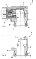
- FIG. 1, 2 show angle plug connector 1 according to the invention with a plug part 2, which has a received in a plug housing 3 contact carrier 4.
- the angle connector 1 also has a housing flange 5, which engages over a housing flange 6 of the connector housing 3 outside.
- the connector housing 3 is rotatably mounted by means of the housing flange 6. The attachment of the plug housing 3 and the housing flange 6, for example, via a clamping ring, not shown in the drawing.
- an elastic sleeve 7 is arranged on the end face via which the connector housing 3 is supported on the housing flange 5.
- the sleeve 7 engages against the housing flange 5 against rotation to this are, as from FIG. 5 can be seen, provided on the housing flange 5 associated end face of the sleeve 7 teeth 8, which engage with a sprocket 9 of the housing flange 5 with play.
- the teeth 8 may extend longitudinally and / or transversely to a virtual longitudinal axis of the sleeve 7. In the illustrated embodiment, the teeth 8 are bent by 90 degrees.
- the sleeve 7 is rotatably received in an end-side annular recess 10 of the plug housing 3.
- the recess 10 is provided on the housing flange 6 opposite the sprocket 9 of the housing flange 5. It is in the first embodiment, shown in the FIGS. 1 . 3 , as an annular groove and in the second, in the Figures 2 . 4 illustrated embodiment, designed as an annular step.
- the housing flange 6 associated end face of the sleeve 7 is flat and frontally on an annular surface of the recess 10 in abutment.
- the housing flange box 6 and the housing flange 5 in the axial and radial directions are partially connected directly form-fitting manner.
- the Sleeve 7 In the circumferential direction of the housing flange 6, the Sleeve 7 a non-positive connection between the housing flange 6 and the housing flange 5 ago.
- the sleeve 7 is under bias to associated peripheral surfaces of the housing flange 6 and the housing flange 5 wavy deformed. The deformation takes place by radially offset at the circumferential surfaces in the circumferential direction to each other arranged cam 11. As out FIG.
- the sleeve 7 is rotatably received in an annular recess 10 of the housing flange 6, rotatably and engages the housing flange 6 cross-housing flange 5 against rotation.
- the housing flange 6 can engage over the housing flange 5.
Landscapes
- Details Of Connecting Devices For Male And Female Coupling (AREA)
- Connector Housings Or Holding Contact Members (AREA)
Abstract
Description
- Die Erfindung betrifft einen Winkelsteckverbinder zum Anbau an ein Aggregatgehäuse, mit einem Steckergehäuse und einem dieses teilweise übergreifenden Gehäuseflansch, der drehsicher an dem Aggregatgehäuse befestigbar ist, wobei das Steckergehäuse drehbar an dem Gehäuseflansch befestigt und zur Festlegung der Abgangsrichtung gegenüber dem Gehäuseflansch mit Drehwiderstand verdrehbar ist.
- Derartige Winkelsteckverbinder werden beispielsweise zum Anschluss von Motoren eingesetzt. Dabei sollen die Winkelsteckverbinder leicht montierbar und in ihrer Abgangsrichtung einstellbar sein, wobei eine einmal eingestellte Abgangsrichtung sich unter der Einwirkung von Vibrationen, wie sie bei angetriebenen maschinellen Einrichtungen meist unvermeidlich sind, nicht unbeabsichtigt und selbstständig verändern kann. Somit darf die Einstellung der Abgangsrichtung nicht ohne Einwirkung eines gewissen Drehmoments möglich sein, damit das Steckergehäuse, das die Abgangsrichtung des Winkelsteckverbinders bestimmt, nach dem Einstellen in seiner Lage gegenüber dem Gehäuseflansch verbleibt.
- Aus der
DE 298 13 455 U1 ist ein Winkelstecker gemäß dem Oberbegriff bekannt, bei dem eine Rasteinrichtung zur gegenseitigen Festlegung eines Steckergehäuses und eines Gehäuseflansches in einer auswählbaren Verdrehstellung vorgesehen sind. Die Rasteinrichtung ist im Bereich einer gegenseitigen Überdeckung des Steckergehäuses und des Gehäuseflansches angeordnet, wobei die Verastung dort durch mindestens zwei ebene, aneinander anliegende Flächen zwischen den zu verrastenden Teilen und der Rasteinrichtung derart erfolgt, dass einer Anzahl am Außenumfang des Gehäuseflansches starr angeordnete Flächen eine entsprechende Anzahl unter Federlast radial beweglicher Flächen am Innenumfang des Steckergehäuses zusammen wirken. Die gegen Federlast beweglichen Flächen werden von Blattfederabschnitten gebildet, die, als Einzelteile oder als Verbund ausgebildet, vom Steckergehäuse getragen werden. - Bei den Blattfederabschnitten des vorangehend beschriebenen Gebrauchsmusters handelt es sich um filigrane Teile, die aufwendig herstellbar und schwierig; handhabbar sind, was einerseits einen unverhältnismäßig hohen Herstellungsaufwand erfordert und andererseits einen nicht unbeträchtliche Erschwerung im Zusammenbau des Winkelsteckverbinders mit sich bringt.
- Ausgenehd von diesem Stand der Technik liegt der Erfindung die Aufgabe zugrunde, einen in seiner Abgangsrichtung einstellbaren Winkelsteckverbinder vorzuschlagen, der mit einem geringst möglichen Aufwand herstellbar ist und der ohne zur Hilfenahme von Werkzeugen in nahezu jeder beliebigen Abgangsrichtung einstellbar und zugleich gegen ein unbeabsichtigtes Verstellen hinreichend gesichert ist.
- Ferner sei auf die
EP 1 465 293 A2 verwiesen, die ebenfalls die Merkmale des Oberbegriffs von Anspruch 1 offenbart. - Diese Aufgabe wird erfindungsgemäß durch einen Winkelsteckverbinder mit den Merkmalen des Anspruchs 1 gelöst. Weitere vorteilhafte Ausgestaltungen sind den Unteransprüchen zu entnehmen.
- Bei dem erfindungsgemäßen Winkelsteckverbinder ist das Steckergehäuse über eine elastische Hülse, die in einer stirnseitigen ringförmigen Ausnehmung des Steckergehäuses oder des Gehäuseflansches drehbar aufgenommen ist und die an dem jeweils zugeordneten Gehäuseflansch bzw. Steckergehäuse drehfest angreift, drehbar an dem Gehäuseflansch befestigt ist. Dabei ist im Bereich des gegenseitigen Übergriffes von dem Steckergehäuse und dem Gehäuseflansch das Steckergehäuse und der Gehäuseflansch in axialer und radialer Richtung zumindest abschnittsweise formschlüssig und in Umfangsrichtung mittels der Hülse kraftschlüssig miteinander verbunden. Die Hülse weist insbesondere eine zylindrische, an den Durchmesser des Steckergehäuses und an die Länge des Gehäuseflansches angepasste Form auf und kann aus Stahl, Kunststoff oder anderen, für Federelemente geeigneten Materialien hergestellt sein.
- Die zumindest Abschnittsweise axiale und radiale formschlüssige Verbindung des Steckergehäuses zu dem Gehäuseflansch entsteht durch das Ineinandergreifen der beiden Teile mit geringem axialen und oder radialen Spiel, wobei das Steckergehäuse in dem Gehäuseflansch drehbar festgelegt ist. In radialer Richtung sind Umfangsflächen des Gehäuseflansches und des Steckergehäuses in Anlage aneinander. Zur drehbaren Festlegung in axilaer Richtung sind an dem Steckergehäuse und dem Gehäuseflansch miteinander wirkende Sicherungsmitel vorgesehen, beispielsweise in Form eines radial ausladenden, einer Gegenfläche zugeordneten Kragens und/oder sich radial erstreckender, vorzugsweise federnd ausgebildeter Vorsprünge, die mit einer oder mehreren Nutausnehmungen im formschlüssigen Eingriff stehen. Somit kann sich das Steckergehäuse nicht ungewollt von dem Gehäuseflansch lösen.
- In Umfangsrichtung ist das Steckergehäuse über die elastische Hülse kraftschlüssig mit dem Gehäuseflansch verbunden. Die Hülse ist zwischen dem Steckergehäuse und dem Gehäuseflansch angeordnet und drehfest mit dem Gehäuseflansch oder dem Steckergehäuse im Eingriff. Sie wird von dem Steckergehäuse bzw. dem Gehäuseflansch, in dem sie drehbar in einer ringförmigen Ausnehmung aufgenommen ist, über einen Teil Ihrer Innen- und/oder Außenmantelfläche und/oder der zugeordneten Stirnfläche beaufschlagt und hemmt das Steckergehäuse beim Drehen des Steckergehäuses gegenüber dem Gehäuseflansch durch Reibung.
- Die Hülse wird beim Einstellen der Abgangsrichtung des Winkelsteckverbinders in axialer und/oder radialer Richtung reversibel elastisch verformt. Durch die Form der stirnseitigen ringförmigen Ausnehmung des Steckergehäuses oder des Gehäuseflansches, in dem die elastische Hülse drehbar eingreift, kann der Drehwiderstand gleichmäßig über den gesamten Umfang des Gehäuseflansches oder bereichsweise eingestellt werden. Zudem kann der Drehwiderstand auch durch die Geometrie der Hülse und durch Auswahl geeigneter Materialien für die Hülse beeinflusst werden.
- Vorteilhafterweise liegt die elastische Hülse in der ringförmigen Ausnehmung, die als stirnseitige Ringnut oder als stirnseitige Ringstufe ausgebildet sein kann, radial wellenförmigen verformt und unter Vorspannung ein. Zur Vorspannung sind an der Ausnehmung an mindestens einer Umfangsfläche mehrere insbesondere in Umfangsrichtung zueinander versetzt angeordnete Nocken vorgesehen, die auf die Hülse verformend einwirken. Dabei wird die Anzahl der Wellen der Hülse von der Anzahl der Nocken der Umfangsfläche bestimmt. Abhängig von der Höhe der Nocken gegenüber der Umfangsfläche, dem Abstand der Nocken zueinander und deren Anordnung an einer oder zwei Umfangsflächen der ringförmigen Ausnehmung variiert der Drehwiderstand des Winkelsteckverbinders.
- Vorzugsweise ist die Hülse während der Drehbewegung des Steckergehäuses gegenüber dem Steckerflansch in radialer Richtung dynamisch elastisch verformbar. Dabei wird die elastische Hülse beim Drehen des Steckergehäuses des Winkelsteckverbinders entlang ihren Umfang, in Drehrichtung des Steckergehäuses sich bewegend, dynamisch in radialer Richtung verformt, wobei eine tangential zur Hülse wirkende Reibungskraft zu überwinden ist.
- In einer bevorzugten Ausführungsform der Erfindung ist die Hülse in dem Gehäuseflansch oder dem Steckergehäuse, an dem die Hülse drehfest angreift, mit radialem Spiel gelagert. Damit kann sich die Hülse über ihre gesamte Länge gleichmäßig verformen, wenn sie beim Drehen des Steckergehäuses gegenüber dem Gehäuseflansch abschnittsweise dynamisch radial ausgelenkt wird, so dass die Verformung problemlos wellenförmig entlang dem Umfang der Hülse fortschreiten kann..
- In einer vorteilhaften Ausgestaltung des erfindungsgemäßen Winkelsteckverbinders ist die Hülse aus einem Kunststoffmaterial hergestellt. Zur Herstellung können alle dem Fachmann bekannten Gieß- und Tiefziehverfahren Anwendung finden. Dies ermöglicht geringe Materialkosten und eine kostengünstige Herstellung für eine Serienfertigung.
- In einer Ausführungsform ist die Hülse beschichtet. Die Beschichtung dient insbesondere der Reibungsminimierung und kann mit allen zur Oberflächenbeschichtung geeigneten, industrieüblichen Verfahren aufgebracht werden.
- Nachfolgend wird die Erfindung anhand eines in der Zeichnung dargestellten Ausführungsbeispiels näher erläutert. Weitere Merkmale der Erfindung ergeben sich aus der folgenden Beschreibung des Ausführungsbeispiels der Erfindung in Verbindung mit den Ansprüchen und der beigefügten. Zeichnung. Die einzelnen Merkmale können für sich allein oder zu mehreren bei unterschiedlichen Ausführungsformen der erfindung verwirklicht sein. Es zeigen:
- Figur 1
- eine Längsschnittdarstellung durch einen ersten erfindungsgemäßen Winkelsteckverbinder, mit einem in einem Steckergehäuse aufgenommenen Kontaktträger und mit einem Gehäuseflansch, der eine Gehäuseflanschdose übergreift;
- Figur 2
- eine Längsschnittdarstellung durch einen zweiten erfindungsgemäßen Winkelsteckverbinder;
- Figur 3
- eine Querschnittsdarstellung durch den Winkelsteckverbinder aus
Figur 1 im Bereich der Gehäuseflanschdose; - Figur 4
- eine Querschnittsdarstellung durch den Winkelsteckerbinder aus
Figur 2 im Bereich der Gehäuseflanschdose; und - Figur 5
- eine perspektivische Schnittdarstellung durch den Gehäuseflansch mit aufgesetzter Hülse gemäß
Figur 1, 2 . -
Figur 1, 2 zeigen erfindungsgemäße Winkelsteckerbinder 1 mit einem Steckerteil 2, das einen in einem Steckergehäuse 3 aufgenommenen Kontaktträger 4 aufweist. Der Winkelsteckverbinder 1 weist außerdem einen Gehäuseflansch 5 auf, der eine Gehäuseflanschdose 6 des Steckergehäuses 3 außen übergreift. An dem Gehäuseflansch 5 ist das Steckergehäuse 3 mittels der Gehäuseflanschdose 6 drehbar befestigt. Die Befestigung des Steckergehäuses 3 bzw. des Gehäuseflansches 6 erfolgt beispielsweise über einen in der Zeichnung nicht dargestellten Spannring. - Zwischen dem Gehäuseflansch 5 und der Gehäuseflanschdose 6 ist stirnseitig eine elastische Hülse 7 angeordnet über die sich das Steckergehäuse 3 an dem Gehäuseflansch 5 abstützt. Die Hülse 7 greift an dem Gehäuseflansch 5 drehfest an Dazu sind, wie aus der
Figur 5 ersichtlich, an der dem Gehäuseflansch 5 zugeordneten Stirnseite der Hülse 7 Zähne 8 vorgesehen, die in einen Zahnkranz 9 des Gehäuseflansches 5 mit Spiel eingreifen. Die Zähne 8 können sich längs und/oder quer zur einer virtuellen Längsachse der Hülse 7 erstrecken. In dem dargestellten Ausführungsbeispiel sind die Zähne 8 um 90 Grad gebogen. Sie treten in Längsrichtung der Hülse 7 aus der Hülse 7 hervor und verlaufen vor der Biegestelle in axialer und nach der Biegestelle in radialer Richtung der Hülse 7 und des Gehäuseflansches 5. - Die Hülse 7 ist in einer stirnseitigen ringförmigen Ausnehmung 10 des Steckergehäuses 3 drehbar aufgenommen. Die Ausnehmung 10 ist an der Gehäuseflanschdose 6 gegenüberliegend dem Zahnkranz 9 des Gehäuseflansches 5 vorgesehen. Sie ist in dem ersten Ausführungsbeispiel, dargestellt in den
Figuren 1 ,3 , als Ringnut und in dem zweiten, in denFiguren 2 ,4 dargestellten Ausführungsbeispiel, als Ringstufe ausgebildet. Dabei ist die der Gehäuseflanschdose 6 zugeordnete Stirnseite der Hülse 7 eben ausgebildet und stirnseitig an einer Ringfläche der Ausnehmung 10 in Anlage. - Im Bereich Ihres Übergriffes sind die Gehäuseflanschdose 6 und der Gehäuseflansch 5 in axialer und radialer Richtung bereichsweise direkt formschlüssig miteinander verbunden. In Umfangsrichtung der Gehäuseflanschdose 6 stellt die Hülse 7 eine kraftschlüssige Verbindung zwischen der Gehäuseflanschdose 6 und dem Gehäuseflansch 5 her. Dazu liegt die Hülse 7 unter Vorspannung an zugeordneten Umfangsflächen der Gehäuseflanschdose 6 und dem Gehäuseflansch 5 wellenförmig verformt an. Die Verformung erfolgt durch radial an den Umfangsflächen in Umfangsrichtung versetzt zueinander angeordneten Nocken 11. Wie aus
Figur 3, 4 entnehmbar, beaufschlagen die Nocken 11 in der Ausführung, bei der die Ausnehmung 10 als Ringstufe ausgeführt ist, nur eine Innenmantelfläche 12 der Hülse 7, und wirken in der Ausführung mit der Ringnut, auf die Innenmantelfläche 12 und eine Außenmantelfläche 13 der Hülse 7 ein. Durch die Nocken 11 wird die Hülse 7 in radialer Richtung elastisch verformt, so dass die Hülse 7 in Umfangsrichtung verlaufende Wellen aufweist und in radialer Richtung an den Gehäuseflansch 5 angepresst ist. - Bei den in der Zeichnung dargestellten Ausführungsbeispielen ist die Hülse 7 drehbar in einer ringförmigen Ausnehmung 10 der Gehäuseflanschdose 6, drehbar aufgenommen und greift an dem die Gehäuseflanschdose 6 übergreifenden Gehäuseflansch 5 drehfest an. Prinzipiell ist es auch möglich, die Hülse 7 drehbar im Gehäuseflansch 5 aufzunehmen und an der Gehäuseflanschdose 6 drehfest angreifen zu lassen. Des Weiteren kann abweichend von den Ausführungsbeispielen die Gehäuseflanschdose 6 den Gehäuseflansch 5 übergreifen.
Claims (6)
- Winkelsteckverbinder (1) zum Anbau an ein Aggregatgehäuse, mit einem Steckergehäuse (3) und einem dieses teilweise übergreifenden Gehäuseflansch (5), der drehsicher an dem Aggregatgehäuse befestigbar ist, wobei das Steckergehäuse (3) an dem Gehäuseflansch (5) drehbar befestigt und zur Festlegung der Abgangsrichtung gegenüber dem Gehäuseflansch (5) mit Drehwiderstand verdrehbar ist, dadurch gekennzeichnet, dass das Steckergehäuse (3) über eine elastische Hülse (7), die in einer stirnseitigen ringförmigen Ausnehmung (10) des Steckergehäuses (3) oder des Gehäuseflansches (5) drehbar aufgenommen ist und an dem jeweils zugeordneten Gehäuseflansch (5) bzw. Steckergehäuse (3) drehfest angreift, drehbar befestigt ist, wobei das Steckergehäuse (3) und der Gehäuseflansch (5) im Bereich ihres Übergriffes in axialer und radialer Richtung zumindest abschnittsweise formschlüssig und in Umfangsrichtung mittels der Hülse (7) kraftschlüssig miteinander verbunden sind.
- Winkelsteckverbinder nach Anspruch 1, dadurch gekennzeichnet, dass die Hülse (7) in der Ausnehmung (10) radial wellenförmig verformt einliegt und die Ausnehmung (10) an mindestens einer Umfangsfläche versetzt zueinander angeordnete Nocken (11) aufweist, die auf die Hülse (7) verformend einwirken.
- Winkelsteckverbinder nach Anspruch 1 oder 2, dadurch gekennzeichnet, dass die Hülse (7) während der Drehbewegung des Steckergehäuses (3) gegenüber dem Gehäuseflansch (5) in radialer Richtung dynamisch elastisch verformbar ist.
- Winkelsteckverbinder nach einem der vorangegangenen Ansprüche, dadurch gekennzeichnet, dass die Hülse (7) in dem Gehäuseflansch (5) oder dem Steckergehäuse (3), an dem die Hülse (7) drehfest angreift, mit radialem Spiel gelagert ist.
- Winkelsteckverbinder nach einem der vorangegangenen Ansprüche, dadurch gekennzeichnet, dass die Hülse (7) aus einem Kunststoffmaterial hergestellt ist.
- Winkelsteckverbinder nach einem der vorangegangenen Ansprüche, dadurch gekennzeichnet, dass die Hülse (7) beschichtet ist.
Applications Claiming Priority (2)
| Application Number | Priority Date | Filing Date | Title |
|---|---|---|---|
| DE202007001523U DE202007001523U1 (de) | 2007-02-02 | 2007-02-02 | Winkelsteckverbinder mit veränderbarer Abgangsrichtung |
| PCT/DE2008/000196 WO2008092444A2 (de) | 2007-02-02 | 2008-02-04 | Winkelsteckverbinder mit veränderbarer abgangsrichtung |
Publications (2)
| Publication Number | Publication Date |
|---|---|
| EP2115822A2 EP2115822A2 (de) | 2009-11-11 |
| EP2115822B1 true EP2115822B1 (de) | 2012-05-30 |
Family
ID=38136156
Family Applications (1)
| Application Number | Title | Priority Date | Filing Date |
|---|---|---|---|
| EP08706861A Ceased EP2115822B1 (de) | 2007-02-02 | 2008-02-04 | Winkelsteckverbinder mit veränderbarer abgangsrichtung |
Country Status (5)
| Country | Link |
|---|---|
| US (1) | US7901245B2 (de) |
| EP (1) | EP2115822B1 (de) |
| JP (1) | JP4740370B2 (de) |
| DE (2) | DE202007001523U1 (de) |
| WO (1) | WO2008092444A2 (de) |
Cited By (1)
| Publication number | Priority date | Publication date | Assignee | Title |
|---|---|---|---|---|
| BE1032139A1 (de) | 2023-11-13 | 2025-06-06 | Phoenix Contact Gmbh & Co | Steckverbinder, System aus einem Steckverbinder und einem Kabel und System aus einem Steckverbinder und einer Steckverbinderaufnahme |
Families Citing this family (10)
| Publication number | Priority date | Publication date | Assignee | Title |
|---|---|---|---|---|
| DE102008046235B3 (de) * | 2008-09-08 | 2010-04-15 | Fct Electronic Gmbh | Miniaturisierter Hochstromstecker |
| DE102013007069A1 (de) * | 2013-04-23 | 2014-10-23 | Hypertac Gmbh | Steckerträger zum Montieren an ein Maschinengehäuse |
| DE202013011743U1 (de) * | 2013-04-25 | 2014-07-17 | Amphenol-Tuchel Electronics Gmbh | Hochstromstecker |
| DE202013012278U1 (de) | 2013-12-20 | 2016-01-11 | Phoenix Contact Connector Technology Gmbh | Winkelsteckverbinder mit einstellbarer Abgangsrichtung |
| DE202015102170U1 (de) * | 2015-04-30 | 2015-05-13 | Intercontec Pfeiffer Industrie-Steckverbindungen Gmbh | Elektrischer Winkelstecker mit Stützring und Verrastring einer Gegenlagerung für ein Federelement |
| DE102016001466A1 (de) * | 2016-02-09 | 2017-08-10 | Yamaichi Electronics Deutschland Gmbh | Gewinkelter Steckverbinder und Verfahren zum Assemblieren |
| DE102017104982B3 (de) * | 2017-03-09 | 2018-08-02 | Te Connectivity Industrial Gmbh | Elektrischer Stecker mit spezifischer Erdung von Außenteilen |
| WO2019193212A1 (en) * | 2018-04-06 | 2019-10-10 | Drägerwerk AG & Co. KGaA | Modular patient monitoring medical device and connector |
| CN116131011A (zh) * | 2022-12-30 | 2023-05-16 | 中航光电华亿(沈阳)电子科技有限公司 | 一种直角插头及连接器 |
| CN117039562A (zh) * | 2023-06-27 | 2023-11-10 | 中航光电科技股份有限公司 | 一种新型可调角度结构的连接器 |
Family Cites Families (15)
| Publication number | Priority date | Publication date | Assignee | Title |
|---|---|---|---|---|
| JPS5861991A (ja) * | 1981-10-09 | 1983-04-13 | Agency Of Ind Science & Technol | レ−ザ溶接方法及び装置 |
| JPS6180585A (ja) * | 1984-09-26 | 1986-04-24 | Nec Corp | 磁気バブルメモリ素子 |
| JPS61139582A (ja) * | 1984-12-11 | 1986-06-26 | Mitsubishi Heavy Ind Ltd | 低速肥形船の船首形状 |
| EP0189343A3 (de) * | 1985-01-22 | 1988-11-30 | Itt Industries, Inc. | Verbinder mit Radialkraft zum Verhindern des Entkuppelns |
| CA1296079C (en) * | 1986-03-06 | 1992-02-18 | Mitsuru Takeda | Locked connector |
| JPS6383775A (ja) * | 1986-09-29 | 1988-04-14 | Matsushita Electric Ind Co Ltd | 複写機 |
| US4726782A (en) * | 1987-01-05 | 1988-02-23 | G & H Technology, Inc. | Anti-decoupling device for an electrical connector |
| US4820184A (en) * | 1987-10-05 | 1989-04-11 | Interconnection Products Incorporated | Electrical connector retaining ratchet |
| FR2642908B1 (fr) * | 1989-02-03 | 1992-09-04 | Drogo Pierre | Connecteur electrique |
| JPH0346972A (ja) * | 1989-07-11 | 1991-02-28 | Ricoh Co Ltd | 両面記録装置 |
| DE29509249U1 (de) * | 1994-12-01 | 1996-03-28 | Interconnectron Gesellschaft für industrielle Steckverbindungen mbH, 94469 Deggendorf | Winkelförmiger Steckträger |
| JPH11102765A (ja) * | 1997-09-25 | 1999-04-13 | Nec Corp | ロータリコネクタ |
| DE29813455U1 (de) | 1998-07-28 | 1999-12-02 | Interconnectron GmbH, 94469 Deggendorf | Winkelförmiger Steckerträger |
| DE10314914B3 (de) * | 2003-04-01 | 2004-10-07 | Coninvers Elektrotechnische Bauelemente Gmbh | Winkelsteckverbinder |
| US7625226B1 (en) * | 2008-12-02 | 2009-12-01 | Itt Manufacturing Enterprises, Inc. | Radial anti-rotation coupling |
-
2007
- 2007-02-02 DE DE202007001523U patent/DE202007001523U1/de not_active Expired - Lifetime
-
2008
- 2008-02-04 EP EP08706861A patent/EP2115822B1/de not_active Ceased
- 2008-02-04 WO PCT/DE2008/000196 patent/WO2008092444A2/de not_active Ceased
- 2008-02-04 US US12/375,698 patent/US7901245B2/en not_active Expired - Fee Related
- 2008-02-04 DE DE112008000883T patent/DE112008000883A5/de not_active Withdrawn
- 2008-02-04 JP JP2009508131A patent/JP4740370B2/ja not_active Expired - Fee Related
Cited By (1)
| Publication number | Priority date | Publication date | Assignee | Title |
|---|---|---|---|---|
| BE1032139A1 (de) | 2023-11-13 | 2025-06-06 | Phoenix Contact Gmbh & Co | Steckverbinder, System aus einem Steckverbinder und einem Kabel und System aus einem Steckverbinder und einer Steckverbinderaufnahme |
Also Published As
| Publication number | Publication date |
|---|---|
| US20090305558A1 (en) | 2009-12-10 |
| WO2008092444A2 (de) | 2008-08-07 |
| DE202007001523U1 (de) | 2007-05-31 |
| WO2008092444A3 (de) | 2008-11-13 |
| EP2115822A2 (de) | 2009-11-11 |
| JP2009535768A (ja) | 2009-10-01 |
| JP4740370B2 (ja) | 2011-08-03 |
| DE112008000883A5 (de) | 2010-01-07 |
| US7901245B2 (en) | 2011-03-08 |
Similar Documents
| Publication | Publication Date | Title |
|---|---|---|
| WO2008092444A2 (de) | Winkelsteckverbinder mit veränderbarer abgangsrichtung | |
| EP2318723B1 (de) | Befestigungsanordnung mit toleranzausgleich | |
| DE102009011462B4 (de) | Beschlag für einen Fahrzeugsitz und Fahrzeugsitz | |
| DE10144840B4 (de) | Beschlag für einen Fahrzeugsitz | |
| DE102006037218B4 (de) | Rastgelenk und Außenspiegel mit einem solchen Rastgelenk | |
| DE102014201742A1 (de) | Stellantrieb für ein kraftfahrzeug, insbesondere für einen kraftfahrzeugsitz | |
| DE102009040504A1 (de) | Beschlag für einen Fahrzeugsitz | |
| DE102013000850B4 (de) | Kupplungsanordnung zur kraftschlüssigen Verbindung einer Welle mit der Kupplungsanordnung | |
| WO2018202434A1 (de) | Verstelleinheit und einstellverfahren für ein bauteil | |
| DE102009035831A1 (de) | Baueinheit | |
| DE202013012278U1 (de) | Winkelsteckverbinder mit einstellbarer Abgangsrichtung | |
| EP3516242B1 (de) | Toleranzausgleichselement | |
| DE102006010270B4 (de) | Zahnradanordnung | |
| WO2014015859A1 (de) | Bohrfutter | |
| EP1465293A2 (de) | Winkelsteckverbinder | |
| DE29509249U1 (de) | Winkelförmiger Steckträger | |
| WO2011128043A2 (de) | Sitzverstellvorrichtung | |
| DE10144143C1 (de) | Torsionsmodul für eine Drehmomenterfassungseinrichtung | |
| EP2887463B1 (de) | Winkelsteckverbinder mit einstellbarer Abgangsrichtung | |
| EP1869333B1 (de) | Lagerbuchse | |
| WO2000008284A1 (de) | Anschlusseinrichtung zur verbindung eines türfeststellers mit einem kraftwagentürscharnier | |
| DE19548609C2 (de) | Zahnradgetriebe | |
| DE102004044753B4 (de) | Neigungsverstellbeschlag für die Rückenlehne eines Kraftfahrzeugsitzes | |
| EP1002593B1 (de) | Verfahren zum Herstellen einer Nabe durch Stanzen | |
| EP2893110B1 (de) | Anschlaganordnung für ein lageveränderbares element an einer fahrzeugkarosserie |
Legal Events
| Date | Code | Title | Description |
|---|---|---|---|
| PUAI | Public reference made under article 153(3) epc to a published international application that has entered the european phase |
Free format text: ORIGINAL CODE: 0009012 |
|
| 17P | Request for examination filed |
Effective date: 20080922 |
|
| AK | Designated contracting states |
Kind code of ref document: A2 Designated state(s): AT BE BG CH CY CZ DE DK EE ES FI FR GB GR HR HU IE IS IT LI LT LU LV MC MT NL NO PL PT RO SE SI SK TR |
|
| DAX | Request for extension of the european patent (deleted) | ||
| GRAP | Despatch of communication of intention to grant a patent |
Free format text: ORIGINAL CODE: EPIDOSNIGR1 |
|
| RBV | Designated contracting states (corrected) |
Designated state(s): DE IT |
|
| GRAS | Grant fee paid |
Free format text: ORIGINAL CODE: EPIDOSNIGR3 |
|
| GRAA | (expected) grant |
Free format text: ORIGINAL CODE: 0009210 |
|
| AK | Designated contracting states |
Kind code of ref document: B1 Designated state(s): DE IT |
|
| REG | Reference to a national code |
Ref country code: DE Ref legal event code: R096 Ref document number: 502008007312 Country of ref document: DE Effective date: 20120726 |
|
| PLBE | No opposition filed within time limit |
Free format text: ORIGINAL CODE: 0009261 |
|
| STAA | Information on the status of an ep patent application or granted ep patent |
Free format text: STATUS: NO OPPOSITION FILED WITHIN TIME LIMIT |
|
| 26N | No opposition filed |
Effective date: 20130301 |
|
| REG | Reference to a national code |
Ref country code: DE Ref legal event code: R097 Ref document number: 502008007312 Country of ref document: DE Effective date: 20130301 |
|
| REG | Reference to a national code |
Ref country code: DE Ref legal event code: R082 Ref document number: 502008007312 Country of ref document: DE Representative=s name: ABACUS PATENTANWAELTE, DE |
|
| PGFP | Annual fee paid to national office [announced via postgrant information from national office to epo] |
Ref country code: DE Payment date: 20160711 Year of fee payment: 9 Ref country code: IT Payment date: 20160729 Year of fee payment: 9 |
|
| REG | Reference to a national code |
Ref country code: DE Ref legal event code: R119 Ref document number: 502008007312 Country of ref document: DE |
|
| PG25 | Lapsed in a contracting state [announced via postgrant information from national office to epo] |
Ref country code: DE Free format text: LAPSE BECAUSE OF NON-PAYMENT OF DUE FEES Effective date: 20170901 |
|
| PG25 | Lapsed in a contracting state [announced via postgrant information from national office to epo] |
Ref country code: IT Free format text: LAPSE BECAUSE OF NON-PAYMENT OF DUE FEES Effective date: 20170204 |