EP2115439B1 - Röntgenfluoreszenz-analysegerät mit kleinem spot - Google Patents
Röntgenfluoreszenz-analysegerät mit kleinem spot Download PDFInfo
- Publication number
- EP2115439B1 EP2115439B1 EP08729626.5A EP08729626A EP2115439B1 EP 2115439 B1 EP2115439 B1 EP 2115439B1 EP 08729626 A EP08729626 A EP 08729626A EP 2115439 B1 EP2115439 B1 EP 2115439B1
- Authority
- EP
- European Patent Office
- Prior art keywords
- sample
- detector
- spot
- analyzer
- shutter
- Prior art date
- Legal status (The legal status is an assumption and is not a legal conclusion. Google has not performed a legal analysis and makes no representation as to the accuracy of the status listed.)
- Active
Links
Images












Classifications
-
- G—PHYSICS
- G01—MEASURING; TESTING
- G01N—INVESTIGATING OR ANALYSING MATERIALS BY DETERMINING THEIR CHEMICAL OR PHYSICAL PROPERTIES
- G01N23/00—Investigating or analysing materials by the use of wave or particle radiation, e.g. X-rays or neutrons, not covered by groups G01N3/00 – G01N17/00, G01N21/00 or G01N22/00
- G01N23/22—Investigating or analysing materials by the use of wave or particle radiation, e.g. X-rays or neutrons, not covered by groups G01N3/00 – G01N17/00, G01N21/00 or G01N22/00 by measuring secondary emission from the material
- G01N23/223—Investigating or analysing materials by the use of wave or particle radiation, e.g. X-rays or neutrons, not covered by groups G01N3/00 – G01N17/00, G01N21/00 or G01N22/00 by measuring secondary emission from the material by irradiating the sample with X-rays or gamma-rays and by measuring X-ray fluorescence
-
- G—PHYSICS
- G01—MEASURING; TESTING
- G01N—INVESTIGATING OR ANALYSING MATERIALS BY DETERMINING THEIR CHEMICAL OR PHYSICAL PROPERTIES
- G01N2223/00—Investigating materials by wave or particle radiation
- G01N2223/07—Investigating materials by wave or particle radiation secondary emission
- G01N2223/076—X-ray fluorescence
Definitions
- the present invention relates to hand-held x-ray fluorescence analyzers and, more particularly, to such analyzers that illuminate a small spot on a sample with x-rays.
- Analyzing chemical composition of samples is important in many contexts, including identifying and segregating metal types in metal recycling facilities, quality control testing in factories and forensic work.
- Several analytical methods are available.
- One common analysis method employs x-ray fluorescence (XRF). When exposed to high energy primary x-rays from a source, each atomic element present in a sample produces a unique set of characteristic fluorescence x-rays that are essentially a fingerprint for the specific element.
- An x-ray fluorescence analyzer determines the chemistry of a sample by illuminating a spot on the sample with x-rays and measuring the spectrum of characteristic x-rays emitted by the different elements in the sample.
- the primary source of x-rays may be an x-ray tube or a radioactive material, such as a radioisotope.
- x-rays includes photons of energy between about 1 keV and about 150 keV and will, therefore, include: the characteristic x-rays emitted by an excited atom when it deexcites; bremsstrahlung x-rays emitted when an electron is scattered by an atom; elastic and inelastically scattered photons generally referred to as Rayleigh and Compton scattered radiation, respectively; and gamma rays in this energy range emitted when an excited nucleus deexcites.
- a characteristic fluorescent x-ray is created when a photon of sufficient energy strikes an atom in the sample, dislodging an electron from one of the atom's inner orbital shells. The atom then nearly instantaneously regains stability, filling the vacancy left in the inner orbital shell with an electron from one of the atom's higher energy (outer) orbital shells. Excess energy may be released in the form of a fluorescent x-ray, of an energy characterizing the difference between two quantum states of the atom.
- XRF analyzers By inducing and measuring a wide range of different characteristic fluorescent x-rays emitted by the different elements in the sample, XRF analyzers are able to determine the elements present in the sample, as well as to calculate their relative concentrations based on the number of fluorescent x-rays occurring at specific energies.
- an XRF analyzer can also identify the sample by name, by referencing a programmed table or library of known materials.
- the size of the x-ray spot on the sample determines how much of a sample is analyzed.
- a small x-ray spot would be desirable.
- a user who analyzes small components and solder joints on printed circuit boards (such as in recycling facilities) would benefit from using a hand-held XRF analyzer that produces a very small spot, so a component or solder joint of interest could be analyzed without the fluorescing x-rays illuminating surrounding components and, therefore, confusing the chemical composition of the item under test with the chemical compositions of surrounding materials.
- analyzing a series of small, spaced-apart portions of a sample would enable a user to gauge the homogeneity of the sample.
- a hand-held, self-contained, test instrument for analyzing composition of a sample in accordance with claim 1.
- the invention also extends to a hand-held, self-contained test instrument in accordance with claim 2.
- the test instrument also includes a detector collimator for the beam.
- the detector collimator has a second distal exit aperture characterized by a second transverse dimension.
- the second distal exit is disposed at a distance from the sample no greater than about twice the second transverse dimension.
- the second transverse dimension may be less than about 8 mm, about 3 mm, about 1 mm or about 0.3 mm.
- the source collimator and the detector collimator may move together between at least two positions. In the first position, the beam passes through the source collimator to illuminate the spot.
- the distal exit apertures of the two collimators may be substantially parallel to a surface of the sample that is to be analyzed. In the second position, the beam passes through the detector collimator to illuminate the spot.
- the analyzer includes a collimator for aiming a beam of penetrating radiation toward a desired location on the sample and for determining the size of the spot produced on the sample.
- the collimator includes a shutter for selectively allowing the beam to illuminate the sample or blocking the beam and, thereby, preventing illumination of the sample by the beam.
- the size of the spot may be fixed or adjustable.
- any suitable beam of penetrating radiation may be used to illuminate a spot on the surface to produce a response signal from the sample and, thereby, interrogate the elemental composition of a region of the sample.
- a hand-held XRF analyzer includes a second collimator between a sample and a detector to limit spurious fluorescent and reflected primary x-rays observed by the detector.
- the hand-held XRF analyzer may include a digital camera oriented toward the portion of the sample that is, or would be, illuminated within the perimeter of the x-ray spot.
- the camera together with a display of an image produced by the camera, facilitates aiming the analyzer, such that the x-ray beam illuminates a desired portion of the sample.
- a flattening process may be applied to the image to correct image distortion introduced by the camera's location and aim, relative to the x-ray spot.
- the analyzer includes a reticule in the displayed image to indicate the portion of the sample that is, or would be, illuminated by the x-ray beam, i.e., to indicate the size and location of the x-ray spot.
- Methods and apparatus are disclosed for calibrating the reticule, so the reticule accurately reflects the position, size and/or shape of the x-ray spot.
- the analyzer may include text or graphics that contain information about the analyzed sample. This information may include the chemical composition of the tested portion of the sample, the date and time of the testing, the user's name, notes entered by the user (such as the source of the sample) and the like.
- the image may be stored in the hand-held analyzer or provided for external storage or display. Consequently, the hand-held analyzer may produce an archive record containing both an image of the portion of the sample that is analyzed and an analysis of the tested portion of the sample.
- the image may be a still image or a video clip of the sample being analyzed.
- the image may be stored separate from, but associated with, the analysis information.
- the image or the analysis information may include a pointer (such as a uniform resource locator (URL)) or other reference to the other.
- URL uniform resource locator
- helium gas may be used to purge air from a chamber within the analyzer.
- Various mechanisms may monitor the flow rate or presence of a purge gas or presence of ambient gas (air or a constituent thereof) in the chamber and automatically adjust the flow rate of the purge gas or warn a user of the presence of ambient gas in the chamber.
- the chamber may be evacuated of a substantial amount of air otherwise present in the chamber.
- Fig. 1 is a schematic diagram of a prior-art self-contained, hand-held XRF analyzer 100 in use.
- Fig. 1 shows both a top view and a side view of the hand-held analyzer 100.
- a primary x-ray source 101 produces an x-ray beam 102 directed at the surface of the sample 104.
- the energy of the primary x-ray beam 102 causes inner-shell electrons (shown enlarged in Fig. 1 ) to be ejected from their orbits in individual atoms of the sample 104.
- an electron 106 is ejected from an inner (lower energy) shell, as indicated by an arrow 108.
- a vacancy 110 left by the ejected electron 106 is filled by an electron 112 from an outer (higher energy) shell.
- the energy difference between the two energy shells involved in the process is generally emitted in the form of x-ray radiation, i.e., a fluorescent x-ray 114.
- the energy difference is characteristic of the element from which the electron 106 is emitted. Measuring the energy and intensity of the fluorescent x-ray 114 enables the element to be identified and quantified, respectively.
- a detector 116 registers individual x-ray events and sends electrical signals to a preamplifier 118.
- the preamplifier 118 amplifies the signals from the detector 116 and sends the amplified signals to a digital signal processor (DSP) 120.
- DSP 120 collects and digitizes the x-ray events occurring over time and sends resulting spectral data to a main processor 122.
- the processor 122 mathematically analyzes the spectral data and produces a detailed composition analysis.
- the resulting composition analysis may be compared against an internal table stored in a memory 124 to determine an alloy grade or other designation for the tested sample 104. Results of the analysis are displayed on a touchscreen 126 on the top portion of the hand-held analyzer 100 and, optionally, stored in the memory 124. Buttons and other controls, such as those indicated at 128, and the touchscreen 126, enable a user to interact with the processor 122.
- a detachable rechargeable battery 126 powers the processor 122 and other electrical components within the analyze
- the prior-art analyzer 100 includes a shutter to selectively enable or prohibit the primary x-ray beam 102 from exiting the analyzer and striking the surface of the sample 104.
- Fig. 9 is a perspective view of such a prior-art shutter 900.
- the shutter includes a gear rack 902, which may be engaged by a spur gear (not shown) to translate the shutter 900 laterally (as indicated by an arrow 904) between two positions. In one position, the x-ray beam 102 passes through a first hole 906, as indicated by an arrow 908, and strikes the surface of the sample 104.
- the x-ray beam passes through a second hole 910 and interacts with a calibration sample on the back side of an angled portion 912, which produces a calibration spectrum directed toward a detector, as indicated by an arrow 914.
- the x-ray beam does not exit the analyzer 100. Instead, the x-ray beam is used to produce a calibration spectrum to calibrate the analyzer 100.
- the prior-art analyzer 100 is incapable of producing a small x-ray spot on the sample.
- illuminating a sample with a small x-ray spot would facilitate analyzing a small sample or a small portion of a sample, such as a component or a solder joint on a printed circuit board.
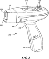
- Fig. 2 is a perspective view of a self-contained, hand-held XRF analyzer 200.
- the analyzer 200 includes: a screen 210 (such as a built-in touchscreen or non-touch-sensitive screen or an attached personal digital assistant (PDA)) for displaying analytical results and images and (optionally) receiving operator inputs; a processor and memory (not shown) for storing instructions and data and for controlling operation of the analyzer 200; operator interface buttons 212; a trigger switch 208 for initiating an analysis; and a detachable rechargeable battery 214 for powering all the electrical components of the analyzer 200.
- a screen 210 such as a built-in touchscreen or non-touch-sensitive screen or an attached personal digital assistant (PDA)
- PDA personal digital assistant
- a snout portion 202 houses a collimated shutter (not visible in Fig. 2 , but described in detail below) that enables the analyzer 200 to produce a small x-ray spot on the surface of a sample.
- a forward wall 204 of the snout 202 is pressed against a sample.
- a spring-loaded, momentary contact switch 206 on the forward wall 204 is depressed by the sample.
- the switch 206 may act as a safety interlock, preventing emission of x-rays outside the analyzer 200 unless the analyzer is pressed against a sample.
- the analyzer 200 is placed in a stand (not shown), which both holds the sample and depresses the switch 206.
- Fig. 3 is a close-up view of the snout 202, showing a collimated shutter 300 (mostly in phantom).
- the collimated shutter (300) of Fig. 3 does not embody the present invention.
- the collimated shutter 300 includes a tube 308.
- An x-ray source (shown schematically at 302) produces an x-ray beam 304 directed towards one side (the back) of the collimated shutter 300.
- the collimated shutter 300 can move laterally or rotationally between at least two positions. In the position illustrated in Fig.
- the tube 308 is aligned with the x-ray beam 304, between the x-ray source 302 and a window 310, so the x-ray beam may pass through the tube 308, exit the snout 202 via the window 310 and strike a sample (not shown).
- the end of the tube 308 from which the primary x-rays exit defines a distal exit aperture 311. Fluorescent x-rays 312 from the sample enter the window 310 and strike a detector 314 (shown in phantom).
- the window 310 may be covered by a thin sheet of x-ray transparent material, such as a polyimide film, to prevent dirt or other contaminants from entering the snout 202 through the window 310.
- a suitable polyimide film is available under the tradename Kapton from E. I. du Pont de Nemours and Company.
- Fig. 4 is a close-up view of the snout 202 showing the collimated shutter 300 in another position, i.e. moved laterally along the arrow 306.
- the tube 308 is not aligned between the x-ray source 302 and the window 310.
- the collimated shutter 300 blocks the x-ray beam 304 from exiting the window 310; thus, in this position, the collimated shutter 300 acts as a closed shutter.
- the x-ray beam 304 passes through a hole 402 and is scattered by an angled portion 400 of the collimated shutter 300. At least some of the scattered x-ray beam reaches the detector 314.
- the detector 314 may be used to calibrate the analyzer 200, with respect to such spectral parameter as the energy scale of the x-ray spectra, the energy resolution of characteristic x-rays, x-ray beam intensity, and the like.
- a calibration sample such as silver, may be placed on the back side of the angled portion 400 to produce a calibration spectrum.
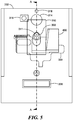
- Fig. 5 is a view of the front of the snout 202 showing the collimated shutter 300 in the same position as is shown in Fig. 3 , i.e., the position that allows the x-ray beam to exit the window 310.
- the end of the tube 308 closest to the window 310 is approximately centered (left to right) within the window 310.
- the tube 308 is displaced laterally in the window 310, possibly far enough so that the tube 308 is no longer visible through the window 310.
- Fig. 6 is a cross-sectional view of the snout 202, taken along section line A-A in Fig. 5 .
- An output portion of the primary x-ray source is indicated schematically at 600.
- This output portion 600 may be an x-ray spot produced on an anode of a miniature x-ray tube (not shown),or any other suitable source of x-rays.
- Primary filters (not shown) may be introduced between the x-ray source 600 and the collimated shutter 300 to adjust the energy versus intensity spectrum of the primary x-ray beam. If the primary x-ray source is an x-ray tube, the voltage supplied to the x-ray tube may be varied to adjust the energy of the primary x-ray beam.
- an x-ray beam passes through the tube 308 and exits the snout 202 via the window 310 to illuminate a spot on the surface 604 of the sample.
- the tube 308 defines a central bore 606, through which the x-ray beam passes.
- the distal exit aperture 311 is defined where the bore 606 exits the end 612 of the tube closest to the surface 604 of the sample.
- An infinitesimal primary x-ray spot at 600 would produce no penumbra on the surface 604, whereas a larger primary x-ray spot at 600 produces a penumbra.
- the size of the penumbra may be limited by close proximity of the distal exit aperture 311 to the surface 604.
- the size of the spot on the sample surface 604 is determined primarily by the size of the primary x-ray source spot, the geometry of the central bore 606, notably the size of the distal exit aperture 311, and the distance 610 between the distal exit aperture 311 and the surface 604.
- the size of the distal exit aperture 311 is characterized by a transverse dimension, i.e., a dimension of the bore 606 measured along a cross-section of the tube 308 taken perpendicular to the axis of the bore 606, near the end 612 of the tube 308.
- the cross-sectional shape of the bore 606 may be circular, elliptical, square or any other shape suitable for passing the x-ray beam. If the bore has a circular cross section, the dimension may be a diameter.
- the distal exit aperture 311 should be disposed at a distance from the sample no greater than twice the transverse dimension. Preferably, the distal exit aperture 311 should be disposed at a distance from the sample less than, or no greater than, the transverse dimension. If the distal exit aperture 311 and the separation distance 610 are approximately equal, the spot size is approximately equal to, or slightly larger than, the size of the distal exit aperture 311.
- the distal exit aperture 311 is disposed about 2.8 mm from the surface 604 of the sample, and the distal exit aperture 311 has a transverse dimension of about 2.8 mm, thereby producing an approximately 3 mm diameter x-ray spot on the surface 604 of the sample.
- the transverse dimension may be between about 0.3 mm and about 8 mm, and the distal exit aperture 311 may be disposed between about 0.3 mm and about 8 mm from the surface 604.
- Other transverse dimensions and displacements are also possible.
- the distance between the distal exit aperture 311 and the surface 604 of the sample may depend on the length of the tube 308, which may depend, at least in part due to mechanical strength and rigidity requirements, on the thickness of the wall of the tube 604.
- the tube wall thickness may, in turn, depend at least in part on the x-ray flux involved. That is, higher x-ray fluxes may require thicker tube walls.
- An optimal combination of distance and aperture size may be governed by flux characteristics of the source (such as the intensity (flux) of the beam generated by the source) and feature characteristics of the application (such as how small an area on the sample should be illuminated by the spot).
- the tube wall thickness may depend on both the energy of the x-rays and their intensities.
- the energy of the x-rays passing through the tube 308 depends on the voltage applied to the x-ray tube and the filtration of the x-rays.
- a telescoping collimator (not shown) or other collimator arrangements may be used to produce an adjustable-size spot on the sample within the scope of the present invention.
- the shape of the spot on the sample surface 604 is determined primarily by the geometry of the central bore 606, including the shape of the distal exit aperture 311, and the geometric relationship between the plane of the sample surface 604 and the plane of the end 612 of the tube 308. If the plane of the end 612 of the tube 308 were perpendicular to the axis of the bore 606, the projected x-ray spot would be elliptical. However, as discussed below with respect to Fig. 8 , the end 612 of the tube 308 may be shaped such that the end 612 is approximately parallel to the surface 604 of the sample. This parallel relationship reduces the eccentricity of the x-ray spot.
- an upper edge 614 of the tube 308 may prevent some of the radiation excited in the sample from reaching the detector 314. This cuts off a portion of the x-ray spot and makes the x-ray spot appear more circular, from the perspective of the detector 314. Furthermore, the detector 314 may view the surface 604 of the sample at an oblique angle, further reducing the apparent eccentricity of the x-ray spot.
- the bore 606 may have a circular cross-sectional shape to produce a circular or near-circular x-ray spot.
- the x-ray spot need not be a circle or ellipse. Any shape x-ray spot, such as square, is acceptable in particular applications.
- the detector 314 is preferably larger than the x-ray spot, and preferably as large as may be comfortably accommodated within space constraints of the housing and other components in the analyzer.
- the detector 314 may, if necessary, be cooled to reduce noise, such as "dark current.” Conventional thermoelectric or any other suitable cooling mechanism may be used.
- Figs. 7A-C contain front, bottom and back views, respectively, of the collimated shutter 300
- Fig. 8 is a cross-sectional view of the collimated shutter taken along section line B-B of Fig. 7A
- the collimated shutter 300 includes a shuttle 700, as well as the tube 308 and the angled portion 400 discussed above.
- the tube 308 is secured to the shuttle 700, such as in a bore.
- the tube 308 may be secured in the bore by press fitting the tube 308 in the bore, or by a suitable adhesive such as Loctite adhesive (available from Henkel Corp., Rocky Hill, CT), or by threading the tube 308 into the bore of the shuttle 700 or by any other suitable mechanism.
- the angled portion 400 may be formed as part of the shuttle 700, or the angled portion 400 may be attached to the shuttle 700, such as by a suitable adhesive or by welding.
- the shuttle 700, the tube 308 and angled portion 400 are preferably made of an x-ray opaque material, such as a tungsten alloy or sintered mixture. Suitable materials include tungsten alloys or mixtures that include about 90% tungsten. Such materials are available under the tradenames Hevimet and Densalloy. Lower percentages of tungsten may be used if the wall thickness of the tube 308 and thicknesses of portions of the shuttle 700 and angled portion 400 are increased sufficiently to block the x-rays. Tungsten may be alloyed with nickel, copper, chrome or other materials to improve its machinability. Other suitable materials for the collimated shutter 300 include lead, tantalum or other elements with atomic numbers, typically greater than 45.
- Steel or another material may be lined or clad with lead to produce the collimated shutter 300 or portions thereof.
- the shuttle 700, the tube 308 and angled portion 400, or portions thereof, may be machined from a solid piece of material or may be made using powder metallurgy technology.
- the shuttle 700, the tube 308 and angled portion 400, or portions thereof, may also be injection molded as one or more pieces.
- a polymer filled with tungsten or lead powder is used to injection mold the collimated shutter 300 as a single piece.
- the collimated shutter 300 defines a central bore 606 along an axis 800 that passes through the tube 308.
- the central bore 606 is stepped, i.e., the bore 606 is larger at the end 802 of the tube 308 where the x-rays enter the tube 308 than at the end 612 where the x-rays exit the tube 308.
- the shuttle 700 defines a yet larger opening 804 where the x-rays enter the shuttle 700 from the primary x-ray source. Collectively, the tube 308 and the opening 804 in the shuttle 700 form a collimator for the primary x-ray beam.
- the collimator may be stepped, as exemplified by the stepped portion of the bore through the tube 308 and by a step 806 formed by the tube 308, where it joins the shuttle 700.
- a conical, tapered or other shaped passage through the collimator is acceptable.
- the end 612 of the tube 308 is preferably approximately parallel to the surface 604 of the sample, making the distal exit aperture 311 also approximately parallel to the surface of 604 of the sample.
- an angle 808 is selected, such that the end 612 of the tube 308 is approximately parallel to the surface 604 of the sample.
- the larger opening 804 at the x-ray source end of the collimator allows for some imprecision in the size or location of the x-ray emitting spot on the x-ray tube anode or other primary x-ray source.
- the proximity i.e., the small distance 610 ( Fig. 6 )
- the end 612 of the tube 308 to the surface 604 of the sample minimizes the possible effect of parallax.
- the proximity of the end 612 of the tube 308 to the surface 604 may cause portions of the tube 308 to block some of the fluorescent x-rays from reaching the detector 314, i.e. portions of the tube 308 may "shade" the detector 314. Furthermore, fluorescent x-rays from the sample, as well as primary x-rays reflected from the surface 604 of the sample, may react with portions of the tube 308 to produce spurious fluorescent or reflected x-rays from the tube 308. These spurious x-rays may reach the detector 314 and contribute noise to the analysis system. To reduce the amount of shading of the detector 314, and to reduce the likelihood of generating spurious x-rays, an end portion 702 ( Fig.
- the outside of the tube 308 is tapered.
- the outside of the tube may be stepped or given another symmetric or asymmetric shape.
- the wall thickness near the end of the tube 308 is reduced, although this reduction may be asymmetric about the circumference of the tube. Shaping the end portion of the tube 308 as described reduces the amount of tube 308 material in the path of fluorescent and reflected primary x-rays from the sample. Nevertheless, a portion of the tube 308 may remain within the field of view of the detector 314.
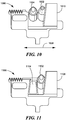
- Fig. 10 is a front view of an embodiment of a collimated shutter 1000.
- the collimated shutter 1000 includes two tubes 1002 and 1004.
- Each of the tubes 1002 and 1004 has a different diameter central bore (and, thus, a different distal exit aperture dimension) and/or a different length.
- the tubes may be arranged in any order of diameters or lengths.
- the collimated shutter 1000 may be translated laterally, as indicated by an arrow 1006, such as by a gear rack 1008 and a spur gear (not shown) or by any other suitable mechanism, into one of at least three positions.
- the primary x-ray beam is prevented from reaching the sample, and an angled portion 1010 reflects the primary x-ray beam into the detector, as previously discussed.
- one of the tubes (1002 or 1004) is aligned between the primary x-ray source and the sample.
- the other tube is aligned between the primary x-ray source and the sample.
- the collimated shutter 1000 includes two collimators defined, respectively, by the two tubes 1002 and 1004.
- Each of the tubes 1002 and 1004 produces a different diameter x-ray spot on a sample.
- the longer tube has the smaller central bore diameter (at the end of the tube closest to the sample), so the tube that produces the smaller primary x-ray spot is closer to the sample surface than the tube that produces the larger spot.
- the two tubes 1002 and 1004 have central bore diameters of about 3 mm and about 8 mm, respectively, and the lengths of the tubes 1002 and 1004 are such that, when each tube is in position to allow the x-ray beam to illuminate a spot on the sample, the end of the tube is about 3 mm or about 8 mm, respectively, from the surface of the sample.
- Other pairs of bore diameters and lengths may be used to produce other sizes of x-ray spots.
- Other embodiments may have other numbers of tubes and, thus, produce other numbers of diameters of x-ray spots.
- Fig. 11 is a front view of another embodiment of a collimated shutter 1100.
- the collimated shutter 1100 includes a tube 1102 and a large hole 1104.
- the large hole 1104 is similar to the hole 906 described above, with respect to Fig. 9 .
- the collimated shutter 1100 may be translated laterally into one of at least three positions, as discussed above. In one position, the primary x-ray beam is prevented from reaching the sample, and an angled portion 1106 reflects the primary x-ray beam into the detector, as previously discussed. In the second position, the tube 1102 is aligned between the primary x-ray source and the sample. In the third position, the hole 1104 is aligned between the primary x-ray source and the sample.
- the tube 1102 and the hole 1104 produce different size primary x-ray spots on the sample.
- the dimensions of the tube 1102 may be selected to produce a small spot, such as a spot having a diameter of between about 0.3 mm and about 8 mm, as discussed above.
- the dimensions of the hole 1104 may be as in the prior art to produce an x-ray spot having a diameter of about 1 cm. Larger or smaller spots may, of course, be produced by varying the dimensions of the tube 1102 or the hole 1104.
- collimated shutters have been described as including one or more tubes.
- Each of these tubes forms at least a part of a collimator.
- tubular collimators with circular inside cross-sections are preferred due to the relative ease of manufacturing such shapes, other shapes (such as square, oval or triangular cross-sections) are acceptable.
- the inside walls of a collimator may be stepped or smooth, or the walls may have other types of transitions between sections having different inside diameters or shapes.
- collimated shutters have been described as being movable laterally to interpose either a tubular collimator (or one of several tubular collimators) or a reflecting surface between a primary x-ray source and a sample
- other motions such as a circular motion
- other mechanisms such as a turret, may be used to selectively move a desired collimator or reflecting surface into place between the x-ray source and the sample.
- an analyzer may include a tubular collimator that does not move into and out of position to permit a primary x-ray beam to illuminate a spot on a sample.
- the tubular collimator may be fixed in place.
- Electric power to an x-ray tube may be interrupted, such as under the control of a processor, to prevent x-rays from exiting the analyzer window.
- a shutter may be interposed between the primary x-ray source and the collimator or the sample to interrupt the x-ray beam and, optionally, reflect the x-ray beam to the detector.
- Such a shutter may include a solid surface, an iris or any other suitable mechanical, electronic, chemical or electrochemical (such as polymer dispersed liquid crystal, which changes x-ray opacity in response to an applied electric field) mechanism for selectively blocking the x-ray beam.
- the shutter may be separate from the tubular collimator.
- fluorescent x-rays from a sample may react with portions of the tube 308 to produce spurious fluorescent or reflected x-rays from the tube 308.
- fluorescent or scattered primary x-rays from the sample may strike other portions of the sample or the analyzer and induce spurious secondary fluorescence. These spurious x-rays may reach the detector 314 and contribute noise to the analysis system.
- Fig. 12 is a perspective view of a detector collimator 1200, according to one embodiment of the present invention.
- Fig. 13 is a cross-sectional view through the snout 202 of an XRF analyzer that includes the detector collimator 1200 of Fig. 12 .
- a portion 1202 of the end of the detector collimator 1200 closest to the sample may be tapered, as discussed above with respect to the tube 308.
- the inside walls, as seen in a cross-section of the detector collimator 1200 may be parallel or non-parallel, i.e.
- the detector collimator 1200 may have an overall taper. Furthermore, the inside walls of the detector collimator 1200 may be smooth or stepped or they may have some other shape.
- the detector collimator 1200 should be made of an x-ray opaque material, as discussed above with respect to the collimated shutter 300.
- the inside walls of the detector collimator 1200 may be covered or clad with one or more layers of material(s) that reduce the intensity of spurious radiation scattered from, or generated in, the walls of the detector collimator 1200. As shown schematically in Fig. 14 , the detector collimator 1200 prevents many of the spurious x-rays from reaching the detector 314.
- the entrance 1204 ( Fig. 12 ) to the detector collimator, i.e., the opening closest to the surface 604 of the sample, should be no larger than the effective spot size, as seen by the detector 314 on sample surface.
- the entrance 1204 may, however, be smaller than the effective spot size.
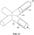
- a source collimator 1500 defines a cylindrical or slightly conical field of illumination 1502, and a detector collimator 1504 defines a cylindrical or slightly conical field of view 1506.
- the detector receives x-rays emanating from only a volume defined by the intersection of the two fields 1502 and 1506.
- the size and location of a sample of interest at or slightly below the surface of the sample may be specified, and scattered or fluorescent x-rays from other portions of the sample or from elsewhere may be prevented from reaching the detector 314.
- Some embodiments of the present invention include a digital camera inside the snout to facilitate aiming the analyzer.
- An image produced by the digital camera may be displayed on the touchscreen 210 ( Fig. 2 ).
- a reticule that indicates where the x-ray spot is, or would be, is also shown on the touchscreen 210.
- the image may be displayed on a remote screen, such as a screen attached to a computer.
- the analyzer may include a port by which the analyzer may send the image to the remote display over a wired or wireless link.
- the image may be digitally zoomed or otherwise reoriented to the center or another selected portion of the camera's image plane.
- Commands to zoom, pan, tilt, etc. the image may be entered by a user via the touchscreen 210 or the operator interface buttons 212.
- a digital camera 316 such as a single-chip, lensed digital camera, is positioned within the snout 202 and oriented towards the portion of the sample where the fluorescent x-rays 312 are generated.
- a suitable camera is available from Micron Technology, Inc., Boise, ID under part number MT9V112, and a suitable lens is available from Edmunds Optics, Inc., Barrington, NJ under part number NT47-725.
- Appropriate software to process signals from the digital camera 316 is available under the tradename DirectShow API from Microsoft, Redmond, WA.
- a visible light source 318 such as a surface-mounted LED, is mounted above the detector 314 to illuminate the surface of the sample visible through the window 310. If a colored film, such as an orange Kapton polyimide film, covers the window 310, an LED that produces a similar color light should be selected. Otherwise, other colors of light produced by the LED will not be efficiently transmitted through the colored film, and these other colors of light will not materially contribute to an image produced by the camera 316. Consequently, energy consumed by the LED to produce the other colors of light will be essentially wasted, thereby decreasing the amount of time the analyzer may be operated before the battery 214 must be recharged.
- a colored film such as an orange Kapton polyimide film
- the camera 316 should be mounted so the camera's image plane is parallel to the surface of the sample, and so the camera is centered over the x-ray spot.
- the tube 308 or the angled portion 400 may block the camera's view.
- the camera may, therefore, be mounted off-center, relative to the x-ray spot and angled, relative to a line normal to the sample surface.
- the processor may execute a flattening algorithm to remove most or all of the distortion before displaying the corrected image on the touchscreen 210 or elsewhere.
- the flattening algorithm may employ a homography matrix or other well-known methods for flattening an image.
- an image produced by a camera within the snout of an analyzer may assist a user in aiming an analyzer at a desired location on a sample
- most digital cameras are not sensitive to x-rays, thus most such images would not directly show the x-ray spot.
- Various embodiments are disclosed for assisting the user in aiming the analyzer.
- Some embodiments of the present invention project a spot of visible light on the sample where the x-ray spot is, or would be, to assist a user in aiming the analyzer.
- a laser diode or LED 616 may be attached to the collimator tube 308 or elsewhere and aimed so a beam produced by the laser diode or LED 616 creates a visible spot on a portion of the surface 604 of the sample where the x-ray spot is or would be.
- the visible spot need not be the same size as the x-ray spot.
- the visible light source may be pulsed, so the visible spot blinks to facilitate viewing features on the surface of the sample.
- some embodiments of the present invention include a fluorescent screen 2000 in or near the window 310 of the snout 202, so the primary x-ray beam produces a visible spot that may be imaged by the camera (not shown in Fig. 17 ).
- the fluorescent screen may be made of any suitable material that produces visible light when illuminated by x-rays.
- a reticule that indicates where the x-ray spot is, or would be, to the image produced by the camera.
- a reticule may be a cross-hair, hash mark or other shape or combination of shapes that assist the user in aiming an analyzer at a location of interest on a sample.
- the reticule may include a circle or other shape that approximates the shape, size and location of an outline of the x-ray spot.
- the term "reticule” means any shape or shapes that are added to the image produced by the camera to facilitate aiming the analyzer.
- the term reticule is not limited to cross hairs, concentric circles, fine dots and the like, as may be the case when the term is used in other contexts, such as microscopes and other optical instruments.
- Fig. 16 is an exemplary image produced by a camera in the snout of an analyzer.
- the image includes an electrical component 1900 (such as a resistor) soldered to a printed circuit board 1902.
- the image also includes a circuit trace 1904 and a solder joint 1906 between a lead of the component 1900 and the trace 1904.
- a reticule circle 1908 is generated by the analyzer and included in the image.
- An optional reticule cross hair 1910 may also be generated by the analyzer and included in the image to indicate the center of the x-ray spot.
- a color may be dynamically chosen for all or a portion of the reticule to ensure the reticule is visible against a background.
- a color is dynamically chosen for the reticule cross hair 1910, based on the color of underlying pixels, so the cross hair 1910 is always visible, regardless of the color of the underlying pixels.
- the color of the cross hair 1910 is dynamically chosen to be one of two values (referred to as a light color and a dark color), such as black and white, as follows.
- An average brightness is calculated for the pixels that are to be occupied by the cross hair 1910.
- the brightness of a pixel (for example, a value between 0 and 255) is defined as one third of the sum of the pixel's red, green and blue color intensities.
- T a predetermined threshold value
- H a predetermined hysteresis value
- a color may be dynamically chosen for all or a portion of the reticule to make it translucent.
- a base color such as reddish orange
- the color of each pixel of the circle 1908 is then dynamically modified, based on the color of an underlying pixel, so text or other features on the surface of the sample are not completely obscured by the circle 1908.
- the pixel's red, green and blue intensities are each modified by multiplying the intensity by a number K (0 ⁇ K ⁇ 1) to simulate partial light transmission.
- the red, green and blue intensities of the reticule's base color are scaled (multiplied) by 1-K and added to the modified red, green and blue intensities, respectively, of the underlying pixel.
- the location of a reticule within an image produced by an analyzer should accurately reflect the location of the x-ray spot. Manufacturing tolerances may, however, cause analyzer-to-analyzer variations in the location of the x-ray spot on the surface of a sample.
- the location of the x-ray spot on the surface of the sample may change. It may, therefore, be necessary or desirable to calibrate or re-calibrate the location of the reticule, such as during manufacturing, after replacement of the x-ray source or during analyzer maintenance.
- calibrating Various methods and apparatus are disclosed for calibrating or recalibrating (collectively hereinafter referred to simply as calibrating) the location, shape and/or size of a reticule.
- a calibration target may be used to facilitate calibrating the reticule.
- the methods and apparatus for calibrating the location, shape and/or size of a reticule do not form a part of the present invention.
- Fig. 18 is a perspective view of a reticule calibration target 2100.
- the calibration target 2100 includes a plug 2102 embedded in a sheet 2104 or adhered to the surface of the sheet 2104.
- the plug 2102 should be relatively small, i.e., on the order of the size of the x-ray spot.
- the plug 2102 is made of a different material than the sheet 2104.
- the plug has a diameter of about 3.5 mm, a thickness of about 10 mil and is made of copper, and the sheet may be made of titanium, a solid polymer or a solid polymer with titanium.
- the sheet is about 12 mm-thick, about 31 mm in diameter, and includes a solid polymer containing 5% titanium as an oxide.
- the calibration target 2100 also includes indicia 2106 and 2108 in the form of crosshairs or a spot centered on the plug 2102.
- the calibration sheet 2100 shown in Fig. 18 is square, the calibration target may be other shapes, such as a circle.
- the front wall of the snout of an analyzer is pressed against the calibration target 2100, such that the window of the snout covers the plug 2102. Measurements are taken, and the analyzer is moved (relative to the calibration target 2100) after each measurement, until a maximum reading (within some error tolerance) for the material of the plug 2102 is taken.
- the x-ray spot can be assumed to be centered on the plug 2102, and the reticule may be made to correspond to the location of the plug 2102.
- An image of the plug 2102 may be displayed on the touchscreen or another display screen, and the location of the reticule may be made to correspond with the location of the plug 2102 in the image.
- the indicia 2106 and 2108 may facilitate aligning the reticule or portions thereof with the center of the plug 2102.
- the above-describe procedure may involve alternating taking measurements and moving the analyzer until a maximum reading for the material of the plug 2102 is taken and, simultaneously, a minimum reading for the material of the sheet 2104 is taken.
- the plug 2102 is made of the material that is not detectable by the analyzer, the above-described procedure may be used until a minimum reading for the material of the sheet 2104 is taken. In this regard, the plug 2102 may be replaced by a hole in the sheet 2104.
- the distal portion of the tube 308 may be visible in the image.
- the analyzer may be positioned, relative to the calibration target 2100, such that an imaginary extension of the tube 308 intersects the plug 2102.
- the reticule may be made to correspond to the location of the plug 2102 in the image. The location of the reticule may be refined as described above or below.
- Fig. 19 is a plan view of another reticule calibration target 2200.
- the calibration target 2200 includes a plurality of pie-shaped sections 2202, 2204, 2206 and 2208, each of which is detectable by the analyzer.
- pie-shaped means two adjacent sides of each section form an angle (the "vertex angle"), exemplified by angle 2210.
- the calibration target 2200 shown in Fig. 19 includes four sections, other numbers of sections may be used; however, each section 2202-2208 is made of a different material.
- the reticule calibration target 2200 shown in Fig. 19 includes an iron section 2202, a zinc section 2204, a copper section 2206 and a nickel section 2208; however, other combinations of detectable materials may be used.
- all the pie-shaped sections 2202-2208 have identical vertex angles (exemplified by angle 2210) where the pie-shaped sections meet in the center 2212 of the calibration target 2200.
- angle 2210 vertex angles
- the calibration algorithm should take into account the expected ratios of materials in the respective sections, based on the respective vertex angles.
- the sum of the vertex angles of all the sections 2202-2208 is 360 degrees.
- the front wall of the snout of an analyzer is pressed against the calibration target 2200, such that the window of the snout covers the center 2212 of the calibration target 2200. Measurements are taken, and analyzer is moved (relative to the calibration target 2200) after each measurement, until a measurement is taken that indicates equal amounts of all the materials of the calibration target 2200.
- the x-ray spot may be assumed to be centered on the center 2212 of the calibration target 2200, and the reticule may be made to correspond to the location of the center 2212.
- the center 2212 may be marked on the calibration target 2200, such as by a dot, crosshairs or other indicia (not shown).
- the calibration target 2200 may include other indicia that facilitate aligning the reticule or portions thereof with the location of the x-ray spot.
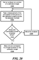
- a calibration target to calibrate a reticule is described by a flowchart in Fig. 20 .
- an analyzer is aimed at a portion of a calibration target.
- a measurement is taken of the composition of the portion of the calibration target, at which the analyzer is aimed.
- control passes to 2306, where the analyzer is moved to another location on the calibration target, and then control returns to 2302.
- ⁇ calibrating the location of a reticule involve modeling an expected x-ray fluorescence response function to a calibration target and aligning the reticule to measured readings, according to the model.
- One such arrangement uses a calibration target similar to the calibration target 2100 described above, with reference to Fig. 18 .
- An expected x-ray fluorescence response function to the plug 2102 is shown graphically in Fig. 24 .
- the expected response function is a paraboloid 2700, i.e., a surface generated by rotating a parabola 2702 about its axis of symmetry 2704.
- the paraboloid 2700 is assumed to be aligned with the plug 2102, such that the axis 2704 is normal to the surface of the calibration target, and the axis 2704 passes through the center of the plug 2102. As described in more detail below: five readings are taken with the analyzer; an equation for the paraboloid 2700 is fitted to the five readings; the location of the apex 2706 of the paraboloid is determined from the equation; and the reticule is aligned with the apex of the paraboloid 2700.
- the analyzer is aimed at the calibration target, such that the x-ray spot approximately corresponds with the location of the plug 2102. This may be accomplished by visually aligning the plug 2102 with an imaginary extension of the tube 308, as described above.
- the location on the image of the sample where the plug 2102 is visible is identified to the analyzer or external computer coupled to the analyzer's camera. In one embodiment, this is accomplished by causing a cross-hair cursor to correspond with the location of the plug 2102 in the image. For example, an operator may position the cursor in the image with a mouse or joystick. An x-ray fluorescence reading is taken at this location, which is referred to as the first location.
- the analyzer or external computer calculates at least four additional locations proximate the first location.
- the four additional locations 2800, 2802, 2804 and 2806 are located at the corners of a square centered on the first location 2808.
- the four additional locations 2800-2806 are located at the corners of a 2 mm x 2 mm square. Other regular or irregular shapes, and other sizes of shapes, may be used to select the additional locations.
- the analyzer or external computer generates a reticule or other indicator on the screen at the location of one of the additional locations 2800-2806, and the operator repositions the analyzer so the plug 2102 is centered in the reticule. A second x-ray fluorescence reading is taken at this location. The process is repeated for each of the other additional locations 2800-2806, producing a total of five readings.
- x and y are coordinates of a point in an x-y plane and z is the height of the point over the x-y plane, i.e., the measured concentration of the material of the plug 2102.
- x and y are coordinates of the locations 2800-2808 in the plane of the locations.
- X 0 and Y 0 are coordinates of the apex 2706 of the paraboloid 2700
- a 0 and A 1 are constant coefficients, A 0 being the value of z at the apex 2706. The five readings are used to calculate the constant coefficients.
- the coordinates of the apex 2706 are calculated, and the reticule is made to correspond to the location of the apex 2706.
- a calibration method using a paraboloid may use two or more one-dimensional curves to model the response function.
- two parabolas are used.
- at least five sample points are taken to fit the curves.
- a calibration target and a model of a response function to calibrate a reticule is described by a flowchart in Fig. 26 .
- measurements are taken at a plurality of distinct locations on the calibration target.
- One of the measurements may be taken at a location that approximates a predetermined location, such as a plug, on the calibration target.
- the locations of the other measurements may be calculated based on the location of the predetermined location.
- a curve representing an expected response function is fit to the measurements taken at 2900.
- the response function may be a three-dimensional function, such as a paraboloid, or two or more two-dimensional functions, such as parabolas.
- the location of the reticule is made to correspond to a predetermined location on the curve, such as a peak in the curve.
- a sheet of fluorescent material may be used to calibrate the size or shape of a reticule.
- the front wall of the snout of an analyzer is pressed against the sheet of fluorescent material, and the analyzer is operated.
- the size and shape of the x-ray spot are made apparent by a spot of visible light given off by the fluorescent material where it is excited by the x-ray spot.
- the reticule may be made to correspond to the size and/or shape of the visible spot.
- Other methods for calibrating the size or shape of the reticule include other devices for detecting x-rays, including active x-ray detectors, such as a silicon PIN diode, cadmium-telluride detector connected to an amplifier or proportional counter.
- the detector may be position sensitive in one or two dimensions.
- An image of a sample produced by a camera within the snout of an analyzer may be automatically annotated with results of an analysis of the sample.
- chemical constituents 1912 found in the sample under test may be displayed, such as in the upper-right corner of the touchscreen.
- Other information, such as the time and date 1914, on which the sample is analyzed, an automatically generated or user-entered sample number, the analyzer's serial number, model number and software revision level or warning messages generated by the analyzer (such as in connection with purging the instrument of ambient gas, as discussed below) may be included in the image.
- the user may enter text via the interface buttons 212 ( Fig.
- a soft keyboard displayed on the touchscreen 210 may also be used to annotate the image.
- non-textual information such as a graph depicting a spectrum or chemical composition, may be included in the image. Pixels of the annotations may be opaque or translucent, and their colors may be dynamically chosen, as discussed above.
- An analyzer may include a digital camera positioned to capture images of portions of a sample that are larger than the sample portion covered by the snout of the analyzer.
- the analyzer 200 of Fig. 2 has an optional external-view digital camera 216.
- a second external-view digital camera (not visible) may be included on the other side of the analyzer 200 to augment the view provided by the camera 216. Images provided by one or more such external-view cameras may be included with, associated with, or used instead of, images produced by a camera inside the snout of the analyzer 200.
- tubing of such a "wearable" gas tank system can, however, pose a tripping danger to an operator.
- the tubing may become entangled with, or knock over, other equipment, as the operator moves about.
- An analyzer 2400 includes a port 2402, to which a gas line, such as a flexible tube 2404, may be connected.
- the flexible tube 2404 is connected to a wearable gas tank 2406.
- the gas line includes a break-away coupling 2408. If more than a predetermined amount of tension is applied along the length of the flexible tube 2404, such as because the tube becomes caught on a fixed or heavy object, the break-away coupling 2408 separates into two sections. One section remains connected to the portion 2410 of the tube 2404 that is connected to the tank 2406.
- the other section 2412 remains connected to the portion 2412 of the tube 2404 that is connected to the analyzer 2400.
- the section that remains connected to portion 2410 of the tube includes an automatic shut-off valve that is activated when the two portions 2410 and 2412 separate from each other.
- the break-away coupling 2408 may be positioned elsewhere along the flexible tube 2404, such as proximate the analyzer 2400 or at the port on the analyzer.
- more than one break-away coupling may be included along the length of the flexible tube 2304. In one embodiment, one break-away coupling is positioned proximate the tank, and another break-away coupling is positioned proximate the analyzer 2400.
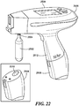
- FIG. 22 illustrates an analyzer 2500 that includes a fitting (not visible), to which a small gas tank (also referred to as a gas "cartridge”) 2502 may be connected to provide a gas supply, without the drawbacks of a wearable tank or a long flexible tube.
- a small gas tank also referred to as a gas "cartridge”
- the gas cartridge 2502 may be coupled to the analyzer 2500 by screwing a threaded portion 2504 on the neck of the cartridge into a corresponding female threaded portion of the coupling on the analyzer 2500.
- the coupling on the analyzer includes a sharp point or other suitable member to pierce a seal on the cartridge 2502, as the cartridge is threaded into the coupling, to allow gas to flow from the cartridge 2502 to the analyzer.
- the analyzer may include an appropriate shut-off valve, pressure regulator, flow-control valve, etc. as needed to control gas flow from the cartridge 2502. Such a gas cartridge 2502 may be easily replaced when the gas within the cartridge has been exhausted.
- the coupling on the analyzer 2500 may be located elsewhere on the exterior or interior of the analyzer 2500.
- the coupling may be located on the top of the snout or behind or below the back 2506 of the analyzer 2500.
- a portion of the housing of the analyzer (such as a hinged or removable door) may be opened to reveal a recess, into which the gas cartridge 2502 may be inserted, after which the door is closed.
- the gas cartridge may be co-located with a rechargeable battery in a detachable portion 2508.
- a bore 2510 receives a disposable or refillable gas cartridge.
- a suitable coupling in the bottom of the handle portion 2512 of the analyzer mates with the neck of the gas cartridge and pierces the seal when the detachable portion 2508 is attached to the handle portion 2512 of the analyzer 2500.
- a permanent, refillable gas cartridge (not shown) is located in the detachable portion 2508.
- the detachable portion 2508 includes a suitable neck or coupling to mate with a coupling in the bottom of the handle portion 2512.
- This gas cartridge may be refilled, such as when the detachable portion 2508 is detached from the rest of the analyzer 2500 to recharge the battery.
- a recharging station (not shown) may include a facility for recharging the battery and for refilling the gas cartridge. Such a recharging station may be coupled to a sufficiently large tank of gas to refill a plurality of gas cartridges in series or in parallel.
- the snout should include a relatively gas-tight chamber, into which the gas is introduced.
- a fluid communication path is established between the source of the gas (i.e., a wearable tank, a gas cartridge, a freestanding tank or any other suitable gas source, collectively hereinafter referred to as a tank) and the chamber.
- the chamber may include the collimated shutter 300 and other components described above.
- the window 310 may be fitted with a pane 2600, such as a sheet of polypropylene, fitted to the window opening with a gas-tight gasket 2602.
- the pane 2600 should be relatively transparent to the excitation beam and the fluorescent x-rays.
- the pane 2600 should exhibit a relatively high degree of resistance to embrittlement and degradation by the excitation energy beam and the fluorescent x-rays, as well as resisting thermal softening and deterioration from heat generated by exposure to these energy sources.
- a suitable material for the pane 2600 is available from Chemplex Industries, Inc., Palm City, FL, under the tradename Prolene.
- An analyzer may include an automatic mechanism for controlling the amount of purge gas that is admitted into the chamber, so that a minimum amount of gas is used, yet the interior of the chamber is sufficiently purged of ambient gas (air) to eliminate or adequately limit absorption of x-rays by the ambient gas.
- the analyzer may include a sensor for determining if an adequate (or inadequate) amount of purge gas is present in (or entering) the chamber or if an excessive (or a sufficiently small) amount of ambient gas is present in the chamber. This determination may be made directly (such as by testing the ambient or purge gas or by measuring the purge gas flow rate) or indirectly (such as by measuring a quantity that is correlated to the amount of ambient or purge gas).
- the analyzer may automatically control introduction of the purge gas, based on an output from the sensor. If insufficient purge gas or excessive ambient gas is detected in or entering the chamber, the analyzer may perform one or more actions. Among other actions, the analyzer may: refrain from storing results from an analysis, display a warning message along with results of the analysis or activate an audible alarm (such as a tone generator) or a visible alarm (such a light or an indicator on the touchscreen). An alarm may also be raised if an insufficient amount of gas can be provided by the tank, such as because the tank is empty.
- an audible alarm such as a tone generator
- a visible alarm such a light or an indicator on the touchscreen
- a flow rate regulator introduces the purge gas into the chamber at a predetermined constant volumetric rate, optionally automatically adjusted for changes in ambient atmospheric pressure.
- the rate may be selected to approximate or exceed a previously estimated, calculated or measured rate at which the purge gas escapes from the chamber.
- the flow rate may be restricted (such as to the predetermined amount) by a constriction in the fluid communication path and/or by a pressure regulator.
- the flow rate of the purge gas is automatically controlled in response to an output from a sensor.
- the flow rate may be automatically increased. If a sufficiently small amount of ambient gas is detected, or if a sufficient amount of purge gas is detected, the flow rate may be automatically decreased, possibly to zero.
- An electrically-actuated valve may be controlled by a processor or other control circuit in the analyzer to control the purge gas flow rate.
- the flow rate may be controlled by selectively opening and closing a binary valve (i.e., a valve that is either fully open or fully closed, with no intermediate settings) or by selectively operating a variable-opening valve. If a binary valve is used, particularly if such a valve is toggled rapidly, the fluid communication path may include an accumulator downstream from the valve to provide the purge gas at a more steady pressure.
- the flow rate of the purge gas may be measured by a flow rate sensor in the fluid communication path. If the flow rate is measured to be less than a predetermined value, the flow rate may be automatically increased by adjusting or operating a valve.
- the amount of purge gas in the chamber may be determined by measuring the pressure in the chamber. If the pressure is less than a predetermined valve, the purge gas flow rate may be automatically increased.
- the amount of ambient gas in the chamber may be measured by measuring the amount of argon in the chamber using x-ray fluorescence, such as during a sample analysis, as described above.
- the amount of argon in the chamber is proportional to the amount of air in the chamber. Thus, argon may be used as a proxy for air in the chamber.
- the amount of argon detected in the chamber is greater than a predetermined value, automatically more purge gas may be introduced into the chamber or the flow rate may be increased.
- the predetermined value may be a small value or zero, within the detection limits of the XRF analyzer. However, if silver is present in the path of the x-rays, the silver spectral lines (at 2.98 KeV and 3.15 KeV) may overlap with argon spectral lines (at 2.96 KeV and 3.19 KeV). Thus, as the argon is flushed from the chamber, the apparent height of the argon lines may be reduced, but not to zero. Thus, the predetermined value may be based on the expected heights of the silver lines after the argon has been purges from the chamber.
- the helium concentration may be measured by making use of the high thermal conductivity of helium, compared to air. In one embodiment, the amount of electrical current needed to maintain a constant temperature of a thermistor that is mounted in the chamber is monitored. If the amount of current varies, the concentration of helium may be assumed to have varied, and more or less helium may be introduced to compensate.
- analyzers described above may be used in conjunction with other types of analyzers, such as analyzers that employ arc/spark optical emission spectroscopy (OES), laser-induced breakdown spectroscopy (LIBS) or a combination thereof.
- OES arc/spark optical emission spectroscopy
- LIBS laser-induced breakdown spectroscopy
- these aspects include, but are not limited to: the detector collimator, digital camera, image correction, image annotation, co-archiving of sample image and analysis data, reticule, reticule calibration, gas purge (possibly using argon or another gas), break-away coupling, gas cartridge and purge gas flow control.
- a chemical composition analyzer has been described as including a processor controlled by instructions stored in a memory.
- the memory may be random access memory (RAM), read-only memory (ROM), flash memory or any other memory, or combination thereof, suitable for storing control software or other instructions and data.
- RAM random access memory
- ROM read-only memory
- flash memory any other memory, or combination thereof, suitable for storing control software or other instructions and data.
- instructions or programs defining the functions of the present invention may be delivered to a processor in many forms, including, but not limited to, information permanently stored on non-writable storage media (e.g. read-only memory devices within a computer, such as ROM, or devices readable by a computer I/O attachment, such as CD-ROM or DVD disks), information alterably stored on writable storage media (e.g. floppy disks, removable flash memory and hard drives) or information conveyed to a computer through communication media, including wired or wireless computer networks.
- non-writable storage media e.g. read-only memory devices within a computer, such as ROM, or devices readable by a computer I/O attachment, such as CD-ROM or DVD disks
- writable storage media e.g. floppy disks, removable flash memory and hard drives
- communication media including wired or wireless computer networks.
- the functions necessary to implement the invention may alternatively be embodied in part or in whole using firmware and/or hardware components, such as combinatorial logic, Application Specific Integrated Circuits (ASICs), Field-Programmable Gate Arrays (FPGAs) or other hardware or some combination of hardware, software and/or firmware components.
- firmware and/or hardware components such as combinatorial logic, Application Specific Integrated Circuits (ASICs), Field-Programmable Gate Arrays (FPGAs) or other hardware or some combination of hardware, software and/or firmware components.
Landscapes
- Physics & Mathematics (AREA)
- Health & Medical Sciences (AREA)
- Life Sciences & Earth Sciences (AREA)
- Chemical & Material Sciences (AREA)
- Analytical Chemistry (AREA)
- Biochemistry (AREA)
- General Health & Medical Sciences (AREA)
- General Physics & Mathematics (AREA)
- Immunology (AREA)
- Pathology (AREA)
- Analysing Materials By The Use Of Radiation (AREA)
Claims (12)
- In sich geschlossenes Handtestgerät (200) zum Analysieren einer Zusammensetzung einer Probe, wobei das Testgerät (200) Folgendes beinhaltet:eine Quelle (302) zum Erzeugen eines Strahls (304) eindringender Strahlung zum Beleuchten eines Flecks auf wenigstens einem Abschnitt der Probe (604), wobei dadurch ein Antwortsignal (312) von der Probe (604) erzeugt wird, wobei das Antwortsignal (312) Fluoreszenzstrahlung umfasst, die charakteristisch für Elemente in der Probe (604) ist;einen kollimierten Verschluss (1000) für den Strahl (304), einen Detektor (314) zum Empfangen des Antwortsignals (312) und zum Erzeugen eines Ausgangssignals, das Spektraldaten darstellt;einen Prozessor, der mit dem Detektor (314) gekoppelt und programmiert ist, um das Ausgangssignal von dem Detektor zu verarbeiten;eine Batterie (214), die die Quelle und den Prozessor mit Strom versorgt; undeinen Detektorkollimator (1200), der entlang eines Lichtwegs zwischen dem Fleck und dem Detektor (314) derart positioniert ist, dass das Antwortsignal (312) durch den Detektorkollimator (1200) läuft, bevor es den Detektor (314) erreicht, dadurch gekennzeichnet, dass der kollimierte Verschluss (1000) ein erstes Rohr (1002) und ein zweites Rohr (1004) beinhaltet, die jeweils eine zentrale Bohrung mit unterschiedlichem Durchmesser und/oder eine unterschiedliche Länge aufweisen, wobei der kollimierte Verschluss (1000) ferner einen beweglichen Verschluss, der in einer von wenigstens drei Positionen positioniert ist, eine erste Position, die verhindert, dass der Strahl (304) eindringender Strahlung die Probe (604) erreicht, eine zweite Position, in der eines des ersten und des zweiten Rohrs (1002, 1004) zwischen der Quelle (302) und der Probe (604) ausgerichtet ist, und eine dritte Position umfasst, in der das andere des ersten und des zweiten Rohrs (1004) zwischen der Quelle (302) und der Probe (604) ausgerichtet ist.
- In sich geschlossenes Handtestgerät (200) zum Analysieren der Zusammensetzung einer Probe, wobei das Testgerät (200) Folgendes beinhaltet: eine Quelle (302) zum Erzeugen eines Strahls (304) eindringender Strahlung zum Beleuchten eines Flecks auf wenigstens einem Abschnitt der Probe (604), wobei dadurch ein Antwortsignal (312) von der Probe (604) erzeugt wird, wobei das Antwortsignal (312) die Fluoreszenzstrahlung umfasst, die charakteristisch für Elemente in der Probe (604) ist;
einen kollimierten Verschluss (1100) für den Strahl (304), einen Detektor (314) zum Empfangen des Antwortsignals (312) und zum Erzeugen eines Ausgangssignals, das Spektraldaten darstellt, einen Prozessor, der mit dem Detektor (314) gekoppelt und programmiert ist, um das Ausgangssignal von dem Detektor zu verarbeiten, eine Batterie (214), die die Quelle und den Prozessor mit Strom versorgt; und
einen Detektorkollimator (1200), der entlang eines Lichtwegs zwischen dem Fleck und dem Detektor (314) derart positioniert ist, dass das Antwortsignal (312) durch den Detektorkollimator (1200) läuft, bevor es den Detektor (314) erreicht;
dadurch gekennzeichnet, dass der kollimierte Verschluss (1100) ein Rohr (1102) und ein Loch (1104) beinhaltet, die jeweils unterschiedliche Abmessungen aufweisen, wobei der kollimierte Verschluss (1100) ferner einen beweglichen Verschluss, der in einer von wenigstens drei Positionen positioniert ist, eine erste Position, die verhindert, dass der Strahl (304) der eindringenden Strahlung die Probe (604) erreicht, und eine dritte Position umfasst, in der das Loch (1104) zwischen der Quelle (302) und der Probe (604) ausgerichtet ist. - Testgerät (200) nach Anspruch 1 oder 2, wobei ein Ende (1202) des Detektorkollimators (1200), das der Probe (604) am nächsten liegt, verjüngt ist.
- Testgerät (200) nach Anspruch 1 oder 2, wobei ein Ende (1202) des Detektorkollimators (1200), das der Probe (604) am nächsten liegt, nicht größer als die wirksame Fleckgröße ist, die durch den Detektor (314) auf der Oberfläche der Probe (604) erkannt wird.
- Testgerät (200) nach Anspruch 1 oder 2, wobei die distale Austrittsöffnung (311) im Wesentlichen parallel zu einer Oberfläche der zu analysierenden Probe (604) ist und die zweite distale Austrittsöffnung (1204) im Wesentlichen parallel zu der Oberfläche der Probe (604) ist.
- Testgerät (200) nach Anspruch 1 oder 2, wobei die Querabmessung weniger als 8 mm und die zweite Querabmessung weniger als 3 mm beträgt.
- Testgerät (200) nach Anspruch 1 oder 2, wobei die Querabmessung weniger als 3 mm und die zweite Querabmessung weniger als 1 mm beträgt.
- Testgerät (200) nach Anspruch 1 oder 2, wobei sich der Kollimatorverschluss (1000, 1100) und der Detektorkollimator (1200) zusammen zwischen wenigstens zwei Positionen derart bewegen, dass, in einer ersten Position der wenigstens zwei Positionen, der Strahl (304) durch den Kollimatorverschluss (1000, 1100) läuft, um den Fleck zu beleuchten, und, in einer zweiten Position der wenigstens zwei Positionen, der Strahl (304) durch den Detektorkollimator (1200) läuft, um den Fleck zu beleuchten.
- Testgerät (200) nach Anspruch 1 oder 2, das ferner eine Digitalkamera (316) umfasst, die konfiguriert ist, um ein Bild von wenigstens einem Abschnitt der Probe (604) aufzunehmen.
- Testgerät (200) nach Anspruch 9, das ferner einen Anzeigebildschirm umfasst, auf dem das Bild angezeigt wird.
- Testgerät (200) nach Anspruch 9, wobei der Prozessor programmiert ist, um ein Fadenkreuz hinzuzufügen, das angibt, wo sich der Fleck zu dem durch die Kamera erzeugten Bild befindet oder befinden würde.
- Testgerät (200) nach Anspruch 9, das ferner einen Laser (616) umfasst, der ausgerichtet ist, um einen sichtbaren Fleck auf der Probe (604) an eine Stelle zu projizieren, die dem Fleck der eindringenden Strahlung entspricht.
Applications Claiming Priority (2)
| Application Number | Priority Date | Filing Date | Title |
|---|---|---|---|
| US88946507P | 2007-02-12 | 2007-02-12 | |
| PCT/US2008/053691 WO2008100914A2 (en) | 2007-02-12 | 2008-02-12 | Small spot x-ray fluorescence (xrf) analyzer |
Publications (2)
| Publication Number | Publication Date |
|---|---|
| EP2115439A2 EP2115439A2 (de) | 2009-11-11 |
| EP2115439B1 true EP2115439B1 (de) | 2021-01-13 |
Family
ID=39685826
Family Applications (1)
| Application Number | Title | Priority Date | Filing Date |
|---|---|---|---|
| EP08729626.5A Active EP2115439B1 (de) | 2007-02-12 | 2008-02-12 | Röntgenfluoreszenz-analysegerät mit kleinem spot |
Country Status (6)
| Country | Link |
|---|---|
| US (2) | US7916834B2 (de) |
| EP (1) | EP2115439B1 (de) |
| JP (1) | JP2010518406A (de) |
| CN (1) | CN101652655B (de) |
| CA (1) | CA2677908A1 (de) |
| WO (1) | WO2008100914A2 (de) |
Families Citing this family (81)
| Publication number | Priority date | Publication date | Assignee | Title |
|---|---|---|---|---|
| ATE441459T1 (de) * | 2004-06-30 | 2009-09-15 | Univ Rochester | Fotodynamische therapie mit räumlich aufgelíster dualspektroskopieüberwachung |
| KR20080064155A (ko) | 2005-10-14 | 2008-07-08 | 어플라이드 리써치 어쏘시에이츠 뉴질랜드 리미티드 | 표면 특징을 모니터링하는 방법 및 장치 |
| US20070282404A1 (en) * | 2006-04-10 | 2007-12-06 | University Of Rochester | Side-firing linear optic array for interstitial optical therapy and monitoring using compact helical geometry |
| US8064570B2 (en) * | 2006-12-20 | 2011-11-22 | Innov-X-Systems, Inc. | Hand-held XRF analyzer |
| US20100331927A1 (en) * | 2007-05-02 | 2010-12-30 | Cottrell William J | Feedback-controlled method for delivering photodynamic therapy and related instrumentation |
| WO2009032640A2 (en) * | 2007-08-28 | 2009-03-12 | Thermo Niton Analyzers Llc | Contactless memory information storage for sample analysis and hand-holdable analyzer for use therewith |
| US7684545B2 (en) * | 2007-10-30 | 2010-03-23 | Rigaku Innovative Technologies, Inc. | X-ray window and resistive heater |
| US8565507B2 (en) * | 2008-05-23 | 2013-10-22 | University Of Rochester | Automated placental measurement |
| US8107710B2 (en) | 2008-05-23 | 2012-01-31 | University Of Rochester | Automated placental measurement |
| CN102292029B (zh) | 2008-07-18 | 2014-11-05 | 罗切斯特大学 | 用于c扫描光声成像的低成本设备 |
| US20100298688A1 (en) * | 2008-10-15 | 2010-11-25 | Dogra Vikram S | Photoacoustic imaging using a versatile acoustic lens |
| WO2010054018A1 (en) * | 2008-11-04 | 2010-05-14 | Thermo Niton Analyzers Llc | Dynamic modification of shaping time in x-ray detectors |
| JP2010197229A (ja) * | 2009-02-25 | 2010-09-09 | Osaka City Univ | 蛍光x線分析装置 |
| US20100226476A1 (en) * | 2009-03-05 | 2010-09-09 | John Pesce | Low-Profile X-Ray Fluorescence (XRF) Analyzer |
| US8410451B2 (en) | 2009-04-09 | 2013-04-02 | Boss Physical Sciences Llc | Neutron fluorescence with synchronized gamma detector |
| EP2425234B1 (de) | 2009-04-30 | 2019-10-23 | Thermo Scientific Portable Analytical Instruments Inc. | Lokalisierung eines elements von interesse durch röntgenfluoreszenz-analyse verschiedener inspektionsvolumen |
| CN101776620B (zh) * | 2009-05-11 | 2014-06-25 | 中国建材检验认证集团股份有限公司 | 波长色散x荧光光谱仪的弯面晶体分光装置及其工作方法 |
| WO2011037945A2 (en) * | 2009-09-22 | 2011-03-31 | Boss Physical Sciences Llc | Organic-scintillator compton gamma ray telescope |
| US8223925B2 (en) | 2010-04-15 | 2012-07-17 | Bruker Axs Handheld, Inc. | Compact collimating device |
| JP5587035B2 (ja) * | 2010-05-27 | 2014-09-10 | 富士フイルム株式会社 | 可搬型放射線撮影装置システム |
| CN102384782A (zh) * | 2010-09-06 | 2012-03-21 | 杭州法珀激光科技有限公司 | 手持式激光光束分析仪 |
| JP2012163489A (ja) * | 2011-02-08 | 2012-08-30 | Shimadzu Corp | 蛍光x線分析装置 |
| US8938884B2 (en) | 2011-03-18 | 2015-01-27 | Spectrum Brands, Inc. | Electric hair grooming appliance including touchscreen |
| US9176080B2 (en) * | 2011-07-19 | 2015-11-03 | Olympus Ndt, Inc. | X-ray analysis apparatus with detector window protection feature |
| EP2955510B1 (de) * | 2011-11-25 | 2018-02-21 | Aribex, Inc. | Röntgenstrahlentfernungsanzeiger und zugehörige verfahren |
| US9179844B2 (en) | 2011-11-28 | 2015-11-10 | Aranz Healthcare Limited | Handheld skin measuring or monitoring device |
| USD697210S1 (en) * | 2012-02-28 | 2014-01-07 | X-Ray Optical Systems, Inc. | Handheld x-ray analyzer |
| JP6096418B2 (ja) * | 2012-04-12 | 2017-03-15 | 株式会社堀場製作所 | X線検出装置 |
| JP6096419B2 (ja) * | 2012-04-12 | 2017-03-15 | 株式会社堀場製作所 | X線検出装置 |
| CN104395983B (zh) * | 2012-04-20 | 2017-10-10 | 布鲁克Axs手持设备公司 | 用于保护辐射窗口的设备 |
| US8982338B2 (en) * | 2012-05-31 | 2015-03-17 | Thermo Scientific Portable Analytical Instruments Inc. | Sample analysis |
| US20140301531A1 (en) * | 2013-04-08 | 2014-10-09 | James L. Failla, JR. | Protective shield for x-ray fluorescence (xrf) system |
| US20140301530A1 (en) * | 2013-04-08 | 2014-10-09 | James L. Failla, JR. | Protective shield for x-ray fluorescence (xrf) system |
| US9310324B2 (en) * | 2013-09-24 | 2016-04-12 | Oxford Instruments Analytical Oy | X-ray fluorescence analyzer with safety features |
| ITRM20130705A1 (it) * | 2013-12-20 | 2015-06-21 | Ilaria Carocci | Metodo e apparato per l'analisi di materiali mediante fluorescenza per raggi x a fascio aperto |
| US9594033B2 (en) * | 2014-07-22 | 2017-03-14 | The Boeing Company | Visible X-ray indication and detection system for X-ray backscatter applications |
| DE102014115383A1 (de) * | 2014-08-01 | 2016-02-04 | Helmut Fischer GmbH Institut für Elektronik und Messtechnik | Handgerät sowie mobile Einrichtung zur Röntgenfluoreszenzanalyse |
| US9261459B1 (en) * | 2014-08-12 | 2016-02-16 | Ecolab Usa Inc. | Handheld fluorometer |
| USD740945S1 (en) * | 2014-10-31 | 2015-10-13 | Aranz Healthcare Limited | Handheld scanner |
| CA163498S (en) | 2015-02-13 | 2017-09-28 | Helmut Fischer Gmbh Inst Für Elektronik Und Messtechnik | Handheld x-ray fluorescence measuring instrument |
| JP6530926B2 (ja) * | 2015-02-20 | 2019-06-12 | 株式会社イシダ | X線検査装置 |
| US9739730B2 (en) * | 2015-03-03 | 2017-08-22 | Panalytical B.V. | Quantitative X-ray analysis—multi optical path instrument |
| US11308601B2 (en) * | 2015-04-29 | 2022-04-19 | Emhart Glass S.A. | Container inspection system with individual light control |
| WO2016187471A1 (en) * | 2015-05-20 | 2016-11-24 | Tribogenics, Inc. | X-ray fluorescence device calibration |
| WO2016208155A1 (ja) * | 2015-06-22 | 2016-12-29 | 富士フイルム株式会社 | 放射線照射装置、並びに放射線照射装置の制御方法およびプログラム |
| US9933375B2 (en) * | 2015-09-25 | 2018-04-03 | Olympus Scientific Solutions Americas, Inc. | XRF/XRD system with dynamic management of multiple data processing units |
| USD769447S1 (en) * | 2015-10-15 | 2016-10-18 | Olympus Scientific Solutions Americas Inc. | Casing of a hand held X-ray fluorescence (XRF) analyzer instrument |
| DE102015221323B3 (de) * | 2015-10-30 | 2016-08-04 | Airbus Defence and Space GmbH | Verfahren zum Nachweis von Oberflächenverunreinigungen mittels Röntgenfluoreszenzanalyse |
| FR3044416B1 (fr) * | 2015-11-27 | 2017-12-22 | Fondis Electronic | Contacteur de securite d'un analyseur a fluorescence x portable |
| FR3044417B1 (fr) * | 2015-11-27 | 2019-06-21 | Fondis Electronic | Volet obturateur a etalon de verification de justesse integre d'un analyseur a fluorescence x portable |
| DE102016002365A1 (de) * | 2016-02-25 | 2017-08-31 | Mischa Ounanian | Ladestation für die Versorgung von handbetriebenen ("Handheld") oder tragbaren ("Portable") Analysegeräten auf Basis von OES (Optical Emission Spectroscopy) oder LIBS (Laser Induced Breakdown Spectroscopy). |
| WO2017160705A1 (en) * | 2016-03-14 | 2017-09-21 | X-Ray Optical Systems, Inc. | Sample handling apparatus for pressurized fluids and x-ray analyzer applications thereof |
| US10667690B2 (en) * | 2016-04-02 | 2020-06-02 | Intel Corporation | Compressive sensing sparse sampling photoplethysmogram (PPG) measurement |
| US10013527B2 (en) | 2016-05-02 | 2018-07-03 | Aranz Healthcare Limited | Automatically assessing an anatomical surface feature and securely managing information related to the same |
| GB2551980A (en) * | 2016-06-30 | 2018-01-10 | Commw Scient Ind Res Org | Method and system for low level metal analysis of mineral samples |
| US10641718B2 (en) * | 2016-07-29 | 2020-05-05 | Bruker Handheld Llc | X-ray fluorescence analyzer |
| WO2018039624A1 (en) | 2016-08-26 | 2018-03-01 | The Texas A&M University System | Hand-held synchronous scan spectrometer for in situ detection of pathogens and mineral deficiency in blood |
| ES2952771T3 (es) * | 2016-09-15 | 2023-11-06 | Oxos Medical Inc | Sistemas de imágenes mejoradas |
| US11116407B2 (en) | 2016-11-17 | 2021-09-14 | Aranz Healthcare Limited | Anatomical surface assessment methods, devices and systems |
| US10281414B2 (en) | 2016-12-01 | 2019-05-07 | Malvern Panalytical B.V. | Conical collimator for X-ray measurements |
| US11903723B2 (en) | 2017-04-04 | 2024-02-20 | Aranz Healthcare Limited | Anatomical surface assessment methods, devices and systems |
| US11169100B2 (en) * | 2018-04-02 | 2021-11-09 | Sciaps, Inc. | Portable, hand held aluminum alloy XRF analyzer and method |
| CA3100580A1 (en) | 2018-05-18 | 2019-11-21 | Enersoft Inc. | Geological analysis system and methods using x-ray flurescence and spectroscopy |
| AU2019322935B2 (en) * | 2018-08-17 | 2022-03-10 | MicroTrace Pty. Ltd. | Apparatus for the measurement of mineral slurries |
| EP3885755B1 (de) * | 2018-11-23 | 2025-03-05 | Rigaku Corporation | Probenokklusionsvorrichtung für einkristalline röntgenstrukturanalyse und okklusionsverfahren |
| CA3042657A1 (en) * | 2019-05-06 | 2020-11-06 | Otr Wheel Safety, Inc. | Integrated system for assessing integrity of wheels and rims of off the road vehicles |
| US12039726B2 (en) | 2019-05-20 | 2024-07-16 | Aranz Healthcare Limited | Automated or partially automated anatomical surface assessment methods, devices and systems |
| WO2021046334A1 (en) * | 2019-09-06 | 2021-03-11 | Alltrista Plastics Llc | Rapid measurement systems and methods for plastic articles |
| CN110849918B (zh) * | 2019-10-31 | 2021-11-09 | 北京时代民芯科技有限公司 | 一种倒装焊器件焊点缺陷无损检测方法和系统 |
| US11890693B2 (en) | 2020-03-18 | 2024-02-06 | Hypertherm, Inc. | Systems and methods for determining characteristics of a workpiece in a plasma arc processing system |
| CN111595883B (zh) * | 2020-06-30 | 2023-02-17 | 中国科学院南京地质古生物研究所 | 大气环境中不规则固体材料表面元素分布的无损分析方法 |
| CN111830072A (zh) * | 2020-08-12 | 2020-10-27 | 江苏天瑞仪器股份有限公司 | 一种适用于手持式x荧光光谱仪的样品成像系统 |
| AU2021342788B2 (en) | 2020-09-16 | 2025-02-13 | Enersoft Inc. | Multiple-sensor analysis of geological samples |
| EP4298438A4 (de) | 2021-02-24 | 2025-01-22 | BWXT Nuclear Operations Group, Inc. | Vorrichtung und verfahren zur materialinspektion |
| DE102021116258A1 (de) * | 2021-06-23 | 2022-12-29 | Helmut Fischer GmbH Institut für Elektronik und Messtechnik | Messobjekt, Verfahren und Vorrichtung zum Betreiben einer Röntgenquelle |
| WO2022266779A1 (en) | 2021-06-25 | 2022-12-29 | Enersoft Inc. | Laser induced breakdown spectroscopy for geological analysis |
| WO2023145101A1 (ja) | 2022-01-31 | 2023-08-03 | キヤノンアネルバ株式会社 | 検査装置および検査方法 |
| WO2024228921A2 (en) * | 2023-04-29 | 2024-11-07 | Videray Technologies, Inc. | Handheld x-ray system including a stand-alone detector panel |
| US12436123B2 (en) * | 2023-09-06 | 2025-10-07 | Schlumberger Technology Corporation | XRF measurements of multiphase oilfield fluids |
| KR102807747B1 (ko) * | 2024-07-25 | 2025-05-20 | 대안일레콤(주) | 엑스선 촬영장치용 콜리메이터 및 이를 포함하는 휴대용 엑스선 촬영 장치 |
| CN119618117B (zh) * | 2024-12-11 | 2025-09-26 | 合肥工业大学 | 一种x射线测量光斑准直系统 |
Citations (1)
| Publication number | Priority date | Publication date | Assignee | Title |
|---|---|---|---|---|
| US6345086B1 (en) * | 1999-09-14 | 2002-02-05 | Veeco Instruments Inc. | X-ray fluorescence system and method |
Family Cites Families (42)
| Publication number | Priority date | Publication date | Assignee | Title |
|---|---|---|---|---|
| FR1389417A (fr) * | 1963-04-01 | 1965-02-19 | Commissariat Energie Atomique | Procédé de dosage et dispositifs en faisant application |
| US4280047A (en) * | 1979-06-11 | 1981-07-21 | Gary Enos | Nuclear imaging phantom |
| US4962517A (en) * | 1982-06-03 | 1990-10-09 | Seiko Instruments Inc. | Automatic X-ray correction device |
| US4649561A (en) * | 1983-11-28 | 1987-03-10 | Ben Arnold | Test phantom and method of use of same |
| EP0396291B1 (de) | 1989-04-29 | 1994-11-30 | FISONS plc | Verfahren und Vorrichtung zur optischen Emissionsspektroskopie |
| JPH0390845A (ja) * | 1989-09-01 | 1991-04-16 | Hitachi Ltd | 表面分析方法およびその装置 |
| US5033074A (en) * | 1989-12-04 | 1991-07-16 | Gte Laboratories Incorporated | X-ray colllimator for eliminating the secondary radiation and shadow anomaly from microfocus projection radiographs |
| CN1064748A (zh) * | 1991-03-14 | 1992-09-23 | 成都地质学院应用核技术研究所 | 便携式同位素源x射线荧光仪稳谱装置 |
| US5377715A (en) * | 1992-11-09 | 1995-01-03 | Andenmatten; Roy W. | Method for eliminating hazardous materials from cargo tank wet lines |
| US5416816A (en) * | 1994-01-27 | 1995-05-16 | Boston Test Tool Company | Calibration template for computed radiography |
| US5651046A (en) | 1995-06-22 | 1997-07-22 | Duke University | Anatomic phantom for evaluation of projection radiographic imaging systems |
| JPH09329557A (ja) * | 1996-06-11 | 1997-12-22 | Seiko Instr Inc | マイクロ蛍光x線分析装置 |
| US5982847A (en) * | 1996-10-28 | 1999-11-09 | Utah State University | Compact X-ray fluorescence spectrometer for real-time wear metal analysis of lubrucating oils |
| JPH11288678A (ja) * | 1998-02-10 | 1999-10-19 | Siemens Ag | 蛍光x線源 |
| US6289235B1 (en) * | 1998-03-05 | 2001-09-11 | Wake Forest University | Method and system for creating three-dimensional images using tomosynthetic computed tomography |
| DE19836884C1 (de) * | 1998-08-14 | 2000-06-21 | Helmut Fischer Gmbh & Co | Bestimmung des Meßflecks bei der Röntgenfluoreszenzanalyse |
| WO2000037928A2 (en) * | 1998-12-22 | 2000-06-29 | American Science And Engineering, Inc. | Unilateral hand-held x-ray inspection apparatus |
| US6398727B1 (en) * | 1998-12-23 | 2002-06-04 | Baxter International Inc. | Method and apparatus for providing patient care |
| US6559934B1 (en) * | 1999-09-14 | 2003-05-06 | Visx, Incorporated | Method and apparatus for determining characteristics of a laser beam spot |
| JP3567185B2 (ja) * | 2000-01-21 | 2004-09-22 | 株式会社島津総合科学研究所 | 試料解析装置 |
| JP4933702B2 (ja) * | 2000-04-06 | 2012-05-16 | エスアイアイ・ナノテクノロジー株式会社 | 可搬型蛍光x線分析計 |
| US6459767B1 (en) * | 2000-12-12 | 2002-10-01 | Oxford Instruments, Inc. | Portable x-ray fluorescence spectrometer |
| US6463120B1 (en) * | 2001-02-01 | 2002-10-08 | Forintek Canada Corp. | X-ray measurement of resin distribution in a cellulosic material |
| US20020116028A1 (en) * | 2001-02-20 | 2002-08-22 | Wilson Greatbatch | MRI-compatible pacemaker with pulse carrying photonic catheter providing VOO functionality |
| US6556002B1 (en) * | 2001-08-08 | 2003-04-29 | Itt Manufacturing Enterprises, Inc. | Wideband instantaneous polarization measurement |
| JP2003107022A (ja) * | 2001-09-28 | 2003-04-09 | Hitachi Ltd | 欠陥検査装置及び検査方法 |
| US6909770B2 (en) * | 2001-12-05 | 2005-06-21 | The United States Of America As Represented By The United States National Aeronautics And Space Administration | Methods for identification and verification using vacuum XRF system |
| JP3996821B2 (ja) * | 2002-03-27 | 2007-10-24 | 株式会社堀場製作所 | X線分析装置 |
| US6750447B2 (en) * | 2002-04-12 | 2004-06-15 | Agere Systems, Inc. | Calibration standard for high resolution electron microscopy |
| US6853444B2 (en) * | 2002-08-30 | 2005-02-08 | Waleed S. Haddad | Non-contact optical imaging system for biometric identification |
| US7198404B2 (en) * | 2003-04-03 | 2007-04-03 | Siemens Medical Solutions Usa, Inc. | Real-time acquisition of co-registered X-ray and optical images |
| US20050053199A1 (en) * | 2003-09-04 | 2005-03-10 | Miles Dale A. | Portable x-ray device and method |
| US20050226373A1 (en) * | 2003-09-22 | 2005-10-13 | Trombka Jacob I | Portable x-ray fluorescence using machine source |
| US7023954B2 (en) * | 2003-09-29 | 2006-04-04 | Jordan Valley Applied Radiation Ltd. | Optical alignment of X-ray microanalyzers |
| US7298817B2 (en) | 2003-12-01 | 2007-11-20 | X-Ray Optical Systems, Inc. | Portable and on-line arsenic analyzer for drinking water |
| US7236568B2 (en) | 2004-03-23 | 2007-06-26 | Twx, Llc | Miniature x-ray source with improved output stability and voltage standoff |
| US20050286683A1 (en) * | 2004-06-24 | 2005-12-29 | Cantu Gary R | System for rapidly identifying body parts by matching optical and radiographic images |
| US7834876B2 (en) * | 2004-12-28 | 2010-11-16 | The Mathworks, Inc. | Providing graphic generating capabilities for a model based development process |
| CN1973586A (zh) * | 2005-03-21 | 2007-05-30 | 阿里伯克斯股份有限公司 | 数字式x射线摄影仪 |
| US7274774B2 (en) * | 2005-10-11 | 2007-09-25 | General Electric Company | Digital rotation using a square x-ray detector and a rotating collimator |
| US7409037B2 (en) * | 2006-05-05 | 2008-08-05 | Oxford Instruments Analytical Oy | X-ray fluorescence analyzer having means for producing lowered pressure, and an X-ray fluorescence measurement method using lowered pressure |
| US8064570B2 (en) * | 2006-12-20 | 2011-11-22 | Innov-X-Systems, Inc. | Hand-held XRF analyzer |
-
2008
- 2008-02-11 US US12/029,410 patent/US7916834B2/en active Active
- 2008-02-12 CA CA002677908A patent/CA2677908A1/en not_active Abandoned
- 2008-02-12 CN CN2008800108748A patent/CN101652655B/zh active Active
- 2008-02-12 WO PCT/US2008/053691 patent/WO2008100914A2/en not_active Ceased
- 2008-02-12 JP JP2009549683A patent/JP2010518406A/ja active Pending
- 2008-02-12 EP EP08729626.5A patent/EP2115439B1/de active Active
-
2011
- 2011-02-25 US US13/035,116 patent/US20110142200A1/en not_active Abandoned
Patent Citations (1)
| Publication number | Priority date | Publication date | Assignee | Title |
|---|---|---|---|---|
| US6345086B1 (en) * | 1999-09-14 | 2002-02-05 | Veeco Instruments Inc. | X-ray fluorescence system and method |
Also Published As
| Publication number | Publication date |
|---|---|
| WO2008100914A2 (en) | 2008-08-21 |
| US20080192897A1 (en) | 2008-08-14 |
| US7916834B2 (en) | 2011-03-29 |
| CN101652655B (zh) | 2012-12-12 |
| CA2677908A1 (en) | 2008-08-21 |
| JP2010518406A (ja) | 2010-05-27 |
| WO2008100914A9 (en) | 2008-10-23 |
| CN101652655A (zh) | 2010-02-17 |
| EP2115439A2 (de) | 2009-11-11 |
| WO2008100914A3 (en) | 2009-03-26 |
| US20110142200A1 (en) | 2011-06-16 |
Similar Documents
| Publication | Publication Date | Title |
|---|---|---|
| US7916834B2 (en) | Small spot X-ray fluorescence (XRF) analyzer | |
| US20110079734A1 (en) | Elemental Analysis Based on Complementary Techniques | |
| US20100226476A1 (en) | Low-Profile X-Ray Fluorescence (XRF) Analyzer | |
| US5982847A (en) | Compact X-ray fluorescence spectrometer for real-time wear metal analysis of lubrucating oils | |
| TWI646327B (zh) | 螢光x射線分析裝置 | |
| CN1993614B (zh) | 荧光x线分析方法以及荧光x线分析装置 | |
| JP2008203245A (ja) | X線分析装置及びx線分析方法 | |
| CN101025401A (zh) | 荧光x射线分析设备 | |
| CN102414556A (zh) | 利用具有不同检验量的xrf分析对关注元素定位 | |
| Desnica et al. | A LabVIEW‐controlled portable x‐ray fluorescence spectrometer for the analysis of art objects | |
| US8064570B2 (en) | Hand-held XRF analyzer | |
| JP2021012054A (ja) | 蛍光x線分析装置及びその校正方法 | |
| TWI444614B (zh) | Micro X-ray measuring device | |
| TW201702571A (zh) | 光譜儀校正方法以及參考物質 | |
| US20010028698A1 (en) | Open chamber-type X-ray analysis apparatus | |
| KR20170005361A (ko) | 휴대용 형광분석장치 | |
| Cesareo et al. | 5.3 Portable Equipment for X-ray Fluorescence Analysis | |
| US6272203B1 (en) | X-ray fluorescence inspection apparatus | |
| US20250290876A1 (en) | Fluorescent x-ray analysis device | |
| CN211652624U (zh) | 一种颗粒态重金属元素检测设备 | |
| US20250258115A1 (en) | System and method for cabinet radiography utilizing x-ray fluorescence | |
| White | In process measurement of hydrogen in welding | |
| Latter | X‐Ray Fluorescence for Coating Thickness Measurement | |
| JP2004093512A (ja) | X線分析装置 | |
| Jensen et al. | Field demonstration of a portable, X-ray, K-edge heavy-metal detector |
Legal Events
| Date | Code | Title | Description |
|---|---|---|---|
| PUAI | Public reference made under article 153(3) epc to a published international application that has entered the european phase |
Free format text: ORIGINAL CODE: 0009012 |
|
| 17P | Request for examination filed |
Effective date: 20090909 |
|
| AK | Designated contracting states |
Kind code of ref document: A2 Designated state(s): AT BE BG CH CY CZ DE DK EE ES FI FR GB GR HR HU IE IS IT LI LT LU LV MC MT NL NO PL PT RO SE SI SK TR |
|
| RIN1 | Information on inventor provided before grant (corrected) |
Inventor name: SREETHARAN, PRATHEEV Inventor name: MARTIN, KENNETH, P. Inventor name: HAMILTON, MARK Inventor name: GRODZINS, LEE Inventor name: ESTABROOKS, PAUL Inventor name: DUGAS, MICHAEL, E. Inventor name: PIOREK, STANISLAW |
|
| DAX | Request for extension of the european patent (deleted) | ||
| RAP1 | Party data changed (applicant data changed or rights of an application transferred) |
Owner name: THERMO SCIENTIFIC PORTABLE ANALYTICAL INSTRUMENTS |
|
| 17Q | First examination report despatched |
Effective date: 20161102 |
|
| STAA | Information on the status of an ep patent application or granted ep patent |
Free format text: STATUS: EXAMINATION IS IN PROGRESS |
|
| 17Q | First examination report despatched |
Effective date: 20180423 |
|
| GRAP | Despatch of communication of intention to grant a patent |
Free format text: ORIGINAL CODE: EPIDOSNIGR1 |
|
| STAA | Information on the status of an ep patent application or granted ep patent |
Free format text: STATUS: GRANT OF PATENT IS INTENDED |
|
| INTG | Intention to grant announced |
Effective date: 20191007 |
|
| GRAJ | Information related to disapproval of communication of intention to grant by the applicant or resumption of examination proceedings by the epo deleted |
Free format text: ORIGINAL CODE: EPIDOSDIGR1 |
|
| STAA | Information on the status of an ep patent application or granted ep patent |
Free format text: STATUS: EXAMINATION IS IN PROGRESS |
|
| GRAP | Despatch of communication of intention to grant a patent |
Free format text: ORIGINAL CODE: EPIDOSNIGR1 |
|
| STAA | Information on the status of an ep patent application or granted ep patent |
Free format text: STATUS: GRANT OF PATENT IS INTENDED |
|
| INTC | Intention to grant announced (deleted) | ||
| INTG | Intention to grant announced |
Effective date: 20200225 |
|
| RIN1 | Information on inventor provided before grant (corrected) |
Inventor name: DUGAS, MICHAEL, E. Inventor name: ESTABROOKS, PAUL Inventor name: MARTIN, KENNETH, P. Inventor name: GRODZINS, LEE Inventor name: PIOREK, STANISLAW Inventor name: HAMILTON, MARK Inventor name: SREETHARAN, PRATHEEV |
|
| GRAS | Grant fee paid |
Free format text: ORIGINAL CODE: EPIDOSNIGR3 |
|
| GRAJ | Information related to disapproval of communication of intention to grant by the applicant or resumption of examination proceedings by the epo deleted |
Free format text: ORIGINAL CODE: EPIDOSDIGR1 |
|
| GRAL | Information related to payment of fee for publishing/printing deleted |
Free format text: ORIGINAL CODE: EPIDOSDIGR3 |
|
| STAA | Information on the status of an ep patent application or granted ep patent |
Free format text: STATUS: EXAMINATION IS IN PROGRESS |
|
| GRAP | Despatch of communication of intention to grant a patent |
Free format text: ORIGINAL CODE: EPIDOSNIGR1 |
|
| STAA | Information on the status of an ep patent application or granted ep patent |
Free format text: STATUS: GRANT OF PATENT IS INTENDED |
|
| INTC | Intention to grant announced (deleted) | ||
| INTG | Intention to grant announced |
Effective date: 20200804 |
|
| GRAA | (expected) grant |
Free format text: ORIGINAL CODE: 0009210 |
|
| STAA | Information on the status of an ep patent application or granted ep patent |
Free format text: STATUS: THE PATENT HAS BEEN GRANTED |
|
| AK | Designated contracting states |
Kind code of ref document: B1 Designated state(s): AT BE BG CH CY CZ DE DK EE ES FI FR GB GR HR HU IE IS IT LI LT LU LV MC MT NL NO PL PT RO SE SI SK TR |
|
| REG | Reference to a national code |
Ref country code: GB Ref legal event code: FG4D |
|
| REG | Reference to a national code |
Ref country code: CH Ref legal event code: EP |
|
| REG | Reference to a national code |
Ref country code: IE Ref legal event code: FG4D |
|
| REG | Reference to a national code |
Ref country code: DE Ref legal event code: R096 Ref document number: 602008063653 Country of ref document: DE |
|
| REG | Reference to a national code |
Ref country code: AT Ref legal event code: REF Ref document number: 1353806 Country of ref document: AT Kind code of ref document: T Effective date: 20210215 |
|
| REG | Reference to a national code |
Ref country code: AT Ref legal event code: MK05 Ref document number: 1353806 Country of ref document: AT Kind code of ref document: T Effective date: 20210113 |
|
| REG | Reference to a national code |
Ref country code: NL Ref legal event code: MP Effective date: 20210113 |
|
| REG | Reference to a national code |
Ref country code: LT Ref legal event code: MG9D |
|
| PG25 | Lapsed in a contracting state [announced via postgrant information from national office to epo] |
Ref country code: HR Free format text: LAPSE BECAUSE OF FAILURE TO SUBMIT A TRANSLATION OF THE DESCRIPTION OR TO PAY THE FEE WITHIN THE PRESCRIBED TIME-LIMIT Effective date: 20210113 Ref country code: GR Free format text: LAPSE BECAUSE OF FAILURE TO SUBMIT A TRANSLATION OF THE DESCRIPTION OR TO PAY THE FEE WITHIN THE PRESCRIBED TIME-LIMIT Effective date: 20210414 Ref country code: FI Free format text: LAPSE BECAUSE OF FAILURE TO SUBMIT A TRANSLATION OF THE DESCRIPTION OR TO PAY THE FEE WITHIN THE PRESCRIBED TIME-LIMIT Effective date: 20210113 Ref country code: LT Free format text: LAPSE BECAUSE OF FAILURE TO SUBMIT A TRANSLATION OF THE DESCRIPTION OR TO PAY THE FEE WITHIN THE PRESCRIBED TIME-LIMIT Effective date: 20210113 Ref country code: NL Free format text: LAPSE BECAUSE OF FAILURE TO SUBMIT A TRANSLATION OF THE DESCRIPTION OR TO PAY THE FEE WITHIN THE PRESCRIBED TIME-LIMIT Effective date: 20210113 Ref country code: NO Free format text: LAPSE BECAUSE OF FAILURE TO SUBMIT A TRANSLATION OF THE DESCRIPTION OR TO PAY THE FEE WITHIN THE PRESCRIBED TIME-LIMIT Effective date: 20210413 Ref country code: BG Free format text: LAPSE BECAUSE OF FAILURE TO SUBMIT A TRANSLATION OF THE DESCRIPTION OR TO PAY THE FEE WITHIN THE PRESCRIBED TIME-LIMIT Effective date: 20210413 Ref country code: PT Free format text: LAPSE BECAUSE OF FAILURE TO SUBMIT A TRANSLATION OF THE DESCRIPTION OR TO PAY THE FEE WITHIN THE PRESCRIBED TIME-LIMIT Effective date: 20210513 |
|
| PG25 | Lapsed in a contracting state [announced via postgrant information from national office to epo] |
Ref country code: SE Free format text: LAPSE BECAUSE OF FAILURE TO SUBMIT A TRANSLATION OF THE DESCRIPTION OR TO PAY THE FEE WITHIN THE PRESCRIBED TIME-LIMIT Effective date: 20210113 Ref country code: PL Free format text: LAPSE BECAUSE OF FAILURE TO SUBMIT A TRANSLATION OF THE DESCRIPTION OR TO PAY THE FEE WITHIN THE PRESCRIBED TIME-LIMIT Effective date: 20210113 Ref country code: LV Free format text: LAPSE BECAUSE OF FAILURE TO SUBMIT A TRANSLATION OF THE DESCRIPTION OR TO PAY THE FEE WITHIN THE PRESCRIBED TIME-LIMIT Effective date: 20210113 Ref country code: AT Free format text: LAPSE BECAUSE OF FAILURE TO SUBMIT A TRANSLATION OF THE DESCRIPTION OR TO PAY THE FEE WITHIN THE PRESCRIBED TIME-LIMIT Effective date: 20210113 |
|
| PG25 | Lapsed in a contracting state [announced via postgrant information from national office to epo] |
Ref country code: IS Free format text: LAPSE BECAUSE OF FAILURE TO SUBMIT A TRANSLATION OF THE DESCRIPTION OR TO PAY THE FEE WITHIN THE PRESCRIBED TIME-LIMIT Effective date: 20210513 |
|
| REG | Reference to a national code |
Ref country code: DE Ref legal event code: R097 Ref document number: 602008063653 Country of ref document: DE |
|
| REG | Reference to a national code |
Ref country code: BE Ref legal event code: MM Effective date: 20210228 |
|
| PG25 | Lapsed in a contracting state [announced via postgrant information from national office to epo] |
Ref country code: CH Free format text: LAPSE BECAUSE OF NON-PAYMENT OF DUE FEES Effective date: 20210228 Ref country code: LI Free format text: LAPSE BECAUSE OF NON-PAYMENT OF DUE FEES Effective date: 20210228 Ref country code: LU Free format text: LAPSE BECAUSE OF NON-PAYMENT OF DUE FEES Effective date: 20210212 Ref country code: MC Free format text: LAPSE BECAUSE OF FAILURE TO SUBMIT A TRANSLATION OF THE DESCRIPTION OR TO PAY THE FEE WITHIN THE PRESCRIBED TIME-LIMIT Effective date: 20210113 Ref country code: EE Free format text: LAPSE BECAUSE OF FAILURE TO SUBMIT A TRANSLATION OF THE DESCRIPTION OR TO PAY THE FEE WITHIN THE PRESCRIBED TIME-LIMIT Effective date: 20210113 Ref country code: CZ Free format text: LAPSE BECAUSE OF FAILURE TO SUBMIT A TRANSLATION OF THE DESCRIPTION OR TO PAY THE FEE WITHIN THE PRESCRIBED TIME-LIMIT Effective date: 20210113 |
|
| PLBE | No opposition filed within time limit |
Free format text: ORIGINAL CODE: 0009261 |
|
| STAA | Information on the status of an ep patent application or granted ep patent |
Free format text: STATUS: NO OPPOSITION FILED WITHIN TIME LIMIT |
|
| PG25 | Lapsed in a contracting state [announced via postgrant information from national office to epo] |
Ref country code: DK Free format text: LAPSE BECAUSE OF FAILURE TO SUBMIT A TRANSLATION OF THE DESCRIPTION OR TO PAY THE FEE WITHIN THE PRESCRIBED TIME-LIMIT Effective date: 20210113 Ref country code: ES Free format text: LAPSE BECAUSE OF FAILURE TO SUBMIT A TRANSLATION OF THE DESCRIPTION OR TO PAY THE FEE WITHIN THE PRESCRIBED TIME-LIMIT Effective date: 20210113 Ref country code: SK Free format text: LAPSE BECAUSE OF FAILURE TO SUBMIT A TRANSLATION OF THE DESCRIPTION OR TO PAY THE FEE WITHIN THE PRESCRIBED TIME-LIMIT Effective date: 20210113 Ref country code: RO Free format text: LAPSE BECAUSE OF FAILURE TO SUBMIT A TRANSLATION OF THE DESCRIPTION OR TO PAY THE FEE WITHIN THE PRESCRIBED TIME-LIMIT Effective date: 20210113 |
|
| 26N | No opposition filed |
Effective date: 20211014 |
|
| PG25 | Lapsed in a contracting state [announced via postgrant information from national office to epo] |
Ref country code: IE Free format text: LAPSE BECAUSE OF NON-PAYMENT OF DUE FEES Effective date: 20210212 |
|
| PG25 | Lapsed in a contracting state [announced via postgrant information from national office to epo] |
Ref country code: SI Free format text: LAPSE BECAUSE OF FAILURE TO SUBMIT A TRANSLATION OF THE DESCRIPTION OR TO PAY THE FEE WITHIN THE PRESCRIBED TIME-LIMIT Effective date: 20210113 |
|
| PG25 | Lapsed in a contracting state [announced via postgrant information from national office to epo] |
Ref country code: IT Free format text: LAPSE BECAUSE OF FAILURE TO SUBMIT A TRANSLATION OF THE DESCRIPTION OR TO PAY THE FEE WITHIN THE PRESCRIBED TIME-LIMIT Effective date: 20210113 |
|
| PG25 | Lapsed in a contracting state [announced via postgrant information from national office to epo] |
Ref country code: IS Free format text: LAPSE BECAUSE OF FAILURE TO SUBMIT A TRANSLATION OF THE DESCRIPTION OR TO PAY THE FEE WITHIN THE PRESCRIBED TIME-LIMIT Effective date: 20210513 |
|
| PG25 | Lapsed in a contracting state [announced via postgrant information from national office to epo] |
Ref country code: BE Free format text: LAPSE BECAUSE OF NON-PAYMENT OF DUE FEES Effective date: 20210228 |
|
| PG25 | Lapsed in a contracting state [announced via postgrant information from national office to epo] |
Ref country code: HU Free format text: LAPSE BECAUSE OF FAILURE TO SUBMIT A TRANSLATION OF THE DESCRIPTION OR TO PAY THE FEE WITHIN THE PRESCRIBED TIME-LIMIT; INVALID AB INITIO Effective date: 20080212 Ref country code: CY Free format text: LAPSE BECAUSE OF FAILURE TO SUBMIT A TRANSLATION OF THE DESCRIPTION OR TO PAY THE FEE WITHIN THE PRESCRIBED TIME-LIMIT Effective date: 20210113 |
|
| PG25 | Lapsed in a contracting state [announced via postgrant information from national office to epo] |
Ref country code: TR Free format text: LAPSE BECAUSE OF FAILURE TO SUBMIT A TRANSLATION OF THE DESCRIPTION OR TO PAY THE FEE WITHIN THE PRESCRIBED TIME-LIMIT Effective date: 20210113 |
|
| PG25 | Lapsed in a contracting state [announced via postgrant information from national office to epo] |
Ref country code: MT Free format text: LAPSE BECAUSE OF FAILURE TO SUBMIT A TRANSLATION OF THE DESCRIPTION OR TO PAY THE FEE WITHIN THE PRESCRIBED TIME-LIMIT Effective date: 20210113 |
|
| PGFP | Annual fee paid to national office [announced via postgrant information from national office to epo] |
Ref country code: GB Payment date: 20260210 Year of fee payment: 19 |
|
| PGFP | Annual fee paid to national office [announced via postgrant information from national office to epo] |
Ref country code: DE Payment date: 20260113 Year of fee payment: 19 |
|
| PGFP | Annual fee paid to national office [announced via postgrant information from national office to epo] |
Ref country code: FR Payment date: 20260209 Year of fee payment: 19 |