EP2115250B1 - Verrou électromécanique actionné par solénoïde - Google Patents
Verrou électromécanique actionné par solénoïde Download PDFInfo
- Publication number
- EP2115250B1 EP2115250B1 EP20080710160 EP08710160A EP2115250B1 EP 2115250 B1 EP2115250 B1 EP 2115250B1 EP 20080710160 EP20080710160 EP 20080710160 EP 08710160 A EP08710160 A EP 08710160A EP 2115250 B1 EP2115250 B1 EP 2115250B1
- Authority
- EP
- European Patent Office
- Prior art keywords
- lock
- state
- plunger
- actuation member
- displacement
- Prior art date
- Legal status (The legal status is an assumption and is not a legal conclusion. Google has not performed a legal analysis and makes no representation as to the accuracy of the status listed.)
- Not-in-force
Links
- 238000006073 displacement reaction Methods 0.000 claims description 40
- 230000007246 mechanism Effects 0.000 description 14
- 230000000903 blocking effect Effects 0.000 description 4
- 230000008901 benefit Effects 0.000 description 2
- 230000005540 biological transmission Effects 0.000 description 2
- 230000008859 change Effects 0.000 description 2
- 230000006835 compression Effects 0.000 description 2
- 238000007906 compression Methods 0.000 description 2
- 230000009471 action Effects 0.000 description 1
- 230000004913 activation Effects 0.000 description 1
- 230000006978 adaptation Effects 0.000 description 1
- 238000010276 construction Methods 0.000 description 1
- 230000008878 coupling Effects 0.000 description 1
- 238000010168 coupling process Methods 0.000 description 1
- 238000005859 coupling reaction Methods 0.000 description 1
- 230000007812 deficiency Effects 0.000 description 1
- 230000006870 function Effects 0.000 description 1
- 230000006872 improvement Effects 0.000 description 1
- 230000004048 modification Effects 0.000 description 1
- 238000012986 modification Methods 0.000 description 1
- 230000004044 response Effects 0.000 description 1
- 238000009420 retrofitting Methods 0.000 description 1
- 230000000087 stabilizing effect Effects 0.000 description 1
Images


Classifications
-
- E—FIXED CONSTRUCTIONS
- E05—LOCKS; KEYS; WINDOW OR DOOR FITTINGS; SAFES
- E05B—LOCKS; ACCESSORIES THEREFOR; HANDCUFFS
- E05B47/00—Operating or controlling locks or other fastening devices by electric or magnetic means
- E05B47/06—Controlling mechanically-operated bolts by electro-magnetically-operated detents
- E05B47/0611—Cylinder locks with electromagnetic control
- E05B47/0638—Cylinder locks with electromagnetic control by disconnecting the rotor
- E05B47/0642—Cylinder locks with electromagnetic control by disconnecting the rotor axially, i.e. with an axially disengaging coupling element
-
- E—FIXED CONSTRUCTIONS
- E05—LOCKS; KEYS; WINDOW OR DOOR FITTINGS; SAFES
- E05B—LOCKS; ACCESSORIES THEREFOR; HANDCUFFS
- E05B47/00—Operating or controlling locks or other fastening devices by electric or magnetic means
- E05B47/06—Controlling mechanically-operated bolts by electro-magnetically-operated detents
- E05B47/0603—Controlling mechanically-operated bolts by electro-magnetically-operated detents the detent moving rectilinearly
-
- E—FIXED CONSTRUCTIONS
- E05—LOCKS; KEYS; WINDOW OR DOOR FITTINGS; SAFES
- E05B—LOCKS; ACCESSORIES THEREFOR; HANDCUFFS
- E05B47/00—Operating or controlling locks or other fastening devices by electric or magnetic means
- E05B47/06—Controlling mechanically-operated bolts by electro-magnetically-operated detents
- E05B47/0611—Cylinder locks with electromagnetic control
- E05B47/0615—Cylinder locks with electromagnetic control operated by handles, e.g. by knobs
-
- E—FIXED CONSTRUCTIONS
- E05—LOCKS; KEYS; WINDOW OR DOOR FITTINGS; SAFES
- E05B—LOCKS; ACCESSORIES THEREFOR; HANDCUFFS
- E05B47/00—Operating or controlling locks or other fastening devices by electric or magnetic means
- E05B47/06—Controlling mechanically-operated bolts by electro-magnetically-operated detents
- E05B47/0676—Controlling mechanically-operated bolts by electro-magnetically-operated detents by disconnecting the handle
- E05B47/068—Controlling mechanically-operated bolts by electro-magnetically-operated detents by disconnecting the handle axially, i.e. with an axially disengaging coupling element
-
- E—FIXED CONSTRUCTIONS
- E05—LOCKS; KEYS; WINDOW OR DOOR FITTINGS; SAFES
- E05B—LOCKS; ACCESSORIES THEREFOR; HANDCUFFS
- E05B15/00—Other details of locks; Parts for engagement by bolts of fastening devices
- E05B15/04—Spring arrangements in locks
- E05B2015/0448—Units of springs; Two or more springs working together
-
- E—FIXED CONSTRUCTIONS
- E05—LOCKS; KEYS; WINDOW OR DOOR FITTINGS; SAFES
- E05B—LOCKS; ACCESSORIES THEREFOR; HANDCUFFS
- E05B47/00—Operating or controlling locks or other fastening devices by electric or magnetic means
- E05B47/0001—Operating or controlling locks or other fastening devices by electric or magnetic means with electric actuators; Constructional features thereof
- E05B2047/0014—Constructional features of actuators or power transmissions therefor
- E05B2047/0018—Details of actuator transmissions
- E05B2047/0026—Clutches, couplings or braking arrangements
- E05B2047/0031—Clutches, couplings or braking arrangements of the elastic type
-
- E—FIXED CONSTRUCTIONS
- E05—LOCKS; KEYS; WINDOW OR DOOR FITTINGS; SAFES
- E05B—LOCKS; ACCESSORIES THEREFOR; HANDCUFFS
- E05B47/00—Operating or controlling locks or other fastening devices by electric or magnetic means
- E05B2047/0072—Operation
- E05B2047/0079—Bi-stable electromagnet(s), different pulse to lock or unlock
-
- E—FIXED CONSTRUCTIONS
- E05—LOCKS; KEYS; WINDOW OR DOOR FITTINGS; SAFES
- E05B—LOCKS; ACCESSORIES THEREFOR; HANDCUFFS
- E05B47/00—Operating or controlling locks or other fastening devices by electric or magnetic means
- E05B47/0001—Operating or controlling locks or other fastening devices by electric or magnetic means with electric actuators; Constructional features thereof
- E05B47/0002—Operating or controlling locks or other fastening devices by electric or magnetic means with electric actuators; Constructional features thereof with electromagnets
- E05B47/0003—Operating or controlling locks or other fastening devices by electric or magnetic means with electric actuators; Constructional features thereof with electromagnets having a movable core
- E05B47/0004—Operating or controlling locks or other fastening devices by electric or magnetic means with electric actuators; Constructional features thereof with electromagnets having a movable core said core being linearly movable
-
- E—FIXED CONSTRUCTIONS
- E05—LOCKS; KEYS; WINDOW OR DOOR FITTINGS; SAFES
- E05Y—INDEXING SCHEME ASSOCIATED WITH SUBCLASSES E05D AND E05F, RELATING TO CONSTRUCTION ELEMENTS, ELECTRIC CONTROL, POWER SUPPLY, POWER SIGNAL OR TRANSMISSION, USER INTERFACES, MOUNTING OR COUPLING, DETAILS, ACCESSORIES, AUXILIARY OPERATIONS NOT OTHERWISE PROVIDED FOR, APPLICATION THEREOF
- E05Y2201/00—Constructional elements; Accessories therefor
- E05Y2201/40—Motors; Magnets; Springs; Weights; Accessories therefor
- E05Y2201/46—Magnets
- E05Y2201/462—Electromagnets
-
- E—FIXED CONSTRUCTIONS
- E05—LOCKS; KEYS; WINDOW OR DOOR FITTINGS; SAFES
- E05Y—INDEXING SCHEME ASSOCIATED WITH SUBCLASSES E05D AND E05F, RELATING TO CONSTRUCTION ELEMENTS, ELECTRIC CONTROL, POWER SUPPLY, POWER SIGNAL OR TRANSMISSION, USER INTERFACES, MOUNTING OR COUPLING, DETAILS, ACCESSORIES, AUXILIARY OPERATIONS NOT OTHERWISE PROVIDED FOR, APPLICATION THEREOF
- E05Y2800/00—Details, accessories and auxiliary operations not otherwise provided for
- E05Y2800/73—Multiple functions
-
- Y—GENERAL TAGGING OF NEW TECHNOLOGICAL DEVELOPMENTS; GENERAL TAGGING OF CROSS-SECTIONAL TECHNOLOGIES SPANNING OVER SEVERAL SECTIONS OF THE IPC; TECHNICAL SUBJECTS COVERED BY FORMER USPC CROSS-REFERENCE ART COLLECTIONS [XRACs] AND DIGESTS
- Y10—TECHNICAL SUBJECTS COVERED BY FORMER USPC
- Y10T—TECHNICAL SUBJECTS COVERED BY FORMER US CLASSIFICATION
- Y10T70/00—Locks
- Y10T70/70—Operating mechanism
- Y10T70/7051—Using a powered device [e.g., motor]
- Y10T70/7062—Electrical type [e.g., solenoid]
- Y10T70/7102—And details of blocking system [e.g., linkage, latch, pawl, spring]
-
- Y—GENERAL TAGGING OF NEW TECHNOLOGICAL DEVELOPMENTS; GENERAL TAGGING OF CROSS-SECTIONAL TECHNOLOGIES SPANNING OVER SEVERAL SECTIONS OF THE IPC; TECHNICAL SUBJECTS COVERED BY FORMER USPC CROSS-REFERENCE ART COLLECTIONS [XRACs] AND DIGESTS
- Y10—TECHNICAL SUBJECTS COVERED BY FORMER USPC
- Y10T—TECHNICAL SUBJECTS COVERED BY FORMER US CLASSIFICATION
- Y10T70/00—Locks
- Y10T70/70—Operating mechanism
- Y10T70/7051—Using a powered device [e.g., motor]
- Y10T70/7062—Electrical type [e.g., solenoid]
- Y10T70/7107—And alternately mechanically actuated by a key, dial, etc.
-
- Y—GENERAL TAGGING OF NEW TECHNOLOGICAL DEVELOPMENTS; GENERAL TAGGING OF CROSS-SECTIONAL TECHNOLOGIES SPANNING OVER SEVERAL SECTIONS OF THE IPC; TECHNICAL SUBJECTS COVERED BY FORMER USPC CROSS-REFERENCE ART COLLECTIONS [XRACs] AND DIGESTS
- Y10—TECHNICAL SUBJECTS COVERED BY FORMER USPC
- Y10T—TECHNICAL SUBJECTS COVERED BY FORMER US CLASSIFICATION
- Y10T70/00—Locks
- Y10T70/70—Operating mechanism
- Y10T70/7051—Using a powered device [e.g., motor]
- Y10T70/7062—Electrical type [e.g., solenoid]
- Y10T70/713—Dogging manual operator
Definitions
- This invention relates to an electromechanical lock with a novel locking assembly.
- Electronic locks use an electrical servomechanism to reversibly block locking or unlocking.
- the plunger of the solenoid functions as the bolt or latch of the lock.
- the plunger is configured to reversibly prevent the movement of a separate bolt or latch. In either case, the plunger performs a linear movement or rotation under the influence of electromagnetic forces and elastic elements.
- Electronic locks in general are widely known and used as locking mechanisms in doors, windows, boxes, cases, drawers, safes, padlocks, bicycle locks, etc.
- Some electronic locks have a keypad control panel near the door or on the door itself, which is used to input an entry code.
- Other types have magnetic card readers for input of the entry code, as used in hotels and some condominiums.
- Yet others have sophisticated receivers and may be operated remotely, for example door locks of cars.
- US Pat. Application 2001/0027671 discloses a system comprising electronic cylinders and electronic keys.
- the electronic cylinder has no power supply but has a built-in microprocessor and memory chip and electric contacts in a recess accepting the key bit.
- the electronic key contains a battery to operate the cylinder, and a microprocessor with memory. The key serves also as a handle to turn the cylinder in the lock and to open the lock bolt.
- WO 99/61728 discloses an electronic cylinder lock comprising an inner and an outer cylinder plug, a battery, a servo actuator, a control unit, and a mechanical clutch.
- the servo actuator and the clutch are disposed in the cylinder between the plugs, in a rotary cam engaged with the locking bolt.
- An electronic key for this lock is described in WO 97/48867 .
- the coded signal is transmitted via electric contacts in the key bit and in a recess in the cylinder plugs. Normally, neither cylinder plug is engaged to the rotary cam.
- the servo actuator operates the clutch and connects the plug to the rotary cam.
- US Pat. No. 6,411,195 discloses a data transmission system including a data transmitting device having a reciprocable impact head for delivering an encoded series of mechanical impacts to a first surface of an impact transmissive body such as a door, and a data receiving device having a sensitive microphone at a second surface of the impact transmissive body for picking up vibrations resulting from the series of impacts.
- the data transmission system is suitable for use in coded access systems.
- US Pat. No. 6,865,916 discloses a cylinder lock for use in a door lock, comprising an outer plug, an inner plug, a rotary cam adapted to move a deadbolt of the door lock, and a clutch adapted to engage for rotation the outer plug to the rotary cam.
- the cylinder lock further comprises an electronic blocking device (EBD) and a drive adapted to actuate the clutch upon an unblocking command from the EBD generated upon receiving therein an unblocking signal emitted from the outer side of the door, thereby enabling moving the deadbolt by rotation of the outer plug.
- the cylinder lock comprises an inner handle attached thereto at the inner side of the door, the EBD and the drive being entirely accommodated within the inner handle.
- the signal is emitted by an electronic key or panel and may be a mechanical vibration signal, a light signal, or a radio signal.
- US Pat. Application No. 2006/0179903 discloses a mechanism for an electro-mechanical lock.
- the mechanism comprises a shackle or strike moveable in a bore.
- a cam is rotatable between a first cam position in which movement of the shackle or strike in the bore is prevented and a second cam position in which movement of the shackle or strike in the bore is not prevented.
- a blocking pin is moveable between a first pin position in which rotation of the cam is prevented and a second position in which rotation of the cam is not prevented.
- a solenoid has a plunger having a stable extended position in which movement of the blocking pin is prevented and a stable retracted position in which movement of the blocking pin is not prevented.
- the present invention concerns a novel electromagnetic lock with improvements in the electromechanical mechanism operating within the lock.
- the electromechanical lock of the invention comprises a latch solenoid, for example a bi-stable latch solenoid and a locking assembly driven by the latch solenoid for locking and unlocking the lock.
- a latch solenoid for example a bi-stable latch solenoid
- a locking assembly driven by the latch solenoid for locking and unlocking the lock.
- One of the characterizing features of the embodiments of the invention resides in the urging arrangements operative to ensure reliability of switching between different states of the lock including a locking and an unlocking state.
- This urging arrangement provides for a sufficiently strong bias of components of the locking assembly to ensure switching into the locking state upon such actuation by the latch solenoid and a reverse bias upon opposite actuation by the latch solenoid.
- the urging arrangement according to the embodiments of the invention also guards against accidental switching between different lock states.
- the present invention provides, by one of its embodiments, an electromechanical lock according to claim 1.
- urging arrangement relates to an assembly of one or more urging devices or elastic elements operative to impart the recited action.
- An urging arrangement may include one or more springs, spring-comprising urging devices (for example a two-component telescopic device with incorporating a biasing helical spring), a pneumatic urging device, and others. While according to some embodiments the urging arrangement includes one urging device, e.g. one spring, according to some other embodiments the urging arrangement includes two or more urging devices, e.g. two or more springs, operating in tandem to impart a bias.
- movable should be understood as encompassing the ability to be displaced, to change in position or orientation or a combination of the following.
- displacement for example linear displacement
- angular movement is also contemplated in accordance with some other embodiments of the invention.
- the biasing force of the first urging arrangement in its tensioned state is greater than that of the second urging arrangement and the biasing force of the second urging arrangement in its tensioned state (e.g. compressed state where the urging arrangement is a spring) is greater than that of the third urging arrangement.
- the solenoid operative in the lock of the invention is typically a bi-stable latch solenoid
- an appropriate electrical command signal typically from electric control mechanism included within the lock and responsive to an appropriate axis control signal
- the plunger switches axially from the retracted to the extended state. This then causes the second urging arrangement to exert biasing force on the lock actuation member to move from the first to the second state to switch the lock into a locked state.
- the lock typically has a timing mechanism and after a predetermined time period, or in case no such timing mechanism is operative, upon issuing of a closure signal, electric command signal to the solenoid gives rise to a magnetic biasing force operative against the biasing force of the first urging arrangement to switch the solenoid from the extended back to its retracted state.
- the third urging arrangement then becomes operative to induce the lock actuation member to switch back to its first state thereby switching the lock from its unlocked to its locked state.
- the second urging arrangement is disposed such that upon displacement of the plunger from the retracted to the extended state, mechanical energy is transferred to the second urging arrangement which then in turn employs this energy to bias the lock actuation member into said second state.
- the said second urging arrangement is functionally disposed between the plunger and the lock actuation member.
- the lock comprises an auxiliary actuation member which is functionally disposed between the plunger and the second urging arrangement.
- the plunger engages said auxiliary actuation member and causes it to move whereby the auxiliary actuation member transfers energy to the second urging arrangement which then it turn biases the movement of the lock actuation member from the first to the second state.
- the movement of the different component is essentially axial, namely, essentially parallel to the direction of displacement of the plunger.
- the lock in accordance with this embodiment comprises: a sliding lock actuation member movable through axial displacement between locking and unlocking states for locking and unlocking the lock, respectively, the second urging arrangement operative to axially bias said lock actuation member to displace in said first direction and the third urging arrangement operative to bias said lock actuation member to move by displacement in a second direction opposite said first direction; the plunger causing said lock actuation member to axially displace from the first to the second state for unlocking the lock upon displacement of the plunger from the retracted to the extended state, and to permit axial displacement of the lock actuation member, induced by the third urging arrangement, from the second to the first state for locking the lock upon displacement of the plunger from the extended to the retracted state.
- the lock comprises a locking latch which can be displaced between two states - a disengaged and an engaged state corresponding to the locked and unlocked states of the lock, respectively.
- the displacement of the lock actuation member in the second position yields a path that permits the displacement of the locking latch from disengaged to an engaged state to unlock the lock.
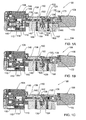
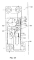
- Figs. 1A-1C are longitudinal cross-sections showing the lock in three operative states: locked state ( Fig. 1A ), intermediate state ( Fig. 1B ), and an unlocked state ( Fig. 1C ).
- the lock 100 shown in Figs. 1A-1C has a housing 102 accommodated within the door 104 and has a first rotating handle assembly 106 at the door's exterior and a second rotating handle assembly 108 at the door's interior.
- the electromagnetic lock 100 includes a bi stable latch solenoid driven mechanism which is operative to switch the lock between the different states and comprises a solenoid 110 with a plunger 112 , associated with a first urging spring 114 and which is axially displaceable between the retracted state of the solenoid shown in Fig. 1A to the extended state shown in Figs. 1B and 1C .
- Plunger 112 has a laterally protruding extension 113 , for the purpose described further below.
- the spring 114 exerts a biasing force on the plunger for displacing the plunger from the retracted to the extended state.
- the lock includes a locking assembly, which can best be seen in Fig. 1E , and includes a lock actuation unit including a distal lock actuation element 120 and a proximal lock actuation element 122 (with respect to the solenoid assembly).
- Actuation element 122 includes a notch 124 which is accommodated within a groove 126 of a rotating cylinder 128 and which is also adapted for engagement with a rotating cam 130 whereupon such engagement cylinder 128 is rotationally coupled to cam 130 .
- Element 122 has a cylindrical body 123 which is fitted within plug 128 and is axially biased in the direction shown by arrow 134 by a third urging spring 136 .
- the locking assembly also includes an auxiliary urging unit formed by a proximal element 138 and a distal one 140 .
- Element 138 fits within cylindrical lumen 142 of plug 144 and has a proximal portion 146 protruding out through opening 148 into the handle assembly 108 .
- Element 140 and element 120 are engaged with one another in a manner best seen in Fig. 1D .
- Each of elements 120 and 140 has a respective hook portion 121 and 141 which are symmetrically identical and are thus adapted for engagement with one another in the manner shown whereby their disengagement from one another is avoided. However, as can be appreciated, such engagement permits movement of the two elements 120 , 140 , one towards the other.
- Hook portions 121 and 141 have a smaller diameter than the main body of elements 120 and 140 whereby a cylindrical circumferential recess is defined accommodating a second urging spring 150 .
- Second urging spring biases the two elements away from one another.
- plug 128 is fitted with ball bearings 160 to permit unhindered rotation of plug 128 within cylindrical lumen 162 of housing 102 .
- Plugs 128 and 144 have respective annular grooves 129 and 145 .
- Pins 164 and 165 which are accommodated within respective bores 166 and 167 , engage with said annular recesses 129 and 145 to fix plug 128 within lumen 162 and plug 144 within lumen 163 .
- Plug 144 is fitted with an engaging element 170 which provides for fixed rotational engagement between plug 144 and rotary cam 130 .
- Plug 128 has an axial protruding element 172 fitting with a recess in handle 106 and fixed through screw 173 .
- Plug 144 has a rear portion 176 to which handle assembly 108 is fitted and fixed through screw 178 .
- Handle assembly 108 also includes a battery and an electric control circuitry, of the general kind known per se, such as that described in US Patent No. 6,865,916 .
- first urging spring 114 is compressed, second urging spring 150 is relatively relaxed and so is third urging spring 136 .
- extension 113 causes axial displacement of elements 138 and 140 towards element 120 giving rise to compression of second urging spring 150, into a state as seen in Fig. 1B .
- the tension energy which is stored in second urging spring 150 causes, in a subsequent step seen in Fig.
- the second spring 150 to axially displace elements 120 and 122 in the same axial direction of the displaced plunger 112 , and consequently, notch 124 being initially in a state in which it is rotationally disengaged from rotary cam 130 , comes into rotary engagement thus yielding a rotational coupling between handle assembly 106 and rotary cam 130 permitting opening of the door from the outside.
- the lock control mechanism is typically programmed to automatic locking after a defined period of time, e.g. 5-10 seconds. Alternatively, this may be through a specific unlocking user inflicting manual command.
- plunger 112 axially moves in the opposite direction from its extended state shown in Fig. 1C into its retracted state as shown in Fig. 1A .
- third urging spring 136 compressed while the lock is in the state of Fig. 1C , can extend moving the lock actuation unit, including elements 124 and 120 , axially into the locked state as seen in Fig. 1A .
- the rotational engagement between plug 128 and rotary cam 130 depends on exact rotational alignment; an intermediate state in which the second urging spring 150 is compressed permits it to store the displacement energy until the proper rotational alignment is achieved whereupon the lock can switch into its locked state.
- the relative strength of the urging springs 114 , 150 and 136 is selected so that in the absence of any magnetic force the force of the uncompressed urging spring 114 is greater than the force of the urging spring 150 in its compressed state.
- the urging spring 150 in its uncompressed state is greater than the strength of the urging spring 136 in its compressed state.
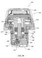
- a rotary lock 200 according to another embodiment not covered by the scope of appended claims is seen in Figs. 2A - 2C in a locked state of the lock ( Fig. 2A ), intermediate state ( Fig. 2B ) and unlocked state ( Fig. 2C ).
- An external prospective view of the cylinder lock can be seen in Fig. 2D .
- Cylinder lock 200 has a housing 202 and a rotational handle assembly 204 .
- Handle assembly 204 forms part of a rotational assembly of the lock generally designated 206 rotational within the housing 202 .
- Handle assembly 204 includes a battery 208 , an electronic circuitry board 210 and a lock control mechanism 212 .
- Latch solenoid 214 is accommodated within the lock and includes a housing 216 , a coil 218 and a fixed magnet 220 , all arranged around a cylindrical lumen 222 accommodating a cylindrical plunger 224 with a laterally protruding head 226 .
- the plunger is associated with a first urging spring 228 .
- the solenoid is typically a bi-stable solenoid of the kind disclosed in US Patent No. 6,865,916 .
- the latch solenoid 214 switches between stables states, including a first, retracted state of the plunger as can be seen in Fig. 2A and a second stable state in which the plunger is extended as can be seen in Figs. 2B and 2C .
- the switch between the state is through an appropriate electrical signal issued by an electronic mechanism incorporated within board 210 .
- Rotational assembly 206 incorporates a locking assembly including a lock actuation member 230 , accommodated within space 232 and an auxiliary actuation member 234 having annular shoulders 236 accommodated within recess 238 .
- Members 230 and 234 can axially displace in a path respectively defined by space 232 and recess 238 .
- Disposed intermediate members 230 and 234 is a second urging spring 240 which imparts a biasing force to force these two members one away from the other.
- Each of members 230 and 234 has a respective tooth portion 231 and 235 providing for engagement of these two members to avoid their axial disengagement from one another and arranged such so as to permit relative axial displacement of these two members towards one another.
- a third urging spring 250 is partially accommodated within a cylindrical lumen 252 or urging element 254 and has its end rested against base element 254 fitted to the housing. Third urging spring 250 thus provides an axial biasing force to resist axial displacement of member 230 in a first axial direction corresponding to the axial displacement of the plunger from its retracted to its extended state.
- Member 230 has a tooth surface 260 adapted for tooth surface 262 of rotary cam 264 , whereupon engagement rotation of rotary assembly 206 causes rotation of rotary cam 264 .
- Rotary cam 264 is engaged with element 266 seen in Fig. 2D , which can then engage the door's dead bolt.
- solenoid 214 Upon issuing of an activation electric signal, in response to an actuation signal from control mechanism 212 , solenoid 214 is activated to displace the plunger 224 from its retracted state as seen in Fig. 2A , in a first axial direction to the extended state as seen in Fig. 2B .
- Such displacement also causes corresponding displacement of member 234 causing compression of second spring 240 which thereby gives rise to an axial biasing force on lock actuation member 230 causing its axial displacement against the biasing force of third urging spring 250 .
- the displacement proceeds until the teeth 260 pressed against teeth 262 of rotary cam 264 .
- rotary handle assembly 206 is rotationally coupled to rotary cam 264 , which is the unlocked state of the lock in which rotation of the handle can open the door permitting access.
- the mechanism is typically designed such that following a defined period of time, e.g. 5-10 seconds similarly as in the case of the embodiment described above, an opposite actuation signal causes the plunger to displace in an opposite axial direction from its extended to its retracted whereupon the biasing force of the third urging spring 250 can cause axial displacement of the entire lock assembly, consisting of member 230 , second urging spring 240 and member 234 in said opposite axial direction to the locked state seen in Fig. 2A .
- the relative strength of the urging springs 228 , 240 and 250 is selected so that in the absence of any magnetic force the force of the uncompressed urging spring 228 is greater than the force of the urging spring 240 in its compressed state.
- the urging spring 240 in its uncompressed state is greater than the strength of the urging spring 250 in its compressed state.
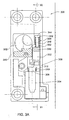
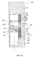
- FIGs. 3A-3C are cross-sectional view in one plane in two different states - a locked state ( Fig. 3A ) and an unlocked state ( Fig. 3B ), while Fig. 3C is a cross-section through a plane normal to that of Fig. 3A along lines III-III of Fig. 3A , showing also the lock in its locked state.
- the compartment lock 300 has a housing 302 accommodating a bi-stable latch solenoid 304 and a locking mechanism generally designated 306 .
- the solenoid 304 includes a plunger 308 associated with a first urging spring 310 .
- the plunger 308 has a head 312 which bears on shoulder 314 of an auxiliary actuation member 316 .
- Second urging arrangement generally designated 318 includes a plunger member 320 having a base 322 and an extended stem 324 of a narrow diameter, fitted in a cylindrical bore of auxiliary actuation member 316 with a second helical spring 326 fitted around stem 324 thereby urging plunger 320 and auxiliary actuation member 316 in opposite axial directions.
- the base 322 of second plunger 320 bears on a lock actuation member 330 having a through bore 332 .
- a third urging arrangement generally designated 340 includes a third plunger 342 having a base 344 bearing against the housing, the intermediate slightly narrower portion 346 and a stem 348 fitting into a bore 350 in actuation member 330 .
- the third urging arrangement also includes a third urging spring 352 bearing at one end at the shoulders formed between intermediate portion 346 and the base 344 and at the other end bears against shoulders defined around the opening of bore 350 .
- auxiliary actuation member 316 is displaced against the biasing force of second helical spring 326 .
- This physical energy stored in the second urging member 326 urges displacement of second plunger 320 thereby displacing lock actuation member 330 into the position as shown in Fig. 3B .
- locking latch 360 which in the locked state shown in Fig. 3A is locked in position, can in the unlocked state shown in Fig. 3B be displaced within the path defined by bore 332 .
- Rotary cam 362 which in the locked state blocks the lateral displacement of a strike (not shown) once in the unlocked state of Fig. 3B rotary cam can rotate thus laterally displacing latch 360 in the direction of arrow 370 which is against the biasing force of the biasing arrangement (not shown).
- the strike When the strike is brought back into position it causes rotation of rotary cam 362 back into the position shown in Fig. 3A whereupon latch 360 comes back into position as a result of the exerted force by its associated urging arrangement (not shown).
- the relative strength of the urging springs 310, 326 and 352 is selected so that in the absence of any magnetic force the force of the uncompressed spring 310 is greater than the force of the urging spring 326 in its compressed state.
- the urging spring 326 in its uncompressed state is greater than the strength of the urging spring 352 in its compressed state.
Landscapes
- Physics & Mathematics (AREA)
- Electromagnetism (AREA)
- Lock And Its Accessories (AREA)
- Electromagnets (AREA)
Claims (8)
- Serrure électromécanique, comprenant :un loquet de verrouillage (360),un ensemble de verrouillage et un solénoïde de verrouillage (304) avec un poussoir (308) déplaçable axialement, par un signal de commande électrique, entre des états rentré et sorti et étant associé à un premier agencement de poussée (310) qui sollicite le poussoir (308) dans une première direction axiale de l'état rentré vers l'état sorti ;l'ensemble de verrouillage comprenant un élément d'actionnement de serrure (330) mobile entre des premier et second états pour verrouiller et déverrouiller la serrure, respectivement, un deuxième agencement de poussée (318) fonctionnant pour solliciter ledit élément d'actionnement de serrure (330) pour se déplacer vers le second état et comprenant un troisième agencement de poussée (340) fonctionnant pour solliciter l'élément d'actionnement de serrure (330) pour se déplacer du second vers le premier état ;le poussoir (308) étant associé fonctionnellement à l'ensemble de verrouillage pour amener ledit élément d'actionnement de serrure (330) à se déplacer du premier au second état pour déverrouiller la serrure lors du déplacement du poussoir (308) dans la première direction, et à permettre le déplacement de l'élément d'actionnement de serrure (330), induit par le troisième agencement de poussée (340), du second vers le premier état pour verrouiller la serrure, lors du déplacement du poussoir (308) de l'état sorti vers l'état rentré,dans laquelle le déplacement de l'élément d'actionnement de serrure (330) du premier état vers le second état crée un trajet permettant le déplacement dudit loquet de verrouillage (360) d'un état engagé vers un état désengagé pour déverrouiller la serrure.
- Serrure électromécanique selon la revendication 1, comprenant :un élément coulissant d'actionnement de serrure (330) mobile par déplacement axial entre des états de verrouillage et de déverrouillage pour verrouiller et déverrouiller la serrure, respectivement, le deuxième agencement de poussée (318) fonctionnant pour solliciter axialement ledit élément d'actionnement de serrure (330) pour se déplacer dans ladite première direction et le troisième agencement de poussée (340) fonctionnant pour solliciter ledit élément d'actionnement de serrure (330) pour se déplacer par déplacement dans une seconde direction opposée à ladite première direction ;le poussoir (308) amenant ledit élément d'actionnement de serrure (330) à se déplacer axialement du premier vers le second état pour déverrouiller la serrure lors du déplacement du poussoir (308) de l'état rentré vers l'état sorti, et à permettre le déplacement axial de l'élément d'actionnement de serrure (330), induit par le troisième agencement de poussée (340), du second vers le premier état pour verrouiller la serrure lors du déplacement du poussoir (308) de l'état sorti vers l'état rentré.
- Serrure électromécanique selon la revendication 1 or 2, dans laquelle ledit deuxième agencement de poussée (318) fonctionne pour exercer une force de sollicitation sur ledit élément d'actionnement de serrure (330) lors du déplacement du poussoir (308) de l'état rentré vers l'état sorti.
- Serrure électromécanique selon la revendication 3, dans laquelle le deuxième agencement de poussée (318) est disposé fonctionnellement entre le poussoir (308) et ledit élément d'actionnement de serrure (330), moyennant quoi, lors du déplacement du poussoir (308) de l'état rentré vers l'état sorti, le poussoir (308) force le deuxième agencement de poussée (318) lequel à son tour sollicite l'élément d'actionnement de serrure (330) pour se déplacer vers ledit second état.
- Serrure électromécanique selon la revendication 3, comprenant :un élément d'actionnement auxiliaire (316) disposé fonctionnellement de manière à s'engager avec le poussoir (308) pour un déplacement axial dans la première direction lors du déplacement du poussoir (308) de l'état rentré vers l'état sorti, le deuxième agencement de poussée (318) étant disposé fonctionnellement entre les deux éléments d'actionnement (316, 330) et les liant l'un à l'autre.
- Serrure électromécanique selon la revendication 5, dans laquelle lors du déplacement du poussoir (308) de l'état rentré vers l'état sorti, l'élément d'actionnement auxiliaire (316) est déplacé dans la première direction, transmettant de l'énergie au deuxième agencement de poussée (318) qui exerce alors une sollicitation sur ledit élément d'actionnement de serrure (330) pour l'amener à se déplacer vers ledit second état.
- Serrure électromécanique selon l'une quelconque des revendications précédentes, dans laquelle la serrure bascule automatiquement de l'état déverrouillé à l'état verrouillé après un laps de temps prédéfini.
- Serrure électromécanique selon l'une quelconque des revendications précédentes, dans laquelle la force de sollicitation du premier agencement de poussée (310) dans son état tendu est supérieure à celle du deuxième agencement de poussée (318) et la force de sollicitation du deuxième agencement de poussée (318) dans son état tendu est supérieure à celle du troisième agencement de poussée (340).
Priority Applications (2)
| Application Number | Priority Date | Filing Date | Title |
|---|---|---|---|
| EP20120195991 EP2570574B1 (fr) | 2007-02-08 | 2008-02-06 | Verrou électromécanique actionné par solénoïde |
| PL08710160T PL2115250T3 (pl) | 2007-02-08 | 2008-02-06 | Zamek elektromechaniczny z solenoidem |
Applications Claiming Priority (2)
| Application Number | Priority Date | Filing Date | Title |
|---|---|---|---|
| US90010107P | 2007-02-08 | 2007-02-08 | |
| PCT/IL2008/000160 WO2008096355A1 (fr) | 2007-02-08 | 2008-02-06 | Verrou électromécanique actionné par solénoïde |
Related Child Applications (2)
| Application Number | Title | Priority Date | Filing Date |
|---|---|---|---|
| EP20120195991 Division EP2570574B1 (fr) | 2007-02-08 | 2008-02-06 | Verrou électromécanique actionné par solénoïde |
| EP12195991.0 Division-Into | 2012-12-07 |
Publications (2)
| Publication Number | Publication Date |
|---|---|
| EP2115250A1 EP2115250A1 (fr) | 2009-11-11 |
| EP2115250B1 true EP2115250B1 (fr) | 2013-08-14 |
Family
ID=39466749
Family Applications (2)
| Application Number | Title | Priority Date | Filing Date |
|---|---|---|---|
| EP20120195991 Not-in-force EP2570574B1 (fr) | 2007-02-08 | 2008-02-06 | Verrou électromécanique actionné par solénoïde |
| EP20080710160 Not-in-force EP2115250B1 (fr) | 2007-02-08 | 2008-02-06 | Verrou électromécanique actionné par solénoïde |
Family Applications Before (1)
| Application Number | Title | Priority Date | Filing Date |
|---|---|---|---|
| EP20120195991 Not-in-force EP2570574B1 (fr) | 2007-02-08 | 2008-02-06 | Verrou électromécanique actionné par solénoïde |
Country Status (6)
| Country | Link |
|---|---|
| US (1) | US8375753B2 (fr) |
| EP (2) | EP2570574B1 (fr) |
| CN (1) | CN101605955B (fr) |
| ES (1) | ES2435193T3 (fr) |
| PL (1) | PL2115250T3 (fr) |
| WO (1) | WO2008096355A1 (fr) |
Families Citing this family (30)
| Publication number | Priority date | Publication date | Assignee | Title |
|---|---|---|---|---|
| BRPI0619822A2 (pt) * | 2005-12-13 | 2011-10-18 | Yebo Tech Proprietary Ltd | sistema eletromecánico de travamento |
| JP5119273B2 (ja) * | 2007-02-21 | 2013-01-16 | アッサ アブロイ アーベー | 施錠装置 |
| JP2013527342A (ja) * | 2009-08-03 | 2013-06-27 | コンビ ロック | ロックアセンブリ |
| EP2529069A1 (fr) * | 2010-01-25 | 2012-12-05 | Knock N'lock Ltd. | Serrure à barillet pour porte |
| EP2365475B1 (fr) * | 2010-03-12 | 2013-05-08 | DESI Alarm ve Güvenlik Sistemleri Sanayi ve Ticaret Ltd. Sti. | Verrou de cylindre électrique |
| US20110225890A1 (en) * | 2010-03-17 | 2011-09-22 | Mark Greenwood | Gate with foot-operated latching mechanism |
| DE202011106208U1 (de) * | 2010-10-01 | 2012-01-12 | Burg-Wächter Kg | Schließzylinder für ein Schloss |
| DE102011102140B4 (de) * | 2011-03-31 | 2013-08-08 | Burg-Wächter Kg | Schließzylinder für ein Schloss |
| US20130335193A1 (en) * | 2011-11-29 | 2013-12-19 | 1556053 Alberta Ltd. | Electronic wireless lock |
| CN102733659B (zh) * | 2012-07-05 | 2015-01-21 | 吴斐 | 一种锁体中的电动旋钮装置 |
| CN104662242A (zh) * | 2012-10-17 | 2015-05-27 | 多尔马德国有限责任公司 | 具有集成的联接装置的门操作件 |
| US9487971B2 (en) * | 2013-03-15 | 2016-11-08 | Spectrum Brands, Inc. | Electro-mechanical locks with bezel turning function |
| CN103206118B (zh) * | 2013-05-04 | 2016-06-15 | 深圳军安信息科技有限公司 | 一种电动锁闭装置 |
| WO2014209217A1 (fr) * | 2013-06-28 | 2014-12-31 | Phoniro Ab | Transmission de verrou de porte électronique |
| US9340998B2 (en) | 2014-02-25 | 2016-05-17 | Schlage Lock Company Llc | Electronic lock with movable in-line locking lug |
| IL232618B (en) | 2014-05-14 | 2018-05-31 | Knock Nlock Ltd | Telescopic lock |
| WO2017006171A2 (fr) * | 2015-07-06 | 2017-01-12 | Acsys Ip Holding Inc. | Systèmes et procédés de sécurisation de systèmes de verrouillage à contrôle d'accès redondant |
| PT3118977T (pt) * | 2015-07-13 | 2019-10-10 | Iloq Oy | Fechadura electromecânica que utiliza forças de campo magnético |
| ES2627477B1 (es) * | 2015-12-28 | 2018-05-08 | Electrobolt Sistemas De Seguridad S.L. | Dispositivo electromagnético de bloqueo accionado a distancia |
| CA3040171A1 (fr) | 2016-10-19 | 2018-04-26 | Dormakaba Usa Inc. | Noyau de verrou electromecanique |
| MX2019010303A (es) * | 2017-04-05 | 2019-10-21 | Dormakaba Canada Inc | Sistema de bloqueo para puerta y conducto de alambre extensible para el mismo. |
| US10344501B2 (en) * | 2017-08-07 | 2019-07-09 | Pamex Inc. | Electronic deadbolt lock |
| ES2927419T3 (es) | 2017-09-08 | 2022-11-07 | Dormakaba Usa Inc | Bombín de cerradura electromecánico |
| CN107956327B (zh) * | 2017-10-25 | 2023-04-07 | 浙江浦江梅花锁业集团有限公司 | 一种锁芯 |
| CN112752891B (zh) | 2018-04-13 | 2022-08-05 | 多玛卡巴美国公司 | 机电锁芯 |
| US11466473B2 (en) | 2018-04-13 | 2022-10-11 | Dormakaba Usa Inc | Electro-mechanical lock core |
| CN108561019B (zh) * | 2018-06-29 | 2024-04-12 | 云南酷联科技有限公司 | 一种锁体离合器及其控制装置 |
| IT201800010405A1 (it) * | 2018-11-16 | 2020-05-16 | Omec Serrature S P A | Cilindro per meccanismi di azionamento |
| SE544858C2 (en) * | 2020-12-22 | 2022-12-13 | Zyax Ab | Locking device with a plunger, a driver and a transmission construction with a central ball and two outer balls and cavities |
| US11961343B2 (en) | 2021-04-13 | 2024-04-16 | D & D Design and Manufacturing, Inc. | Lock |
Family Cites Families (24)
| Publication number | Priority date | Publication date | Assignee | Title |
|---|---|---|---|---|
| CH669425A5 (fr) * | 1985-06-12 | 1989-03-15 | Bauer Kaba Ag | |
| CH668451A5 (de) * | 1985-10-24 | 1988-12-30 | Bauer Kaba Ag | Vorrichtung zur elektromagnetischen verriegelung an einem schliesszylinder fuer ein mechanisch/elektronisches schliess-system. |
| DE3713653A1 (de) * | 1987-04-21 | 1988-11-17 | Zeiss Ikon Ag | Doppelschliesszylinder |
| US5307656A (en) * | 1990-12-17 | 1994-05-03 | La Gard, Inc. | High security electronic dial combination lock |
| IL99716A (en) * | 1991-10-11 | 1996-09-12 | Technolock Engineering | Door locking system |
| US5216909A (en) * | 1992-04-01 | 1993-06-08 | Armoogam Michael A | Electro-mechanical locking mechanism |
| DE19608953A1 (de) | 1996-03-08 | 1997-09-11 | Harting Kgaa | Bistabiler Kleinmagnet |
| FR2749875B1 (fr) | 1996-06-17 | 1999-10-08 | Dawalibi Nofal | Dispositif de verrouillage electronique |
| DE19653525C2 (de) * | 1996-12-20 | 1998-11-05 | Ludwig Hochecker | Schließvorrichtung für ein Schließsystem |
| IL120957A0 (en) * | 1997-03-07 | 1997-09-30 | Goldman Ilan | Code activated system |
| DE19727422C1 (de) * | 1997-06-27 | 1998-06-25 | Meyers Pierre | Koppelsystem für elektronische Verschlußeinrichtungen |
| FR2779168B1 (fr) | 1998-05-27 | 2001-01-26 | Euronetics France | Serrure electronique a embrayage mecanique |
| US5960656A (en) * | 1998-09-02 | 1999-10-05 | Shyang Feng Electric & Machinery Co., Ltd. | Electronic lock |
| EP0999328B1 (fr) * | 1998-11-05 | 2007-01-24 | SimonsVoss Technologies AG | Serrure cylindrique |
| DE19913644C2 (de) * | 1999-03-25 | 2001-02-01 | Sphinx Elektronik Gmbh | Schloß, insbesondere Möbelschloß |
| US6286347B1 (en) * | 1999-08-09 | 2001-09-11 | Harrow Products, Inc. | Clutch mechanism with moveable injector retainer wall for door lock system |
| US6474122B2 (en) * | 2000-01-25 | 2002-11-05 | Videx, Inc. | Electronic locking system |
| US6892557B2 (en) * | 2000-08-22 | 2005-05-17 | Piotr Leonard Kowalczyk | Lock |
| US6581423B2 (en) * | 2001-11-01 | 2003-06-24 | Ching-Tien Lin | Door lock |
| US6865916B2 (en) * | 2002-08-28 | 2005-03-15 | Ilan Goldman | Door cylinder lock |
| US6677844B1 (en) * | 2002-10-21 | 2004-01-13 | Adams Rite Aerospace, Inc. | Quick-return electro-mechanical actuator |
| IL154788A (en) | 2003-03-06 | 2010-12-30 | Goldman Ilan | Electronic locking mechanism and lock containing it |
| CN2687248Y (zh) * | 2004-04-09 | 2005-03-23 | 上海欧一安保器材有限公司 | 一种改良的电磁锁 |
| US7784315B2 (en) * | 2007-07-20 | 2010-08-31 | Ping-Jan Yang | Locking device for truck |
-
2008
- 2008-02-06 WO PCT/IL2008/000160 patent/WO2008096355A1/fr active Application Filing
- 2008-02-06 PL PL08710160T patent/PL2115250T3/pl unknown
- 2008-02-06 ES ES08710160T patent/ES2435193T3/es active Active
- 2008-02-06 EP EP20120195991 patent/EP2570574B1/fr not_active Not-in-force
- 2008-02-06 CN CN2008800044341A patent/CN101605955B/zh not_active Expired - Fee Related
- 2008-02-06 US US12/449,356 patent/US8375753B2/en not_active Expired - Fee Related
- 2008-02-06 EP EP20080710160 patent/EP2115250B1/fr not_active Not-in-force
Also Published As
| Publication number | Publication date |
|---|---|
| EP2115250A1 (fr) | 2009-11-11 |
| CN101605955B (zh) | 2013-07-10 |
| ES2435193T3 (es) | 2013-12-16 |
| WO2008096355A1 (fr) | 2008-08-14 |
| EP2570574A1 (fr) | 2013-03-20 |
| US8375753B2 (en) | 2013-02-19 |
| PL2115250T3 (pl) | 2014-02-28 |
| CN101605955A (zh) | 2009-12-16 |
| US20090308117A1 (en) | 2009-12-17 |
| EP2570574B1 (fr) | 2014-09-17 |
Similar Documents
| Publication | Publication Date | Title |
|---|---|---|
| EP2115250B1 (fr) | Verrou électromécanique actionné par solénoïde | |
| DK1490571T3 (en) | Electronic locking system with emergency output function. | |
| JP3537834B2 (ja) | ロック装置 | |
| EP1543208B1 (fr) | Dispositif de verrouillage de porte | |
| EP1366255B1 (fr) | Systeme de verrouillage electronique | |
| US5953942A (en) | Catch mechanism for locks | |
| US8001818B2 (en) | Clutch mechanism couplable to door locks with locking bolt operated by handles or knobs | |
| EP1250505B1 (fr) | Systeme de verrouillage electronique | |
| JP2006511738A (ja) | 施錠装置 | |
| US20130152646A1 (en) | Electromechanical cylinder lock | |
| US20080196457A1 (en) | Combination lock with light indicators | |
| WO2000052284A1 (fr) | Appareil et dispositif pour verrou electronique | |
| US6094953A (en) | Electrically controlled slidebolt lock | |
| EP3299553B1 (fr) | Dispositif de poignée | |
| WO2012102633A1 (fr) | Serrure électronique avec moyen de blocage passif | |
| RU2656790C1 (ru) | Электронный цилиндр для замка | |
| RU2783155C1 (ru) | Электромеханическое замковое устройство | |
| CN112955618B (zh) | 用于驱动机构的锁头 | |
| AU2022400246A1 (en) | Locking device for a closure element | |
| AU2022399944A1 (en) | Electromechanical locking device | |
| AU2003253246B2 (en) | Door cylinder lock | |
| JP2022020904A (ja) | 電気錠 |
Legal Events
| Date | Code | Title | Description |
|---|---|---|---|
| PUAI | Public reference made under article 153(3) epc to a published international application that has entered the european phase |
Free format text: ORIGINAL CODE: 0009012 |
|
| 17P | Request for examination filed |
Effective date: 20090810 |
|
| AK | Designated contracting states |
Kind code of ref document: A1 Designated state(s): AT BE BG CH CY CZ DE DK EE ES FI FR GB GR HR HU IE IS IT LI LT LU LV MC MT NL NO PL PT RO SE SI SK TR |
|
| DAX | Request for extension of the european patent (deleted) | ||
| 17Q | First examination report despatched |
Effective date: 20101208 |
|
| RIN1 | Information on inventor provided before grant (corrected) |
Inventor name: GOLDMAN, ILAN |
|
| GRAP | Despatch of communication of intention to grant a patent |
Free format text: ORIGINAL CODE: EPIDOSNIGR1 |
|
| GRAS | Grant fee paid |
Free format text: ORIGINAL CODE: EPIDOSNIGR3 |
|
| GRAA | (expected) grant |
Free format text: ORIGINAL CODE: 0009210 |
|
| AK | Designated contracting states |
Kind code of ref document: B1 Designated state(s): AT BE BG CH CY CZ DE DK EE ES FI FR GB GR HR HU IE IS IT LI LT LU LV MC MT NL NO PL PT RO SE SI SK TR |
|
| REG | Reference to a national code |
Ref country code: GB Ref legal event code: FG4D |
|
| REG | Reference to a national code |
Ref country code: CH Ref legal event code: EP Ref country code: AT Ref legal event code: REF Ref document number: 626988 Country of ref document: AT Kind code of ref document: T Effective date: 20130815 |
|
| REG | Reference to a national code |
Ref country code: IE Ref legal event code: FG4D |
|
| REG | Reference to a national code |
Ref country code: DE Ref legal event code: R096 Ref document number: 602008026749 Country of ref document: DE Effective date: 20131010 |
|
| REG | Reference to a national code |
Ref country code: SE Ref legal event code: TRGR |
|
| REG | Reference to a national code |
Ref country code: NL Ref legal event code: T3 |
|
| REG | Reference to a national code |
Ref country code: CH Ref legal event code: NV Representative=s name: MARKS AND CLERK (LUXEMBOURG) LLP, CH |
|
| REG | Reference to a national code |
Ref country code: ES Ref legal event code: FG2A Ref document number: 2435193 Country of ref document: ES Kind code of ref document: T3 Effective date: 20131216 |
|
| REG | Reference to a national code |
Ref country code: LT Ref legal event code: MG4D |
|
| PG25 | Lapsed in a contracting state [announced via postgrant information from national office to epo] |
Ref country code: NO Free format text: LAPSE BECAUSE OF FAILURE TO SUBMIT A TRANSLATION OF THE DESCRIPTION OR TO PAY THE FEE WITHIN THE PRESCRIBED TIME-LIMIT Effective date: 20131114 Ref country code: IS Free format text: LAPSE BECAUSE OF FAILURE TO SUBMIT A TRANSLATION OF THE DESCRIPTION OR TO PAY THE FEE WITHIN THE PRESCRIBED TIME-LIMIT Effective date: 20131214 Ref country code: LT Free format text: LAPSE BECAUSE OF FAILURE TO SUBMIT A TRANSLATION OF THE DESCRIPTION OR TO PAY THE FEE WITHIN THE PRESCRIBED TIME-LIMIT Effective date: 20130814 Ref country code: CY Free format text: LAPSE BECAUSE OF FAILURE TO SUBMIT A TRANSLATION OF THE DESCRIPTION OR TO PAY THE FEE WITHIN THE PRESCRIBED TIME-LIMIT Effective date: 20130814 Ref country code: HR Free format text: LAPSE BECAUSE OF FAILURE TO SUBMIT A TRANSLATION OF THE DESCRIPTION OR TO PAY THE FEE WITHIN THE PRESCRIBED TIME-LIMIT Effective date: 20130814 Ref country code: PT Free format text: LAPSE BECAUSE OF FAILURE TO SUBMIT A TRANSLATION OF THE DESCRIPTION OR TO PAY THE FEE WITHIN THE PRESCRIBED TIME-LIMIT Effective date: 20131216 |
|
| PG25 | Lapsed in a contracting state [announced via postgrant information from national office to epo] |
Ref country code: BE Free format text: LAPSE BECAUSE OF FAILURE TO SUBMIT A TRANSLATION OF THE DESCRIPTION OR TO PAY THE FEE WITHIN THE PRESCRIBED TIME-LIMIT Effective date: 20130814 Ref country code: SI Free format text: LAPSE BECAUSE OF FAILURE TO SUBMIT A TRANSLATION OF THE DESCRIPTION OR TO PAY THE FEE WITHIN THE PRESCRIBED TIME-LIMIT Effective date: 20130814 Ref country code: GR Free format text: LAPSE BECAUSE OF FAILURE TO SUBMIT A TRANSLATION OF THE DESCRIPTION OR TO PAY THE FEE WITHIN THE PRESCRIBED TIME-LIMIT Effective date: 20131115 Ref country code: LV Free format text: LAPSE BECAUSE OF FAILURE TO SUBMIT A TRANSLATION OF THE DESCRIPTION OR TO PAY THE FEE WITHIN THE PRESCRIBED TIME-LIMIT Effective date: 20130814 |
|
| REG | Reference to a national code |
Ref country code: PL Ref legal event code: T3 |
|
| PG25 | Lapsed in a contracting state [announced via postgrant information from national office to epo] |
Ref country code: DK Free format text: LAPSE BECAUSE OF FAILURE TO SUBMIT A TRANSLATION OF THE DESCRIPTION OR TO PAY THE FEE WITHIN THE PRESCRIBED TIME-LIMIT Effective date: 20130814 Ref country code: RO Free format text: LAPSE BECAUSE OF FAILURE TO SUBMIT A TRANSLATION OF THE DESCRIPTION OR TO PAY THE FEE WITHIN THE PRESCRIBED TIME-LIMIT Effective date: 20130814 Ref country code: SK Free format text: LAPSE BECAUSE OF FAILURE TO SUBMIT A TRANSLATION OF THE DESCRIPTION OR TO PAY THE FEE WITHIN THE PRESCRIBED TIME-LIMIT Effective date: 20130814 Ref country code: EE Free format text: LAPSE BECAUSE OF FAILURE TO SUBMIT A TRANSLATION OF THE DESCRIPTION OR TO PAY THE FEE WITHIN THE PRESCRIBED TIME-LIMIT Effective date: 20130814 |
|
| PGFP | Annual fee paid to national office [announced via postgrant information from national office to epo] |
Ref country code: SE Payment date: 20140226 Year of fee payment: 7 Ref country code: NL Payment date: 20140224 Year of fee payment: 7 Ref country code: CH Payment date: 20140225 Year of fee payment: 7 Ref country code: FI Payment date: 20140224 Year of fee payment: 7 Ref country code: CZ Payment date: 20140131 Year of fee payment: 7 |
|
| PGFP | Annual fee paid to national office [announced via postgrant information from national office to epo] |
Ref country code: FR Payment date: 20140226 Year of fee payment: 7 Ref country code: ES Payment date: 20140321 Year of fee payment: 7 Ref country code: IT Payment date: 20140220 Year of fee payment: 7 Ref country code: PL Payment date: 20140204 Year of fee payment: 7 Ref country code: TR Payment date: 20140127 Year of fee payment: 7 Ref country code: AT Payment date: 20140228 Year of fee payment: 7 |
|
| PLBE | No opposition filed within time limit |
Free format text: ORIGINAL CODE: 0009261 |
|
| STAA | Information on the status of an ep patent application or granted ep patent |
Free format text: STATUS: NO OPPOSITION FILED WITHIN TIME LIMIT |
|
| PGFP | Annual fee paid to national office [announced via postgrant information from national office to epo] |
Ref country code: GB Payment date: 20140228 Year of fee payment: 7 |
|
| 26N | No opposition filed |
Effective date: 20140515 |
|
| REG | Reference to a national code |
Ref country code: DE Ref legal event code: R097 Ref document number: 602008026749 Country of ref document: DE Effective date: 20140515 |
|
| PGFP | Annual fee paid to national office [announced via postgrant information from national office to epo] |
Ref country code: DE Payment date: 20140430 Year of fee payment: 7 |
|
| PG25 | Lapsed in a contracting state [announced via postgrant information from national office to epo] |
Ref country code: MC Free format text: LAPSE BECAUSE OF FAILURE TO SUBMIT A TRANSLATION OF THE DESCRIPTION OR TO PAY THE FEE WITHIN THE PRESCRIBED TIME-LIMIT Effective date: 20130814 Ref country code: LU Free format text: LAPSE BECAUSE OF FAILURE TO SUBMIT A TRANSLATION OF THE DESCRIPTION OR TO PAY THE FEE WITHIN THE PRESCRIBED TIME-LIMIT Effective date: 20140206 |
|
| REG | Reference to a national code |
Ref country code: IE Ref legal event code: MM4A |
|
| PG25 | Lapsed in a contracting state [announced via postgrant information from national office to epo] |
Ref country code: IE Free format text: LAPSE BECAUSE OF NON-PAYMENT OF DUE FEES Effective date: 20140206 |
|
| REG | Reference to a national code |
Ref country code: DE Ref legal event code: R119 Ref document number: 602008026749 Country of ref document: DE |
|
| REG | Reference to a national code |
Ref country code: NL Ref legal event code: V1 Effective date: 20150901 |
|
| REG | Reference to a national code |
Ref country code: SE Ref legal event code: EUG |
|
| PG25 | Lapsed in a contracting state [announced via postgrant information from national office to epo] |
Ref country code: NL Free format text: LAPSE BECAUSE OF NON-PAYMENT OF DUE FEES Effective date: 20150901 |
|
| REG | Reference to a national code |
Ref country code: CH Ref legal event code: PL |
|
| REG | Reference to a national code |
Ref country code: AT Ref legal event code: MM01 Ref document number: 626988 Country of ref document: AT Kind code of ref document: T Effective date: 20150206 |
|
| GBPC | Gb: european patent ceased through non-payment of renewal fee |
Effective date: 20150206 |
|
| PG25 | Lapsed in a contracting state [announced via postgrant information from national office to epo] |
Ref country code: CZ Free format text: LAPSE BECAUSE OF NON-PAYMENT OF DUE FEES Effective date: 20150206 Ref country code: CH Free format text: LAPSE BECAUSE OF NON-PAYMENT OF DUE FEES Effective date: 20150228 Ref country code: FI Free format text: LAPSE BECAUSE OF NON-PAYMENT OF DUE FEES Effective date: 20150206 Ref country code: LI Free format text: LAPSE BECAUSE OF NON-PAYMENT OF DUE FEES Effective date: 20150228 |
|
| REG | Reference to a national code |
Ref country code: FR Ref legal event code: ST Effective date: 20151030 |
|
| PG25 | Lapsed in a contracting state [announced via postgrant information from national office to epo] |
Ref country code: SE Free format text: LAPSE BECAUSE OF NON-PAYMENT OF DUE FEES Effective date: 20150207 Ref country code: AT Free format text: LAPSE BECAUSE OF NON-PAYMENT OF DUE FEES Effective date: 20150206 |
|
| PG25 | Lapsed in a contracting state [announced via postgrant information from national office to epo] |
Ref country code: IT Free format text: LAPSE BECAUSE OF NON-PAYMENT OF DUE FEES Effective date: 20150206 |
|
| PG25 | Lapsed in a contracting state [announced via postgrant information from national office to epo] |
Ref country code: DE Free format text: LAPSE BECAUSE OF NON-PAYMENT OF DUE FEES Effective date: 20150901 Ref country code: GB Free format text: LAPSE BECAUSE OF NON-PAYMENT OF DUE FEES Effective date: 20150206 |
|
| PG25 | Lapsed in a contracting state [announced via postgrant information from national office to epo] |
Ref country code: FR Free format text: LAPSE BECAUSE OF NON-PAYMENT OF DUE FEES Effective date: 20150302 Ref country code: MT Free format text: LAPSE BECAUSE OF FAILURE TO SUBMIT A TRANSLATION OF THE DESCRIPTION OR TO PAY THE FEE WITHIN THE PRESCRIBED TIME-LIMIT Effective date: 20130814 |
|
| REG | Reference to a national code |
Ref country code: ES Ref legal event code: FD2A Effective date: 20160329 |
|
| PG25 | Lapsed in a contracting state [announced via postgrant information from national office to epo] |
Ref country code: ES Free format text: LAPSE BECAUSE OF NON-PAYMENT OF DUE FEES Effective date: 20150207 |
|
| PG25 | Lapsed in a contracting state [announced via postgrant information from national office to epo] |
Ref country code: PL Free format text: LAPSE BECAUSE OF NON-PAYMENT OF DUE FEES Effective date: 20150206 Ref country code: BG Free format text: LAPSE BECAUSE OF FAILURE TO SUBMIT A TRANSLATION OF THE DESCRIPTION OR TO PAY THE FEE WITHIN THE PRESCRIBED TIME-LIMIT Effective date: 20130814 |
|
| PG25 | Lapsed in a contracting state [announced via postgrant information from national office to epo] |
Ref country code: HU Free format text: LAPSE BECAUSE OF FAILURE TO SUBMIT A TRANSLATION OF THE DESCRIPTION OR TO PAY THE FEE WITHIN THE PRESCRIBED TIME-LIMIT; INVALID AB INITIO Effective date: 20080206 |
|
| PG25 | Lapsed in a contracting state [announced via postgrant information from national office to epo] |
Ref country code: TR Free format text: LAPSE BECAUSE OF NON-PAYMENT OF DUE FEES Effective date: 20150206 |