EP2114714B1 - Control system and hybrid vehicles with reconfigurable multi-function power converter - Google Patents
Control system and hybrid vehicles with reconfigurable multi-function power converter Download PDFInfo
- Publication number
- EP2114714B1 EP2114714B1 EP08729474.0A EP08729474A EP2114714B1 EP 2114714 B1 EP2114714 B1 EP 2114714B1 EP 08729474 A EP08729474 A EP 08729474A EP 2114714 B1 EP2114714 B1 EP 2114714B1
- Authority
- EP
- European Patent Office
- Prior art keywords
- energy storage
- storage device
- power
- power converter
- drive system
- Prior art date
- Legal status (The legal status is an assumption and is not a legal conclusion. Google has not performed a legal analysis and makes no representation as to the accuracy of the status listed.)
- Active
Links
- 238000004146 energy storage Methods 0.000 claims description 74
- 238000006243 chemical reaction Methods 0.000 claims description 16
- 238000000034 method Methods 0.000 description 13
- 230000001360 synchronised effect Effects 0.000 description 7
- 238000010586 diagram Methods 0.000 description 6
- 238000002485 combustion reaction Methods 0.000 description 5
- 239000003054 catalyst Substances 0.000 description 3
- 238000010248 power generation Methods 0.000 description 3
- HBBGRARXTFLTSG-UHFFFAOYSA-N Lithium ion Chemical compound [Li+] HBBGRARXTFLTSG-UHFFFAOYSA-N 0.000 description 2
- 230000005611 electricity Effects 0.000 description 2
- 229910001416 lithium ion Inorganic materials 0.000 description 2
- 230000000737 periodic effect Effects 0.000 description 2
- 101100206458 Mus musculus Them4 gene Proteins 0.000 description 1
- 230000004913 activation Effects 0.000 description 1
- 239000003990 capacitor Substances 0.000 description 1
- 230000005669 field effect Effects 0.000 description 1
- 230000010354 integration Effects 0.000 description 1
- 238000004519 manufacturing process Methods 0.000 description 1
- 229910052987 metal hydride Inorganic materials 0.000 description 1
- 229910044991 metal oxide Inorganic materials 0.000 description 1
- 150000004706 metal oxides Chemical class 0.000 description 1
- 238000012986 modification Methods 0.000 description 1
- 230000004048 modification Effects 0.000 description 1
- YBGGBHCJSAEIAS-UHFFFAOYSA-N n-[5-[2-(2,6-dichlorophenyl)-5-(difluoromethyl)pyrazol-3-yl]-1,3-thiazol-2-yl]cyclopropanecarboxamide Chemical compound ClC=1C=CC=C(Cl)C=1N1N=C(C(F)F)C=C1C(S1)=CN=C1NC(=O)C1CC1 YBGGBHCJSAEIAS-UHFFFAOYSA-N 0.000 description 1
- 229910052759 nickel Inorganic materials 0.000 description 1
- PXHVJJICTQNCMI-UHFFFAOYSA-N nickel Substances [Ni] PXHVJJICTQNCMI-UHFFFAOYSA-N 0.000 description 1
- -1 nickel metal hydride Chemical class 0.000 description 1
- 239000004065 semiconductor Substances 0.000 description 1
- 238000010792 warming Methods 0.000 description 1
Images


Classifications
-
- B—PERFORMING OPERATIONS; TRANSPORTING
- B60—VEHICLES IN GENERAL
- B60K—ARRANGEMENT OR MOUNTING OF PROPULSION UNITS OR OF TRANSMISSIONS IN VEHICLES; ARRANGEMENT OR MOUNTING OF PLURAL DIVERSE PRIME-MOVERS IN VEHICLES; AUXILIARY DRIVES FOR VEHICLES; INSTRUMENTATION OR DASHBOARDS FOR VEHICLES; ARRANGEMENTS IN CONNECTION WITH COOLING, AIR INTAKE, GAS EXHAUST OR FUEL SUPPLY OF PROPULSION UNITS IN VEHICLES
- B60K1/00—Arrangement or mounting of electrical propulsion units
-
- B—PERFORMING OPERATIONS; TRANSPORTING
- B60—VEHICLES IN GENERAL
- B60L—PROPULSION OF ELECTRICALLY-PROPELLED VEHICLES; SUPPLYING ELECTRIC POWER FOR AUXILIARY EQUIPMENT OF ELECTRICALLY-PROPELLED VEHICLES; ELECTRODYNAMIC BRAKE SYSTEMS FOR VEHICLES IN GENERAL; MAGNETIC SUSPENSION OR LEVITATION FOR VEHICLES; MONITORING OPERATING VARIABLES OF ELECTRICALLY-PROPELLED VEHICLES; ELECTRIC SAFETY DEVICES FOR ELECTRICALLY-PROPELLED VEHICLES
- B60L53/00—Methods of charging batteries, specially adapted for electric vehicles; Charging stations or on-board charging equipment therefor; Exchange of energy storage elements in electric vehicles
- B60L53/10—Methods of charging batteries, specially adapted for electric vehicles; Charging stations or on-board charging equipment therefor; Exchange of energy storage elements in electric vehicles characterised by the energy transfer between the charging station and the vehicle
- B60L53/14—Conductive energy transfer
-
- B—PERFORMING OPERATIONS; TRANSPORTING
- B60—VEHICLES IN GENERAL
- B60L—PROPULSION OF ELECTRICALLY-PROPELLED VEHICLES; SUPPLYING ELECTRIC POWER FOR AUXILIARY EQUIPMENT OF ELECTRICALLY-PROPELLED VEHICLES; ELECTRODYNAMIC BRAKE SYSTEMS FOR VEHICLES IN GENERAL; MAGNETIC SUSPENSION OR LEVITATION FOR VEHICLES; MONITORING OPERATING VARIABLES OF ELECTRICALLY-PROPELLED VEHICLES; ELECTRIC SAFETY DEVICES FOR ELECTRICALLY-PROPELLED VEHICLES
- B60L50/00—Electric propulsion with power supplied within the vehicle
- B60L50/10—Electric propulsion with power supplied within the vehicle using propulsion power supplied by engine-driven generators, e.g. generators driven by combustion engines
- B60L50/16—Electric propulsion with power supplied within the vehicle using propulsion power supplied by engine-driven generators, e.g. generators driven by combustion engines with provision for separate direct mechanical propulsion
-
- B—PERFORMING OPERATIONS; TRANSPORTING
- B60—VEHICLES IN GENERAL
- B60L—PROPULSION OF ELECTRICALLY-PROPELLED VEHICLES; SUPPLYING ELECTRIC POWER FOR AUXILIARY EQUIPMENT OF ELECTRICALLY-PROPELLED VEHICLES; ELECTRODYNAMIC BRAKE SYSTEMS FOR VEHICLES IN GENERAL; MAGNETIC SUSPENSION OR LEVITATION FOR VEHICLES; MONITORING OPERATING VARIABLES OF ELECTRICALLY-PROPELLED VEHICLES; ELECTRIC SAFETY DEVICES FOR ELECTRICALLY-PROPELLED VEHICLES
- B60L50/00—Electric propulsion with power supplied within the vehicle
- B60L50/50—Electric propulsion with power supplied within the vehicle using propulsion power supplied by batteries or fuel cells
-
- B—PERFORMING OPERATIONS; TRANSPORTING
- B60—VEHICLES IN GENERAL
- B60L—PROPULSION OF ELECTRICALLY-PROPELLED VEHICLES; SUPPLYING ELECTRIC POWER FOR AUXILIARY EQUIPMENT OF ELECTRICALLY-PROPELLED VEHICLES; ELECTRODYNAMIC BRAKE SYSTEMS FOR VEHICLES IN GENERAL; MAGNETIC SUSPENSION OR LEVITATION FOR VEHICLES; MONITORING OPERATING VARIABLES OF ELECTRICALLY-PROPELLED VEHICLES; ELECTRIC SAFETY DEVICES FOR ELECTRICALLY-PROPELLED VEHICLES
- B60L58/00—Methods or circuit arrangements for monitoring or controlling batteries or fuel cells, specially adapted for electric vehicles
- B60L58/10—Methods or circuit arrangements for monitoring or controlling batteries or fuel cells, specially adapted for electric vehicles for monitoring or controlling batteries
- B60L58/18—Methods or circuit arrangements for monitoring or controlling batteries or fuel cells, specially adapted for electric vehicles for monitoring or controlling batteries of two or more battery modules
- B60L58/20—Methods or circuit arrangements for monitoring or controlling batteries or fuel cells, specially adapted for electric vehicles for monitoring or controlling batteries of two or more battery modules having different nominal voltages
-
- B—PERFORMING OPERATIONS; TRANSPORTING
- B60—VEHICLES IN GENERAL
- B60L—PROPULSION OF ELECTRICALLY-PROPELLED VEHICLES; SUPPLYING ELECTRIC POWER FOR AUXILIARY EQUIPMENT OF ELECTRICALLY-PROPELLED VEHICLES; ELECTRODYNAMIC BRAKE SYSTEMS FOR VEHICLES IN GENERAL; MAGNETIC SUSPENSION OR LEVITATION FOR VEHICLES; MONITORING OPERATING VARIABLES OF ELECTRICALLY-PROPELLED VEHICLES; ELECTRIC SAFETY DEVICES FOR ELECTRICALLY-PROPELLED VEHICLES
- B60L58/00—Methods or circuit arrangements for monitoring or controlling batteries or fuel cells, specially adapted for electric vehicles
- B60L58/10—Methods or circuit arrangements for monitoring or controlling batteries or fuel cells, specially adapted for electric vehicles for monitoring or controlling batteries
- B60L58/18—Methods or circuit arrangements for monitoring or controlling batteries or fuel cells, specially adapted for electric vehicles for monitoring or controlling batteries of two or more battery modules
- B60L58/21—Methods or circuit arrangements for monitoring or controlling batteries or fuel cells, specially adapted for electric vehicles for monitoring or controlling batteries of two or more battery modules having the same nominal voltage
-
- B—PERFORMING OPERATIONS; TRANSPORTING
- B60—VEHICLES IN GENERAL
- B60W—CONJOINT CONTROL OF VEHICLE SUB-UNITS OF DIFFERENT TYPE OR DIFFERENT FUNCTION; CONTROL SYSTEMS SPECIALLY ADAPTED FOR HYBRID VEHICLES; ROAD VEHICLE DRIVE CONTROL SYSTEMS FOR PURPOSES NOT RELATED TO THE CONTROL OF A PARTICULAR SUB-UNIT
- B60W10/00—Conjoint control of vehicle sub-units of different type or different function
- B60W10/24—Conjoint control of vehicle sub-units of different type or different function including control of energy storage means
- B60W10/26—Conjoint control of vehicle sub-units of different type or different function including control of energy storage means for electrical energy, e.g. batteries or capacitors
-
- B—PERFORMING OPERATIONS; TRANSPORTING
- B60—VEHICLES IN GENERAL
- B60W—CONJOINT CONTROL OF VEHICLE SUB-UNITS OF DIFFERENT TYPE OR DIFFERENT FUNCTION; CONTROL SYSTEMS SPECIALLY ADAPTED FOR HYBRID VEHICLES; ROAD VEHICLE DRIVE CONTROL SYSTEMS FOR PURPOSES NOT RELATED TO THE CONTROL OF A PARTICULAR SUB-UNIT
- B60W20/00—Control systems specially adapted for hybrid vehicles
- B60W20/10—Controlling the power contribution of each of the prime movers to meet required power demand
-
- B—PERFORMING OPERATIONS; TRANSPORTING
- B60—VEHICLES IN GENERAL
- B60L—PROPULSION OF ELECTRICALLY-PROPELLED VEHICLES; SUPPLYING ELECTRIC POWER FOR AUXILIARY EQUIPMENT OF ELECTRICALLY-PROPELLED VEHICLES; ELECTRODYNAMIC BRAKE SYSTEMS FOR VEHICLES IN GENERAL; MAGNETIC SUSPENSION OR LEVITATION FOR VEHICLES; MONITORING OPERATING VARIABLES OF ELECTRICALLY-PROPELLED VEHICLES; ELECTRIC SAFETY DEVICES FOR ELECTRICALLY-PROPELLED VEHICLES
- B60L2210/00—Converter types
- B60L2210/10—DC to DC converters
- B60L2210/12—Buck converters
-
- B—PERFORMING OPERATIONS; TRANSPORTING
- B60—VEHICLES IN GENERAL
- B60L—PROPULSION OF ELECTRICALLY-PROPELLED VEHICLES; SUPPLYING ELECTRIC POWER FOR AUXILIARY EQUIPMENT OF ELECTRICALLY-PROPELLED VEHICLES; ELECTRODYNAMIC BRAKE SYSTEMS FOR VEHICLES IN GENERAL; MAGNETIC SUSPENSION OR LEVITATION FOR VEHICLES; MONITORING OPERATING VARIABLES OF ELECTRICALLY-PROPELLED VEHICLES; ELECTRIC SAFETY DEVICES FOR ELECTRICALLY-PROPELLED VEHICLES
- B60L2210/00—Converter types
- B60L2210/10—DC to DC converters
- B60L2210/14—Boost converters
-
- B—PERFORMING OPERATIONS; TRANSPORTING
- B60—VEHICLES IN GENERAL
- B60L—PROPULSION OF ELECTRICALLY-PROPELLED VEHICLES; SUPPLYING ELECTRIC POWER FOR AUXILIARY EQUIPMENT OF ELECTRICALLY-PROPELLED VEHICLES; ELECTRODYNAMIC BRAKE SYSTEMS FOR VEHICLES IN GENERAL; MAGNETIC SUSPENSION OR LEVITATION FOR VEHICLES; MONITORING OPERATING VARIABLES OF ELECTRICALLY-PROPELLED VEHICLES; ELECTRIC SAFETY DEVICES FOR ELECTRICALLY-PROPELLED VEHICLES
- B60L2210/00—Converter types
- B60L2210/20—AC to AC converters
-
- B—PERFORMING OPERATIONS; TRANSPORTING
- B60—VEHICLES IN GENERAL
- B60L—PROPULSION OF ELECTRICALLY-PROPELLED VEHICLES; SUPPLYING ELECTRIC POWER FOR AUXILIARY EQUIPMENT OF ELECTRICALLY-PROPELLED VEHICLES; ELECTRODYNAMIC BRAKE SYSTEMS FOR VEHICLES IN GENERAL; MAGNETIC SUSPENSION OR LEVITATION FOR VEHICLES; MONITORING OPERATING VARIABLES OF ELECTRICALLY-PROPELLED VEHICLES; ELECTRIC SAFETY DEVICES FOR ELECTRICALLY-PROPELLED VEHICLES
- B60L2210/00—Converter types
- B60L2210/30—AC to DC converters
-
- B—PERFORMING OPERATIONS; TRANSPORTING
- B60—VEHICLES IN GENERAL
- B60L—PROPULSION OF ELECTRICALLY-PROPELLED VEHICLES; SUPPLYING ELECTRIC POWER FOR AUXILIARY EQUIPMENT OF ELECTRICALLY-PROPELLED VEHICLES; ELECTRODYNAMIC BRAKE SYSTEMS FOR VEHICLES IN GENERAL; MAGNETIC SUSPENSION OR LEVITATION FOR VEHICLES; MONITORING OPERATING VARIABLES OF ELECTRICALLY-PROPELLED VEHICLES; ELECTRIC SAFETY DEVICES FOR ELECTRICALLY-PROPELLED VEHICLES
- B60L2240/00—Control parameters of input or output; Target parameters
- B60L2240/40—Drive Train control parameters
- B60L2240/54—Drive Train control parameters related to batteries
- B60L2240/545—Temperature
-
- B—PERFORMING OPERATIONS; TRANSPORTING
- B60—VEHICLES IN GENERAL
- B60L—PROPULSION OF ELECTRICALLY-PROPELLED VEHICLES; SUPPLYING ELECTRIC POWER FOR AUXILIARY EQUIPMENT OF ELECTRICALLY-PROPELLED VEHICLES; ELECTRODYNAMIC BRAKE SYSTEMS FOR VEHICLES IN GENERAL; MAGNETIC SUSPENSION OR LEVITATION FOR VEHICLES; MONITORING OPERATING VARIABLES OF ELECTRICALLY-PROPELLED VEHICLES; ELECTRIC SAFETY DEVICES FOR ELECTRICALLY-PROPELLED VEHICLES
- B60L2240/00—Control parameters of input or output; Target parameters
- B60L2240/40—Drive Train control parameters
- B60L2240/54—Drive Train control parameters related to batteries
- B60L2240/547—Voltage
-
- B—PERFORMING OPERATIONS; TRANSPORTING
- B60—VEHICLES IN GENERAL
- B60L—PROPULSION OF ELECTRICALLY-PROPELLED VEHICLES; SUPPLYING ELECTRIC POWER FOR AUXILIARY EQUIPMENT OF ELECTRICALLY-PROPELLED VEHICLES; ELECTRODYNAMIC BRAKE SYSTEMS FOR VEHICLES IN GENERAL; MAGNETIC SUSPENSION OR LEVITATION FOR VEHICLES; MONITORING OPERATING VARIABLES OF ELECTRICALLY-PROPELLED VEHICLES; ELECTRIC SAFETY DEVICES FOR ELECTRICALLY-PROPELLED VEHICLES
- B60L2240/00—Control parameters of input or output; Target parameters
- B60L2240/40—Drive Train control parameters
- B60L2240/54—Drive Train control parameters related to batteries
- B60L2240/549—Current
-
- B—PERFORMING OPERATIONS; TRANSPORTING
- B60—VEHICLES IN GENERAL
- B60W—CONJOINT CONTROL OF VEHICLE SUB-UNITS OF DIFFERENT TYPE OR DIFFERENT FUNCTION; CONTROL SYSTEMS SPECIALLY ADAPTED FOR HYBRID VEHICLES; ROAD VEHICLE DRIVE CONTROL SYSTEMS FOR PURPOSES NOT RELATED TO THE CONTROL OF A PARTICULAR SUB-UNIT
- B60W20/00—Control systems specially adapted for hybrid vehicles
-
- B—PERFORMING OPERATIONS; TRANSPORTING
- B60—VEHICLES IN GENERAL
- B60W—CONJOINT CONTROL OF VEHICLE SUB-UNITS OF DIFFERENT TYPE OR DIFFERENT FUNCTION; CONTROL SYSTEMS SPECIALLY ADAPTED FOR HYBRID VEHICLES; ROAD VEHICLE DRIVE CONTROL SYSTEMS FOR PURPOSES NOT RELATED TO THE CONTROL OF A PARTICULAR SUB-UNIT
- B60W2510/00—Input parameters relating to a particular sub-units
- B60W2510/24—Energy storage means
- B60W2510/242—Energy storage means for electrical energy
- B60W2510/244—Charge state
-
- Y—GENERAL TAGGING OF NEW TECHNOLOGICAL DEVELOPMENTS; GENERAL TAGGING OF CROSS-SECTIONAL TECHNOLOGIES SPANNING OVER SEVERAL SECTIONS OF THE IPC; TECHNICAL SUBJECTS COVERED BY FORMER USPC CROSS-REFERENCE ART COLLECTIONS [XRACs] AND DIGESTS
- Y02—TECHNOLOGIES OR APPLICATIONS FOR MITIGATION OR ADAPTATION AGAINST CLIMATE CHANGE
- Y02T—CLIMATE CHANGE MITIGATION TECHNOLOGIES RELATED TO TRANSPORTATION
- Y02T10/00—Road transport of goods or passengers
- Y02T10/60—Other road transportation technologies with climate change mitigation effect
- Y02T10/62—Hybrid vehicles
-
- Y—GENERAL TAGGING OF NEW TECHNOLOGICAL DEVELOPMENTS; GENERAL TAGGING OF CROSS-SECTIONAL TECHNOLOGIES SPANNING OVER SEVERAL SECTIONS OF THE IPC; TECHNICAL SUBJECTS COVERED BY FORMER USPC CROSS-REFERENCE ART COLLECTIONS [XRACs] AND DIGESTS
- Y02—TECHNOLOGIES OR APPLICATIONS FOR MITIGATION OR ADAPTATION AGAINST CLIMATE CHANGE
- Y02T—CLIMATE CHANGE MITIGATION TECHNOLOGIES RELATED TO TRANSPORTATION
- Y02T10/00—Road transport of goods or passengers
- Y02T10/60—Other road transportation technologies with climate change mitigation effect
- Y02T10/70—Energy storage systems for electromobility, e.g. batteries
-
- Y—GENERAL TAGGING OF NEW TECHNOLOGICAL DEVELOPMENTS; GENERAL TAGGING OF CROSS-SECTIONAL TECHNOLOGIES SPANNING OVER SEVERAL SECTIONS OF THE IPC; TECHNICAL SUBJECTS COVERED BY FORMER USPC CROSS-REFERENCE ART COLLECTIONS [XRACs] AND DIGESTS
- Y02—TECHNOLOGIES OR APPLICATIONS FOR MITIGATION OR ADAPTATION AGAINST CLIMATE CHANGE
- Y02T—CLIMATE CHANGE MITIGATION TECHNOLOGIES RELATED TO TRANSPORTATION
- Y02T10/00—Road transport of goods or passengers
- Y02T10/60—Other road transportation technologies with climate change mitigation effect
- Y02T10/7072—Electromobility specific charging systems or methods for batteries, ultracapacitors, supercapacitors or double-layer capacitors
-
- Y—GENERAL TAGGING OF NEW TECHNOLOGICAL DEVELOPMENTS; GENERAL TAGGING OF CROSS-SECTIONAL TECHNOLOGIES SPANNING OVER SEVERAL SECTIONS OF THE IPC; TECHNICAL SUBJECTS COVERED BY FORMER USPC CROSS-REFERENCE ART COLLECTIONS [XRACs] AND DIGESTS
- Y02—TECHNOLOGIES OR APPLICATIONS FOR MITIGATION OR ADAPTATION AGAINST CLIMATE CHANGE
- Y02T—CLIMATE CHANGE MITIGATION TECHNOLOGIES RELATED TO TRANSPORTATION
- Y02T10/00—Road transport of goods or passengers
- Y02T10/60—Other road transportation technologies with climate change mitigation effect
- Y02T10/72—Electric energy management in electromobility
-
- Y—GENERAL TAGGING OF NEW TECHNOLOGICAL DEVELOPMENTS; GENERAL TAGGING OF CROSS-SECTIONAL TECHNOLOGIES SPANNING OVER SEVERAL SECTIONS OF THE IPC; TECHNICAL SUBJECTS COVERED BY FORMER USPC CROSS-REFERENCE ART COLLECTIONS [XRACs] AND DIGESTS
- Y02—TECHNOLOGIES OR APPLICATIONS FOR MITIGATION OR ADAPTATION AGAINST CLIMATE CHANGE
- Y02T—CLIMATE CHANGE MITIGATION TECHNOLOGIES RELATED TO TRANSPORTATION
- Y02T90/00—Enabling technologies or technologies with a potential or indirect contribution to GHG emissions mitigation
- Y02T90/10—Technologies relating to charging of electric vehicles
- Y02T90/12—Electric charging stations
-
- Y—GENERAL TAGGING OF NEW TECHNOLOGICAL DEVELOPMENTS; GENERAL TAGGING OF CROSS-SECTIONAL TECHNOLOGIES SPANNING OVER SEVERAL SECTIONS OF THE IPC; TECHNICAL SUBJECTS COVERED BY FORMER USPC CROSS-REFERENCE ART COLLECTIONS [XRACs] AND DIGESTS
- Y02—TECHNOLOGIES OR APPLICATIONS FOR MITIGATION OR ADAPTATION AGAINST CLIMATE CHANGE
- Y02T—CLIMATE CHANGE MITIGATION TECHNOLOGIES RELATED TO TRANSPORTATION
- Y02T90/00—Enabling technologies or technologies with a potential or indirect contribution to GHG emissions mitigation
- Y02T90/10—Technologies relating to charging of electric vehicles
- Y02T90/14—Plug-in electric vehicles
-
- Y—GENERAL TAGGING OF NEW TECHNOLOGICAL DEVELOPMENTS; GENERAL TAGGING OF CROSS-SECTIONAL TECHNOLOGIES SPANNING OVER SEVERAL SECTIONS OF THE IPC; TECHNICAL SUBJECTS COVERED BY FORMER USPC CROSS-REFERENCE ART COLLECTIONS [XRACs] AND DIGESTS
- Y02—TECHNOLOGIES OR APPLICATIONS FOR MITIGATION OR ADAPTATION AGAINST CLIMATE CHANGE
- Y02T—CLIMATE CHANGE MITIGATION TECHNOLOGIES RELATED TO TRANSPORTATION
- Y02T90/00—Enabling technologies or technologies with a potential or indirect contribution to GHG emissions mitigation
- Y02T90/10—Technologies relating to charging of electric vehicles
- Y02T90/16—Information or communication technologies improving the operation of electric vehicles
Definitions
- An exemplary embodiment of the present invention is directed generally to a control system, and more particularly, to a control system for use in a hybrid vehicle that includes at least two energy storage devices connected to a power converter.
- a high powered battery supplies power to the hybrid drive train containing electric motors.
- the high powered battery can supply additional energy to augment the energy supplied through the vehicle's internal combustion engine, thereby improving performance.
- the battery can then be recharged during lighter load conditions, or charged from energy generated during vehicle deceleration. Due to the high power restraints placed on the battery, it must maintain a state of charge (SOC) within a narrow operating range to ensure long life. Also, a buffer below full charge of the battery must remain to allow energy to be recaptured when the vehicle decelerates while the battery is “fully charged.” Consequently, a shortcoming of this typical HEV system is that the maximum capacity of this battery can never be fully utilized for vehicle propulsion.
- More than one power source may also be used to provide power to the vehicle.
- a high power battery pack may be used in unison with a high capacity battery pack in order to provide both high capacity and high power.
- a solar panel may be used alongside a battery pack in order to capture the energy production capabilities of the solar panel as well as the storage capability of the battery pack.
- US Patent No. 6,476,571 discloses a drive system according to the preamble of claim 1, comprising a multiple power source system having an inverter connected to a reactance, such as three-phase coils in a motor, a high voltage battery connected with a low voltage battery via one transistor (Tr2) and one diode (D2) included in the inverter and one phase coil (U-phase coil) of the three-phase motor.
- the transistor Tr2 is turned on to make the electric current flow from the low voltage battery to the U-phase coil.
- the transistor Tr2 is subsequently turned off at a preset timing, so that the electric energy accumulated in the reactance, that is, the U-phase coil, flows through the diode D1 into the high voltage battery and thereby charges the high voltage battery.
- An illustrative, non-limiting embodiment of the present invention is a system of operation and control of energy flow in a vehicle having a plurality of energy storage devices.
- An example of such vehicle would be a hybrid vehicle with at least two energy storage devices, a primary energy storage device such as a nickel metal hydride (NiMH) battery, lithium ion (LI) battery or super/ultra capacitor bank, coupled to a secondary energy storage device such as either of those used as a primary device.
- the energy devices can be recharged, either individually or collectively, through an external energy source such as the energy supplied through an ordinary electrical socket powered by the electrical grid.
- the two energy storage devices can be directly coupled to the drivetrain of the vehicle. Alternatively, it can be coupled through a multi-function power converter which allows for a buck, boost or isolated mode of operation, in which energy is transferred in a bi-directional manner between the energy storage devices.
- An additional battery enables the system to supply additional electrical energy, as well as absorb increased amounts of regenerated power supplied during deceleration of the vehicle.
- the external energy source interface allows for the recharging of either the primary or secondary battery, individually or collectively.
- the external energy provided optimizes operation of the vehicle by propulsion of the vehicle from the external energy stored in the batteries, propulsion from the internal combustion engine, or a combination of the two.
- An aspect of a non-limiting embodiment of the invention may provide for a DC to AC and AC to DC conversion in order to allow for the free exchange of energy between the hybrid vehicle and an outside power source or load. For example, it may be desirable for a user to utilize a common household appliance when there is no other AC outlet is available.
- An illustrative, non-limiting embodiment of the present invention provides for an AC electrical outlet within the system and the ability for the control system to switch to a mode that will allow energy from the energy sources to be transferred to the drivetrain of the hybrid vehicle. Accordingly, a hybrid vehicle user has the ability to supply AC power to devices while energy is not being supplied to the drivetrain of the vehicle.
- an ordinary AC outlet may be affixed to the secondary energy source.
- the energy could be provided to the electricity grid if the control system determines this to be necessary.
- electrical grids which provide electricity, experience power failures. If this were to occur, an embodiment of the invention, while plugged into an ordinary electrical outlet could switch to a mode that would enable energy to be taken from either primary or secondary energy batteries and supplied to the electrical grid.
- aspects of other, non-limiting embodiment may also optimize energy flow between multiple devices, e.g., the primary and secondary energy storage device, the external energy source and the hybrid vehicle itself.
- the two energy storage devices may be coupled through a power converter.
- a controller communicates with each energy storage device, the vehicle, a reconfigurable multi-function power converter and an energy management system which supplies vehicle and energy storage device data to the controller.
- the controller regulates the energy flow between the three devices based on vehicle operating parameters.
- the controller communicates with the power converter that either enables or disables a series of electronic switches to produce the desired mode of operation in accordance with information received from the energy management system.
- a hybrid drive system comprising an engine and an electric motor which provide power to the vehicle.
- a primary energy storage device stores electrical energy, in addition to a secondary energy storage device.
- An electronic control unit (ECU) monitors a state of charge of the primary energy storage device and the secondary energy storage device.
- a power converter manipulates power transfer between the primary energy source and the secondary energy source.
- a multi-directional power conversion system for providing power to a motor of a hybrid vehicle, which comprises an electric control unit; an electric motor which provides a driving force to the vehicle; a primary energy storage device; and a secondary energy storage device.
- An energy management system communicates parameters of the energy storage devices to the ECU.
- a power manipulating device is coupled between the primary energy storage device and the secondary energy storage device and is configured to manage power sent to the electric motor.
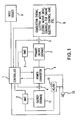
- FIG. 1 is a block diagram schematically illustrating two energy storage devices based in a hybrid vehicle architecture.
- a primary energy storage (e.g., a battery) 7 is coupled to a secondary energy storage 11 through a reconfigurable multi-function power converter 6.
- a controller or ECU 1 communicates with battery management systems (BMS) 2 and BMS 3 and monitors current sensors 4 and 5.
- BMS battery management systems
- the ECU 1 also communicates with elements of the vehicle 8, including a combustion engine, electric motor, electric motor drive, controls for the engine, the vehicle's internal ECU, and the like through a communications bus, such that a controller area network (CAN) is created.
- the ECU 1 is connected to the power converter 6, which manipulates power in accordance with communications from the ECU 1.
- power transfer from the secondary energy storage 11 to the primary energy storage 7 or vehicle 8, as well as power transfer from an electrical grid 12 is controlled by the ECU 1.
- An AC/DC power converter 10 is connected to the charging inlet of the vehicle 8 and provides auxiliary power to the ECU 1 when connected to the electrical grid 12 and indicates the presence of grid power to the ECU 1.
- the secondary energy storage 11 may contain a plurality of battery modules connected in a series arrangement or other arrangement. Each module can be comprised of a parallel, serial or combination thereof battery cell configuration.
- the BMS 2 is connected to the secondary energy storage 11 and monitors various battery parameters, which it then communicates to the ECU 1 and to the vehicle 8 through the ECU 1.
- the ECU 1 also monitors the state of charge of the secondary energy storage or module (Ssoc) 11 based on the parameters it receives from the BMS 2, including information, such as cell voltages, temperatures or current sensor 4 data.
- the reconfigurable power converter 6 may be connected to an external energy source such as the electrical grid 12.
- the ECU 1 controls the converter 6 and may disable the hybrid vehicle or load when it senses that the electrical grid 12 is present.
- energy sources 7 and 11 can be charged or alternatively, can supply AC power to the electrical grid 12 via the reconfigurable power converter 6.
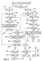
- FIG. 2 is a flow diagram of the controller or ECU 1.
- the ECU 1 determines that the electrical grid 12 is present (operation S20: Yes)
- the system is in a charging mode.
- the power converter 6 is set to a charge enabled status (operation S21), and a disable vehicle drive (DVD) signal is also set to prevent vehicle movement while connected to the electrical grid 12 (operation S22).
- the ECU 1 compares a state of charge of the secondary battery 11 to a target set-point of the secondary battery 11 (SsocTrgt) (operation S23). If the Ssoc is less than SsocTrgt (operation S23: Yes), charging of the secondary battery 11 is enabled (SchEn) (operation S24).
- the value of a charge limit is determined based on a charge limit table which identifies a relationship between the voltages of the electrical grid 12 and the SchrgLmt ( FIG. 3 ).
- the SchrgLmt is further modified based on the high (StmpMax) or low (StmpMin) temperatures as shown in FIG. 4 (operation S25).
- the SchargLmt is further modified based on a battery cell voltage which is determined by a table that identifies the relationship between voltage and current (operation: S25) ( FIG. 5 ).
- the power controller 6 is set to maintain a charge current (Scrnt) at SchrgLmt by setting a secondary state of charge set-point (SPset) (operation S26) or an optimal state of charge according to current conditions.
- SPset secondary state of charge set-point
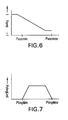
- the state of the charge of the primary energy storage or battery 7 is checked (operation S27). If Psoc is less than the primary state of charge target (PsocTc) (operation S27: Yes), then the primary battery charge set-point is retrieved from the Pchrg table ( FIG. 6 ) (operation S28), which demonstrates a relationship between current and the minimum and maximum state of charge. Also, PsocTc is further modified based on the charge temperature Limit (PchrgLmt) which is determined by a relationship between temperature and minimum or maximum charge ( FIG. 7 ). Then the primary energy storage 7 is enabled (PchEn) (operation S29), and the power converter 6 is set to maintain the charge current to the PchrgLmt by setting PPset.
- PchrgLmt charge temperature Limit
- the power converter 6 stops its charging operation (operation S30), and the flow returns to operation S22.
- operation S27 when Psoc becomes greater than PsocTc (operation S27: No), the Ssoc is again verified, and the charging of the power converter 6 is disabled upon the completion of charging of both energy storage 7 and 11.
- the DVD signal is set to allow vehicle movement (operation S31).
- the ECU 1 waits for a vehicle bus to be pre-charged (BusPrChrg) (operation S32: Yes), and the secondary bus pre-charge is initiated by setting SpreChrg to True (operation S33).
- the ECU 1 waits for the primary battery 7 to connect to the vehicle bus by determining if a primary battery connect (PbattConnect) signal is present (operation S34: Yes). At this point, the secondary battery 11 can also be connected (Sconnect), by setting Sconnect to true (operation S35).
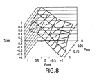
- the ECU 1 retrieves the secondary battery current set-point (Scrnt) from the table shown in FIG. 8 . This value is determined based on vehicle information such as vehicle speed (VS), vehicle load (VL), the temperature of the internal combustion engine (Etmp), and primary current (Pcrnt) (operation S37).
- vehicle information such as vehicle speed (VS), vehicle load (VL), the temperature of the internal combustion engine (Etmp), and primary current (Pcrnt) (operation S37).
- Scrnt is evaluated, and if Scrnt is negative (operation S38: Yes), Ssoc is checked to determine if it is below a secondary state of charge maximum (SsocMax) (operation S39). If Ssoc is less than SsocMax (operation S39: No), SPset is set to Scrnt (operation S40). Otherwise (operation S39: Yes), Spset is set to 0 (operation S41).
- SsocMax secondary state of charge maximum
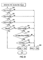
- FIG. 9 is a flow diagram of the ECU 1 to determine whether or not the vehicle 8 is in a vehicle enabled (EVenbl) mode, which allows battery power from the primary battery 7 and/or the secondary battery 11 to be supplied to the vehicle 8.
- EVenbl vehicle enabled
- the ECU 1 determines that Ssoc is greater than SsocMin (operation S90: Yes)
- the value Psoc is checked (operation S91). If Psoc is above a primary state of charge minimum (PsocMin) (operation S91: Yes), the ECU 1 determines if Pcrnt is less than the primary current set point maximum (PcrntMax) (operation S92).
- operation S92 a user selectable by pass (EVbypass) input, which sets the ECU 1 to run only off battery power without warming up the engine and catalyst, is verified (operation S93).
- a non-limiting embodiment may include an user operable push button located within the interior of the vehicle 8, which would allow manipulation of the ECU 1, including toggling the EVbypass function. If the user selects the bypass (operation S93: Yes), EVenabl is set to true (operation S97).
- operation S93 the ECU 1 will check to see if the engine temperature (Etmp) is above its target (EtempTrgt) (operation S94), the catalyst temperature (Ctmp) is between a maximum catalyst temperature (CtempMax) and a target temperature (CtmpTrgt) (operation S95), and if the vehicle set point (VS) is below a maximum vehicle speed set-point (operation S96). If so (operations S94: Yes, S95: Yes, and S96: Yes), the vehicle is placed in the vehicle enabled mode (operation S97). On the other hand, as shown in FIG. 9 , if various conditions are not met (operation S90: No, S91: No, S92: No, S94: No, S95: No, or S96: No), the vehicle is not placed in the vehicle enabled mode (operation S98).
- FIG. 10 is an example of the structure of the power converter 6. It is composed of a generic three phase H bridge electronic circuit and six contactors K1-K6. The device has various modes of operation based on the activation of the contactors K1-K6 and the switching scheme employed by the ECU 1. According to the manipulation of the various switches S1-S6, as a result of various switching algorithms, a DC bus voltage can be transferred between the primary energy storage 7 and the secondary energy storage 11, or alternatively an AC waveform 3 can be generated by the power converter 6.
- FIG. 11 is an example of an illustrative non-limiting embodiment of the power converter 6.
- the contactors K1, K3 and K6 are on, the contactors K2, K4 and K5 are off, and the converter can operate in a battery charging mode, a grid connect mode and a power generation mode.
- switches S1, S2, S3 and S4 of the H bridge are used to rectify the AC waveform 40 and generate a current profile to ensure that a unity power factor is maintained.
- This current waveform is sampled by the controller 1 in order to ensure that the unity power factor is maintained.
- Switch S6 is used to buck the DC bus voltage down to a voltage level for the secondary energy storage 11 and charge the storage 11.
- switches S1,S2,S3 and S4 are used to generate the required current profile.
- Switches S5 and S6 is used as a bi-directional DC-to-DC converter that can either regulate the DC bus voltage to a pre-determined value or control power flow to and from the secondary energy storage 11.
- the power generation mode is similar to the battery charging or grid connect mode.
- the converter 6 receives DC power from the storage 11, and the switches S1, S2, S3 and S4 are used as voltage sources to generate an AC waveform 40.
- Switch S6 is operated as a boost converter to step up the voltage of the secondary energy storage device to the required level for generating the AC waveform.
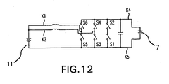
- FIG. 12 is an example of the converter 6 when it operates in a multiphase bi-directional power converter mode, which allows DC-to-DC transfer between energy storage 7 and secondary energy storage 11.
- the contactors K1, K2, K4 and K5 are on, and the contactors K3 and K6 are off.
- the switches S3, S4, S5 and S6 are used to control power flow between the primary energy storage 7 and the secondary energy storage 11.
- the use of only one phase reduces switching loss, which is the main contributor to power loss within the system. This allows the system to achieve maximum power from the energy storage devices.
- another inductor/contactor can be added, such that switch S 1 and S2 can be used as well as shown in FIG 14 .
- FIG. 13 is an example of the power converter operating in the DC-to-AC grid connect mode of the invention.
- AC power can be supplied directly from (or to) the hybrid vehicle's secondary energy storage 11 (SEC) to (or from) the electrical grid 12.
- the secondary energy source 11 is coupled to an external energy source, such as the electrical grid 12 by means of the bi-directional power converter 6.
- diodes are coupled with six switching devices S1-S6 in a parallel relationship.
- the grid or a charge port 12 is connected to an electromagnetic interference (EMI) filter 15, which can optionally be connected to the power converter 6 via inductors 14, which regulate energy or current flow.
- EMI electromagnetic interference
- FIGS. 13(a) - 13(g) show an AC waveform and on/off switching states of the switches S1-S6 when the converter 6 inputs AC power and converts it into DC power for charging the secondary energy source 11.
- the switch S1 opens and closes multiple times ( FIG. 13(b) ).
- the switch S1 may open and close at non-periodic intervals.
- the switch S3 is on, and the switch S6 opens and closes multiple times (but less than the switch S1) ( FIGS. 13(c)-13(g) ).
- the switch S3 opens and closes multiple times ( FIG. 13(d) ).
- the switches S2, S4, and S5 are off, the switch S1 is on, and the switch S6 opens and closes multiple times (but less than the switch S3) (FIGS. 13(b), 13(c), and 13(e)-13(g)).
- a third phase 13 of the conversion when the AC power is in the "positive" portion of the waveform ( Fig. 13(a) ), the switch S4 opens and closes multiple times ( FIG. 13(e) ).
- the switches S1, S3, and S5 are off, the switch S2 is on, and the switch S6 opens and closes multiple times (but less than the switch S3) ( FIGS. 13(b)-13(d), 13(f), and 13(g) ).
- the switch S2 opens and closes multiple times at periodic intervals ( FIG. 13(c) ).
- the switches S1, S3, and S5 are off, the switch S4 is on, and the switch S6 opens and closes multiple times (but less than the switch S3) (FIGS. 13(b) and 13(d)-13(g)) .
- FIGS. 13(h) - 13(n) show an AC waveform and switching states of the switches S1-S6 when the converter 6 converts DC power from the source 11 into output AC power.
- the operation of the converter 6 is similar to the operation described in conjunction with FIGS. 13(a) -13(g) , except that the on/off switching states of the switches S1-S6 are different.
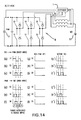
- FIG. 14 is a schematic diagram demonstrating the on/off states of the switches S1 - S6 during two DC-to-DC transfer modes of operation.
- FIGS. 14(a)-(c) and (g)-(i) (or (g')-(i')) show the switching states during the first mode, or boost mode, in which energy is transferred from the secondary energy storage 11 to the primary energy storage 7.
- the switches S1-S6 are implemented via Metal Oxide Semi-Conductor Field Effect Transistors (MOSFETs) and diodes, which are respectively connected in parallel, as shown in the figure. This technique is used to improve efficiency during power conversion.
- MOSFETs Metal Oxide Semi-Conductor Field Effect Transistors
- FIGS. 14 (g)-(i) show the states of the switches S2, S4, and S6 when the system does not use the synchronous rectification technique in the boost mode
- FIGS. 14 (g')-(i') show the states of the switches S2, S4, and S6 when the system uses the technique.
- FIGS. 14(d)-(f) and (j)-(1) show the switching states during the second mode, or buck mode, in which energy is transferred from the primary energy source 7 to the secondary energy source 11.
- FIGS. 14(j)-(1 ) show the states of the switches S1, S3, and S5 when the system does not use the synchronous rectification technique in the buck mode
- FIGS. 14 (j')-(1') show the states of the switches S1, S3, and S5 when the system uses the technique.
- the controller or ECU 1 turns the switch S1 on during a first phase I1, off during a second phase 12, on during a third phase I3, and off during a fourth phase I4 ( FIG. 14(a) ). Also, the switch S3 is turned on between the starting times of the first and second phases I1 and 12, is turned off between the starting times of the second and third phases 12 and 13, and is turned on between the starting times of the third and fourth phases I3 and I4 ( FIG. 14(b) ).
- the switch S5 is turned on and off between the starting times of the various phases I1-I4, except that the on and off times of the switch S5 occur after the corresponding on and off times of the switch S3 ( FIG. 14(c) ).
- the ripple in the output is reduced.
- the switches S2, S4, and S6 are off during the phases I1-I4 (FIGS. 14(g)-(i)) .
- the on and off times of the switches S2, S4, and S6 are staggered during the intervals I1-I4 as shown in FIGS. 14 (g')-(i').
- the controller or ECU 1 turns the switch S2 on during a first phase I1, off during a second phase 12, on during a third phase I3, and off during a fourth phase 14 ( FIG. 14(d) ). Also, the switch S4 is turned on between the starting times of the first and second phases I1 and 12, is turned off between the starting times of the second and third phases 12 and I3, and is turned on between the starting times of the third and fourth phases 13 and 14 ( FIG. 14(e) ).
- the switch S6 is turned on and off between the starting times of the various phases I1-I4; except that the on and off times of the switch S6 occur after the corresponding on and off times of the switch S4 ( FIG. 14(f) ).
- the switches S1, S3, and S5 are off during the phases I1 -I4 ( FIGS. 14(j)-(1 )).
- the on and off times of the switches S1, S3, and S5 are staggered during the intervals I1-I4 as shown in FIGS. 14 (j')-(1').
- FIG. 15 is a schematic diagram demonstrating the on/off states of the switches S1 - S6 during a DC-to-AC transfer modes of operation in which the internal combustion engine (ICE) of the vehicle 8 is used to generated output AC power.
- FIG. 15(a) shows the output AC power
- FIGS. I5(b)-(g) show the switching states of the switches S1-S6 when the AC power is generated from the ICE.
- the controller 1 is coupled to the primary battery 7 and the secondary battery 11 via the power converter 6, and the AC power is supplied to an AC outlet 16, which may be located physically on the secondary energy source 11. Also, the power may be filtered through an EMI filter 15 before being output via the outlet 16, and inductors 14 may be installed to regulate the current flow to the AC outlet 16.
- FIG. 15(a) shows a waveform of the AC power signal after it has passed through the power converter 6 as a result of kinetic energy received from the ICE of the vehicle 8.
- the controller 1 instructs the converter 6 to open and close the switch S2 multiple times ( FIG. 15(c) ).
- the switches S 1 and S4-S6 are off, and the switch S3 is on ( FIGS. 15(b) and 15(d)-15(g) ).
- the switch S 1 opens and closes multiple times ( FIG. 15(b) ). Also, during the second phase I2, the switches S2, S3, S5, and S6 are off, and the switch S4 is on ( FIGS. 15(c)-15(g) ).
- the switch S3 opens and closes multiple times ( FIG. 15(d) ). Furthermore, during the third phase 13, the switches S1 and S4-S6 are off, and the switch S2 is on ( FIGS. 15(b), 15(c), and 15(e)-15(g)).
- the switch S4 opens and closes multiple times ( FIG. 15(e) ). Also, during the fourth phase I4, the switches S2, S3, S5, and S6 are off, and the switch S1 is on ( FIGS. 15(b)-15(d), 15(f), and 15(g)).
- the operation of the power converter 6 can be modified to convert both the energy from the ICE of the vehicle 8 and the power from the secondary energy storage 11 into AC power.
- the operation is the same as the previous operation, except that the controller 1 instructs the converter 6 to turn the switch S5 on and off, as shown in FIG. 13(i) .
Landscapes
- Engineering & Computer Science (AREA)
- Mechanical Engineering (AREA)
- Transportation (AREA)
- Power Engineering (AREA)
- Sustainable Energy (AREA)
- Life Sciences & Earth Sciences (AREA)
- Sustainable Development (AREA)
- Chemical & Material Sciences (AREA)
- Combustion & Propulsion (AREA)
- Automation & Control Theory (AREA)
- Electric Propulsion And Braking For Vehicles (AREA)
- Charge And Discharge Circuits For Batteries Or The Like (AREA)
- Hybrid Electric Vehicles (AREA)
- Secondary Cells (AREA)
Applications Claiming Priority (3)
| Application Number | Priority Date | Filing Date | Title |
|---|---|---|---|
| US88902207P | 2007-02-09 | 2007-02-09 | |
| US88899107P | 2007-02-09 | 2007-02-09 | |
| PCT/US2008/053520 WO2008098230A1 (en) | 2007-02-09 | 2008-02-08 | Control system and hybrid vehicles with reconfigurable multi-function power converter |
Publications (3)
| Publication Number | Publication Date |
|---|---|
| EP2114714A1 EP2114714A1 (en) | 2009-11-11 |
| EP2114714A4 EP2114714A4 (en) | 2010-07-21 |
| EP2114714B1 true EP2114714B1 (en) | 2013-10-23 |
Family
ID=39682137
Family Applications (1)
| Application Number | Title | Priority Date | Filing Date |
|---|---|---|---|
| EP08729474.0A Active EP2114714B1 (en) | 2007-02-09 | 2008-02-08 | Control system and hybrid vehicles with reconfigurable multi-function power converter |
Country Status (7)
| Country | Link |
|---|---|
| US (1) | US8417400B2 (enExample) |
| EP (1) | EP2114714B1 (enExample) |
| JP (3) | JP2010518804A (enExample) |
| KR (1) | KR20100028527A (enExample) |
| CN (1) | CN101674948B (enExample) |
| CA (1) | CA2677847C (enExample) |
| WO (1) | WO2008098230A1 (enExample) |
Cited By (2)
| Publication number | Priority date | Publication date | Assignee | Title |
|---|---|---|---|---|
| WO2016034669A1 (de) | 2014-09-04 | 2016-03-10 | Fraunhofer-Gesellschaft zur Förderung der angewandten Forschung e.V. | Vorrichtung zum laden eines energiespeichers |
| CN106915216A (zh) * | 2017-01-12 | 2017-07-04 | 深圳市国创动力系统有限公司 | 基于一拖多空调系统的混合动力新型电池热管理系统 |
Families Citing this family (47)
| Publication number | Priority date | Publication date | Assignee | Title |
|---|---|---|---|---|
| US7733039B2 (en) * | 2006-10-19 | 2010-06-08 | Ut-Battelle, Llc | Electric vehicle system for charging and supplying electrical power |
| DE102009005265A1 (de) * | 2008-01-25 | 2009-07-30 | Continental Teves Ag & Co. Ohg | Lastansteuerungsschaltung in einem Kraftfahrzeugsteuergerät |
| US8080973B2 (en) | 2008-10-22 | 2011-12-20 | General Electric Company | Apparatus for energy transfer using converter and method of manufacturing same |
| JP5024454B2 (ja) * | 2008-10-31 | 2012-09-12 | トヨタ自動車株式会社 | 電動車両の電源システムおよびその制御方法 |
| EP2353920B1 (en) * | 2008-10-31 | 2019-01-23 | Toyota Jidosha Kabushiki Kaisha | Electrically driven vehicle and electrically driven vehicle control method |
| DE102009024362A1 (de) * | 2009-06-03 | 2010-12-09 | Jungheinrich Ag | Energieversorgungsschaltung für ein Flurförderzeug |
| US9024598B2 (en) * | 2009-06-22 | 2015-05-05 | Toyota Jidosha Kabushiki Kaisha | Converter control device |
| US8106529B2 (en) * | 2009-08-31 | 2012-01-31 | Cnh America Llc | Farm implements with capacitor for peak electric loads |
| EP2481624B1 (en) * | 2009-09-25 | 2018-07-25 | Toyota Jidosha Kabushiki Kaisha | Vehicle charging system and electrically powered vehicle provided with the same |
| KR101116483B1 (ko) * | 2009-12-04 | 2012-02-27 | 삼성에스디아이 주식회사 | 에너지 저장 시스템 |
| WO2011091312A1 (en) | 2010-01-22 | 2011-07-28 | Illinois Tool Works Inc. | Smart grid welding system |
| JP4957827B2 (ja) * | 2010-04-14 | 2012-06-20 | トヨタ自動車株式会社 | 電源システムおよびそれを搭載する車両 |
| US9290097B2 (en) | 2010-11-05 | 2016-03-22 | Robert Louis Steigerwald | Apparatus for transferring energy using onboard power electronics with high-frequency transformer isolation and method of manufacturing same |
| US8742615B2 (en) * | 2011-01-14 | 2014-06-03 | GM Global Technology Operations LLC | Method and apparatus for electric power management in a vehicle |
| WO2012125956A1 (en) * | 2011-03-16 | 2012-09-20 | Johnson Controls Technology Company | Systems and methods for controlling multiple storage devices |
| KR20120116722A (ko) * | 2011-04-13 | 2012-10-23 | 엘지전자 주식회사 | 전기 자동차 및 이의 구동 방법 |
| KR101271251B1 (ko) * | 2011-05-26 | 2013-06-07 | 주식회사 에치케이텍 | 전기 차량용 이동식 급속 충전 장치 |
| EP2722218B1 (en) | 2011-06-17 | 2018-05-16 | Yura Corporation Co., Ltd. | Power relay assembly driving apparatus and driving method thereof |
| KR101508104B1 (ko) * | 2011-07-29 | 2015-04-08 | 미쓰비시덴키 가부시키가이샤 | 전기차의 추진 제어 장치 |
| US8994327B2 (en) * | 2011-08-24 | 2015-03-31 | General Electric Company | Apparatus and method for charging an electric vehicle |
| US9352644B2 (en) * | 2011-08-30 | 2016-05-31 | Toyota Jidosha Kabushiki Kaisha | Vehicle |
| JP5767123B2 (ja) * | 2012-01-06 | 2015-08-19 | 株式会社日本自動車部品総合研究所 | 車両 |
| EP2612786B1 (en) * | 2012-01-09 | 2018-12-12 | Tata Technologies Pte Ltd | Buddy charging for electric vehicles |
| IN2014DN07684A (enExample) * | 2012-03-21 | 2015-05-15 | Toyota Motor Co Ltd | |
| JP5912758B2 (ja) * | 2012-03-29 | 2016-04-27 | 本田技研工業株式会社 | 電動車両の充電制御装置 |
| EP2842221A4 (en) | 2012-04-26 | 2016-05-11 | Gen Electric | CURRENT TRANSFORMER SYSTEM, DAMPING SYSTEM AND METHOD FOR OPERATING A CURRENT TRANSFORMER SYSTEM |
| US8981727B2 (en) | 2012-05-21 | 2015-03-17 | General Electric Company | Method and apparatus for charging multiple energy storage devices |
| US10782721B2 (en) * | 2012-08-27 | 2020-09-22 | Stem, Inc. | Method and apparatus for balancing power on a per phase basis in multi-phase electrical load facilities using an energy storage system |
| US9077052B2 (en) * | 2012-09-06 | 2015-07-07 | General Electric Company | Methods and systems for charging an energy storage device |
| CN102862494B (zh) * | 2012-09-21 | 2014-12-17 | 山推工程机械股份有限公司 | 一种混合动力推土机中回收电能的方法和整车控制器 |
| KR101688485B1 (ko) * | 2013-02-28 | 2016-12-21 | 삼성에스디아이 주식회사 | 에너지 저장 장치 |
| US9428173B2 (en) * | 2013-10-29 | 2016-08-30 | Toyota Motor Engineering & Manufacturing North America, Inc. | Vehicle battery pre-charge feature |
| DE102015101187A1 (de) | 2015-01-28 | 2016-07-28 | Dr. Ing. H.C. F. Porsche Aktiengesellschaft | Hochvolt-Lade-Booster und Verfahren zum Laden einer Gleichstrom-Traktionsbatterie an einer Gleichstrom-Ladesäule sowie entsprechendes Elektrofahrzeug |
| US20160304214A1 (en) * | 2015-04-20 | 2016-10-20 | Hamilton Sundstrand Corporation | Emergency power sources for propulsion systems |
| DE102015108789A1 (de) | 2015-06-03 | 2016-12-08 | Dr. Ing. H.C. F. Porsche Aktiengesellschaft | Energieversorgungssystem für ein Kraftfahrzeug |
| CN106347352B (zh) * | 2015-07-14 | 2019-01-22 | 上汽通用汽车有限公司 | 混合动力能量管理系统及其控制方法 |
| CN106611886B (zh) * | 2015-10-26 | 2020-06-19 | 比亚迪股份有限公司 | 混合动力汽车的放电方法和系统 |
| WO2017197245A1 (en) | 2016-05-13 | 2017-11-16 | Aurora Flight Sciences Corporation | Solar power system and method thereof |
| CN106585421B (zh) * | 2017-01-23 | 2019-04-05 | 福建省汽车工业集团云度新能源汽车股份有限公司 | 一种电动汽车智能充电装置 |
| US10647203B2 (en) | 2018-01-02 | 2020-05-12 | Ge Global Sourcing Llc | Vehicle battery charging system |
| DE102018217309A1 (de) * | 2018-10-10 | 2020-04-16 | Continental Automotive Gmbh | Mehrphasiger Wechselrichter und verwandte Hochspannungstopologie |
| US11642965B2 (en) | 2018-10-11 | 2023-05-09 | Keith Johnson | System and method of powering an external device with a vehicular battery system |
| US11462918B2 (en) | 2019-02-22 | 2022-10-04 | Aurora Flight Sciences Corporation | Battery switch with current control |
| US11133534B2 (en) | 2019-02-22 | 2021-09-28 | Aurora Flight Sciences Corporation | Programmable battery pack |
| US11296540B2 (en) | 2019-02-22 | 2022-04-05 | Aurora Flight Sciences Corporation | Programmable battery pack |
| US11108251B2 (en) | 2019-02-22 | 2021-08-31 | Aurora Flight Sciences Corporation | Battery management system |
| EP4139158A1 (en) * | 2020-04-24 | 2023-03-01 | Ocado Innovation Limited | Energy storage system for a load handling device |
Family Cites Families (37)
| Publication number | Priority date | Publication date | Assignee | Title |
|---|---|---|---|---|
| US4564798A (en) | 1982-10-06 | 1986-01-14 | Escutcheon Associates | Battery performance control |
| US5373195A (en) | 1992-12-23 | 1994-12-13 | General Electric Company | Technique for decoupling the energy storage system voltage from the DC link voltage in AC electric drive systems |
| JPH08107608A (ja) * | 1994-10-04 | 1996-04-23 | Kansai Electric Power Co Inc:The | バッテリ充電装置兼用モータ駆動装置及び電気自動車 |
| JP2880940B2 (ja) * | 1995-12-26 | 1999-04-12 | 埼玉日本電気株式会社 | 携帯電話機 |
| US5710699A (en) | 1996-05-28 | 1998-01-20 | General Electric Company | Power electronic interface circuits for batteries and ultracapacitors in electric vehicles and battery storage systems |
| JP3282655B2 (ja) * | 1997-03-31 | 2002-05-20 | 富士通電装株式会社 | 充電装置 |
| JPH10309002A (ja) * | 1997-04-28 | 1998-11-17 | Fuji Heavy Ind Ltd | ハイブリッド車のエネルギ回生装置 |
| JPH11113185A (ja) * | 1997-09-30 | 1999-04-23 | Tadashi Kaneko | 商用回生共用充電装置 |
| US5926004A (en) * | 1997-10-10 | 1999-07-20 | Schott Power Systems Incorporated | Method and apparatus for charging one or more electric vehicles |
| EP1135840B1 (en) | 1998-07-20 | 2010-05-12 | AlliedSignal Inc. | System and method for monitoring a vehicle battery |
| US6331365B1 (en) | 1998-11-12 | 2001-12-18 | General Electric Company | Traction motor drive system |
| JP2000324857A (ja) | 1999-03-11 | 2000-11-24 | Toyota Motor Corp | 多種電源装置、この電源装置を備えた機器およびモータ駆動装置並びにハイブリッド車両 |
| JP2001163041A (ja) * | 1999-12-07 | 2001-06-19 | Sanyo Electric Co Ltd | 自動車用空調装置 |
| JP3615445B2 (ja) | 2000-01-31 | 2005-02-02 | 三洋電機株式会社 | ハイブリッドカーの電源装置 |
| JP3736300B2 (ja) * | 2000-06-19 | 2006-01-18 | 株式会社日立製作所 | 自動車、およびその電源装置 |
| JP2003009417A (ja) * | 2001-06-20 | 2003-01-10 | Komatsu Forklift Co Ltd | バッテリ充電装置及びそのバッテリ充電装置を装着したバッテリフォークリフト |
| JP2003088130A (ja) * | 2001-09-07 | 2003-03-20 | Matsushita Electric Ind Co Ltd | バッテリ内蔵型電力変換装置 |
| JP2003102181A (ja) * | 2001-09-25 | 2003-04-04 | Toyota Motor Corp | 電力供給システムおよび電力供給方法 |
| JP2003187418A (ja) * | 2001-12-13 | 2003-07-04 | Fuji Electric Co Ltd | 磁気記録媒体およびその製造方法、並びに該磁気記録媒体を使用する磁気記録装置 |
| JP4023171B2 (ja) * | 2002-02-05 | 2007-12-19 | トヨタ自動車株式会社 | 負荷駆動装置、負荷駆動装置における電力貯蔵装置の充電制御方法および充電制御をコンピュータに実行させるためのプログラムを記録したコンピュータ読取可能な記録媒体 |
| JP3872758B2 (ja) * | 2003-01-08 | 2007-01-24 | 株式会社日立製作所 | 電源制御装置 |
| JP3983681B2 (ja) * | 2003-01-14 | 2007-09-26 | 株式会社マキタ | 充電装置 |
| JP2004336888A (ja) * | 2003-05-07 | 2004-11-25 | Toshiba Corp | 電力補償装置及び方法 |
| US6946818B2 (en) * | 2003-10-14 | 2005-09-20 | General Motors Corporation | Method of determining battery power limits for an energy storage system of a hybrid electric vehicle |
| US7352154B2 (en) * | 2004-01-14 | 2008-04-01 | Vanner, Inc. | Electrical system control for a vehicle |
| US7057376B2 (en) * | 2004-01-14 | 2006-06-06 | Vanner, Inc. | Power management system for vehicles |
| JP2005295711A (ja) * | 2004-03-31 | 2005-10-20 | Takeo Saito | ハイブリッド電気自動車 |
| US20050285564A1 (en) * | 2004-06-25 | 2005-12-29 | Ford Global Technologies, Llc | Automatic charging of a high voltage battery in a hybrid electric vehicle |
| JP4566658B2 (ja) * | 2004-08-24 | 2010-10-20 | パナソニックエコシステムズ株式会社 | 電源装置 |
| JP2006129619A (ja) * | 2004-10-29 | 2006-05-18 | Hitachi Koki Co Ltd | 電池の充電装置 |
| JP2006158123A (ja) * | 2004-11-30 | 2006-06-15 | Toyota Motor Corp | 交流電圧出力装置およびそれを備えた車両 |
| WO2006121761A2 (en) * | 2005-05-05 | 2006-11-16 | Afs Trinity Power Corporation | Plug-in hybrid vehicle with fast energy storage |
| JP4839722B2 (ja) * | 2005-08-08 | 2011-12-21 | トヨタ自動車株式会社 | 車両の電源装置 |
| US20070111044A1 (en) * | 2005-08-17 | 2007-05-17 | Chang Seok G | Hybrid cell and method of driving the same |
| JP4412260B2 (ja) * | 2005-09-01 | 2010-02-10 | トヨタ自動車株式会社 | ハイブリッド自動車 |
| CA2623398A1 (en) * | 2005-09-23 | 2007-04-05 | Afs Trinity Power Corporation | Method and apparatus for power electronics and control of plug-in hybrid propulsion with fast energy storage |
| JP4491434B2 (ja) * | 2006-05-29 | 2010-06-30 | トヨタ自動車株式会社 | 電力制御装置およびそれを備えた車両 |
-
2008
- 2008-02-08 EP EP08729474.0A patent/EP2114714B1/en active Active
- 2008-02-08 CA CA2677847A patent/CA2677847C/en not_active Expired - Fee Related
- 2008-02-08 CN CN2008800092398A patent/CN101674948B/zh active Active
- 2008-02-08 WO PCT/US2008/053520 patent/WO2008098230A1/en not_active Ceased
- 2008-02-08 US US12/028,772 patent/US8417400B2/en not_active Expired - Fee Related
- 2008-02-08 KR KR1020097018759A patent/KR20100028527A/ko not_active Ceased
- 2008-02-08 JP JP2009549284A patent/JP2010518804A/ja active Pending
-
2013
- 2013-02-21 JP JP2013032314A patent/JP2013144543A/ja active Pending
- 2013-06-25 JP JP2013132937A patent/JP2013216318A/ja active Pending
Cited By (4)
| Publication number | Priority date | Publication date | Assignee | Title |
|---|---|---|---|---|
| WO2016034669A1 (de) | 2014-09-04 | 2016-03-10 | Fraunhofer-Gesellschaft zur Förderung der angewandten Forschung e.V. | Vorrichtung zum laden eines energiespeichers |
| DE102014217703A1 (de) * | 2014-09-04 | 2016-03-10 | Fraunhofer-Gesellschaft zur Förderung der angewandten Forschung e.V. | Vorrichtung zum laden eines energiespeichers |
| US10367363B2 (en) | 2014-09-04 | 2019-07-30 | Fraunhofer-Gesellschaft Zur Foerderung Der Angewandten Forschung E.V. | Device for charging an energy store |
| CN106915216A (zh) * | 2017-01-12 | 2017-07-04 | 深圳市国创动力系统有限公司 | 基于一拖多空调系统的混合动力新型电池热管理系统 |
Also Published As
| Publication number | Publication date |
|---|---|
| US8417400B2 (en) | 2013-04-09 |
| CN101674948A (zh) | 2010-03-17 |
| JP2013144543A (ja) | 2013-07-25 |
| CA2677847C (en) | 2015-08-11 |
| EP2114714A1 (en) | 2009-11-11 |
| US20080215200A1 (en) | 2008-09-04 |
| EP2114714A4 (en) | 2010-07-21 |
| JP2013216318A (ja) | 2013-10-24 |
| JP2010518804A (ja) | 2010-05-27 |
| WO2008098230A1 (en) | 2008-08-14 |
| CN101674948B (zh) | 2013-09-04 |
| CA2677847A1 (en) | 2008-08-14 |
| KR20100028527A (ko) | 2010-03-12 |
Similar Documents
| Publication | Publication Date | Title |
|---|---|---|
| EP2114714B1 (en) | Control system and hybrid vehicles with reconfigurable multi-function power converter | |
| Rivera et al. | Electric vehicle charging infrastructure: From grid to battery | |
| CN106476635B (zh) | 具有多个能量存储装置的混合系统 | |
| JP5563577B2 (ja) | 双方向インバータ・チャージャ及びインバータ・チャージャ装置 | |
| US9172252B2 (en) | Power supply apparatus for electrically powered vehicle and method for controlling the same | |
| JP5348326B2 (ja) | 電動車両およびその充電制御方法 | |
| CN103187772B (zh) | 电动汽车及电动汽车向外供电的系统 | |
| US20110100735A1 (en) | Propulsion Energy Storage Control System and Method of Control | |
| JP5497381B2 (ja) | 車両 | |
| US11152791B2 (en) | Solar energy based mobile electric vehicle fast charger system | |
| CN108475937A (zh) | 一种用于包含一个或多个感应线圈的感应负载的控制器 | |
| KR101330349B1 (ko) | 전력 변환 장치 및 이를 이용한 전력 변환 방법 | |
| CN102957188A (zh) | 用于对电动车辆充电的设备和方法 | |
| WO2013097821A1 (zh) | 电动汽车及电动汽车向外供电的系统 | |
| CN101803147A (zh) | 蓄电装置的充电控制装置以及充电控制方法 | |
| JP2014143817A (ja) | 車両の電源システム | |
| JP2013150369A (ja) | 系統連系用電力変換システム | |
| CN101483388A (zh) | Dc/dc转换器装置及驱动方法、车辆、燃料电池系统 | |
| WO2014026460A1 (zh) | 一种集成开关磁阻电机驱动与低压电池充电的变换装置 | |
| JP2008312382A (ja) | 電源システムおよびそれを備えた車両、ならびに電源システムの制御方法およびその制御方法をコンピュータに実行させるためのプログラムを記録したコンピュータ読取可能な記録媒体 | |
| Woo et al. | Comparison of integrated battery chargers for plug-in hybrid electric vehicles: Topology and control | |
| US12107454B1 (en) | Efficient charging of an external energy storage system from a vehicle battery system | |
| Pawase et al. | Controllable bidirectional power transfer between electric vehicle and grid at different loading condition with solar power | |
| Surada et al. | A novel approach towards integration of propulsion machine inverter with energy storage charger in plug-in hybrid electric vehicles | |
| Shi et al. | Modified dual inverter drive enabling on-board fast charging of electric vehicles |
Legal Events
| Date | Code | Title | Description |
|---|---|---|---|
| PUAI | Public reference made under article 153(3) epc to a published international application that has entered the european phase |
Free format text: ORIGINAL CODE: 0009012 |
|
| 17P | Request for examination filed |
Effective date: 20090828 |
|
| AK | Designated contracting states |
Kind code of ref document: A1 Designated state(s): AT BE BG CH CY CZ DE DK EE ES FI FR GB GR HR HU IE IS IT LI LT LU LV MC MT NL NO PL PT RO SE SI SK TR |
|
| DAX | Request for extension of the european patent (deleted) | ||
| A4 | Supplementary search report drawn up and despatched |
Effective date: 20100617 |
|
| REG | Reference to a national code |
Ref country code: DE Ref legal event code: R079 Ref document number: 602008028284 Country of ref document: DE Free format text: PREVIOUS MAIN CLASS: B60K0001000000 Ipc: B60W0010260000 |
|
| RIC1 | Information provided on ipc code assigned before grant |
Ipc: B60L 11/18 20060101ALI20121109BHEP Ipc: B60W 10/26 20060101AFI20121109BHEP Ipc: B60L 11/14 20060101ALI20121109BHEP |
|
| GRAP | Despatch of communication of intention to grant a patent |
Free format text: ORIGINAL CODE: EPIDOSNIGR1 |
|
| INTG | Intention to grant announced |
Effective date: 20130506 |
|
| GRAS | Grant fee paid |
Free format text: ORIGINAL CODE: EPIDOSNIGR3 |
|
| GRAA | (expected) grant |
Free format text: ORIGINAL CODE: 0009210 |
|
| AK | Designated contracting states |
Kind code of ref document: B1 Designated state(s): AT BE BG CH CY CZ DE DK EE ES FI FR GB GR HR HU IE IS IT LI LT LU LV MC MT NL NO PL PT RO SE SI SK TR |
|
| REG | Reference to a national code |
Ref country code: GB Ref legal event code: FG4D |
|
| REG | Reference to a national code |
Ref country code: CH Ref legal event code: EP |
|
| REG | Reference to a national code |
Ref country code: AT Ref legal event code: REF Ref document number: 637393 Country of ref document: AT Kind code of ref document: T Effective date: 20131115 |
|
| REG | Reference to a national code |
Ref country code: IE Ref legal event code: FG4D |
|
| REG | Reference to a national code |
Ref country code: DE Ref legal event code: R096 Ref document number: 602008028284 Country of ref document: DE Effective date: 20131219 |
|
| REG | Reference to a national code |
Ref country code: NL Ref legal event code: VDEP Effective date: 20131023 |
|
| REG | Reference to a national code |
Ref country code: AT Ref legal event code: MK05 Ref document number: 637393 Country of ref document: AT Kind code of ref document: T Effective date: 20131023 |
|
| REG | Reference to a national code |
Ref country code: LT Ref legal event code: MG4D |
|
| PG25 | Lapsed in a contracting state [announced via postgrant information from national office to epo] |
Ref country code: IS Free format text: LAPSE BECAUSE OF FAILURE TO SUBMIT A TRANSLATION OF THE DESCRIPTION OR TO PAY THE FEE WITHIN THE PRESCRIBED TIME-LIMIT Effective date: 20140223 Ref country code: SE Free format text: LAPSE BECAUSE OF FAILURE TO SUBMIT A TRANSLATION OF THE DESCRIPTION OR TO PAY THE FEE WITHIN THE PRESCRIBED TIME-LIMIT Effective date: 20131023 Ref country code: LT Free format text: LAPSE BECAUSE OF FAILURE TO SUBMIT A TRANSLATION OF THE DESCRIPTION OR TO PAY THE FEE WITHIN THE PRESCRIBED TIME-LIMIT Effective date: 20131023 Ref country code: NO Free format text: LAPSE BECAUSE OF FAILURE TO SUBMIT A TRANSLATION OF THE DESCRIPTION OR TO PAY THE FEE WITHIN THE PRESCRIBED TIME-LIMIT Effective date: 20140123 Ref country code: FI Free format text: LAPSE BECAUSE OF FAILURE TO SUBMIT A TRANSLATION OF THE DESCRIPTION OR TO PAY THE FEE WITHIN THE PRESCRIBED TIME-LIMIT Effective date: 20131023 Ref country code: HR Free format text: LAPSE BECAUSE OF FAILURE TO SUBMIT A TRANSLATION OF THE DESCRIPTION OR TO PAY THE FEE WITHIN THE PRESCRIBED TIME-LIMIT Effective date: 20131023 Ref country code: NL Free format text: LAPSE BECAUSE OF FAILURE TO SUBMIT A TRANSLATION OF THE DESCRIPTION OR TO PAY THE FEE WITHIN THE PRESCRIBED TIME-LIMIT Effective date: 20131023 Ref country code: BE Free format text: LAPSE BECAUSE OF FAILURE TO SUBMIT A TRANSLATION OF THE DESCRIPTION OR TO PAY THE FEE WITHIN THE PRESCRIBED TIME-LIMIT Effective date: 20131023 |
|
| PG25 | Lapsed in a contracting state [announced via postgrant information from national office to epo] |
Ref country code: CY Free format text: LAPSE BECAUSE OF FAILURE TO SUBMIT A TRANSLATION OF THE DESCRIPTION OR TO PAY THE FEE WITHIN THE PRESCRIBED TIME-LIMIT Effective date: 20131023 Ref country code: LV Free format text: LAPSE BECAUSE OF FAILURE TO SUBMIT A TRANSLATION OF THE DESCRIPTION OR TO PAY THE FEE WITHIN THE PRESCRIBED TIME-LIMIT Effective date: 20131023 Ref country code: ES Free format text: LAPSE BECAUSE OF FAILURE TO SUBMIT A TRANSLATION OF THE DESCRIPTION OR TO PAY THE FEE WITHIN THE PRESCRIBED TIME-LIMIT Effective date: 20131023 Ref country code: AT Free format text: LAPSE BECAUSE OF FAILURE TO SUBMIT A TRANSLATION OF THE DESCRIPTION OR TO PAY THE FEE WITHIN THE PRESCRIBED TIME-LIMIT Effective date: 20131023 |
|
| PG25 | Lapsed in a contracting state [announced via postgrant information from national office to epo] |
Ref country code: PT Free format text: LAPSE BECAUSE OF FAILURE TO SUBMIT A TRANSLATION OF THE DESCRIPTION OR TO PAY THE FEE WITHIN THE PRESCRIBED TIME-LIMIT Effective date: 20140224 |
|
| REG | Reference to a national code |
Ref country code: DE Ref legal event code: R097 Ref document number: 602008028284 Country of ref document: DE |
|
| PG25 | Lapsed in a contracting state [announced via postgrant information from national office to epo] |
Ref country code: EE Free format text: LAPSE BECAUSE OF FAILURE TO SUBMIT A TRANSLATION OF THE DESCRIPTION OR TO PAY THE FEE WITHIN THE PRESCRIBED TIME-LIMIT Effective date: 20131023 |
|
| PG25 | Lapsed in a contracting state [announced via postgrant information from national office to epo] |
Ref country code: IT Free format text: LAPSE BECAUSE OF FAILURE TO SUBMIT A TRANSLATION OF THE DESCRIPTION OR TO PAY THE FEE WITHIN THE PRESCRIBED TIME-LIMIT Effective date: 20131023 Ref country code: CZ Free format text: LAPSE BECAUSE OF FAILURE TO SUBMIT A TRANSLATION OF THE DESCRIPTION OR TO PAY THE FEE WITHIN THE PRESCRIBED TIME-LIMIT Effective date: 20131023 Ref country code: SK Free format text: LAPSE BECAUSE OF FAILURE TO SUBMIT A TRANSLATION OF THE DESCRIPTION OR TO PAY THE FEE WITHIN THE PRESCRIBED TIME-LIMIT Effective date: 20131023 Ref country code: PL Free format text: LAPSE BECAUSE OF FAILURE TO SUBMIT A TRANSLATION OF THE DESCRIPTION OR TO PAY THE FEE WITHIN THE PRESCRIBED TIME-LIMIT Effective date: 20131023 Ref country code: RO Free format text: LAPSE BECAUSE OF FAILURE TO SUBMIT A TRANSLATION OF THE DESCRIPTION OR TO PAY THE FEE WITHIN THE PRESCRIBED TIME-LIMIT Effective date: 20131023 |
|
| PLBE | No opposition filed within time limit |
Free format text: ORIGINAL CODE: 0009261 |
|
| STAA | Information on the status of an ep patent application or granted ep patent |
Free format text: STATUS: NO OPPOSITION FILED WITHIN TIME LIMIT |
|
| PG25 | Lapsed in a contracting state [announced via postgrant information from national office to epo] |
Ref country code: MC Free format text: LAPSE BECAUSE OF FAILURE TO SUBMIT A TRANSLATION OF THE DESCRIPTION OR TO PAY THE FEE WITHIN THE PRESCRIBED TIME-LIMIT Effective date: 20131023 Ref country code: LU Free format text: LAPSE BECAUSE OF FAILURE TO SUBMIT A TRANSLATION OF THE DESCRIPTION OR TO PAY THE FEE WITHIN THE PRESCRIBED TIME-LIMIT Effective date: 20140208 Ref country code: DK Free format text: LAPSE BECAUSE OF FAILURE TO SUBMIT A TRANSLATION OF THE DESCRIPTION OR TO PAY THE FEE WITHIN THE PRESCRIBED TIME-LIMIT Effective date: 20131023 |
|
| REG | Reference to a national code |
Ref country code: CH Ref legal event code: PL |
|
| 26N | No opposition filed |
Effective date: 20140724 |
|
| GBPC | Gb: european patent ceased through non-payment of renewal fee |
Effective date: 20140208 |
|
| PG25 | Lapsed in a contracting state [announced via postgrant information from national office to epo] |
Ref country code: CH Free format text: LAPSE BECAUSE OF NON-PAYMENT OF DUE FEES Effective date: 20140228 Ref country code: LI Free format text: LAPSE BECAUSE OF NON-PAYMENT OF DUE FEES Effective date: 20140228 |
|
| REG | Reference to a national code |
Ref country code: DE Ref legal event code: R097 Ref document number: 602008028284 Country of ref document: DE Effective date: 20140724 |
|
| REG | Reference to a national code |
Ref country code: FR Ref legal event code: ST Effective date: 20141031 |
|
| REG | Reference to a national code |
Ref country code: IE Ref legal event code: MM4A |
|
| PG25 | Lapsed in a contracting state [announced via postgrant information from national office to epo] |
Ref country code: IE Free format text: LAPSE BECAUSE OF NON-PAYMENT OF DUE FEES Effective date: 20140208 Ref country code: FR Free format text: LAPSE BECAUSE OF NON-PAYMENT OF DUE FEES Effective date: 20140228 Ref country code: GB Free format text: LAPSE BECAUSE OF NON-PAYMENT OF DUE FEES Effective date: 20140208 |
|
| PG25 | Lapsed in a contracting state [announced via postgrant information from national office to epo] |
Ref country code: SI Free format text: LAPSE BECAUSE OF FAILURE TO SUBMIT A TRANSLATION OF THE DESCRIPTION OR TO PAY THE FEE WITHIN THE PRESCRIBED TIME-LIMIT Effective date: 20131023 |
|
| REG | Reference to a national code |
Ref country code: DE Ref legal event code: R082 Ref document number: 602008028284 Country of ref document: DE Representative=s name: DTS PATENT- UND RECHTSANWAELTE SCHNEKENBUEHL U, DE |
|
| REG | Reference to a national code |
Ref country code: DE Ref legal event code: R082 Ref document number: 602008028284 Country of ref document: DE Representative=s name: DTS PATENT- UND RECHTSANWAELTE SCHNEKENBUEHL U, DE Ref country code: DE Ref legal event code: R081 Ref document number: 602008028284 Country of ref document: DE Owner name: A123 SYSTEMS LLC (N.D.GES.D. STAATES DELAWARE), US Free format text: FORMER OWNER: A123 SYSTEMS,INC., WATERTOWN, MASS., US |
|
| PG25 | Lapsed in a contracting state [announced via postgrant information from national office to epo] |
Ref country code: MT Free format text: LAPSE BECAUSE OF FAILURE TO SUBMIT A TRANSLATION OF THE DESCRIPTION OR TO PAY THE FEE WITHIN THE PRESCRIBED TIME-LIMIT Effective date: 20131023 |
|
| PG25 | Lapsed in a contracting state [announced via postgrant information from national office to epo] |
Ref country code: BG Free format text: LAPSE BECAUSE OF FAILURE TO SUBMIT A TRANSLATION OF THE DESCRIPTION OR TO PAY THE FEE WITHIN THE PRESCRIBED TIME-LIMIT Effective date: 20131023 |
|
| PG25 | Lapsed in a contracting state [announced via postgrant information from national office to epo] |
Ref country code: GR Free format text: LAPSE BECAUSE OF FAILURE TO SUBMIT A TRANSLATION OF THE DESCRIPTION OR TO PAY THE FEE WITHIN THE PRESCRIBED TIME-LIMIT Effective date: 20140124 |
|
| PG25 | Lapsed in a contracting state [announced via postgrant information from national office to epo] |
Ref country code: HU Free format text: LAPSE BECAUSE OF FAILURE TO SUBMIT A TRANSLATION OF THE DESCRIPTION OR TO PAY THE FEE WITHIN THE PRESCRIBED TIME-LIMIT; INVALID AB INITIO Effective date: 20080208 Ref country code: TR Free format text: LAPSE BECAUSE OF FAILURE TO SUBMIT A TRANSLATION OF THE DESCRIPTION OR TO PAY THE FEE WITHIN THE PRESCRIBED TIME-LIMIT Effective date: 20131023 |
|
| P01 | Opt-out of the competence of the unified patent court (upc) registered |
Effective date: 20230507 |
|
| PGFP | Annual fee paid to national office [announced via postgrant information from national office to epo] |
Ref country code: DE Payment date: 20250227 Year of fee payment: 18 |