EP2113711A1 - Hotspot-Grenz-D-Optik - Google Patents
Hotspot-Grenz-D-Optik Download PDFInfo
- Publication number
- EP2113711A1 EP2113711A1 EP09006068A EP09006068A EP2113711A1 EP 2113711 A1 EP2113711 A1 EP 2113711A1 EP 09006068 A EP09006068 A EP 09006068A EP 09006068 A EP09006068 A EP 09006068A EP 2113711 A1 EP2113711 A1 EP 2113711A1
- Authority
- EP
- European Patent Office
- Prior art keywords
- optic
- beam pattern
- desired beam
- body portion
- creating
- Prior art date
- Legal status (The legal status is an assumption and is not a legal conclusion. Google has not performed a legal analysis and makes no representation as to the accuracy of the status listed.)
- Granted
Links
- 230000003287 optical effect Effects 0.000 claims description 8
- 238000002156 mixing Methods 0.000 claims description 4
- 238000007493 shaping process Methods 0.000 claims description 2
- 238000005452 bending Methods 0.000 description 3
- 230000000694 effects Effects 0.000 description 3
- 230000004313 glare Effects 0.000 description 3
- 238000010276 construction Methods 0.000 description 2
- 238000004519 manufacturing process Methods 0.000 description 2
- 239000012141 concentrate Substances 0.000 description 1
- 230000003247 decreasing effect Effects 0.000 description 1
- 230000035945 sensitivity Effects 0.000 description 1
- 238000004904 shortening Methods 0.000 description 1
- 230000005428 wave function Effects 0.000 description 1
Images


Classifications
-
- G—PHYSICS
- G02—OPTICS
- G02B—OPTICAL ELEMENTS, SYSTEMS OR APPARATUS
- G02B19/00—Condensers, e.g. light collectors or similar non-imaging optics
- G02B19/0033—Condensers, e.g. light collectors or similar non-imaging optics characterised by the use
- G02B19/0047—Condensers, e.g. light collectors or similar non-imaging optics characterised by the use for use with a light source
- G02B19/0061—Condensers, e.g. light collectors or similar non-imaging optics characterised by the use for use with a light source the light source comprising a LED
-
- F—MECHANICAL ENGINEERING; LIGHTING; HEATING; WEAPONS; BLASTING
- F21—LIGHTING
- F21K—NON-ELECTRIC LIGHT SOURCES USING LUMINESCENCE; LIGHT SOURCES USING ELECTROCHEMILUMINESCENCE; LIGHT SOURCES USING CHARGES OF COMBUSTIBLE MATERIAL; LIGHT SOURCES USING SEMICONDUCTOR DEVICES AS LIGHT-GENERATING ELEMENTS; LIGHT SOURCES NOT OTHERWISE PROVIDED FOR
- F21K9/00—Light sources using semiconductor devices as light-generating elements, e.g. using light-emitting diodes [LED] or lasers
- F21K9/60—Optical arrangements integrated in the light source, e.g. for improving the colour rendering index or the light extraction
- F21K9/69—Details of refractors forming part of the light source
-
- F—MECHANICAL ENGINEERING; LIGHTING; HEATING; WEAPONS; BLASTING
- F21—LIGHTING
- F21S—NON-PORTABLE LIGHTING DEVICES; SYSTEMS THEREOF; VEHICLE LIGHTING DEVICES SPECIALLY ADAPTED FOR VEHICLE EXTERIORS
- F21S41/00—Illuminating devices specially adapted for vehicle exteriors, e.g. headlamps
- F21S41/20—Illuminating devices specially adapted for vehicle exteriors, e.g. headlamps characterised by refractors, transparent cover plates, light guides or filters
- F21S41/25—Projection lenses
- F21S41/27—Thick lenses
-
- F—MECHANICAL ENGINEERING; LIGHTING; HEATING; WEAPONS; BLASTING
- F21—LIGHTING
- F21V—FUNCTIONAL FEATURES OR DETAILS OF LIGHTING DEVICES OR SYSTEMS THEREOF; STRUCTURAL COMBINATIONS OF LIGHTING DEVICES WITH OTHER ARTICLES, NOT OTHERWISE PROVIDED FOR
- F21V17/00—Fastening of component parts of lighting devices, e.g. shades, globes, refractors, reflectors, filters, screens, grids or protective cages
- F21V17/10—Fastening of component parts of lighting devices, e.g. shades, globes, refractors, reflectors, filters, screens, grids or protective cages characterised by specific fastening means or way of fastening
-
- G—PHYSICS
- G02—OPTICS
- G02B—OPTICAL ELEMENTS, SYSTEMS OR APPARATUS
- G02B19/00—Condensers, e.g. light collectors or similar non-imaging optics
- G02B19/0004—Condensers, e.g. light collectors or similar non-imaging optics characterised by the optical means employed
- G02B19/0009—Condensers, e.g. light collectors or similar non-imaging optics characterised by the optical means employed having refractive surfaces only
- G02B19/0014—Condensers, e.g. light collectors or similar non-imaging optics characterised by the optical means employed having refractive surfaces only at least one surface having optical power
-
- G—PHYSICS
- G02—OPTICS
- G02B—OPTICAL ELEMENTS, SYSTEMS OR APPARATUS
- G02B27/00—Optical systems or apparatus not provided for by any of the groups G02B1/00 - G02B26/00, G02B30/00
- G02B27/09—Beam shaping, e.g. changing the cross-sectional area, not otherwise provided for
- G02B27/0938—Using specific optical elements
- G02B27/095—Refractive optical elements
- G02B27/0955—Lenses
-
- F—MECHANICAL ENGINEERING; LIGHTING; HEATING; WEAPONS; BLASTING
- F21—LIGHTING
- F21S—NON-PORTABLE LIGHTING DEVICES; SYSTEMS THEREOF; VEHICLE LIGHTING DEVICES SPECIALLY ADAPTED FOR VEHICLE EXTERIORS
- F21S41/00—Illuminating devices specially adapted for vehicle exteriors, e.g. headlamps
- F21S41/10—Illuminating devices specially adapted for vehicle exteriors, e.g. headlamps characterised by the light source
- F21S41/14—Illuminating devices specially adapted for vehicle exteriors, e.g. headlamps characterised by the light source characterised by the type of light source
- F21S41/141—Light emitting diodes [LED]
-
- F—MECHANICAL ENGINEERING; LIGHTING; HEATING; WEAPONS; BLASTING
- F21—LIGHTING
- F21V—FUNCTIONAL FEATURES OR DETAILS OF LIGHTING DEVICES OR SYSTEMS THEREOF; STRUCTURAL COMBINATIONS OF LIGHTING DEVICES WITH OTHER ARTICLES, NOT OTHERWISE PROVIDED FOR
- F21V17/00—Fastening of component parts of lighting devices, e.g. shades, globes, refractors, reflectors, filters, screens, grids or protective cages
- F21V17/10—Fastening of component parts of lighting devices, e.g. shades, globes, refractors, reflectors, filters, screens, grids or protective cages characterised by specific fastening means or way of fastening
- F21V17/12—Fastening of component parts of lighting devices, e.g. shades, globes, refractors, reflectors, filters, screens, grids or protective cages characterised by specific fastening means or way of fastening by screwing
-
- F—MECHANICAL ENGINEERING; LIGHTING; HEATING; WEAPONS; BLASTING
- F21—LIGHTING
- F21Y—INDEXING SCHEME ASSOCIATED WITH SUBCLASSES F21K, F21L, F21S and F21V, RELATING TO THE FORM OR THE KIND OF THE LIGHT SOURCES OR OF THE COLOUR OF THE LIGHT EMITTED
- F21Y2115/00—Light-generating elements of semiconductor light sources
- F21Y2115/10—Light-emitting diodes [LED]
Definitions
- the present invention relates to an optic used for producing various beam patterns, such as spread beam patterns, hot spot beam patterns, bending beam patterns, and combinations thereof.
- LED headlamp designs use a projector system to build the high beam hotspot and imaged masks or source shapes to generate the sharp cutoff in the low beam pattern.
- This is a costly, complex and inefficient solution.
- the pattern produced was very wide and smooth, providing insufficient intensity in the center of the pattern; therefore, a projector system was still needed to produce the high beam and low beam hotspots required to achieve a complete beam pattern.
- the light from the light source often does not provide light for the entire input surface area. This will often result in a "banding effect," where waves of alternating light and dark area will be seen in the resulting beam pattern.
- the present invention solves the intensity and cutoff problems of typical optics by using an optic with a tall, thin profile having specific characteristics that allow the production of higher maximum intensities required for a high beam pattern.
- the optic of the present invention also provides sufficiently sharp horizontal gradients needed for a low beam pattern, which is required for good photometric and on road performance.
- the present invention also seeks to develop tall, thin optics that can efficiently deliver high intensity light, and can also be used to form the required shapes in the headlamp beam pattern.
- the present invention is an optic used for producing a desired beam pattern with a body portion having a height and a thickness, and at least one sidewall profile, as well as an input port for receiving light from a light source.
- the optic of the present invention also includes an output surface formed as part of the body portion on the opposite side of the body portion in relation to the input port, at least one leg portion formed as part of the body portion, and at least one alignment feature formed as part of the at least one leg portion, the at least one alignment feature for controlling the alignment of the optic in relation to the light source.
- a first embodiment of the present invention includes a curved output surface, and specially shaped top, bottom, and side walls.
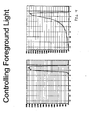
- a series of sloped, planar walls near the input port coupled with the thin crossection combine to create a smooth, wide horizontal light pattern having a sharp, controllable gradient in the vertical direction, and a smooth exponential pattern fade out below horizontal to the deep forground.
- This optic is used to create fog lamp beams, or the wide spread portion of headlamp beam patterns. If needed, the smoothness of the pattern can be improved by applying a horizontal wave function to the output surface.
- a slight variation of this optic which is designed to produce an inverted cutoff pattern is combined with the first optic to provide a high beam spread pattern.
- a second embodiment of the present invention is an optic which is thicker and taller, having different and specially shaped top, bottom, and side walls. These changes allow a single LED to produce a much higher (aproximatly 10 times higher) maximum intensity compared to the optic described in the first embodiment.
- the optic of this embodiment provides the high intensity portion of a high beam headlamp pattern.
- a third embodiment of the present invnetion is an optic that has features similar to those of the first and second optics combined, but without the small, planar surfaces near the input port. These features create a high intensity pattern, having a horizontal cutoff with a high vertical gradient and smooth foreground blending.
- This optic can be used to provide a portion of the lowbeam hotspot or caravanal lighting that improves illuminationion around curves.
- a fourth embodiment of the present invention is an optic which combines the features of the third embodiment with additional features that allow it to produce a high intensity pattern that fills only one quadrent (when the beam is projected onto a graph) by producing relativly sharp gradients in both the horizontal and vertical directions, and is combined with the third optic to create an improved low beam hotspot pattern.
- a fith embodiment of the present invention is an optic which combines features of the third embodiment with different features to produce a beam pattern that is similar to that produced by the combination of the third and fourth embodiments, having both a horizontal spread with vertical cutoff and a stepped pattern with a horizontal cutoff.
- a sixth embodiment of the present invention is an optic that combines features of the fifth optic with additional features, making it possible to create a complete low beam pattern with a single optic. In all cases, multiple devices will be required until the optical output of a single LED is sufficient to produce a low beam pattern of sufficient intensity.
- Figure 1 is a first perspective view of an optic, according to a first embodiment of the present invention
- Figure 2 is a second perspective view of an optic, according to a first embodiment of the present invention.
- Figure 3A is a sectional side view taken along lines 3A-3A of Figure 2 ;
- Figure 3B is a top sectional view taken along lines 3B-3B of Figure 2 ;
- Figure 3C is a sectional front view taken along lines 3C-3C of Figure 2 ;
- Figure 4 is a graph depicting a vertical cross-section of the beam pattern produced by an optic according to a first embodiment of the present invention
- Figure 5 is a beam pattern produced by an optic, according to a first embodiment of the present invention.
- Figure 6A is a first perspective view of an optic, according to a second embodiment of the present invention.
- Figure 6B is a second perspective view of an optic, according to a second embodiment of the present invention.
- Figure 7A is a sectional side view taken along lines 7A-7A of Figure 6B ;
- Figure 7B is a sectional top view taken along lines 7B-7B of Figure 6B ;
- Figure 8 is a projected beam pattern produced by an optic, according to a second embodiment of the present invention.
- Figure 9A is a first perspective view of an optic, according to a third embodiment of the present invention.
- Figure 9B is a second perspective view of an optic, according to a third embodiment of the present invention.
- Figure 10A is a sectional side view taken along lines 10A-10A of Figure 9B ;
- Figure 10B is a sectional top view taken along lines 10B-10B of Figure 9B ;
- Figure 10C is a sectional top view taken along lines 10C-10C of Figure 9B ;
- Figure 11 is a projected beam pattern produced by an optic, according to a third embodiment of the present invention.
- Figure 12 is a low beam pattern divided up into sections used to produce an optic, according to a first embodiment of the present invention
- Figure 13A is a first perspective view of an optic, according to a fourth embodiment of the present invention.
- Figure 13B is a second perspective view of an optic, according to a fourth embodiment of the present invention.
- Figure 14A is a sectional side view taken along lines 14A-14A of Figure 13B ;
- Figure 14B is a sectional top view taken along lines 14B-14B of Figure 13B ;
- Figure 14C is a sectional front view taken along lines 14C-14C of Figure 13B ;
- Figure 15 is a projected beam pattern produced by an optic, according to a fourth embodiment of the present invention.
- Figure 16A is a first perspective view of an optic, according to a fifth embodiment of the present invention.
- Figure 16B is a second perspective view of an optic, according to a fifth embodiment of the present invention.
- Figure 17A is a sectional side view taken along lines 17A-17A of Figure 16B ;
- Figure 17B is a sectional top view taken along lines 17B-17B of Figure 16B ;
- Figure 17C is a sectional front view taken along lines 17C-17C of Figure 16B ;
- Figure 18 is a beam pattern produced by an optic, according to a fifth embodiment of the present invention.
- Figure 19 is a beam pattern produced by the combination of a fourth and fifth embodiment of an optic, according to the present invention.
- Figure 20A is a first perspective view of an optic, according to a sixth embodiment of the present invention.
- Figure 20B is a second perspective view of an optic, according to a sixth embodiment of the present invention.
- Figure 21A is a sectional side view taken along lines 21A-21A of Figure 20B ;
- Figure 21B is a first sectional top view of an optic taken along lines 21 B-21 B of Figure 20B ;
- Figure 21C is a second sectional top view taken along lines 21C-21C of Figure 20B ;
- Figure 21D is a third sectional top view taken along lines 21D-21D of Figure 20B ;
- Figure 21E is a sectional front view taken along lines 21E-21E of Figure 20B ;
- Figure 22 is a beam pattern produced by an optic, according to a sixth embodiment of the present invention.
- Figure 23A is a first perspective view of an optic, according to a seventh embodiment of the present invention.
- Figure 23B is a second perspective view of an optic, according to a seventh embodiment of the present invention.
- Figure 24A is a sectional side view taken along lines 24A-24A of Figure 23B ;
- Figure 24B is a first sectional top view taken along lines 248-24B of Figure 23B ;
- Figure 24C is a second sectional top view taken along lines 24C-24C of Figure 23B ;
- Figure 24D is a first sectional front view taken along lines 24D-24D of Figure 23B ;
- Figure 24E is a second sectional front view taken along lines 24E-24E of Figure 23B ;
- Figure 25 is a low beam pattern produced by a seventh embodiment of an optic, according to the present invention.
- Figure 26 is a beam pattern produced by a seventh embodiment of an optic, according to the present invention.
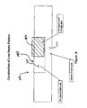
- FIG. 1 A first embodiment of an optic according to the present invention is shown in Figures 1, 2 , and 3A-3C generally at 10.
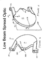
- the optic 10 is configured to be a low beam spread optic.
- the optic 10 has several new features that improve on and eliminate the problems with the prior art.
- Light is received into the optic 10 from a light emitting diode, or LED (not shown) directly coupled to the body 12 of the optic 10 through an input port 301, shortening the light path and improving optical efficiency.
- the optic 10 also includes a wall 302 and an output surface 304 having a shape so as to focus the light near a notch 303, forming a smooth, blended foreground pattern as shown in Figure 5 , and by the vertical cross-section of the pattern, which is shown in Figure 4 .
- the patterns shown in Figure 4 are achieved with greatly reduced sensitivity of the pattern to LED alignment in relation to the optic 10.
- the horizontal distribution of the output light of the optic 10 is also alternatively controlled by placement of a bend, or "kink” 305 in the side wall, shown generally at 312, between tapered section 314 and essentially straight section 316.
- a bend, or "kink” 305 is located near the input port 301, this results in a wider, more distributed, output pattern.
- a pattern is produced which concentrates more light in the middle of the pattern.
- the flatness of the top portion of the beam pattern is controlled by changing the profile 307 of the sidewall 312; a thinner section in the center of the profile 307 of the sidewall 312 serves to flatten the outboard ends of the pattern as shown in Figure 5 .
- the graph as shown in Figure 5 includes a horizontal cut off line 320, and a vertical cut off line 322.
- the optic 10 also includes a bottom half 310, and a top half 311.
- the sidewalls 312 are substantially perpendicular to the output surface 304.
- the optic 10 also has two leg portions 318 which are attached to two LED alignment features 308,309.
- the leg portions 318 also include a curved profile section 324, one of which extends into a first lower wall portion 326 and a second lower wall portion 328.
- the curved profile section 324 helps to improve the strength of the optic 10.
- Each leg portion 318 also optionally includes an aperture 334, where a fastener (not shown) such as a screw will extend through the aperture 334 to secure the optic 10 to a desired surface. It is also within the scope of the invention that the leg portions 318 may also be clamped down to a desired surface, or the optic 10 may be attached to the desired surface through the use of snap features.
- the optic 10 also includes a height 330 and a thickness 332 which are adjusted to achieve the desired beam pattern.
- the height 330 is 40mm
- the thickness 332 is 3.4mm.
- Asymmetric shaping of the sidewall profile 307 can be used to achieve the sloped pattern for ECE beam patterns.
- the configuration of the optic 10 as shown in Figures 1-3C allows for the addition of the precise LED alignment features 308,309.
- the LED alignment feature 308 controls height above the LED and, the LED alignment feature 309 controls alignment over the LED.
- Improved horizontal smoothness is achieved by adding a multi-cycle wave 306, which for example can be in the form of a sinusoidal wave or tangential arcs having various numbers of cycles, to the profile of the output surface 304.
- a "cycle" is defined as one complete alternating variation in the pattern of the wave. For example, if a sinusoidal wave were used, one cycle would be the completion of 2 ⁇ radians.
- the multi-cycle wave 306 will reduce the "banding effect" (alternating bright and dark areas of light) which can occur when using various types of optics.
- the wave 306 as shown in Figure 3C is a two-cycle wave, and extends only along the top half 311 of the optic 10. Extending the wave 306 from the top to the bottom of the optic 10 reintroduces undesirable light above the horizontal line 320 of the desired beam pattern shown in Figure 5 . By eliminating or reducing the waves from the bottom half, generally shown at 310, of the optic 10, any undesirable light above the horizontal line 320 is eliminated.
- the multi-cycle wave 306 in this embodiment is also a two-cycle wave, meaning that two complete cycles were used to create the wave 306.
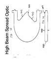
- Figures 6A-7B show the configuration for another embodiment of the present invention in the form of a high beam spread optic 910.
- This embodiment of the optic 910 includes similar features to the optic 10 previously described, but is configured for having a high beam spread pattern, as shown in Figure 8 .
- This embodiment includes a notch 901, which is inverted compared to the notch 303 of the low beam spread optic 10 shown in Figures 1 and 2 . This inversion creates a pattern having a cutoff on the bottom of the pattern.
- This embodiment also includes a first lower wall portion 902 and a second lower wall portion 903, as with the previous embodiment; however, part of the second lower wall portion 903 includes and angled portion 1001, which has been made shallower that the second lower wall portion 328 as compared to the optic 10 in Figures 1 and 2 . Introducing the angled portion 1001 into the second lower wall portion 903 redirects light that would have been ineffective below the area indicated generally at 1101 in Figure 8 , into the useful pattern as shown in Figure 8 . Similar features are optionally employed in the optic 910 that are shown are part of the low beam optic 10 shown in Figures 1 and 2 . A narrower pattern is produced by increasing the thickness 1002 of the optic 910. Improved smoothness is achieved in the optic 910 with a three-cycle output wave 1003, as opposed to a two-cycle output wave. Additionally, because the thickness 1002 of the optic 910 has changed, the position of the kink 1004 has changed as well.
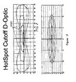
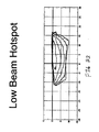
- Figure 9A through 10C show an optic generally at 1410 used form producing a high beam hot spot optic 1410 to achieve higher maximum intensity for use in headlamp high beam applications. Achieving theses higher levels of performance requires increasing the size of the optic 1410.
- the optic height 1401 is increased to 66mm (from an optic height 330 of 40mm described in the optic 10), and the thickness 1402 is increased to 10mm (from a thickness 332 of 3.4mm described in the optic 10).
- the optic 1410 also includes an input port 1403, similar to the previous embodiments. However the width 1406 of the input port 1403 is decreased to 1.2mm. The width 1406 of the input port 1403 and the thickness 1402 of the output surface 1407 have a significant influence on the pattern of the beam produced.
- the curved side profile 1404 of the optic 1410 as shown in Figure 14C is adjusted to produce the highest intensity across the center of the optic 1410.
- the optic 1410 also has first and second lower wall portions 1408,1409 which have a hyperbolic profile 1405, which improves the maximum intensity.
- the resulting output pattern is shown in Figure 11 . Maximum intensity produced by this optic 1410 is approximately ten times that produced by the spread optics 10,910.
- the low beam pattern, shown generally at 1400 in Figure 12 , produced by the spread optics 10 is broken up into several parts.
- the pattern 1400 includes a spread portion 1412, a hot spot portion 1414, and a hot spot cutoff portion 1416.
- Other embodiments of the invention discussed below act to reduce or modify the hot spot cutoff portion 1416.
- the embodiments discussed below also act to reduce or eliminate light produced in the test point area 1418 such, which is required to be below a maximum value to be used for passenger vehicles.
- Figures 13A through 14C show another embodiment of the present invention in the form of a bending/low beam optic, shown generally at 1700, which uses a similar approach used with regard to the high beam hot spot optic 1410 to achieve the higher intensity necessary for the hot spot used with a low beam.
- the optic height 1704 of the optic 1700 is larger, once again increased to 66mm, and the thickness 1705 is again increased to be 10mm thick.
- a notch 1701 and wall 1702 features are used in a similar manner to what was used on the spread optics 10,910.
- the optic 1700 also includes a first lower wall portion 1706 and a second lower wall portion 1707.
- the first lower wall portion 1706 is hyperbolic in shape, similar to that in the high beam hotspot optic 1410.
- the second lower wall portion 1707 is substantially flat, and has no effect on optical performance.
- the resulting optical pattern is shown in Figure 15 .
- the pattern shown in Figure 18 is also ideal for being used in bending light generation by angling the optic 1700 off-axis to the left and right.
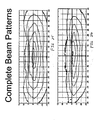
- Figures 16A through 17C show another embodiment of the present invention in the form of the construction of an optic, shown generally at 2000, that also creates a beam pattern as shown in Figure 18 .
- the resulting pattern is that of a complete low beam hot spot, shown in Figure 19 .
- the light in the test point area 1418 has been reduced or eliminated.
- Combining the optic 1700 and the optic 2000 in Figures 13A-14C and 16A-17C incorporates three new features to achieve the desired output.
- Previously disclosed features of the optic 1700 are employed to create the vertical cutoff, i.e. the notch 2005 and wall 2006.
- the horizontal cutoff is achieved by applying a second notch 2001 and wall 2002 feature ninety degrees to the first at a different scale in the horizontal direction.
- a focusing shape 2003 is also applied to the output surface 2004.
- Figure 20A through 21E show the construction of another embodiment of the invention in the form of an optic, shown generally at 2300, that achieves a similar output to that of the combined output of the previous two optics 1700,2000.
- This performance is achieved by sectioning the optic 2300 along various points of the output surface 2301 into multiple zones. Three zones are used in this embodiment, identified as a first zone 2301, a second 2302, and a third zone 2303, are taken along the sectioned areas of Figure 20B . Each of these three zones 2301,2302,2303 have an independent sidewall 2401, 2403, 2405 and output shapes 2402, 2404, 2406, respectively, as shown in Figures 24B-24E .
- the resultant output of the optic 2300 is shown in Figure 22 . This optic 2300 produces higher optical efficiency.
- Figures 23A through 24E show an optic that can achieve a complete low beam pattern in a single part.
- the features of this optic 2500 provide both spread and hotspot functions. This is achieved by combining the smaller spread optic 10,910 with the larger hotspot optic 1410,1700. The size split must occur below approximately four degrees from horizontal 2502.
- the optic 2500 includes a smaller spread section 2503 and a larger hotspot section 2501, the larger hotspot section 2501 has a top portion 2502. There is a horizontal axis 2504 which divides the two sections 2501,2503. The top portion 2502 of the larger hotspot section 2501 descends at an angle 2505 below the horizontal axis 2504.
- the larger hotspot section 2501 may be broken into multiple sections similar to the optic 2300 previously described, each having an independent sidewall profile, output surface, and size configurations.
- Figures 25 shows a high beam pattern from the optic 2500
- Figure 26 shows a low beam pattern from the optic 2500.
Landscapes
- Physics & Mathematics (AREA)
- Engineering & Computer Science (AREA)
- Optics & Photonics (AREA)
- General Engineering & Computer Science (AREA)
- General Physics & Mathematics (AREA)
- Microelectronics & Electronic Packaging (AREA)
- Non-Portable Lighting Devices Or Systems Thereof (AREA)
Applications Claiming Priority (1)
| Application Number | Priority Date | Filing Date | Title |
|---|---|---|---|
| US12611608P | 2008-05-01 | 2008-05-01 |
Publications (2)
| Publication Number | Publication Date |
|---|---|
| EP2113711A1 true EP2113711A1 (de) | 2009-11-04 |
| EP2113711B1 EP2113711B1 (de) | 2015-12-16 |
Family
ID=40763456
Family Applications (1)
| Application Number | Title | Priority Date | Filing Date |
|---|---|---|---|
| EP09006068.2A Active EP2113711B1 (de) | 2008-05-01 | 2009-05-04 | Hotspot-Grenz-D-Optik |
Country Status (3)
| Country | Link |
|---|---|
| US (1) | US8475019B2 (de) |
| EP (1) | EP2113711B1 (de) |
| CA (1) | CA2664963A1 (de) |
Cited By (3)
| Publication number | Priority date | Publication date | Assignee | Title |
|---|---|---|---|---|
| US8475019B2 (en) | 2008-05-01 | 2013-07-02 | Magna International Inc. | Hotspot cutoff D-optic |
| US8517584B2 (en) | 2008-05-01 | 2013-08-27 | Magna International Inc. | Hotspot cutoff d-optic |
| EP3062013A1 (de) * | 2015-02-26 | 2016-08-31 | T.Y.C. Brother Industrial Co., Ltd. | Fahrzeuglampe |
Families Citing this family (6)
| Publication number | Priority date | Publication date | Assignee | Title |
|---|---|---|---|---|
| DE102011082844A1 (de) | 2011-09-16 | 2013-03-21 | Zumtobel Lighting Gmbh | Beleuchtungsanordnung insbesondere zur Rettungswegbeleuchtung |
| US9052095B2 (en) * | 2012-10-01 | 2015-06-09 | Valeo North America, Inc. | Light guide fixture system |
| KR20150018288A (ko) * | 2013-08-09 | 2015-02-23 | 현대모비스 주식회사 | 차량용 램프 및 이를 포함하는 차량 |
| DE102013110345A1 (de) | 2013-09-19 | 2015-04-02 | Hella Kgaa Hueck & Co. | Beleuchtungsvorrichtung für Fahrzeuge |
| AT518098B1 (de) * | 2015-12-17 | 2017-11-15 | Zkw Group Gmbh | Zusatzscheinwerfer für Fahrzeuge sowie Scheinwerfersystem |
| CN205991447U (zh) * | 2016-05-05 | 2017-03-01 | 芜湖法雷奥汽车照明系统有限公司 | 光导组件以及车灯 |
Citations (11)
| Publication number | Priority date | Publication date | Assignee | Title |
|---|---|---|---|---|
| EP0769653A1 (de) * | 1995-10-18 | 1997-04-23 | Denso Corporation | Lichtverteilungsvorrichtung für Fahrzeug-Scheinwerfer |
| EP1357332A2 (de) * | 2002-04-23 | 2003-10-29 | Koito Manufacturing Co., Ltd | Lichtquelleneinheit für Fahrzeugleuchte |
| US20040156209A1 (en) | 2003-02-10 | 2004-08-12 | Hiroyuki Ishida | Vehicular headlamp and optical unit |
| DE10314256A1 (de) * | 2003-03-29 | 2004-10-07 | Hella Kg Hueck & Co. | Leuchte für Fahrzeuge |
| AT8253U1 (de) * | 2005-03-14 | 2006-04-15 | Zizala Lichtsysteme Gmbh | Linse für einen fahrzeugscheinwerfer |
| US20060087860A1 (en) * | 2004-10-27 | 2006-04-27 | Koito Manufacturing Co., Ltd. | Vehicle illumination lamp |
| WO2006097067A1 (de) | 2005-03-16 | 2006-09-21 | Osram Opto Semiconductors Gmbh | Licht emittierendes modul mit led und passstiften für die montage eines optischen elements |
| WO2007027474A2 (en) * | 2005-08-31 | 2007-03-08 | Osram Sylvania Inc. | Led headlamp system |
| DE102006020961A1 (de) * | 2006-05-05 | 2007-11-08 | Hella Kgaa Hueck & Co. | Scheinwerfer für Fahrzeuge |
| EP1873011A2 (de) * | 2006-06-29 | 2008-01-02 | Magna International Inc. | Rekonfigurierbarer Scheinwerfer und Steuersystem zur Rekonfigurierung eines Fahrzeugbeleuchtungssystems |
| EP2039990A1 (de) * | 2007-09-20 | 2009-03-25 | Siteco Beleuchtungstechnik GmbH | Trägerelement mit Leuchtdiodeneinheiten |
Family Cites Families (47)
| Publication number | Priority date | Publication date | Assignee | Title |
|---|---|---|---|---|
| US3911430A (en) * | 1974-04-17 | 1975-10-07 | Fairchild Camera Instr Co | Alpha-numeric display package |
| US5005108A (en) * | 1989-02-10 | 1991-04-02 | Lumitex, Inc. | Thin panel illuminator |
| JP3341325B2 (ja) * | 1992-06-19 | 2002-11-05 | 株式会社デンソー | 車両用灯具装置 |
| JP3521441B2 (ja) * | 1993-06-16 | 2004-04-19 | 株式会社デンソー | 車両用灯具装置 |
| US5349504A (en) * | 1993-07-12 | 1994-09-20 | Dialight Corporation | Multi-level lightpipe design for SMD LEDs |
| JPH07312103A (ja) | 1994-03-22 | 1995-11-28 | Nippondenso Co Ltd | 灯具装置 |
| JPH07326204A (ja) * | 1994-05-31 | 1995-12-12 | Nippondenso Co Ltd | 車両用灯具装置 |
| JPH08195103A (ja) * | 1994-11-15 | 1996-07-30 | Nippondenso Co Ltd | 車両用灯具装置 |
| JPH08167301A (ja) * | 1994-12-12 | 1996-06-25 | Nippondenso Co Ltd | 車両用前照灯 |
| JPH08203303A (ja) * | 1995-01-31 | 1996-08-09 | Nippondenso Co Ltd | 灯具装置 |
| JPH08339704A (ja) * | 1995-06-12 | 1996-12-24 | Nippondenso Co Ltd | 車両用灯具装置 |
| US6048083A (en) * | 1995-06-30 | 2000-04-11 | Mcdermott; Kevin | Bent focal line lighting device |
| US5555161A (en) * | 1995-09-11 | 1996-09-10 | Delco Electronics Corporation | Bi-functional light pipe and display assembly |
| US6340824B1 (en) * | 1997-09-01 | 2002-01-22 | Kabushiki Kaisha Toshiba | Semiconductor light emitting device including a fluorescent material |
| US6502952B1 (en) * | 1999-06-23 | 2003-01-07 | Fred Jack Hartley | Light emitting diode assembly for flashlights |
| FR2797678B1 (fr) | 1999-08-19 | 2001-12-07 | Peugeot Citroen Automobiles Sa | Dispositif d'eclairage et/ou de signalisation pour vehicule et vehicule comportant un tel dispositif |
| JP3977004B2 (ja) * | 2000-10-13 | 2007-09-19 | 株式会社小糸製作所 | 室内照明灯 |
| DE10060491A1 (de) | 2000-12-06 | 2002-06-13 | Hella Kg Hueck & Co | Fahrzeugscheinwerfer |
| DE10062103A1 (de) | 2000-12-13 | 2002-07-18 | Hella Kg Hueck & Co | Fahrzeugscheinwerfer |
| DE10065624C2 (de) * | 2000-12-29 | 2002-11-14 | Hans Kragl | Kopplungsanordnung zum optischen Koppeln eines Lichtwellenleiters mit einem elektro-optischen oder opto-elektrischen Halbleiterwandler |
| US6929384B2 (en) * | 2001-02-09 | 2005-08-16 | Nichia Corporation | Led indicator lamp |
| US6637921B2 (en) * | 2001-09-28 | 2003-10-28 | Osram Sylvania Inc. | Replaceable LED bulb with interchangeable lens optic |
| EP2397875A3 (de) * | 2001-12-14 | 2012-05-02 | QUALCOMM MEMS Technologies, Inc. | Einförmiges Beleuchtungssystem |
| US6976770B2 (en) * | 2002-10-14 | 2005-12-20 | Guide Corporation | Hermetically sealed lamp housing and method of making |
| CN100383573C (zh) * | 2002-12-02 | 2008-04-23 | 3M创新有限公司 | 多光源照明系统 |
| US7025476B2 (en) * | 2003-04-25 | 2006-04-11 | Acuity Brands, Inc. | Prismatic reflectors with a plurality of curved surfaces |
| DE10325330B4 (de) | 2003-06-04 | 2010-06-02 | Automotive Lighting Reutlingen Gmbh | Scheinwerfer für Kraftfahrzeuge |
| JP4024721B2 (ja) * | 2003-06-20 | 2007-12-19 | 株式会社小糸製作所 | 車両用灯具及び光源モジュール |
| US20040263346A1 (en) | 2003-06-27 | 2004-12-30 | Guide Corporation, A Delaware Corporation | Solid state adaptive forward lighting system |
| US7218892B2 (en) * | 2003-06-27 | 2007-05-15 | The Boeing Company | Passive repeater/terminator |
| JP2005044698A (ja) * | 2003-07-24 | 2005-02-17 | Koito Mfg Co Ltd | 車両用灯具及び光源モジュール |
| WO2005050262A2 (en) * | 2003-11-14 | 2005-06-02 | Light Prescriptions Innovators, Llc | Dichroic beam combiner utilizing blue led with green phosphor |
| JP2005158362A (ja) * | 2003-11-21 | 2005-06-16 | Stanley Electric Co Ltd | 車両用灯具 |
| US20050116635A1 (en) * | 2003-12-02 | 2005-06-02 | Walson James E. | Multiple LED source and method for assembling same |
| JP4264335B2 (ja) * | 2003-12-05 | 2009-05-13 | 株式会社小糸製作所 | 車両用前照灯 |
| US7270447B2 (en) * | 2005-05-23 | 2007-09-18 | Ge Security | Uniform luminance and color mixing lens for LED device |
| JP4535965B2 (ja) * | 2005-08-16 | 2010-09-01 | 株式会社小糸製作所 | 車両用灯具 |
| US7588359B2 (en) * | 2005-09-26 | 2009-09-15 | Osram Sylvania Inc. | LED lamp with direct optical coupling in axial arrangement |
| US7329033B2 (en) * | 2005-10-25 | 2008-02-12 | Visteon Global Technologies, Inc. | Convectively cooled headlamp assembly |
| US7560742B2 (en) * | 2005-11-28 | 2009-07-14 | Magna International Inc. | Semiconductor-based lighting systems and lighting system components for automotive use |
| US20070127258A1 (en) * | 2005-12-07 | 2007-06-07 | Bwt Property, Inc. | Projection lighting apparatus for marking and demarcation |
| US7341365B2 (en) * | 2005-12-16 | 2008-03-11 | Ford Global Technologies, Llc | LED unit for a vehicle lamp assembly |
| GB2443835A (en) | 2006-11-15 | 2008-05-21 | Aspoeck Systems Gmbh | Integral vehicle rear lamp |
| CA2673690A1 (en) * | 2007-01-25 | 2008-07-31 | Magna International Inc. | Semiconductor light source element for beam forming |
| US7686486B2 (en) * | 2007-06-30 | 2010-03-30 | Osram Sylvania Inc. | LED lamp module |
| CA2716941A1 (en) * | 2008-03-26 | 2009-10-01 | Magna International Inc. | Fog lamp and the like employing semiconductor light sources |
| CA2664963A1 (en) | 2008-05-01 | 2009-11-01 | Magna International Inc. | Hotspot cutoff d-optic |
-
2009
- 2009-04-30 CA CA002664963A patent/CA2664963A1/en not_active Abandoned
- 2009-04-30 US US12/433,186 patent/US8475019B2/en active Active
- 2009-05-04 EP EP09006068.2A patent/EP2113711B1/de active Active
Patent Citations (11)
| Publication number | Priority date | Publication date | Assignee | Title |
|---|---|---|---|---|
| EP0769653A1 (de) * | 1995-10-18 | 1997-04-23 | Denso Corporation | Lichtverteilungsvorrichtung für Fahrzeug-Scheinwerfer |
| EP1357332A2 (de) * | 2002-04-23 | 2003-10-29 | Koito Manufacturing Co., Ltd | Lichtquelleneinheit für Fahrzeugleuchte |
| US20040156209A1 (en) | 2003-02-10 | 2004-08-12 | Hiroyuki Ishida | Vehicular headlamp and optical unit |
| DE10314256A1 (de) * | 2003-03-29 | 2004-10-07 | Hella Kg Hueck & Co. | Leuchte für Fahrzeuge |
| US20060087860A1 (en) * | 2004-10-27 | 2006-04-27 | Koito Manufacturing Co., Ltd. | Vehicle illumination lamp |
| AT8253U1 (de) * | 2005-03-14 | 2006-04-15 | Zizala Lichtsysteme Gmbh | Linse für einen fahrzeugscheinwerfer |
| WO2006097067A1 (de) | 2005-03-16 | 2006-09-21 | Osram Opto Semiconductors Gmbh | Licht emittierendes modul mit led und passstiften für die montage eines optischen elements |
| WO2007027474A2 (en) * | 2005-08-31 | 2007-03-08 | Osram Sylvania Inc. | Led headlamp system |
| DE102006020961A1 (de) * | 2006-05-05 | 2007-11-08 | Hella Kgaa Hueck & Co. | Scheinwerfer für Fahrzeuge |
| EP1873011A2 (de) * | 2006-06-29 | 2008-01-02 | Magna International Inc. | Rekonfigurierbarer Scheinwerfer und Steuersystem zur Rekonfigurierung eines Fahrzeugbeleuchtungssystems |
| EP2039990A1 (de) * | 2007-09-20 | 2009-03-25 | Siteco Beleuchtungstechnik GmbH | Trägerelement mit Leuchtdiodeneinheiten |
Cited By (3)
| Publication number | Priority date | Publication date | Assignee | Title |
|---|---|---|---|---|
| US8475019B2 (en) | 2008-05-01 | 2013-07-02 | Magna International Inc. | Hotspot cutoff D-optic |
| US8517584B2 (en) | 2008-05-01 | 2013-08-27 | Magna International Inc. | Hotspot cutoff d-optic |
| EP3062013A1 (de) * | 2015-02-26 | 2016-08-31 | T.Y.C. Brother Industrial Co., Ltd. | Fahrzeuglampe |
Also Published As
| Publication number | Publication date |
|---|---|
| US8475019B2 (en) | 2013-07-02 |
| US20090273935A1 (en) | 2009-11-05 |
| EP2113711B1 (de) | 2015-12-16 |
| CA2664963A1 (en) | 2009-11-01 |
Similar Documents
| Publication | Publication Date | Title |
|---|---|---|
| EP2113711A1 (de) | Hotspot-Grenz-D-Optik | |
| KR102145335B1 (ko) | 컷오프 라인을 갖는 광 다발을 생성하기 위한 자동차 헤드라이트용 조명 유닛 | |
| JP7376583B2 (ja) | すれ違いビーム前照灯 | |
| JP7274626B2 (ja) | ライトガイドを備えた自動車両用の照明装置 | |
| US9134000B2 (en) | Illuminating module for a motor vehicle | |
| US20150131305A1 (en) | Primary optical element, lighting module and headlamp for a motor vehicle | |
| JP6548887B2 (ja) | 車両用灯具 | |
| US9097401B2 (en) | Light module for motor-vehicle headlight | |
| CN105659025A (zh) | 具有带正方形散射函数的微结构的光学结构 | |
| JP2007265994A (ja) | 単一又は複数のフェーセット付きレンズを用いたledプロジェクタヘッドライト | |
| EP2500628A2 (de) | KFZ-Scheinwerfer | |
| EP2767750A2 (de) | Fahrzeugscheinwerfer | |
| CN103672664A (zh) | 车用照明装置 | |
| EP3467373B1 (de) | Fahrzeugscheinwerfer und fahrzeug damit | |
| TW201702520A (zh) | 具有狹長輻射圖案之透鏡 | |
| US20200158305A1 (en) | Light guide-based high-low beam system and vehicle lamp | |
| US9879837B2 (en) | Optical structure for signal light | |
| JPH08167301A (ja) | 車両用前照灯 | |
| US8517584B2 (en) | Hotspot cutoff d-optic | |
| JP2019096486A (ja) | 車両用灯具 | |
| JP2020013779A (ja) | 車両用灯具及び投影レンズ | |
| CN107667248B (zh) | 管状发光设备 | |
| CN220728005U (zh) | 用于车辆的灯具和包括灯具的车辆 | |
| US11125409B2 (en) | Image tilt correction system of automotive beam pattern | |
| JP6046381B2 (ja) | 車両用灯具 |
Legal Events
| Date | Code | Title | Description |
|---|---|---|---|
| PUAI | Public reference made under article 153(3) epc to a published international application that has entered the european phase |
Free format text: ORIGINAL CODE: 0009012 |
|
| AK | Designated contracting states |
Kind code of ref document: A1 Designated state(s): AT BE BG CH CY CZ DE DK EE ES FI FR GB GR HR HU IE IS IT LI LT LU LV MC MK MT NL NO PL PT RO SE SI SK TR |
|
| 17P | Request for examination filed |
Effective date: 20100208 |
|
| 17Q | First examination report despatched |
Effective date: 20100330 |
|
| REG | Reference to a national code |
Ref country code: DE Ref legal event code: R079 Ref document number: 602009035189 Country of ref document: DE Free format text: PREVIOUS MAIN CLASS: F21K0007000000 Ipc: F21K0099000000 |
|
| GRAP | Despatch of communication of intention to grant a patent |
Free format text: ORIGINAL CODE: EPIDOSNIGR1 |
|
| RIC1 | Information provided on ipc code assigned before grant |
Ipc: F21W 101/10 20060101ALN20150522BHEP Ipc: G02B 19/00 20060101ALI20150522BHEP Ipc: F21S 8/10 20060101ALI20150522BHEP Ipc: F21Y 101/02 20060101ALN20150522BHEP Ipc: F21K 99/00 20100101AFI20150522BHEP |
|
| INTG | Intention to grant announced |
Effective date: 20150618 |
|
| RIC1 | Information provided on ipc code assigned before grant |
Ipc: F21K 99/00 20100101AFI20150605BHEP Ipc: G02B 19/00 20060101ALI20150605BHEP Ipc: F21S 8/10 20060101ALI20150605BHEP Ipc: F21Y 101/02 20060101ALN20150605BHEP Ipc: F21W 101/10 20060101ALN20150605BHEP |
|
| GRAS | Grant fee paid |
Free format text: ORIGINAL CODE: EPIDOSNIGR3 |
|
| GRAA | (expected) grant |
Free format text: ORIGINAL CODE: 0009210 |
|
| AK | Designated contracting states |
Kind code of ref document: B1 Designated state(s): AT BE BG CH CY CZ DE DK EE ES FI FR GB GR HR HU IE IS IT LI LT LU LV MC MK MT NL NO PL PT RO SE SI SK TR |
|
| REG | Reference to a national code |
Ref country code: GB Ref legal event code: FG4D |
|
| REG | Reference to a national code |
Ref country code: CH Ref legal event code: EP |
|
| REG | Reference to a national code |
Ref country code: IE Ref legal event code: FG4D |
|
| REG | Reference to a national code |
Ref country code: AT Ref legal event code: REF Ref document number: 765731 Country of ref document: AT Kind code of ref document: T Effective date: 20160115 |
|
| REG | Reference to a national code |
Ref country code: DE Ref legal event code: R096 Ref document number: 602009035189 Country of ref document: DE |
|
| REG | Reference to a national code |
Ref country code: FR Ref legal event code: PLFP Year of fee payment: 8 |
|
| REG | Reference to a national code |
Ref country code: NL Ref legal event code: MP Effective date: 20151216 |
|
| REG | Reference to a national code |
Ref country code: LT Ref legal event code: MG4D |
|
| PG25 | Lapsed in a contracting state [announced via postgrant information from national office to epo] |
Ref country code: HR Free format text: LAPSE BECAUSE OF FAILURE TO SUBMIT A TRANSLATION OF THE DESCRIPTION OR TO PAY THE FEE WITHIN THE PRESCRIBED TIME-LIMIT Effective date: 20151216 Ref country code: NO Free format text: LAPSE BECAUSE OF FAILURE TO SUBMIT A TRANSLATION OF THE DESCRIPTION OR TO PAY THE FEE WITHIN THE PRESCRIBED TIME-LIMIT Effective date: 20160316 Ref country code: LT Free format text: LAPSE BECAUSE OF FAILURE TO SUBMIT A TRANSLATION OF THE DESCRIPTION OR TO PAY THE FEE WITHIN THE PRESCRIBED TIME-LIMIT Effective date: 20151216 |
|
| REG | Reference to a national code |
Ref country code: AT Ref legal event code: MK05 Ref document number: 765731 Country of ref document: AT Kind code of ref document: T Effective date: 20151216 |
|
| PG25 | Lapsed in a contracting state [announced via postgrant information from national office to epo] |
Ref country code: GR Free format text: LAPSE BECAUSE OF FAILURE TO SUBMIT A TRANSLATION OF THE DESCRIPTION OR TO PAY THE FEE WITHIN THE PRESCRIBED TIME-LIMIT Effective date: 20160317 Ref country code: LV Free format text: LAPSE BECAUSE OF FAILURE TO SUBMIT A TRANSLATION OF THE DESCRIPTION OR TO PAY THE FEE WITHIN THE PRESCRIBED TIME-LIMIT Effective date: 20151216 Ref country code: SE Free format text: LAPSE BECAUSE OF FAILURE TO SUBMIT A TRANSLATION OF THE DESCRIPTION OR TO PAY THE FEE WITHIN THE PRESCRIBED TIME-LIMIT Effective date: 20151216 Ref country code: NL Free format text: LAPSE BECAUSE OF FAILURE TO SUBMIT A TRANSLATION OF THE DESCRIPTION OR TO PAY THE FEE WITHIN THE PRESCRIBED TIME-LIMIT Effective date: 20151216 Ref country code: FI Free format text: LAPSE BECAUSE OF FAILURE TO SUBMIT A TRANSLATION OF THE DESCRIPTION OR TO PAY THE FEE WITHIN THE PRESCRIBED TIME-LIMIT Effective date: 20151216 |
|
| PG25 | Lapsed in a contracting state [announced via postgrant information from national office to epo] |
Ref country code: CZ Free format text: LAPSE BECAUSE OF FAILURE TO SUBMIT A TRANSLATION OF THE DESCRIPTION OR TO PAY THE FEE WITHIN THE PRESCRIBED TIME-LIMIT Effective date: 20151216 Ref country code: ES Free format text: LAPSE BECAUSE OF FAILURE TO SUBMIT A TRANSLATION OF THE DESCRIPTION OR TO PAY THE FEE WITHIN THE PRESCRIBED TIME-LIMIT Effective date: 20151216 |
|
| PG25 | Lapsed in a contracting state [announced via postgrant information from national office to epo] |
Ref country code: BE Free format text: LAPSE BECAUSE OF NON-PAYMENT OF DUE FEES Effective date: 20160531 Ref country code: PT Free format text: LAPSE BECAUSE OF FAILURE TO SUBMIT A TRANSLATION OF THE DESCRIPTION OR TO PAY THE FEE WITHIN THE PRESCRIBED TIME-LIMIT Effective date: 20160418 Ref country code: EE Free format text: LAPSE BECAUSE OF FAILURE TO SUBMIT A TRANSLATION OF THE DESCRIPTION OR TO PAY THE FEE WITHIN THE PRESCRIBED TIME-LIMIT Effective date: 20151216 Ref country code: AT Free format text: LAPSE BECAUSE OF FAILURE TO SUBMIT A TRANSLATION OF THE DESCRIPTION OR TO PAY THE FEE WITHIN THE PRESCRIBED TIME-LIMIT Effective date: 20151216 Ref country code: RO Free format text: LAPSE BECAUSE OF FAILURE TO SUBMIT A TRANSLATION OF THE DESCRIPTION OR TO PAY THE FEE WITHIN THE PRESCRIBED TIME-LIMIT Effective date: 20151216 Ref country code: IS Free format text: LAPSE BECAUSE OF FAILURE TO SUBMIT A TRANSLATION OF THE DESCRIPTION OR TO PAY THE FEE WITHIN THE PRESCRIBED TIME-LIMIT Effective date: 20160416 Ref country code: SK Free format text: LAPSE BECAUSE OF FAILURE TO SUBMIT A TRANSLATION OF THE DESCRIPTION OR TO PAY THE FEE WITHIN THE PRESCRIBED TIME-LIMIT Effective date: 20151216 |
|
| REG | Reference to a national code |
Ref country code: DE Ref legal event code: R097 Ref document number: 602009035189 Country of ref document: DE |
|
| PLBE | No opposition filed within time limit |
Free format text: ORIGINAL CODE: 0009261 |
|
| STAA | Information on the status of an ep patent application or granted ep patent |
Free format text: STATUS: NO OPPOSITION FILED WITHIN TIME LIMIT |
|
| PG25 | Lapsed in a contracting state [announced via postgrant information from national office to epo] |
Ref country code: DK Free format text: LAPSE BECAUSE OF FAILURE TO SUBMIT A TRANSLATION OF THE DESCRIPTION OR TO PAY THE FEE WITHIN THE PRESCRIBED TIME-LIMIT Effective date: 20151216 Ref country code: PL Free format text: LAPSE BECAUSE OF FAILURE TO SUBMIT A TRANSLATION OF THE DESCRIPTION OR TO PAY THE FEE WITHIN THE PRESCRIBED TIME-LIMIT Effective date: 20151216 |
|
| REG | Reference to a national code |
Ref country code: DE Ref legal event code: R082 Ref document number: 602009035189 Country of ref document: DE Representative=s name: GLAWE DELFS MOLL PARTNERSCHAFT MBB VON PATENT-, DE |
|
| 26N | No opposition filed |
Effective date: 20160919 |
|
| PG25 | Lapsed in a contracting state [announced via postgrant information from national office to epo] |
Ref country code: LU Free format text: LAPSE BECAUSE OF FAILURE TO SUBMIT A TRANSLATION OF THE DESCRIPTION OR TO PAY THE FEE WITHIN THE PRESCRIBED TIME-LIMIT Effective date: 20160504 Ref country code: BE Free format text: LAPSE BECAUSE OF FAILURE TO SUBMIT A TRANSLATION OF THE DESCRIPTION OR TO PAY THE FEE WITHIN THE PRESCRIBED TIME-LIMIT Effective date: 20151216 |
|
| REG | Reference to a national code |
Ref country code: CH Ref legal event code: PL |
|
| PG25 | Lapsed in a contracting state [announced via postgrant information from national office to epo] |
Ref country code: CH Free format text: LAPSE BECAUSE OF NON-PAYMENT OF DUE FEES Effective date: 20160531 Ref country code: LI Free format text: LAPSE BECAUSE OF NON-PAYMENT OF DUE FEES Effective date: 20160531 |
|
| REG | Reference to a national code |
Ref country code: IE Ref legal event code: MM4A |
|
| PG25 | Lapsed in a contracting state [announced via postgrant information from national office to epo] |
Ref country code: SI Free format text: LAPSE BECAUSE OF FAILURE TO SUBMIT A TRANSLATION OF THE DESCRIPTION OR TO PAY THE FEE WITHIN THE PRESCRIBED TIME-LIMIT Effective date: 20151216 |
|
| REG | Reference to a national code |
Ref country code: FR Ref legal event code: PLFP Year of fee payment: 9 |
|
| PG25 | Lapsed in a contracting state [announced via postgrant information from national office to epo] |
Ref country code: IE Free format text: LAPSE BECAUSE OF NON-PAYMENT OF DUE FEES Effective date: 20160504 |
|
| REG | Reference to a national code |
Ref country code: FR Ref legal event code: PLFP Year of fee payment: 10 |
|
| PG25 | Lapsed in a contracting state [announced via postgrant information from national office to epo] |
Ref country code: HU Free format text: LAPSE BECAUSE OF FAILURE TO SUBMIT A TRANSLATION OF THE DESCRIPTION OR TO PAY THE FEE WITHIN THE PRESCRIBED TIME-LIMIT; INVALID AB INITIO Effective date: 20090504 Ref country code: CY Free format text: LAPSE BECAUSE OF FAILURE TO SUBMIT A TRANSLATION OF THE DESCRIPTION OR TO PAY THE FEE WITHIN THE PRESCRIBED TIME-LIMIT Effective date: 20151216 |
|
| PG25 | Lapsed in a contracting state [announced via postgrant information from national office to epo] |
Ref country code: MT Free format text: LAPSE BECAUSE OF NON-PAYMENT OF DUE FEES Effective date: 20160531 Ref country code: TR Free format text: LAPSE BECAUSE OF FAILURE TO SUBMIT A TRANSLATION OF THE DESCRIPTION OR TO PAY THE FEE WITHIN THE PRESCRIBED TIME-LIMIT Effective date: 20151216 Ref country code: MC Free format text: LAPSE BECAUSE OF FAILURE TO SUBMIT A TRANSLATION OF THE DESCRIPTION OR TO PAY THE FEE WITHIN THE PRESCRIBED TIME-LIMIT Effective date: 20151216 Ref country code: MK Free format text: LAPSE BECAUSE OF FAILURE TO SUBMIT A TRANSLATION OF THE DESCRIPTION OR TO PAY THE FEE WITHIN THE PRESCRIBED TIME-LIMIT Effective date: 20151216 |
|
| PG25 | Lapsed in a contracting state [announced via postgrant information from national office to epo] |
Ref country code: BG Free format text: LAPSE BECAUSE OF FAILURE TO SUBMIT A TRANSLATION OF THE DESCRIPTION OR TO PAY THE FEE WITHIN THE PRESCRIBED TIME-LIMIT Effective date: 20151216 |
|
| RIC2 | Information provided on ipc code assigned after grant |
Ipc: F21S 8/10 20060101ALI20150605BHEP Ipc: G02B 19/00 20060101ALI20150605BHEP Ipc: F21Y 101/02 20000101ALN20150605BHEP Ipc: F21K 99/00 20160101AFI20150605BHEP Ipc: F21W 101/10 20060101ALN20150605BHEP |
|
| PGFP | Annual fee paid to national office [announced via postgrant information from national office to epo] |
Ref country code: FR Payment date: 20230309 Year of fee payment: 15 |
|
| P01 | Opt-out of the competence of the unified patent court (upc) registered |
Effective date: 20230517 |
|
| PGFP | Annual fee paid to national office [announced via postgrant information from national office to epo] |
Ref country code: IT Payment date: 20230412 Year of fee payment: 15 Ref country code: DE Payment date: 20230307 Year of fee payment: 15 |
|
| PGFP | Annual fee paid to national office [announced via postgrant information from national office to epo] |
Ref country code: GB Payment date: 20240314 Year of fee payment: 16 |