EP2113692B2 - Klappenventil - Google Patents
Klappenventil Download PDFInfo
- Publication number
- EP2113692B2 EP2113692B2 EP09004906.5A EP09004906A EP2113692B2 EP 2113692 B2 EP2113692 B2 EP 2113692B2 EP 09004906 A EP09004906 A EP 09004906A EP 2113692 B2 EP2113692 B2 EP 2113692B2
- Authority
- EP
- European Patent Office
- Prior art keywords
- housing
- seal
- flap
- accordance
- spring
- Prior art date
- Legal status (The legal status is an assumption and is not a legal conclusion. Google has not performed a legal analysis and makes no representation as to the accuracy of the status listed.)
- Active
Links
Images


Classifications
-
- F—MECHANICAL ENGINEERING; LIGHTING; HEATING; WEAPONS; BLASTING
- F16—ENGINEERING ELEMENTS AND UNITS; GENERAL MEASURES FOR PRODUCING AND MAINTAINING EFFECTIVE FUNCTIONING OF MACHINES OR INSTALLATIONS; THERMAL INSULATION IN GENERAL
- F16K—VALVES; TAPS; COCKS; ACTUATING-FLOATS; DEVICES FOR VENTING OR AERATING
- F16K1/00—Lift valves or globe valves, i.e. cut-off apparatus with closure members having at least a component of their opening and closing motion perpendicular to the closing faces
- F16K1/16—Lift valves or globe valves, i.e. cut-off apparatus with closure members having at least a component of their opening and closing motion perpendicular to the closing faces with pivoted closure-members
- F16K1/18—Lift valves or globe valves, i.e. cut-off apparatus with closure members having at least a component of their opening and closing motion perpendicular to the closing faces with pivoted closure-members with pivoted discs or flaps
- F16K1/22—Lift valves or globe valves, i.e. cut-off apparatus with closure members having at least a component of their opening and closing motion perpendicular to the closing faces with pivoted closure-members with pivoted discs or flaps with axis of rotation crossing the valve member, e.g. butterfly valves
- F16K1/226—Shaping or arrangements of the sealing
- F16K1/2268—Sealing means for the axis of rotation
-
- F—MECHANICAL ENGINEERING; LIGHTING; HEATING; WEAPONS; BLASTING
- F02—COMBUSTION ENGINES; HOT-GAS OR COMBUSTION-PRODUCT ENGINE PLANTS
- F02D—CONTROLLING COMBUSTION ENGINES
- F02D9/00—Controlling engines by throttling air or fuel-and-air induction conduits or exhaust conduits
- F02D9/04—Controlling engines by throttling air or fuel-and-air induction conduits or exhaust conduits concerning exhaust conduits
Definitions
- the present invention relates to a flap valve according to claim 1, in particular for use in the hot area of exhaust systems for internal combustion engines, having a housing with at least one fluid inlet opening and at least one fluid outlet opening, a closure flap which is rotatably arranged in the housing and which comprises a rotation transmission means which can be passed through an opening in a wall of the housing and can be connected in a torque-proof manner to an actuating element provided outside the housing, and a seal acting between the housing and the rotary transmission means to seal off the interior of the housing from the outside, with means arranged further outside than the seal, viewed in the direction of the actuating element, in particular spring means, being provided, through which the seal seen the housing and / or the rotation transmission means is urged, and wherein the means are supported on the one hand on the rotation transmission means and on the other hand on the housing.
- Such a flap valve is, for example, from DE 103 29 336 A1 known.
- document DE 10 2006 048 713 A1 discloses a valve device which can be used as a butterfly valve in an exhaust manifold center part of an internal combustion engine of a motor vehicle.
- the valve device has a valve housing with a through-channel, a valve flap for opening and closing the through-channel, a shaft which is arranged transversely to the through-channel and in the valve housing and to which the valve flap is attached in a rotationally fixed manner, and bearings for the rotatable and gas-tight mounting of the shaft.
- a spring positions the shaft in the axial direction in the valve housing.
- Flap valves are used in exhaust systems for internal combustion engines in particular in order to regulate the exhaust gas back pressure as a function of the engine, for example as a function of the speed. Such flap valves must be sealed to the outside, so that no exhaust gases penetrate uncontrolled to the outside. Sealing is particularly important when such a flap valve is used in front of an exhaust gas catalytic converter, particularly in the hot area of exhaust systems, since the exhaust gases there are at least not yet completely cleaned.
- the means by which the seal is urged against the housing and/or the rotary transmission means are thermally stressed in such a way that accelerated aging of the means can occur, thereby reducing the service life of the means .
- the invention is based on the object of specifying a flap valve of the type mentioned at the outset, in which the thermal aging behavior is improved.
- a long service life should also be made possible in the hot area of exhaust systems.
- the housing comprises a separate housing part for accommodating the seal, and the means are arranged outside the separate housing part. Due to the separate housing part, the seal can be shielded from the outside and the heat transfer to the means can thereby be reduced.
- the seal is also designed as a bearing means for the radial bearing of the closure flap, in particular as a slide bearing. This double or triple function of the seal means that separate bearing means can be saved.
- the means are supported on the side of the separate housing part that faces away from the rest of the housing. This makes it possible to use small-sized means.
- the means can enclose the separate housing part and be supported on a housing section of the housing adjacent to it.
- the means are supported on the rotary transmission means via a positive connection.
- the positive connection can in particular ensure that the axial position of the means along the rotation transmission means is limited and the means are captively held on the rotation transmission means.
- the means are biased under pressure so that the rotation transmission means is pushed outwards.
- the form-fitting connection can be formed, for example, by a retaining ring which engages in a circumferential groove formed on the rotation transmission means. Alternatively, however, it can also be provided that the means themselves engage in a recess formed on the rotation transmission means.
- the seal preferably has annular sloping surfaces which are inclined relative to the axis of rotation of the closure flap and which interact with corresponding sloping surfaces on the housing and/or on the rotary transmission means.
- a normal to an inner sealing surface and a normal to an outer sealing surface of the seal run parallel to one another, in particular coincide.
- the rotation transmission means has a shoulder to form a sealing surface, the shoulder preferably having an annular outer circumferential surface inclined to the axis of rotation of the closure flap. A prestressing of the means can be transferred to the seal via the shoulder of the rotation transmission means in such a way that the seal is pressed against the housing and/or the rotation transmission means.
- a heat shield in particular made of ceramic, for example zirconium dioxide, is preferably arranged between the interior of the housing and the seal and/or the separate housing part and the means.
- a heat shield with a low thermal conductivity value can further reduce heat transfer from the exhaust gas to components of the flap valve that are further outside. It is particularly preferred if the heat shield between the interior of the housing and the seal is designed at the same time as a bearing means for the radial bearing of the closure flap, in particular as a bearing bush.
- the spring means can be designed as a spring clip, torsion spring, helical spring, telescopic spring or disk spring.
- a spring clip can have two legs which are supported against one another at an otherwise open end of the spring clip.
- a telescopic spring has proven to be particularly insensitive to dirt.
- another spring can also be used.
- means are provided by which the seal is only partially rotated when the closure flap is rotated.
- the seal rubs on the housing and/or the rotary transmission means, as a result of which the elements pressed against one another are ground onto one another, resulting in a high degree of tightness.
- the invention further relates to a double flap, in particular for use in the hot area of exhaust systems for internal combustion engines, with two flap valves each as described above, which are arranged one behind the other in the direction of flow.
- Non-limiting exemplary embodiments of the invention are illustrated in the drawing and are described below.
- the flap valve shown comprises a housing 11 with a fluid inlet opening 13 and a fluid outlet opening 15.
- a closure flap 17 with two wings 19, 21, of which in 1 only the vane 19 can be seen, rotatably mounted between a first position in which the vanes 19, 21 completely close the fluid outlet opening 15 and a second position in which the fluid outlet opening 15 is completely open.
- the closure flap 17 is shown in the second position.
- the two wings 19, 21 of the closure flap 17 are connected to a shaft 23 of the closure flap 17 in a rotationally fixed manner.
- the shaft 23 is guided through opposite sides of the housing 11 at both ends. on the inside 1
- a radial bearing 25 is provided for receiving the lower part 27 of the shaft 23 protruding downwards from the housing 11 .
- the radial bearing 25 is surrounded by a separate bearing housing 29 in a completely gas-tight manner.
- the shaft 23 is guided through an opening 31 in a wall 33 of the housing 11 on the upper side.
- a storage space 35 for storing the upper part 37 of the shaft 23 protruding from the housing 11 .
- the storage space 35 is surrounded by a separate housing part 39 which is welded to the rest of the housing 11 in a gas-tight manner.
- the shaft 23 completely passes through the bearing space 35 and is through an opening 41 ( Figure 3a ) in an upper wall 43 of the separate housing part 39 to the outside.
- a plate spring 45 which is prestressed under pressure and has a central opening through which the shaft 23 is guided.
- the disc spring 45 is supported on the one hand by a ceramic disc 47 on the upper wall 43 of the separate housing part 39 and on the other hand by a disc 79 and a retaining ring 49 which engages in a circumferential groove formed on the shaft 23.
- the shaft 23 can be actuated via the end of the upper part 37 of the shaft 23 which is outside the housing 11, in particular outside the separate housing part 39 and beyond the disc spring 45.
- a sealing ring 51 arranged at a distance from the plate spring 45 for sealing the interior of the housing from the outside.
- the outer peripheral surface 53 and the wall section 57 as well as the inner sealing surface 54 and the outer sealing surface 56 are each inclined by 45° to the axis of rotation of the closure flap 17, although in principle other angles of inclination are also possible.
- the embodiment described has the effect that the sealing ring 51 also acts as a plain bearing for the axial and radial bearing of the shaft 23 of the closure flap 17 .
- the sealing ring 51 Seen in cross section through one side, the sealing ring 51 has a square basic shape with beveled corners, with a normal to the inner sealing surface 54 and a normal to the outer sealing surface 56 coinciding, so that the two pressure points at which the sealing ring 51 presses against the shaft 23 and the separate housing part 39 is urged, on a common normal 71 ( Figure 3b ), with respect to a mean perimeter 73 ( Figure 3b ) of the sealing ring 51 are arranged opposite one another, as a result of which particularly good sealing and storage can be achieved.
- the shaft 23 also includes two carriers 61 which are arranged opposite one another with respect to the axis of rotation of the closure flap 17 and which are each located in engage an angular recess of the sealing ring 51 in order to partially rotate the sealing ring 51 when the shaft 37 is rotated.
- the size of the angular recess determines the angular range over which the sealing ring 51 does not rotate with the shaft 37 .
- a ceramic disc 63 is arranged between the interior of the housing 11 and the sealing ring 51, which, like the above-mentioned ceramic disc 47 arranged between the upper wall 43 of the separate housing part 39 and the disc spring 45, is designed as a heat shield in order to prevent heat transfer from the exhaust gas from the interior of the housing to components of the flap valve located behind the heat shield.
- the ceramic disk 63 between the interior of the housing and the sealing ring 51 is designed in such a way that it also acts as a bearing bush for the radial mounting of the closing flap 17 .
- a telescopic spring 65 is used instead of a disc spring.
- the design of the flap valve corresponds to Figure 3a however, according to the design of the flap valve 1 .
- Figure 3b shows a further embodiment of a flap valve according to the invention, but only the deviations of this embodiment compared to those in FIGS 1 and 3 illustrated embodiments are to be explained.
- the embodiment according to Figure 3b comprises a helical spring 67 instead of a plate spring or a telescopic spring 1 and 3a
- the helical spring 67 is supported on the shaft 23 but not on the upper wall 43 of the separate housing part 39 . Rather, the inner diameter of the helical spring 67 is selected in such a way that the helical spring 67 encloses the separate housing part 39 and is supported on an adjacent housing section of the housing 11 .
- the springs 75, 77, 79, 81, 83 shown can be used, with the shaft 23 being guided through an opening 69 of the springs 45, 65, 67, 75, 77, 79, 81, 83, and with the springs 75, 77 , 79, 81 are each supported on the separate housing part 39 and via the retaining ring 49, in particular without a washer 79, on the shaft 23.
- the spring clip 75 shown comprises two flat legs which run essentially parallel to one another in the unloaded state. Due to the flat design of the legs, reliable support on both sides, both against the shaft 23 and against the separate housing part 39, can be guaranteed. Around the spring clip 75 from Figure 4a to bias under pressure, the two legs at the open end of the spring clip 75 are pressed together.
- the spring clip 75 shown differs from that in Figure 4a shown spring clip characterized in that the two legs are supported on the otherwise open end of the spring clip 75 against each other. Around the spring clip 75 from Figure 4b preload under pressure, the two legs are pressed together in the middle.
- Spring 81 shown differs from that in Figure 4b spring clip shown in that the two legs are firmly connected to each other at the otherwise open end of a spring clip.
- Figure 4d shows a spring 79 which is designed in the manner of a disc spring.
- the spring 79 has a rotationally symmetrical basic shape with two opposing support surfaces and a circumferential, outwardly bulging, spring-elastic area arranged in between. the rotational symmetry being interrupted by recesses formed in the bulged area and regularly distributed around the axis of the opening 69 .
- the leg spring 77 shown comprises two cylindrical torsion springs, the free ends of which are connected to one another in such a way that a common upper leg and a common lower leg are formed, with which the leg spring 77 can be supported on the separate housing part 39 and via the retaining ring 49 on the shaft 23.
- Fig. 4f 12 shows a spring 83 which, on a lower side, comprises spring plates which are arranged symmetrically around an axis and with which the spring 83 can be supported on the separate housing part 39 .
- support claws distributed symmetrically about the axis, which engage in a corresponding depression or groove of the shaft 23 to support the spring 83 on the shaft 23 .
- the spring means are each designed as a compression spring. In principle, however, it is also possible for the means to be pretensioned under tension.
- a coil spring could be preloaded in tension and attached at a first end to the top wall of housing 11 and at a second end to shaft 23 .
- the fact that the means are supported on the housing and the shaft and not on the seal according to the invention means that the thermal load on the means can be reduced. This effect can be further enhanced by locating the means at a distance from the seal and locating the means outside of the separate housing part.
Landscapes
- Engineering & Computer Science (AREA)
- General Engineering & Computer Science (AREA)
- Mechanical Engineering (AREA)
- Chemical & Material Sciences (AREA)
- Combustion & Propulsion (AREA)
- Lift Valve (AREA)
- Exhaust Silencers (AREA)
Description
- Die vorliegende Erfindung betrifft ein Klappenventil nach Anspruch 1, insbesondere zur Verwendung im Heißbereich von Abgasanlagen für Verbrennungsmotoren, mit einem Gehäuse mit mindestens einer Fluideinlassöffnung und mindestens einer Fluidauslassöffnung, einer im Gehäuse drehbar angeordneten Verschlussklappe, welche ein Drehübertragungsmittel umfasst, welches durch eine Öffnung einer Wand des Gehäuses geführt und mit einem außerhalb des Gehäuses vorgesehenen Betätigungselement drehfest verbindbar ist, und einer zwischen Gehäuse und Drehübertragungsmittel wirksamen Dichtung zur Abdichtung des Gehäuseinneren nach außen, wobei in Richtung des Betätigungselement gesehen weiter außerhalb als die Dichtung angeordnete Mittel, insbesondere Federmittel, vorgesehen sind, durch welche die Dichtung gesehen das Gehäuse und/oder das Drehübertragungsmittel gedrängt wird, und wobei sich die Mittel einerseits an dem Drehübertragungsmittel und andererseits an dem Gehäuse abstützen. Ein derartiges Klappenventil ist beispielsweise aus
DE 103 29 336 A1 bekannt. DokumentDE 10 2006 048 713 A1 offenbart eine Ventilvorrichtung, welche als eine Sperrklappe in einem Auspuffkrümmermittelteil einer Brennkraftmaschine eines Kraftfahrzeugs verwendet werden kann. Die Ventilvorrichtung weist ein Ventilgehäuse mit einem Durchgangskanal, eine Ventilklappe zum Öffnen und Schließen des Durchgangskanals, eine quer zum Durchgangskanal und in dem Ventilgehäuse angeordnete Welle, an der die Ventilklappe drehfest angebracht ist, und Lager zur drehbaren und gasdichten Lagerung der Welle auf. Eine Feder positioniert die Welle in axialer Richtung im Ventilgehäuse. - Klappenventile werden bei Abgasanlagen für Verbrennungsmotoren insbesondere eingesetzt, um den Abgasgegendruck motorabhängig zu regeln, beispielsweise abhängig von der Drehzahl. Derartige Klappenventile müssen nach außen abgedichtet werden, damit keine Abgase unkontrolliert nach außen dringen. Besonders wichtig ist eine Abdichtung, wenn ein derartiges Klappenventil vor einem Abgaskatalysator eingesetzt wird, insbesondere im Heißbereich von Abgasanlagen, da dort die Abgase zumindest noch nicht vollständig gereinigt sind.
- Die Mittel, durch welche die Dichtung gegen das Gehäuse und/oder das Drehübertragungsmittel gedrängt wird, werden aufgrund der Temperatur der durch die Abgasanlage strömenden Abgase thermisch derart belastet, dass es zu einer beschleunigten Alterung der Mittel kommen kann, wodurch die Lebensdauer der Mittel verkürzt wird.
- Der Erfindung liegt die Aufgabe zugrunde, ein Klappenventil der eingangs genannten Art anzugeben, bei welchem das thermische Alterungsverhalten verbessert ist. Insbesondere soll eine hohe Langlebigkeit auch im Heißbereich von Abgasanlagen ermöglicht werden.
- Diese Aufgabe wird dadurch gelöst, dass sich die Mittel nicht an der Dichtung abstützen.
- Durch die Abstützung der Mittel an dem Drehübertragungsmittel und an dem Gehäuse, jedoch nicht an der Dichtung, kann ein direkter Kontakt, insbesondere ein direkter Wärmeleitkontakt, zwischen den Mitteln und der Dichtung vermieden werden. Dies ist insbesondere deshalb von Vorteil, da die Dichtung aufgrund ihres unmittelbaren Kontaktes mit den durch die Abgasanlage strömenden Abgasen eine hohe Temperatur aufweisen kann. Aufgrund des fehlenden direkten Wärmeleitkontakts zwischen Mitteln und Dichtung kann erreicht werden, dass der Wärmeübertrag von der Dichtung an die Mittel reduziert wird. Die thermische Belastung der Mittel ist folglich geringer, wodurch sich die Lebenserwartung der Mittel erhöht. Die geringere thermische Belastung ist insbesondere bei Mitteln, die sich unter einer Vorspannung befinden und/oder im Betrieb des Klappenventils eine Längenänderung erfahren, von Vorteil.
- Durch die beabstandete Anordnung der Mittel von der Dichtung wird die räumliche Distanz der Mittel zu der Dichtung vergrößert. Hierdurch kann erreicht werden, dass der Wärmeübertrag von der Dichtung an die Mittel reduziert wird. Darüber hinaus wird ermöglicht, dass zwischen der Dichtung und den Mitteln ein Hitzeschild angeordnet werden kann, wodurch der Wärmeübertrag an die Mittel weiter reduziert wird.
- Gemäß der Erfindung umfasst das Gehäuse einen separaten Gehäuseteil zur Aufnahme der Dichtung umfasst, und die Mittel außerhalb des separaten Gehäuseteils angeordnet sind. Durch den separaten Gehäuseteil kann die Dichtung nach außen abgeschirmt und hierdurch der Wärmeübertrag an die Mittel verringert werden.
- Gemäß der Erfindung ist die Dichtung zugleich als Lagermittel zur radialen Lagerung der Verschlussklappe, insbesondere als Gleitlager, ausgebildet. Durch diese Doppel- bzw. Dreifachfunktion der Dichtung können separate Lagermittel eingespart werden.
- Nach einer Ausgestaltung der Erfindung stützen sich die Mittel auf der dem übrigen Gehäuse abgewandten Seite des separaten Gehäuseteils ab. Hierdurch wird ermöglicht, kleinbauende Mittel zu verwenden. Alternativ können die Mittel den separaten Gehäuseteil umschließen und sich an einem diesem benachbarten Gehäuseabschnitt des Gehäuses abstützen.
- Nach einer anderen Ausgestaltung der Erfindung stützen sich die Mittel über eine Formschlussverbindung an dem Drehübertragungsmittel ab. Durch die Formschlussverbindung kann insbesondere gewährleistet werden, dass die axiale Position der Mittel entlang des Drehübertragungsmittels begrenzt und die Mittel verliersicher am Drehübertragungsmittel gehalten werden. Bevorzugt sind die Mittel unter Druck vorgespannt, so dass das Drehübertragungsmittel nach außen gedrückt wird. Die Formschlussverbindung kann beispielsweise durch einen Sicherungsring, welcher in eine an dem Drehübertragungsmittel ausgebildete, umlaufende Nut eingreift, gebildet sein. Alternativ kann aber auch vorgesehen sein, dass die Mittel selbst in eine an dem Drehübertragungsmittel ausgebildete Vertiefung eingreifen.
- Bevorzugt weist die Dichtung zur Drehachse der Verschlussklappe geneigte, ringförmige Schrägflächen auf, die mit entsprechenden Schrägflächen am Gehäuse und/oder am Drehübertragungsmittel zusammenwirken. Hierdurch kann einerseits eine Abdichtung nach außen gewährleistet und andererseits sowohl eine Axial- als auch eine Radiallagerung der Verschlussklappe erreicht werden.
- Besonders bevorzugt ist es, wenn in einem Querschnitt durch eine Seite der Dichtung eine Normale auf eine innere Dichtfläche und eine Normale auf eine äußere Dichtfläche der Dichtung parallel zueinander verlaufen, insbesondere zusammenfallen. Hierdurch kann die Abdichtung und die Lagerung verbessert werden.
- Nach einer weiteren Ausgestaltung der Erfindung weist das Drehübertragungsmittel zur Ausbildung einer Dichtfläche einen Absatz auf, wobei der Absatz bevorzugt eine zur Drehachse der Verschlussklappe geneigte, ringförmige Außenumfangsfläche aufweist. Über den Absatz des Drehübertragungsmittels kann eine Vorspannung der Mittel derart auf die Dichtung übertragen werden, dass die Dichtung gegen das Gehäuse und/oder das Drehübertragungsmittel gedrängt wird.
- Bevorzugt ist zwischen dem Gehäuseinneren und der Dichtung und/oder dem separaten Gehäuseteil und den Mitteln ein Hitzeschild, insbesondere aus Keramik, beispielsweise Zirkondioxid, angeordnet. Durch einen Hitzeschild mit geringem Wärmeleitwert kann ein Wärmeübertrag vom Abgas an weiter außen liegende Bestandteile des Klappenventils weiter verringert werden. Besonders bevorzugt ist es, wenn der Hitzeschild zwischen dem Gehäuseinneren und der Dichtung zugleich als Lagermittel zur radialen Lagerung der Verschlussklappe, insbesondere als Lagerbuchse, ausgebildet ist.
- Die Federmittel können als Federspange, Schenkelfeder, Schraubenfeder, Teleskopfeder oder Tellerfeder ausgebildet sein. Jede dieser Varianten hat für sich Vorteile. Insbesondere kann eine Federspange zwei Schenkel aufweisen, welche an einem sonst offenen Ende der Federspange gegeneinander abgestützt sind. Eine Teleskopfeder hat sich als besonders unempfindlich gegenüber Schmutz erwiesen. Anstelle der vorstehend genannten Federn kann aber auch eine andere Feder verwendet werden.
- Nach einer weiteren Ausgestaltung der Erfindung sind Mittel vorgesehen sind, durch welche die Dichtung beim Verdrehen der Verschlussklappe nur teilweise mitgedreht wird. Hierdurch reibt die Dichtung auf dem Gehäuse und/oder dem Drehübertragungsmittel, wodurch die gegeneinander gedrängten Elemente aufeinander eingeschliffen werden, so dass sich eine hohe Dichtigkeit ergibt.
- Die Erfindung betrifft weiterhin eine Doppelklappe, insbesondere zur Verwendung im Heißbereich von Abgasanlagen für Verbrennungsmotoren, mit zwei jeweils wie vorstehend beschriebenen Klappenventilen, welche in Strömungsrichtung hintereinander angeordnet sind.
- Nicht beschränkende Ausführungsbeispiele der Erfindung sind in der Zeichnung dargestellt und werden nachfolgend beschrieben.
- Es zeigen, jeweils in schematischer Darstellung,
- Fig. 1
- einen Querschnitt durch ein erfindungsgemäßes Klappenventil mit Tellerfeder,
- Fig. 2
- einen Schnitt gemäß Linie A-A in
Fig. 1 , - Fig. 3
- Querschnitte durch erfindungsgemäße Klappenventile mit einer Teleskopfeder bzw. einer Schraubenfeder, und
- Fig. 4
- weitere Federvarianten für ein erfindungsgemäßes Klappenventil.
- Das in den
Fig. 1 und2 dargestellte Klappenventil umfasst ein Gehäuse 11 mit einer Fluideinlassöffnung 13 und einer Fluidauslassöffnung 15. Im Gehäuse 11 ist eine Verschlussklappe 17 mit zwei Flügeln 19, 21, von denen inFig. 1 lediglich der Flügel 19 zu sehen ist, zwischen einer ersten Stellung, in welcher die Flügel 19, 21 die Fluidauslassöffnung 15 vollständig verschließen, und einer zweiten Stellung, in welcher die Fluidauslassöffnung 15 vollständig geöffnet ist, drehbar gelagert. In denFig. 1 und2 ist die Verschlussklappe 17 jeweils in der zweiten Stellung gezeigt. - Die beiden Flügel 19, 21 der Verschlussklappe 17 sind mit einer Welle 23 der Verschlussklappe 17 drehfest verbunden. Die Welle 23 ist mit ihren beiden Enden durch gegenüberliegende Seiten des Gehäuses 11 geführt. Auf der in
Fig. 1 unteren Seite ist ein Radiallager 25 zur Aufnahme des nach unten aus dem Gehäuse 11 heraustretenden unteren Teils 27 der Welle 23 vorgesehen. Das Radiallager 25 ist von einem separaten Lagergehäuse 29 vollständig gasdicht umgeben. - 1 Auf der in
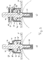
Fig. 1 oberen Seite ist die Welle 23 durch eine Öffnung 31 einer Wand 33 des Gehäuses 11 geführt. Unmittelbar an die Öffnung 31 schließt ein Lagerraum 35 zur Lagerung des aus dem Gehäuse 11 heraustretenden oberen Teils 37 der Welle 23 an. Der Lagerraum 35 ist von einem separaten Gehäuseteil 39 umgeben, welcher mit dem restlichen Gehäuse 11 gasdicht verschweißt ist. Die Welle 23 durchsetzt den Lagerraum 35 vollständig und ist durch eine Öffnung 41 (Fig. 3a ) in einer oberen Wand 43 des separaten Gehäuseteils 39 nach außen geführt. - Außerhalb des Lagerraums 35 ist eine auf Druck vorgespannte Tellerfeder 45 vorgesehen, die eine mittige Öffnung aufweist, durch welche die Welle 23 geführt ist. Die Tellerfeder 45 stützt sich einerseits über eine Keramikscheibe 47 an der oberen Wand 43 des separaten Gehäuseteils 39 und andererseits über eine Scheibe 79 und über einen Sicherungsring 49, der in eine an der Welle 23 ausgebildete, umlaufende Nut eingreift, an der Welle 23 ab. Über das außerhalb des Gehäuses 11, insbesondere außerhalb des separaten Gehäuseteils 39 und jenseits der Tellerfeder 45 liegende Ende des oberen Teils 37 der Welle 23 ist die Welle 23 betätigbar.
- Innerhalb des Lagerraums 35 ist ein von der Tellerfeder 45 beabstandet angeordneter Dichtungsring 51 zur Abdichtung des Gehäuseinneren nach außen vorgesehen. Durch die vorgespannte Tellerfeder 45 wird eine ringförmige Außenumfangsfläche 53 (
Fig. 3a ) eines Absatzes 55 (Fig. 3a ) der Welle 23 gegen eine innere Dichtfläche 54 des Dichtungsrings 51 und eine äußere Dichtfläche 56 gegen einen ringförmigen Wandabschnitt 57 des separaten Gehäuseteils 39 gedrängt. Die Außenumfangsfläche 53 und der Wandabschnitt 57 sowie die innere Dichtfläche 54 und die äußere Dichtfläche 56 sind jeweils um 45° zur Drehachse der Verschlussklappe 17 geneigt, wobei grundsätzlich jedoch jeweils auch andere Neigungswinkel möglich sind. Darüber hinaus bewirkt die beschriebene Ausgestaltung, dass der Dichtungsring 51 zugleich als Gleitlager zur axialen und radialen Lagerung der Welle 23 der Verschlussklappe 17 wirkt. - Der Dichtungsring 51 besitzt im Querschnitt durch eine Seite gesehen eine quadratische Grundform mit abgeschrägten Ecken, wobei eine Normale auf die innere Dichtfläche 54 und eine Normale auf die äußere Dichtfläche 56 zusammenfallen, so dass die beiden Druckpunkte, an denen der Dichtungsring 51 gegen die Welle 23 und das separate Gehäuseteil 39 gedrängt wird, auf einer gemeinsamen Normalen 71 (
Fig. 3b ), bezüglich einer mittleren Umfangslinie 73 (Fig. 3b ) des Dichtungsrings 51 gegenüberliegend angeordnet sind, wodurch eine besonders gute Abdichtung und Lagerung erreicht werden kann. - Die Welle 23 umfasst ferner zwei bezüglich der Drehachse der Verschlussklappe 17 gegenüberliegend angeordnete Mitnehmer 61, die jeweils in eine Winkelausnehmung des Dichtungsringes 51 eingreifen, um den Dichtungsring 51 beim Verdrehen der Welle 37 teilweise mitzudrehen. Die Größe der Winkelausnehmung bestimmt dabei den Winkelbereich, über welchen der Dichtungsring 51 nicht mit der Welle 37 mitdreht.
- Zwischen dem Inneren des Gehäuses 11 und dem Dichtungsring 51 ist eine Keramikscheibe 63 angeordnet, die ebenso wie die bereits vorstehend erwähnte, zwischen der oberen Wand 43 des separaten Gehäuseteils 39 und der Tellerfeder 45 angeordnete Keramikscheibe 47, als Hitzeschild ausgebildet ist, um einen Wärmeübertrag von dem Abgas aus dem Gehäuseinneren an jeweils hinter dem Hitzeschild befindliche Bestandteile des Klappenventils zu verringern. Die Keramikscheibe 63 zwischen dem Gehäuseinneren und dem Dichtungsring 51 ist dabei derart ausgebildet, dass sie zugleich als Lagerbuchse zur radialen Lagerung der Verschlussklappe 17 wirkt.
- Im Gegensatz zu dem Klappenventil gemäß
Fig. 1 wird bei dem Klappenventil gemäßFig. 3a anstelle einer Tellerfeder eine Teleskopfeder 65 verwendet. Ansonsten entspricht die Ausbildung des Klappenventils gemäßFig. 3a jedoch der Ausbildung des Klappenventils gemäßFig. 1 . -
Fig. 3b zeigt ein weiteres Ausführungsbeispiel eines erfindungsgemäßen Klappenventils, wobei jedoch lediglich die Abweichungen dieses Ausführungsbeispiels gegenüber den in denFig. 1 und3 dargestellten Ausführungsbeispielen erläutert werden sollen. Das Ausführungsbeispiel gemäßFig. 3b umfasst anstelle einer Tellerfeder bzw. einer Teleskopfeder eine Schraubenfeder 67. Im Gegensatz zu den in denFig. 1 und3a gezeigten Federn stützt sich die Schraubenfeder 67 zwar an der Welle 23, nicht jedoch an der oberen Wand 43 des separaten Gehäuseteils 39 ab. Vielmehr ist der Innendurchmesser der Schraubenfeder 67 derart gewählt, dass die Schraubenfeder 67 das separate Gehäuseteil 39 umschließt und sich an einem benachbarten Gehäuseabschnitt des Gehäuses 11 abstützt. - Anstelle der vorstehend beschriebenen Federn 45, 65, 67 können beispielsweise auch die in
Fig. 4 gezeigten Federn 75, 77, 79, 81, 83 verwendet werden, wobei die Welle 23 jeweils durch eine Öffnung 69 der Federn 45, 65, 67, 75, 77, 79, 81, 83 geführt ist, und wobei die Federn 75, 77, 79, 81 jeweils am separaten Gehäuseteil 39 und über den Sicherungsring 49, insbesondere ohne eine Scheibe 79, an der Welle 23 abgestützt sind. - Die in
Fig. 4a gezeigte Federspange 75 umfasst zwei im unbelasteten Zustand im Wesentlichen parallel zueinander verlaufende, flächig ausgebildete Schenkel. Durch die flächige Ausbildung der Schenkel kann eine sichere Abstützung nach beiden Seiten, sowohl gegen die Welle 23 als auch gegen den separaten Gehäuseteil 39 gewährleistet werden. Um die Federspange 75 vonFig. 4a unter Druck vorzuspannen, werden die beiden Schenkel an dem offenen Ende der Federspange 75 zusammengedrückt. - Die in
Fig. 4b gezeigte Federspange 75 unterscheidet sich von der inFig. 4a gezeigten Federspange dadurch, dass die beiden Schenkel an dem sonst offenen Ende der Federspange 75 gegeneinander abgestützt sind. Um die Federspange 75 vonFig. 4b unter Druck vorzuspannen, werden die beiden Schenkel mittig zusammengedrückt. - Die in
Fig. 4c gezeigte Feder 81 unterscheidet sich von der inFig. 4b gezeigten Federspange dadurch, dass die beiden Schenkel an dem sonst offenen Ende einer Federspange fest miteinander verbunden sind. -
Fig. 4d zeigt eine Feder 79, die nach Art einer Tellerfeder ausgebildet ist. Die Feder 79 weist bezüglich einer Achse der Öffnung 69 eine rotationssymmetrische Grundform mit zwei gegenüberliegenden Abstützflächen und einem dazwischen angeordneten umlaufenden, nach außen ausgebauchten, federelastischen Bereich, wobei die Rotationssymmetrie durch um die Achse der Öffnung 69 regelmäßig verteilte, im ausgebauchten Bereich ausgebildete Ausnehmungen unterbrochen ist. - Die in
Fig. 4e gezeigte Schenkelfeder 77 umfasst zwei zylindrische Drehfedern, deren freie Enden derart miteinander verbunden sind, dass ein gemeinsamer oberer Schenkel und ein gemeinsamer unterer Schenkel ausgebildet ist, mit denen die Schenkelfeder 77 am separaten Gehäuseteil 39 und über den Sicherungsring 49 an der Welle 23 abstützbar ist. -
Fig. 4f zeigt eine Feder 83, die auf einer unteren Seite symmetrisch um eine Achse verteilt angeordnete Federplättchen umfasst, mit denen die Feder 83 am separaten Gehäuseteil 39 abstützbar ist. Auf einer oberen Seite der Feder 83 sind symmetrisch um die Achse verteilt angeordnete Stützkrallen vorgesehen, die zur Abstützung der Feder 83 an der Welle 23 in eine entsprechende Vertiefung oder Nut der Welle 23 eingreifen. - In den dargestellten Ausführungsbeispielen sind die Federmittel jeweils als Druckfeder ausgeführt. Grundsätzlich ist es jedoch auch möglich, dass die Mittel unter Zug vorgespannt sind. Beispielsweise könnte eine Schraubenfeder unter Zug vorgespannt und mit einem ersten Ende an der oberen Wand des Gehäuses 11 und mit einem zweiten Ende an der Welle 23 befestigt sein.
- Durch die erfindungsgemäße Abstützung der Mittel an dem Gehäuse und der Welle und nicht an der Dichtung wird erreicht, dass die thermische Belastung für die Mittel verringert werden kann. Dieser Effekt kann durch die beabstandete Anordnung der Mittel von der Dichtung und die Anordnung der Mittel außerhalb des separaten Gehäuseteils noch verstärkt werden.
-
- 11
- Gehäuse
- 13
- Fluideinlassöffnung
- 15
- Fluidauslassöffnung
- 17
- Verschlussklappe
- 19
- Flügel
- 21
- Flügel
- 23
- Welle
- 25
- Radiallager
- 27
- unterer Teil von 23
- 29
- Lagergehäuse
- 31
- Öffnung
- 33
- Wand
- 35
- Lagerraum
- 37
- oberer Teil von 23
- 39
- separates Gehäuseteil
- 41
- Öffnung
- 43
- obere Wand
- 45
- Tellerfeder
- 47
- Keramikscheibe
- 49
- Sicherungsring
- 51
- Dichtungs- und Lagerring
- 53
- Außenumfangsfläche
- 54
- innere Dichtfläche
- 55
- Absatz
- 56
- äußere Dichtfläche
- 57
- Wandabschnitt
- 59
- Sicherungsscheibe
- 61
- Mitnehmer
- 63
- Keramikscheibe
- 65
- Teleskopfeder
- 67
- Schraubenfeder
- 69
- Öffnung
- 71
- Normale
- 73
- mittlere Umfangslinie
- 75
- Federspange
- 77
- Schenkelfeder
- 79
- Tellerfeder
- 81
- Federspange
- 83
- Feder
- I
- Drehachse
Claims (13)
- Klappenventil, insbesondere zur Verwendung im Heißbereich von Abgasanlagen für Verbrennungsmotoren, mit einem Gehäuse (11, 39) mit mindestens einer Fluideinlassöffnung (13) und mindestens einer Fluidauslassöffnung (15), einer im Gehäuse (11, 39) drehbar angeordneten Verschlussklappe (17), welche ein Drehübertragungsmittel (23) umfasst, welches durch eine Öffnung (31) in einer Wand (33) des Gehäuses (11, 39) geführt und mit einem außerhalb des Gehäuses (11, 39) vorgesehenen Betätigungselement drehfest verbindbar ist, und einer zwischen Gehäuse (11) und Drehübertragungsmittel (23) wirksamen Dichtung (51) zur Abdichtung des Gehäuseinneren nach außen, wobei in Richtung des Betätigungselements gesehen weiter außerhalb als die Dichtung (51) angeordnete Mittel (45, 65, 67, 75, 77, 81, 83), insbesondere Federmittel, vorgesehen sind, durch welche die Dichtung (51) gegen das Gehäuse (11, 39) und/oder das Drehübertragungsmittel (23) gedrängt wird, und wobei sich die Mittel einerseits an dem Drehübertragungsmittel (23) und andererseits an dem Gehäuse (11, 39) abstützen,
dadurch gekennzeichnet,
dass sich die Mittel (45, 65, 67, 75, 77, 81, 83) nicht an der Dichtung (51) abstützen, dass die Dichtung (51) zugleich als Lagermittel zur radialen Lagerung der Verschlussklappe (17), insbesondere als Gleitlager, ausgebildet ist, wobei das Gehäuse (11, 39) einen separaten Gehäuseteil (39) zur Aufnahme der Dichtung (51) umfasst und die Mittel (45, 65, 67, 75, 77, 81, 83) außerhalb des separaten Gehäuseteils (39) angeordnet sind. - Klappenventil nach Anspruch 1,
dadurch gekennzeichnet,
dass sich die Mittel (45, 65, 67, 75, 77, 81, 83) auf der dem übrigen Gehäuse (11) abgewandten Seite des separaten Gehäuseteils (39) abstützen. - Klappenventil nach Anspruch 1,
dadurch gekennzeichnet,
dass die Mittel (45, 65, 67, 75, 77, 81, 83) den separaten Gehäuseteil (39) umschließen und sich an einem diesem benachbarten Gehäuseabschnitt des Gehäuses (11, 39) abstützen. - Klappenventil nach zumindest einem der vorstehenden Ansprüche,
dadurch gekennzeichnet,
dass sich die Mittel (45, 65, 67, 75, 77, 81, 83) über eine Formschlussverbindung an dem Drehübertragungsmittel (23) abstützen. - Klappenventil nach zumindest einem der vorstehenden Ansprüche,
dadurch gekennzeichnet,
dass die Dichtung (51) zugleich als Lagermittel zur axialen Lagerung der Verschlussklappe (17), insbesondere als Gleitlager, ausgebildet ist. - Klappenventil nach Anspruch 5,
dadurch gekennzeichnet,
dass die Dichtung (51) zur Drehachse der Verschlussklappe (17) geneigte, ringförmige Schrägflächen aufweist, die mit entsprechenden Schrägflächen (53, 57) am Gehäuse (11, 39) und/oder am Drehübertragungsmittel (23) zusammenwirken. - Klappenventil nach Anspruch 6,
dadurch gekennzeichnet,
dass in einem Querschnitt durch eine Seite der Dichtung (51) eine Normale (71) auf eine innere Dichtfläche und eine Normale (71) auf eine äußere Dichtfläche der Dichtung (51) parallel zueinander verlaufen, insbesondere zusammenfallen. - Klappenventil nach zumindest einem der vorstehenden Ansprüche,
dadurch gekennzeichnet,
dass das Drehübertragungsmittel (23) zur Ausbildung einer Dichtfläche einen Absatz (55) aufweist, wobei der Absatz (55) bevorzugt eine zur Drehachse der Verschlussklappe (17) geneigte, ringförmige Außenumfangsfläche (53) aufweist. - Klappenventil nach zumindest einem der vorstehenden Ansprüche,
dadurch gekennzeichnet,
dass zwischen dem Gehäuseinneren und der Dichtung (51) und/oder dem separaten Gehäuseteil (39) und den Mitteln (45, 65, 67, 75, 77, 81, 83) ein Hitzeschild (47, 63), insbesondere aus Keramik, angeordnet ist. - Klappenventil nach Anspruch 9,
dadurch gekennzeichnet,
dass der Hitzeschild (63) zwischen dem Gehäuseinneren und der Dichtung (51) zugleich als Lagermittel zur radialen Lagerung der Verschlussklappe (17), insbesondere als Lagerbuchse, ausgebildet ist. - Klappenventil nach zumindest einem der vorstehenden Ansprüche,
dadurch gekennzeichnet,
dass die Federmittel als Federspange (75), Schenkelfeder (77), Schraubenfeder (67), Teleskopfeder (65) oder Tellerfeder (45) ausgebildet sind. - Klappenventil nach zumindest einem der vorstehenden Ansprüche,
dadurch gekennzeichnet,
dass Mittel (61) vorgesehen sind, durch welche die Dichtung (51) beim Verdrehen der Verschlussklappe (17) nur teilweise mitgedreht wird. - Doppelklappe, insbesondere zur Verwendung im Heißbereich von Abgasanlagen für Verbrennungsmotoren, mit zwei jeweils nach zumindest einem der vorhergehenden Ansprüche ausgebildeten Klappenventilen, welche in Strömungsrichtung hintereinander angeordnet sind.
Applications Claiming Priority (1)
| Application Number | Priority Date | Filing Date | Title |
|---|---|---|---|
| DE202008005992U DE202008005992U1 (de) | 2008-04-30 | 2008-04-30 | Klappenventil |
Publications (3)
| Publication Number | Publication Date |
|---|---|
| EP2113692A1 EP2113692A1 (de) | 2009-11-04 |
| EP2113692B1 EP2113692B1 (de) | 2011-12-14 |
| EP2113692B2 true EP2113692B2 (de) | 2022-09-14 |
Family
ID=39688659
Family Applications (1)
| Application Number | Title | Priority Date | Filing Date |
|---|---|---|---|
| EP09004906.5A Active EP2113692B2 (de) | 2008-04-30 | 2009-04-02 | Klappenventil |
Country Status (3)
| Country | Link |
|---|---|
| EP (1) | EP2113692B2 (de) |
| AT (1) | ATE537391T1 (de) |
| DE (1) | DE202008005992U1 (de) |
Families Citing this family (11)
| Publication number | Priority date | Publication date | Assignee | Title |
|---|---|---|---|---|
| DE102009052423B4 (de) * | 2009-11-10 | 2011-07-28 | Heinrich Gillet GmbH, 67480 | Ventilklappenvorrichtung |
| US9163565B2 (en) | 2010-05-19 | 2015-10-20 | Tenneco Gmbh | Valve flap device |
| DE102012212998B4 (de) * | 2012-07-24 | 2023-09-07 | Friedrich Boysen Gmbh & Co. Kg | Lagersystem für eine Welle |
| DE102012111810B4 (de) | 2012-12-05 | 2015-02-05 | Pierburg Gmbh | Klappenvorrichtung für eine Verbrennungskraftmaschine |
| DE102012111948B4 (de) | 2012-12-07 | 2015-05-28 | Pierburg Gmbh | Klappenvorrichtung für eine Verbrennungskraftmaschine |
| DE102013013387A1 (de) | 2013-03-10 | 2014-09-11 | Kohlhage Automotive GmbH & Co. KG | Lagerung für eine Welle, insbesondere bei einer Ventileinheit, mit einer solchen Lagerung ausgestattete Ventileinheit und Verfahren zur Herstellung |
| DE102013106627B4 (de) | 2013-06-25 | 2015-02-05 | Pierburg Gmbh | Klappenvorrichtung für eine Verbrennungskraftmaschine |
| FR3048048B1 (fr) | 2016-02-22 | 2018-11-30 | Faurecia Systemes D'echappement | Vanne pour une ligne d'echappement de vehicule |
| CN108953624B (zh) * | 2018-08-13 | 2023-08-15 | 四川大学 | 锁子甲式翻板阀 |
| IT202100004703A1 (it) * | 2021-03-01 | 2022-09-01 | Marelli Europe Spa | Valvola a farfalla motorizzata per un condotto di scarico |
| IT202200004115A1 (it) | 2022-03-04 | 2023-09-04 | Marelli Europe Spa | Valvola a farfalla motorizzata e raffreddata per un condotto di scarico |
Citations (3)
| Publication number | Priority date | Publication date | Assignee | Title |
|---|---|---|---|---|
| JPH0791247A (ja) † | 1993-09-24 | 1995-04-04 | Mikuni Corp | デュアルモードマフラのバタフライバルブ |
| US6273119B1 (en) † | 2000-03-06 | 2001-08-14 | Delphi Technologies, Inc. | Exhaust control valve and method of manufacturing same |
| DE19526144B4 (de) † | 1995-07-18 | 2008-10-23 | Pierburg Gmbh | Anordnung einer Drosselklappe |
Family Cites Families (7)
| Publication number | Priority date | Publication date | Assignee | Title |
|---|---|---|---|---|
| DE1179049B (de) * | 1959-07-16 | 1964-10-01 | Zahnradfabrik Friedrichshafen | Auspuffmotorbremse, bestehend aus einer Bremsklappe, die eine durchgehende Bohrung zur Aufnahme einer Klappenwelle aufweist, und aus einem ungeteilten Gehaeuse |
| ZA803042B (en) * | 1979-08-08 | 1981-05-27 | Krupp Polysius Ag | A pendulum flap |
| IT220044Z2 (it) * | 1990-07-09 | 1993-06-09 | Fasani Spa | Valvola a farfalla per l'itercettazione di regolazione di fluidi |
| US5988589A (en) * | 1996-07-17 | 1999-11-23 | Mowill; R. Jan | Air valve assembly including split-shaft and seal arrangement |
| DE10329336A1 (de) | 2003-06-30 | 2005-01-20 | Friedrich Boysen Gmbh & Co. Kg | Klappenventil |
| DE112005001467B4 (de) * | 2004-07-07 | 2015-04-02 | Faurecia Abgastechnik Gmbh | Klappenventil für die Abgasanlage eines Kraftfahrzeuges |
| DE102006048713A1 (de) * | 2006-10-14 | 2008-04-17 | Daimler Ag | Ventilvorrichtung |
-
2008
- 2008-04-30 DE DE202008005992U patent/DE202008005992U1/de not_active Expired - Lifetime
-
2009
- 2009-04-02 AT AT09004906T patent/ATE537391T1/de active
- 2009-04-02 EP EP09004906.5A patent/EP2113692B2/de active Active
Patent Citations (3)
| Publication number | Priority date | Publication date | Assignee | Title |
|---|---|---|---|---|
| JPH0791247A (ja) † | 1993-09-24 | 1995-04-04 | Mikuni Corp | デュアルモードマフラのバタフライバルブ |
| DE19526144B4 (de) † | 1995-07-18 | 2008-10-23 | Pierburg Gmbh | Anordnung einer Drosselklappe |
| US6273119B1 (en) † | 2000-03-06 | 2001-08-14 | Delphi Technologies, Inc. | Exhaust control valve and method of manufacturing same |
Also Published As
| Publication number | Publication date |
|---|---|
| ATE537391T1 (de) | 2011-12-15 |
| EP2113692A1 (de) | 2009-11-04 |
| DE202008005992U1 (de) | 2008-08-14 |
| EP2113692B1 (de) | 2011-12-14 |
Similar Documents
| Publication | Publication Date | Title |
|---|---|---|
| EP2113692B2 (de) | Klappenventil | |
| EP1493951B1 (de) | Klappenventil | |
| EP2726719B1 (de) | Ventilvorrichtung zur regelung eines abgasstroms einer verbrennungskraftmaschine | |
| EP2609319B1 (de) | Abgasrückführventil für eine verbrennungskraftmaschine | |
| DE102017202137B4 (de) | Klappeneinrichtung zum Öffnen und Schließen eines Wastegatekanals in einem Turbinengehäuse eines Turboladers sowie Turbolader | |
| EP1771653B1 (de) | Ventil für den einsatz in einer kraftstoffführenden leitung eines kraftfahrzeuges | |
| WO1996021815A1 (de) | Absperr- oder drosselventil mit drehbarer ventilklappe | |
| DE102011077766A1 (de) | Betätigungseinrichtung für ein Abgasstrom-Steuerelement eines Abgasturboladers | |
| EP2929166A1 (de) | Klappenvorrichtung für eine verbrennungskraftmaschine | |
| EP2445605A1 (de) | Filtereinrichtung | |
| EP2929165B1 (de) | Klappenvorrichtung für eine verbrennungskraftmaschine | |
| EP2249067A1 (de) | Klappenscheibenventil | |
| DE112020003543T5 (de) | Extern befestigtes in-line-Abgasventil | |
| WO2006003017A1 (de) | Klappenventil für die abgasanlage eines kraftfahrzeuges | |
| EP3551867B1 (de) | Klappenvorrichtung | |
| DE102012100769A1 (de) | Abgaswegeventil | |
| EP2707590B1 (de) | Ventilvorrichtung für eine verbrennungskraftmaschine | |
| DE102011107413A1 (de) | Drehschieberventil, insbesondere zum Verbinden eines Abgasturboladers mit einer Brennkraftmaschine, sowie Abgaskrümmerbaugruppe | |
| WO2014121986A1 (de) | Ventileinheit für ein wastegatesystem und abgasturbolader | |
| EP3705696B1 (de) | Klappenvorrichtung für eine verbrennungskraftmaschine | |
| EP3714154B1 (de) | Abgasventil für eine verbrennungskraftmaschine | |
| EP3227541B1 (de) | Klappenvorrichtung für eine verbrennungskraftmaschine | |
| EP4062088B1 (de) | Drehventil | |
| DE102005053860B4 (de) | Drosselklappenvorrichtung für Hochtemperaturanwendungen in Verbrennungskraftmaschinen | |
| DE102014207671B4 (de) | Abgasturbolader mit einem Wastegate-Ventil |
Legal Events
| Date | Code | Title | Description |
|---|---|---|---|
| PUAI | Public reference made under article 153(3) epc to a published international application that has entered the european phase |
Free format text: ORIGINAL CODE: 0009012 |
|
| AK | Designated contracting states |
Kind code of ref document: A1 Designated state(s): AT BE BG CH CY CZ DE DK EE ES FI FR GB GR HR HU IE IS IT LI LT LU LV MC MK MT NL NO PL PT RO SE SI SK TR |
|
| 17P | Request for examination filed |
Effective date: 20091222 |
|
| 17Q | First examination report despatched |
Effective date: 20100122 |
|
| GRAP | Despatch of communication of intention to grant a patent |
Free format text: ORIGINAL CODE: EPIDOSNIGR1 |
|
| GRAS | Grant fee paid |
Free format text: ORIGINAL CODE: EPIDOSNIGR3 |
|
| GRAA | (expected) grant |
Free format text: ORIGINAL CODE: 0009210 |
|
| AK | Designated contracting states |
Kind code of ref document: B1 Designated state(s): AT BE BG CH CY CZ DE DK EE ES FI FR GB GR HR HU IE IS IT LI LT LU LV MC MK MT NL NO PL PT RO SE SI SK TR |
|
| REG | Reference to a national code |
Ref country code: GB Ref legal event code: FG4D Free format text: NOT ENGLISH |
|
| REG | Reference to a national code |
Ref country code: CH Ref legal event code: EP |
|
| REG | Reference to a national code |
Ref country code: IE Ref legal event code: FG4D |
|
| REG | Reference to a national code |
Ref country code: DE Ref legal event code: R096 Ref document number: 502009002142 Country of ref document: DE Effective date: 20120308 |
|
| REG | Reference to a national code |
Ref country code: NL Ref legal event code: VDEP Effective date: 20111214 |
|
| PG25 | Lapsed in a contracting state [announced via postgrant information from national office to epo] |
Ref country code: LT Free format text: LAPSE BECAUSE OF FAILURE TO SUBMIT A TRANSLATION OF THE DESCRIPTION OR TO PAY THE FEE WITHIN THE PRESCRIBED TIME-LIMIT Effective date: 20111214 Ref country code: NO Free format text: LAPSE BECAUSE OF FAILURE TO SUBMIT A TRANSLATION OF THE DESCRIPTION OR TO PAY THE FEE WITHIN THE PRESCRIBED TIME-LIMIT Effective date: 20120314 |
|
| LTIE | Lt: invalidation of european patent or patent extension |
Effective date: 20111214 |
|
| PG25 | Lapsed in a contracting state [announced via postgrant information from national office to epo] |
Ref country code: LV Free format text: LAPSE BECAUSE OF FAILURE TO SUBMIT A TRANSLATION OF THE DESCRIPTION OR TO PAY THE FEE WITHIN THE PRESCRIBED TIME-LIMIT Effective date: 20111214 Ref country code: HR Free format text: LAPSE BECAUSE OF FAILURE TO SUBMIT A TRANSLATION OF THE DESCRIPTION OR TO PAY THE FEE WITHIN THE PRESCRIBED TIME-LIMIT Effective date: 20111214 Ref country code: GR Free format text: LAPSE BECAUSE OF FAILURE TO SUBMIT A TRANSLATION OF THE DESCRIPTION OR TO PAY THE FEE WITHIN THE PRESCRIBED TIME-LIMIT Effective date: 20120315 Ref country code: NL Free format text: LAPSE BECAUSE OF FAILURE TO SUBMIT A TRANSLATION OF THE DESCRIPTION OR TO PAY THE FEE WITHIN THE PRESCRIBED TIME-LIMIT Effective date: 20111214 Ref country code: SE Free format text: LAPSE BECAUSE OF FAILURE TO SUBMIT A TRANSLATION OF THE DESCRIPTION OR TO PAY THE FEE WITHIN THE PRESCRIBED TIME-LIMIT Effective date: 20111214 Ref country code: SI Free format text: LAPSE BECAUSE OF FAILURE TO SUBMIT A TRANSLATION OF THE DESCRIPTION OR TO PAY THE FEE WITHIN THE PRESCRIBED TIME-LIMIT Effective date: 20111214 |
|
| PG25 | Lapsed in a contracting state [announced via postgrant information from national office to epo] |
Ref country code: CY Free format text: LAPSE BECAUSE OF FAILURE TO SUBMIT A TRANSLATION OF THE DESCRIPTION OR TO PAY THE FEE WITHIN THE PRESCRIBED TIME-LIMIT Effective date: 20111214 |
|
| REG | Reference to a national code |
Ref country code: IE Ref legal event code: FD4D |
|
| PG25 | Lapsed in a contracting state [announced via postgrant information from national office to epo] |
Ref country code: CZ Free format text: LAPSE BECAUSE OF FAILURE TO SUBMIT A TRANSLATION OF THE DESCRIPTION OR TO PAY THE FEE WITHIN THE PRESCRIBED TIME-LIMIT Effective date: 20111214 Ref country code: SK Free format text: LAPSE BECAUSE OF FAILURE TO SUBMIT A TRANSLATION OF THE DESCRIPTION OR TO PAY THE FEE WITHIN THE PRESCRIBED TIME-LIMIT Effective date: 20111214 Ref country code: IS Free format text: LAPSE BECAUSE OF FAILURE TO SUBMIT A TRANSLATION OF THE DESCRIPTION OR TO PAY THE FEE WITHIN THE PRESCRIBED TIME-LIMIT Effective date: 20120414 Ref country code: BG Free format text: LAPSE BECAUSE OF FAILURE TO SUBMIT A TRANSLATION OF THE DESCRIPTION OR TO PAY THE FEE WITHIN THE PRESCRIBED TIME-LIMIT Effective date: 20120314 Ref country code: EE Free format text: LAPSE BECAUSE OF FAILURE TO SUBMIT A TRANSLATION OF THE DESCRIPTION OR TO PAY THE FEE WITHIN THE PRESCRIBED TIME-LIMIT Effective date: 20111214 Ref country code: IE Free format text: LAPSE BECAUSE OF FAILURE TO SUBMIT A TRANSLATION OF THE DESCRIPTION OR TO PAY THE FEE WITHIN THE PRESCRIBED TIME-LIMIT Effective date: 20111214 |
|
| PG25 | Lapsed in a contracting state [announced via postgrant information from national office to epo] |
Ref country code: RO Free format text: LAPSE BECAUSE OF FAILURE TO SUBMIT A TRANSLATION OF THE DESCRIPTION OR TO PAY THE FEE WITHIN THE PRESCRIBED TIME-LIMIT Effective date: 20111214 Ref country code: PL Free format text: LAPSE BECAUSE OF FAILURE TO SUBMIT A TRANSLATION OF THE DESCRIPTION OR TO PAY THE FEE WITHIN THE PRESCRIBED TIME-LIMIT Effective date: 20111214 Ref country code: PT Free format text: LAPSE BECAUSE OF FAILURE TO SUBMIT A TRANSLATION OF THE DESCRIPTION OR TO PAY THE FEE WITHIN THE PRESCRIBED TIME-LIMIT Effective date: 20120416 |
|
| PLBI | Opposition filed |
Free format text: ORIGINAL CODE: 0009260 |
|
| PLAX | Notice of opposition and request to file observation + time limit sent |
Free format text: ORIGINAL CODE: EPIDOSNOBS2 |
|
| 26 | Opposition filed |
Opponent name: TENNECO GMBH Effective date: 20120914 |
|
| BERE | Be: lapsed |
Owner name: FRIEDRICH BOYSEN G.M.B.H. & CO. KG Effective date: 20120430 |
|
| PG25 | Lapsed in a contracting state [announced via postgrant information from national office to epo] |
Ref country code: DK Free format text: LAPSE BECAUSE OF FAILURE TO SUBMIT A TRANSLATION OF THE DESCRIPTION OR TO PAY THE FEE WITHIN THE PRESCRIBED TIME-LIMIT Effective date: 20111214 |
|
| PG25 | Lapsed in a contracting state [announced via postgrant information from national office to epo] |
Ref country code: MC Free format text: LAPSE BECAUSE OF NON-PAYMENT OF DUE FEES Effective date: 20120430 Ref country code: IT Free format text: LAPSE BECAUSE OF FAILURE TO SUBMIT A TRANSLATION OF THE DESCRIPTION OR TO PAY THE FEE WITHIN THE PRESCRIBED TIME-LIMIT Effective date: 20111214 |
|
| REG | Reference to a national code |
Ref country code: DE Ref legal event code: R026 Ref document number: 502009002142 Country of ref document: DE Effective date: 20120914 |
|
| PG25 | Lapsed in a contracting state [announced via postgrant information from national office to epo] |
Ref country code: BE Free format text: LAPSE BECAUSE OF NON-PAYMENT OF DUE FEES Effective date: 20120430 |
|
| PG25 | Lapsed in a contracting state [announced via postgrant information from national office to epo] |
Ref country code: MK Free format text: LAPSE BECAUSE OF FAILURE TO SUBMIT A TRANSLATION OF THE DESCRIPTION OR TO PAY THE FEE WITHIN THE PRESCRIBED TIME-LIMIT Effective date: 20111214 |
|
| PG25 | Lapsed in a contracting state [announced via postgrant information from national office to epo] |
Ref country code: ES Free format text: LAPSE BECAUSE OF FAILURE TO SUBMIT A TRANSLATION OF THE DESCRIPTION OR TO PAY THE FEE WITHIN THE PRESCRIBED TIME-LIMIT Effective date: 20120325 |
|
| PLBB | Reply of patent proprietor to notice(s) of opposition received |
Free format text: ORIGINAL CODE: EPIDOSNOBS3 |
|
| PG25 | Lapsed in a contracting state [announced via postgrant information from national office to epo] |
Ref country code: FI Free format text: LAPSE BECAUSE OF FAILURE TO SUBMIT A TRANSLATION OF THE DESCRIPTION OR TO PAY THE FEE WITHIN THE PRESCRIBED TIME-LIMIT Effective date: 20111214 |
|
| PG25 | Lapsed in a contracting state [announced via postgrant information from national office to epo] |
Ref country code: MT Free format text: LAPSE BECAUSE OF FAILURE TO SUBMIT A TRANSLATION OF THE DESCRIPTION OR TO PAY THE FEE WITHIN THE PRESCRIBED TIME-LIMIT Effective date: 20111214 |
|
| REG | Reference to a national code |
Ref country code: CH Ref legal event code: PL |
|
| PG25 | Lapsed in a contracting state [announced via postgrant information from national office to epo] |
Ref country code: LI Free format text: LAPSE BECAUSE OF NON-PAYMENT OF DUE FEES Effective date: 20130430 Ref country code: CH Free format text: LAPSE BECAUSE OF NON-PAYMENT OF DUE FEES Effective date: 20130430 |
|
| PG25 | Lapsed in a contracting state [announced via postgrant information from national office to epo] |
Ref country code: TR Free format text: LAPSE BECAUSE OF FAILURE TO SUBMIT A TRANSLATION OF THE DESCRIPTION OR TO PAY THE FEE WITHIN THE PRESCRIBED TIME-LIMIT Effective date: 20111214 |
|
| PG25 | Lapsed in a contracting state [announced via postgrant information from national office to epo] |
Ref country code: LU Free format text: LAPSE BECAUSE OF NON-PAYMENT OF DUE FEES Effective date: 20120402 |
|
| PG25 | Lapsed in a contracting state [announced via postgrant information from national office to epo] |
Ref country code: HU Free format text: LAPSE BECAUSE OF FAILURE TO SUBMIT A TRANSLATION OF THE DESCRIPTION OR TO PAY THE FEE WITHIN THE PRESCRIBED TIME-LIMIT Effective date: 20090402 |
|
| REG | Reference to a national code |
Ref country code: AT Ref legal event code: MM01 Ref document number: 537391 Country of ref document: AT Kind code of ref document: T Effective date: 20140402 |
|
| PG25 | Lapsed in a contracting state [announced via postgrant information from national office to epo] |
Ref country code: AT Free format text: LAPSE BECAUSE OF NON-PAYMENT OF DUE FEES Effective date: 20140402 |
|
| REG | Reference to a national code |
Ref country code: FR Ref legal event code: PLFP Year of fee payment: 8 |
|
| APBM | Appeal reference recorded |
Free format text: ORIGINAL CODE: EPIDOSNREFNO |
|
| APBP | Date of receipt of notice of appeal recorded |
Free format text: ORIGINAL CODE: EPIDOSNNOA2O |
|
| APAH | Appeal reference modified |
Free format text: ORIGINAL CODE: EPIDOSCREFNO |
|
| APBQ | Date of receipt of statement of grounds of appeal recorded |
Free format text: ORIGINAL CODE: EPIDOSNNOA3O |
|
| REG | Reference to a national code |
Ref country code: FR Ref legal event code: PLFP Year of fee payment: 9 |
|
| REG | Reference to a national code |
Ref country code: FR Ref legal event code: PLFP Year of fee payment: 10 |
|
| APBU | Appeal procedure closed |
Free format text: ORIGINAL CODE: EPIDOSNNOA9O |
|
| PLAY | Examination report in opposition despatched + time limit |
Free format text: ORIGINAL CODE: EPIDOSNORE2 |
|
| PLBC | Reply to examination report in opposition received |
Free format text: ORIGINAL CODE: EPIDOSNORE3 |
|
| PLAY | Examination report in opposition despatched + time limit |
Free format text: ORIGINAL CODE: EPIDOSNORE2 |
|
| PLBC | Reply to examination report in opposition received |
Free format text: ORIGINAL CODE: EPIDOSNORE3 |
|
| PUAH | Patent maintained in amended form |
Free format text: ORIGINAL CODE: 0009272 |
|
| STAA | Information on the status of an ep patent application or granted ep patent |
Free format text: STATUS: PATENT MAINTAINED AS AMENDED |
|
| 27A | Patent maintained in amended form |
Effective date: 20220914 |
|
| AK | Designated contracting states |
Kind code of ref document: B2 Designated state(s): AT BE BG CH CY CZ DE DK EE ES FI FR GB GR HR HU IE IS IT LI LT LU LV MC MK MT NL NO PL PT RO SE SI SK TR |
|
| REG | Reference to a national code |
Ref country code: DE Ref legal event code: R102 Ref document number: 502009002142 Country of ref document: DE |
|
| PGFP | Annual fee paid to national office [announced via postgrant information from national office to epo] |
Ref country code: DE Payment date: 20250625 Year of fee payment: 17 |
|
| PGFP | Annual fee paid to national office [announced via postgrant information from national office to epo] |
Ref country code: GB Payment date: 20250418 Year of fee payment: 17 |
|
| PGFP | Annual fee paid to national office [announced via postgrant information from national office to epo] |
Ref country code: FR Payment date: 20250424 Year of fee payment: 17 |