EP3705696B1 - Klappenvorrichtung für eine verbrennungskraftmaschine - Google Patents
Klappenvorrichtung für eine verbrennungskraftmaschine Download PDFInfo
- Publication number
- EP3705696B1 EP3705696B1 EP20160373.5A EP20160373A EP3705696B1 EP 3705696 B1 EP3705696 B1 EP 3705696B1 EP 20160373 A EP20160373 A EP 20160373A EP 3705696 B1 EP3705696 B1 EP 3705696B1
- Authority
- EP
- European Patent Office
- Prior art keywords
- flap
- housing
- inlet
- combustion engine
- internal combustion
- Prior art date
- Legal status (The legal status is an assumption and is not a legal conclusion. Google has not performed a legal analysis and makes no representation as to the accuracy of the status listed.)
- Active
Links
Images
Classifications
-
- F—MECHANICAL ENGINEERING; LIGHTING; HEATING; WEAPONS; BLASTING
- F02—COMBUSTION ENGINES; HOT-GAS OR COMBUSTION-PRODUCT ENGINE PLANTS
- F02B—INTERNAL-COMBUSTION PISTON ENGINES; COMBUSTION ENGINES IN GENERAL
- F02B37/00—Engines characterised by provision of pumps driven at least for part of the time by exhaust
- F02B37/12—Control of the pumps
- F02B37/18—Control of the pumps by bypassing exhaust from the inlet to the outlet of turbine or to the atmosphere
- F02B37/183—Arrangements of bypass valves or actuators therefor
-
- F—MECHANICAL ENGINEERING; LIGHTING; HEATING; WEAPONS; BLASTING
- F02—COMBUSTION ENGINES; HOT-GAS OR COMBUSTION-PRODUCT ENGINE PLANTS
- F02M—SUPPLYING COMBUSTION ENGINES IN GENERAL WITH COMBUSTIBLE MIXTURES OR CONSTITUENTS THEREOF
- F02M26/00—Engine-pertinent apparatus for adding exhaust gases to combustion-air, main fuel or fuel-air mixture, e.g. by exhaust gas recirculation [EGR] systems
- F02M26/13—Arrangement or layout of EGR passages, e.g. in relation to specific engine parts or for incorporation of accessories
- F02M26/22—Arrangement or layout of EGR passages, e.g. in relation to specific engine parts or for incorporation of accessories with coolers in the recirculation passage
- F02M26/23—Layout, e.g. schematics
- F02M26/25—Layout, e.g. schematics with coolers having bypasses
- F02M26/26—Layout, e.g. schematics with coolers having bypasses characterised by details of the bypass valve
-
- F—MECHANICAL ENGINEERING; LIGHTING; HEATING; WEAPONS; BLASTING
- F02—COMBUSTION ENGINES; HOT-GAS OR COMBUSTION-PRODUCT ENGINE PLANTS
- F02M—SUPPLYING COMBUSTION ENGINES IN GENERAL WITH COMBUSTIBLE MIXTURES OR CONSTITUENTS THEREOF
- F02M26/00—Engine-pertinent apparatus for adding exhaust gases to combustion-air, main fuel or fuel-air mixture, e.g. by exhaust gas recirculation [EGR] systems
- F02M26/65—Constructional details of EGR valves
- F02M26/70—Flap valves; Rotary valves; Sliding valves; Resilient valves
-
- F—MECHANICAL ENGINEERING; LIGHTING; HEATING; WEAPONS; BLASTING
- F02—COMBUSTION ENGINES; HOT-GAS OR COMBUSTION-PRODUCT ENGINE PLANTS
- F02M—SUPPLYING COMBUSTION ENGINES IN GENERAL WITH COMBUSTIBLE MIXTURES OR CONSTITUENTS THEREOF
- F02M26/00—Engine-pertinent apparatus for adding exhaust gases to combustion-air, main fuel or fuel-air mixture, e.g. by exhaust gas recirculation [EGR] systems
- F02M26/65—Constructional details of EGR valves
- F02M26/71—Multi-way valves
-
- F—MECHANICAL ENGINEERING; LIGHTING; HEATING; WEAPONS; BLASTING
- F02—COMBUSTION ENGINES; HOT-GAS OR COMBUSTION-PRODUCT ENGINE PLANTS
- F02M—SUPPLYING COMBUSTION ENGINES IN GENERAL WITH COMBUSTIBLE MIXTURES OR CONSTITUENTS THEREOF
- F02M26/00—Engine-pertinent apparatus for adding exhaust gases to combustion-air, main fuel or fuel-air mixture, e.g. by exhaust gas recirculation [EGR] systems
- F02M26/65—Constructional details of EGR valves
- F02M26/72—Housings
-
- F—MECHANICAL ENGINEERING; LIGHTING; HEATING; WEAPONS; BLASTING
- F16—ENGINEERING ELEMENTS AND UNITS; GENERAL MEASURES FOR PRODUCING AND MAINTAINING EFFECTIVE FUNCTIONING OF MACHINES OR INSTALLATIONS; THERMAL INSULATION IN GENERAL
- F16K—VALVES; TAPS; COCKS; ACTUATING-FLOATS; DEVICES FOR VENTING OR AERATING
- F16K11/00—Multiple-way valves, e.g. mixing valves; Pipe fittings incorporating such valves
- F16K11/02—Multiple-way valves, e.g. mixing valves; Pipe fittings incorporating such valves with all movable sealing faces moving as one unit
- F16K11/04—Multiple-way valves, e.g. mixing valves; Pipe fittings incorporating such valves with all movable sealing faces moving as one unit comprising only lift valves
- F16K11/052—Multiple-way valves, e.g. mixing valves; Pipe fittings incorporating such valves with all movable sealing faces moving as one unit comprising only lift valves with pivoted closure members, e.g. butterfly valves
- F16K11/0525—Multiple-way valves, e.g. mixing valves; Pipe fittings incorporating such valves with all movable sealing faces moving as one unit comprising only lift valves with pivoted closure members, e.g. butterfly valves the closure members being pivoted around an essentially central axis
-
- Y—GENERAL TAGGING OF NEW TECHNOLOGICAL DEVELOPMENTS; GENERAL TAGGING OF CROSS-SECTIONAL TECHNOLOGIES SPANNING OVER SEVERAL SECTIONS OF THE IPC; TECHNICAL SUBJECTS COVERED BY FORMER USPC CROSS-REFERENCE ART COLLECTIONS [XRACs] AND DIGESTS
- Y02—TECHNOLOGIES OR APPLICATIONS FOR MITIGATION OR ADAPTATION AGAINST CLIMATE CHANGE
- Y02T—CLIMATE CHANGE MITIGATION TECHNOLOGIES RELATED TO TRANSPORTATION
- Y02T10/00—Road transport of goods or passengers
- Y02T10/10—Internal combustion engine [ICE] based vehicles
- Y02T10/12—Improving ICE efficiencies
Definitions
- the invention relates to a flap device for an internal combustion engine with a flap housing in which an inlet and two outlets are formed, and a flap body which has two flap halves and which is arranged on a shaft which is rotatably mounted in the flap housing and from which extends on both sides the two flap halves extend, with a first stop and a second stop being formed in the flap housing, against which one flap half of the flap body rests in a first end position of the flap body and a third stop and a fourth stop are formed, against which in a second end position of the Flap body rests in each case a flap half of the flap body.
- flap devices are used in particular as 3/2-way bypass valves in the exhaust gas area of vehicles.
- the flap devices are used, for example, in an exhaust gas recirculation duct to direct the exhaust gas flow either to an exhaust gas cooler or around the exhaust gas cooler in order to reduce pollutant emissions through faster heating during the cold start phase.
- Such flaps can also be used to bypass the turbine of turbochargers.
- Such a bypass valve is, for example, from WO 2017/174121 A1 famous.
- the valve body arranged on the shaft can be rotated with the shaft into two end positions, with a fluidic connection between the inlet and one of the outlets being created in each of the two end positions, while the passage to the respective other outlet is closed by the valve body.
- the flap body rests against the channel walls of the housing.
- a flap valve which is used with a flap housing between two shells of a connection housing, and in which valve seat surfaces are formed on the housing.
- More devices are off DE 10 2008 048912 A1 , DE 10 2013 111215 A1 , DE 10 2005 012842 A1 , EP 1 443 191 A2 , U.S. 2001/047834 A1 and DE 77 16 337 U1 famous.
- the task is therefore to create a flap device for an internal combustion engine, which is designed as a 3/2-way valve, which ensures a tight seal in both end positions of the flap body and can be installed as independently as possible from the connection housing.
- the flap halves in their two end positions are each perpendicular to valve seat surfaces with their entire outer peripheral area which are formed on the stops, the flap halves extending essentially parallel to the valve seat surfaces in the end positions, the flap body having a first dimensionally stable flap plate and a second dimensionally stable flap plate, between which a flexible sealing element is clamped, which extends over the circumference of the two flap plates protrudes radially, so that an outer surface of the sealing element forms the outer peripheral area of the cap body, which rests against the valve seat surfaces in the two end positions and wherein the flap housing is designed as a cylindrical plug-in housing which is connected to the flap body and the shaft in the axial direction of the shaft and the cylindrical plug housing is inserted into a receiving opening of a connection housing, so that an inlet channel of the connection housing opens into the inlet of the flap housing and two outlet channels of the connection housing extend from the outlets of the flap housing ensures that leakage in both end positions between the flap body and the valve seat surfaces are minimized in both end positions.
- the support takes place up to the passage of the shaft.
- the high degree of tightness is ensured by the flat, axial stop to the valve seat, which works in a similar way to closing a door on a door frame.
- the outer peripheral area is understood to be the area of each flap half that is not directed directly towards the opposite flap half, so that the two flap halves together form a closed, overlying outer peripheral area.
- the flap device is thus designed as a plug-in valve, which can be used in any connection housing. Nevertheless, it includes the necessary flap bearings as well as the valve seat surfaces and, if necessary, the actuator. These components can be used completely pre-assembled in a corresponding housing.
- the tightness in the closed state can also be increased, since the flap body does not have to be installed in a large housing that is difficult to access. Such a plugged-in housing can be clearly marked accordingly are manufactured to smaller tolerances, which also increases the achievable tightness. Due to the flexible sealing element, slight unevenness can be compensated for by deformation. Furthermore, an increased closing pressure and tolerance compensation can be applied through targeted over-tightening without jeopardizing the stability of the flap body. In this way, the tightness can be additionally increased.
- the outer peripheral area of the flap halves formed by the outer surfaces of the sealing element projecting radially beyond the flap plates preferably lies flat on the associated valve seat surface shaped to correspond to the outer peripheral area of the flap body. This larger contact surface increases the flow resistance, which increases the tightness of the closure.
- the inlet and the two outlets are offset from one another in the direction of rotation, with the inlet being arranged between the two outlets. This enables simple switching between the two gas paths due to a very small angle of rotation to be traversed.
- the flexible sealing element is a sheet metal spring plate that is easy to manufacture and has high resistance to thermal, chemical and mechanical stress.
- the two flap plates and the flexible sealing element are preferably fastened to one another by means of a screw connection. Such an attachment is easy to produce and also allows individual flap parts to be replaced.
- a simple production with low flow resistances due to existing deflections is achieved if the first outlet is offset from the inlet by 90° in the direction of rotation and the inlet is arranged offset by 90° to the second outlet.
- the inlet and the outlets each extend over a 90° angle of rotation of the flap body.
- approximately the same channel diameters can be retained in a cylindrical plug-in valve, which reduces the flow resistance.
- the flap housing is preferably closed radially opposite to the inlet, whereby the rigidity of the housing is increased and flows around the flap when shifting are largely prevented.
- the flap housing preferably has a base and a cover part on which webs are formed which form the stops with four struts which connect the base to the cover part.
- a flap housing of this type can be produced particularly easily and inexpensively and is light in weight.
- a flap device for an internal combustion engine is thus created which, as a 3/2-way valve, closes the respective outlet very tightly in both end positions.
- this flap device can be designed as a cylindrical plug-in valve, which can be adapted to any connection housing. The flow resistance in the flap housing is also kept low.
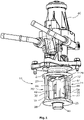
- figure 1 shows a perspective view of a flap device according to the invention.
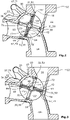
- figure 2 shows the flap device according to the invention in the axial direction of the shaft in a sectional representation in a first end position.
- figure 3 shows the flap device according to the invention in the axial direction of the shaft in a sectional view in a second end position.
- the flap device according to the invention consists of a flap housing 10, which is cylindrical in the present exemplary embodiment and is designed as a plug-in housing that can be pushed into a connection housing 12 in the axial direction.
- a central inlet duct 14 as well as a first outlet duct 16 and a second outlet duct 18 are formed on the connection housing 12, which, viewed from the inlet duct 14, are opposite to one another from a receiving opening 20 for the valve housing 10 and are offset on both sides in the direction of rotation by 90° to the inlet duct 14 extend into the continuing connection housing 12 .
- the flap housing 10 has an inlet 22 corresponding to the inlet duct 14 and into which the inlet duct 14 opens, as well as a first outlet 24 which opens into the first outlet duct 16 and a second outlet 26 which opens into the second outlet duct 18 .
- the flap housing 10 consists of a cover part 27 and a base 28, which are circular and between which four struts 30, 31, 32, 34 extend, which extend from the base 28 to the cover part 27. Webs 29 adjoin these struts 30, 31, 32, 34, which extend radially inward along the base 28 and the cover part 27.
- the stops 48, 50, 52, 54 each have a valve seat surface 56, 58, 60, 62, with the two valve seat surfaces 56, 58, 60, 62 pointing away from the outlets 24, 26, viewed in the circumferential direction, so that the respective acting valve seat surfaces 56, 58, 60, 62 are offset by 180 ° to each other and each valve seat surface 56, 58, 60, 62 to the next valve seat surface 58, 60, 62, 56 is arranged offset by 90 °.
- the flap body 44 is divided by the shaft 42 into two equal flap halves 64, 66, each flap half 64, 66 interacting with the two valve seat surfaces 56, 58, 60, 62, between which it is rotated by the flap halves 64, 66 with its Outer peripheral portion 67 perpendicular to the valve seat surfaces 56, 58, 60, 62 rest.
- the flap half 64, 66 also corresponds in shape to the valve seat surfaces 56, 58, 60, 62, the inner circumference of which is selected to be only slightly smaller than the outer circumference of the flap body 44. In the end positions, the flap body 44 extends parallel to the valve seat surfaces 56 , 58, 60, 62.
- the flap halves 64, 66 are approximately rectangular in shape with rounded corners and have a layered structure consisting of a first dimensionally stable flap plate 68 and a second dimensionally stable flap plate 70, between which there is a flexible sealing element designed as a spring steel plate 72 is arranged, which protrudes radially evenly over the peripheral edge of the flap plates 68, 70, so that two flexible U-shaped outer surfaces 74 delimit the flap body 44, which form the outer peripheral region 67 of the flap halves 64, 66.
- the two flap plates 68, 70 can be inserted with the interposition of the Sealing element 72 are connected to each other by screws or rivets or by welding.
- the two flexible U-shaped outer surfaces 74 rest perpendicularly on the valve seat surfaces 56, 58, 60, 62 in the end positions of the flap body 44.
- an exhaust gas flow can flow from the inlet duct 14 to the inlet 22 and past the flap body 44 to the first outlet duct 16, while the second outlet duct 18 is covered by the flap body 44, with a high degree of tightness being ensured by the surrounding and vertical contact of the two outer surfaces 74 of the flexible Sealing element 72 on the valve seat surfaces 56, 60 is achieved.
- the flap body 44 When the shaft 42 is actuated, the flap body 44 is turned counterclockwise away from the valve seat surfaces 56, 60 until, after about 90°, the opposite side of the outer surfaces 74 rests perpendicularly on the valve seat surfaces 58, 62, with the outer surface 74 of the first flap half 64 rests against the valve seat surface 58 at the third stop 50 and the outer surface 74 of the second flap half 66 rests against the valve seat surface 62 at the fourth stop 54 . Accordingly, in this second end position, the exhaust gas flow passes from the inlet port 14 via the inlet 22 of the flap device along the surface of the flap body 44 to the second outlet 26 and into the second outlet port 18.
- the invention is not limited to the exemplary embodiment described, but that various constructive changes are possible.
- the flap body and the valve seat surfaces can also be round or oval, in which case the shape of the struts and webs would have to be adapted to the shape of the flap in order to form a circumferential valve seat.
- An annular or U-shaped sealing element can also be clamped between the flap plates.
Landscapes
- Engineering & Computer Science (AREA)
- General Engineering & Computer Science (AREA)
- Mechanical Engineering (AREA)
- Chemical & Material Sciences (AREA)
- Combustion & Propulsion (AREA)
- Lift Valve (AREA)
Description
- Die Erfindung betrifft eine Klappenvorrichtung für eine Verbrennungskraftmaschine mit einem Klappengehäuse, in dem ein Einlass und zwei Auslässe ausgebildet sind, und einem Klappenkörper, der zwei Klappenhälften aufweist und der auf einer Welle angeordnet ist, die drehbar im Klappengehäuse gelagert ist und von der aus sich beidseits die beiden Klappenhälften erstrecken, wobei im Klappengehäuse ein erster Anschlag und ein zweiter Anschlag ausgebildet sind, gegen die in einer ersten Endstellung des Klappenkörpers jeweils eine Klappenhälfte des Klappenkörpers anliegt und ein dritter Anschlag und ein vierter Anschlag ausgebildet sind, gegen die in einer zweiten Endstellung des Klappenkörpers jeweils eine Klappenhälfte des Klappenkörpers anliegt.
- Derartige Klappenvorrichtungen werden insbesondere als 3/2-Wege-Bypassventile im Abgasbereich von Fahrzeugen verwendet. Hier dienen die Klappenvorrichtungen dazu beispielsweise in einem Abgasrückführkanal den Abgasstrom entweder zu einem Abgaskühler oder um den Abgaskühler herum zu leiten, um Schadstoffemissionen durch schnellere Aufheizung während der Kaltstartphase zu reduzieren. Auch können solche Klappen zur Umgehung der Turbine von Turboladern eingesetzt werden.
- Eine derartige Bypassklappe ist beispielsweise aus der
WO 2017/174121 A1 bekannt. Der auf der Welle angeordnete Klappenkörper kann mit der Welle in zwei Endstellungen gedreht werden, wobei in den beiden Endstellungen jeweils eine fluidische Verbindung zwischen dem Einlass und einem der Auslässe geschaffen wird, während der Durchlass zum jeweiligen anderen Auslass durch den Klappenkörper verschlossen wird. Hierzu liegt der Klappenkörper gegen die Kanalwände des Gehäuses an. Es hat sich jedoch gezeigt, dass bei dieser Ausbildung keine ausreichende Dichtigkeit für alle Anwendungen in den Endstellungen des Klappenkörpers erreicht wird. - Des Weiteren ist aus der
DE 10 2011 106 744 B3 eine Abgasklappe bekannt, bei der im Kanal für beide Klappenhälften jeweils ein sich über den halben Klappenumfang erstreckender Ventilsitz ausgebildet ist, gegen den ein Federblech, welches zwischen zwei Stützscheiben des Klappenkörpers eingeklemmt ist, in der den Kanal verschließenden Stellung anliegt, so dass ein dichter Verschluss des Kanals erreicht wird. Mit dieser Klappe kann jedoch lediglich ein Kanal freigegeben oder verschlossen werden. - Des Weiteren ist aus der
EP 1 262 646 A2 ein Klappenventil bekannt, welches mit einem Klappengehäuse zwischen zwei Schalen eines Anschlussgehäuses einsetzt wird, und bei dem am Gehäuse Ventilsitzflächen ausgebildet sind. - Des Weiteren ist aus der
DE 37 00 219 A1 eine elektromagnetisch betätigbare Klappenvorrichtung in Form eines 3/2-Wegeventils offenbart, bei dem für den Klappenkörper in beiden Endstellungen der Klappe eine flächige umlaufende Anlage des Klappenkörpers am Ventilsitz erfolgt. - Weitere Vorrichtungen sind aus
DE 10 2008 048912 A1 ,DE 10 2013 111215 A1 ,DE 10 2005 012842 A1 ,EP 1 443 191 A2 ,US 2001/047834 A1 undDE 77 16 337 U1 bekannt. - Es stellt sich daher die Aufgabe, eine Klappenvorrichtung für eine Verbrennungskraftmaschine zu schaffen, welche als 3/2-Wegeventil ausgeführt ist, welches in beiden Endstellungen des Klappenkörpers einen dichten Verschluss gewährleistet und möglichst unabhängig vom Anschlussgehäuse eingebaut werden kann.
- Diese Aufgabe wird durch eine Klappenvorrichtung für eine Verbrennungskraftmaschine mit den Merkmalen des Hauptanspruchs 1 gelöst.
- Dadurch, dass die Klappenhälften in ihren beiden Endstellungen jeweils mit ihrem gesamten Außenumfangsbereich senkrecht auf ventilsitzflächen aufliegen, die an den Anschlägen ausgebildet sind, wobei sich die Klappenhälften in den Endstellungen im Wesentlichen parallel zu den Ventilsitzflächen erstrecken, wobei der Klappenkörper eine erste formsteife Klappenplatte und eine zweite formsteife Klappenplatte aufweist, zwischen denen ein flexibles Dichtelement eingeklemmt ist, welches über den Umfang der beiden Klappenplatten radial vorsteht, so dass eine Außenfläche des Dichtelements den Außenumfangsbereich des Kappenkörpers ausbildet, der in den beiden Endstellungen gegen die Ventilsitzflächen anliegt und wobei das Klappengehäuse als zylindrisches Steckgehäuse ausgebildet ist, das mit dem Klappenkörper und der Welle in Axialrichtung der Welle und des zylindrischen Steckgehäuses in eine Aufnahmeöffnung eines Anschlussgehäuses gesteckt ist, so dass ein Einlasskanal des Anschlussgehäuses in dem Einlass des Klappengehäuses mündet und zwei Auslasskanäle des Anschlussgehäuses sich von den Auslässen des Klappengehäuses erstrecken, wird sichergestellt, dass Leckagen in beiden Endstellungen zwischen dem Klappenkörper und den Ventilsitzflächen in beiden Endstellungen minimiert werden. Die Auflage erfolgt dabei bis an den Wellendurchgang. Die hohe Dichtigkeit wird durch den flächigen, zum Ventilsitz axialen Anschlag sichergestellt, der ähnlich funktioniert wie das Schließen einer Tür an einem Türrahmen. Im Vergleich zu den bekannten, rein linienförmigen Anschlägen wird der Strömungswiderstand somit deutlich erhöht. Unter Außenumfangsbereich wird der Bereich jeder Klappenhälfte verstanden, der nicht unmittelbar zu der gegenüberliegenden Klappenhälfte gerichtet ist, so dass die beiden Klappenhälften gemeinsam einen geschlossenen aufliegenden Außenumfangsbereich bilden. Die Klappenvorrichtung ist somit als Steckventil ausgebildet, welches in beliebige Anschlussgehäuse eingesetzt werden kann. Es beinhaltet dennoch sowohl die notwendigen Klappenlager als auch die Ventilsitzflächen und gegebenenfalls den Aktor. Diese Bauteile können komplett vormontiert in ein entsprechendes Gehäuse eingesetzt werden. Hierdurch kann ebenfalls die Dichtigkeit im geschlossenen Zustand erhöht werden, da ein Einbau des Klappenkörpers in einem großen und schlecht zugänglichen Gehäuse entfällt. Ein solches gestecktes Gehäuse kann entsprechend mit deutlich kleineren Toleranzen gefertigt werden, was ebenfalls die erreichbaren Dichtigkeiten erhöht. Durch das flexible Dichtelement können geringe Unebenheiten durch Verformung ausgeglichen werden. Des Weiteren kann durch gezieltes Überdrehen ein erhöhter Schließdruck und Toleranzausgleich aufgebracht werden, ohne die Stabilität des Klappenkörpers zu gefährden. So kann die Dichtigkeit zusätzlich erhöht werden.
- Vorzugsweise liegt in den Endstellungen der durch die über die Klappenplatten radial vorstehenden Außenflächen des Dichtelementes gebildete Außenumfangsbereich der Klappenhälften flächig auf der jeweils zugehörigen, korrespondierend zum Außenumfangsbereich des Klappenkörpers geformten Ventilsitzfläche auf. Durch diese größere Auflagefläche erhöht sich der Strömungswiderstand, wodurch die Dichtigkeit des Verschlusses erhöht wird.
- In einer bevorzugten Ausbildung sind der Einlass und die beiden Auslässe in Drehrichtung versetzt zueinander ausgebildet, wobei der Einlass zwischen den beiden Auslässen angeordnet ist. Hierdurch wird ein einfaches Umschalten zwischen den beiden Gaswegen durch einen sehr kleinen zu durchfahrenden Drehwinkel ermöglicht.
- In einer weiterführenden Ausführungsform ist das flexible Dichtelement eine Federblechplatte, die einfach herzustellen ist und eine hohe Beständigkeit bei thermischer, chemischer und mechanischer Belastung aufweist.
- Vorzugsweise sind die beiden Klappenplatten und das flexible Dichtelement mittels einer Schraubverbindung aneinander befestigt. Eine derartige Befestigung ist einfach herzustellen und ermöglicht auch einen Austausch einzelner Klappenteile.
- Eine einfache Herstellung mit geringen Strömungswiderstanden aufgrund vorhandener Umlenkungen wird erreicht, wenn der erste Auslass zum Einlass um 90° in Drehrichtung versetzt angeordnet ist und der Einlass um 90° versetzt zum zweiten Auslass angeordnet ist.
- Vorzugsweise erstrecken sich der Einlass und die Auslässe jeweils über 90° Drehwinkel des Klappenkörpers. Auf diese Weise können bei einem zylindrischen Steckventil etwa gleiche Kanaldurchmesser erhalten bleiben, wodurch der Strömungswiderstand sinkt.
- Dabei ist das Klappengehäuse radial gegenüberliegend zum Einlass vorzugsweise geschlossen ausgebildet, wodurch die Steifigkeit des Gehäuses erhöht wird und Umströmungen der Klappe beim Schalten weitestgehend verhindert werden.
- Vorzugsweise weist das Klappengehäuse einen Boden und ein Deckelteil auf, an denen Stege ausgebildet sind, die mit vier Streben, die den Boden mit dem Deckelteil verbinden, die Anschläge bilden. Ein derartiges Klappengehäuse ist besonders einfach und kostengünstig herstellbar und weist ein geringes Gewicht auf.
- Es wird somit eine Klappenvorrichtung für eine Verbrennungskraftmaschine geschaffen, die als 3/2-Wegeventil in beiden Endlagen den jeweiligen Auslass sehr dicht verschließt. Gleichzeitig kann diese Klappenvorrichtung als zylindrisches Steckventil ausgeführt werden, welches an jedes Anschlussgehäuse anpassbar ist. Auch die Strömungswiderstände im Klappengehäuse werden gering gehalten.
- Ein Ausführungsbeispiel einer erfindungsgemäßen Klappenvorrichtung für eine Verbrennungskraftmaschine ist in den Figuren dargestellt und wird nachfolgend beschrieben.
-
Figur 1 zeigt eine perspektivische Ansicht einer erfindungsgemäßen Klappenvorrichtung. -
Figur 2 zeigt die erfindungsgemäße Klappenvorrichtung in Achsrichtung der Welle in geschnittener Darstellung in einer ersten Endstellung. -
Figur 3 zeigt die erfindungsgemäße Klappenvorrichtung in Achsrichtung der Welle in geschnittener Darstellung in einer zweiten Endstellung. - Die erfindungsgemäße Klappenvorrichtung besteht aus einem im vorliegenden Ausführungsbeispiel zylindrischen Klappengehäuse 10, welches als in ein Anschlussgehäuse 12 in Achsrichtung einschiebbares Steckgehäuse ausgebildet ist.
- Am Anschlussgehäuse 12 sind ein zentraler Einlasskanal 14 sowie ein erster Auslasskanal 16 und ein zweiter Auslasskanal 18 ausgebildet, die sich vom Einlasskanal 14 aus betrachtet von einer Aufnahmeöffnung 20 für das Klappengehäuse 10 gegenüberliegend zueinander und in Drehrichtung um jeweils 90° zu beiden Seiten versetzt zum Einlasskanal 14 aus in das weiterführende Anschlussgehäuse 12 erstrecken.
- Das Klappengehäuse 10 weist einen zum Einlasskanal 14 korrespondierenden Einlass 22, in welchen der Einlasskanal 14 mündet sowie einen ersten Auslass 24, der in den ersten Auslasskanal 16 mündet und einen zweiten Auslass 26, der in den zweiten Auslasskanal 18 mündet, auf. Hierzu besteht das Klappengehäuse 10 aus einem Deckelteil 27 und einem Boden 28, die kreisförmig ausgebildet sind und zwischen denen sich vier Streben 30, 31, 32, 34 erstrecken, die sich vom Boden 28 zum Deckelteil 27 erstrecken. An diese Streben 30, 31, 32, 34 schließen sich Stege 29 an, die sich entlang des Bodens 28 und des Deckelteils 27 radial nach innen erstrecken.
- Zentral im Deckelteil 27 und im Boden 28 sind Aufnahmeöffnungen für Lager 40 ausgebildet, die eine Welle 42 drehbar lagern, auf der ein Klappenkörper 44 befestigt ist, der mit der Welle 42 im Klappengehäuse 10 mittels eines Aktors 46 zwischen einer ersten Endstellung und einer zweiten Endstellung gedreht werden kann. Diese zwei Endstellungen werden durch die Anlage des Klappenkörpers 44 gegen Anschläge 48, 50, 52, 54 festgelegt die an den radialen Innenseiten der Streben 30, 31, 32, 34, sowie an den Stegen 29 ausgebildet sind. Hierzu weisen die Anschläge 48, 50, 52, 54 jeweils eine Ventilsitzfläche 56, 58, 60, 62 auf, wobei die beiden Ventilsitzflächen 56, 58, 60, 62 in Umfangsrichtung betrachtet von den Auslässen 24, 26 wegweisen, so dass die jeweils gleichzeitig wirkenden Ventilsitzflächen 56, 58, 60, 62 um 180° versetzt zueinander ausgebildet sind und jede Ventilsitzfläche 56, 58, 60, 62 zur nächsten Ventilsitzfläche 58, 60, 62, 56 um 90° versetzt angeordnet ist.
- Der Klappenkörper 44 wird durch die Welle 42 in zwei gleiche Klappenhälften 64, 66 geteilt, wobei jede Klappenhälfte 64, 66 mit den beiden Ventilsitzflächen 56, 58, 60, 62 zusammenwirkt, zwischen denen sie gedreht wird, indem die Klappenhälften 64, 66 mit ihrem Außenumfangsbereich 67 senkrecht auf den Ventilsitzflächen 56, 58, 60, 62 aufliegen. Entsprechend korrespondiert auch die Klappenhälfte 64, 66 in ihrer Form zu den Ventilsitzflächen 56, 58, 60, 62, deren Innenumfang lediglich geringfügig kleiner gewählt ist als der Außenumfang des Klappenkörpers 44. In den Endstellungen erstreckt sich entsprechend der Klappenkörper 44 parallel zu den Ventilsitzflächen 56, 58, 60, 62. Die Klappenhälften 64, 66 sind etwa rechteckig mit abgerundeten Ecken ausgebildet und weisen einen schichtartigen Aufbau auf, der aus einer ersten formsteifen Klappenplatte 68 und einer zweiten formsteifen Klappenplatte 70 besteht, zwischen denen jeweils ein als Federblechplatte ausgebildetes flexibles Dichtelement 72 angeordnet ist, welches radial gleichmäßig über den Umfangsrand der Klappenplatten 68, 70 vorsteht, so dass zwei flexible U-förmige Außenflächen 74 den Klappenkörper 44 begrenzen, die den Außenumfangsbereich 67 der Klappenhälften 64, 66 bilden. Die beiden Klappenplatten 68, 70 können unter Zwischenlage des Dichtelementes 72 durch Schrauben oder Nieten oder auch durch Schweißen miteinander verbunden werden.
- Die zwei flexiblen U-förmigen Außenflächen 74 liegen in den Endstellungen des Klappenkörpers 44 auf den Ventilsitzflächen 56, 58, 60, 62 senkrecht auf. Im Einzelnen bedeutet dies, dass in einer ersten Endstellung, in der eine fluidische Verbindung des Einlasskanals 14 mit dem ersten Auslasskanal 16 hergestellt wird, die erste Klappenhälfte 64 mit ihrer flexiblen Außenfläche 74 gegen die erste Ventilsitzfläche 56 am ersten Anschlag 48 anliegt und die zweite Klappenhälfte 66 mit ihrer flexiblen Außenfläche 74 gegen die zweite Ventilsitzfläche 60 am zweiten Anschlag 52 anliegt. Entsprechend kann ein Abgasstrom vom Einlasskanal 14 zum Einlass 22 und vorbei an dem Klappenkörper 44 zum ersten Auslasskanal 16 strömen, während der zweite Auslasskanal 18 durch den Klappenkörper 44 verdeckt wird, wobei eine hohe Dichtigkeit durch die umliegende und senkrechte Auflage der beiden Außenflächen 74 des flexiblen Dichtelementes 72 auf den Ventilsitzflächen 56, 60 erreicht wird.
- Bei Betätigung der Welle 42 wird der Klappenkörper 44 von den Ventilsitzflächen 56, 60 entgegen dem Uhrzeigersinn weggedreht gedreht, bis nach etwa 90° die jeweils gegenüberliegende Seite der Außenflächen 74 senkrecht auf den Ventilsitzflächen 58, 62 aufliegt, wobei die Außenfläche 74 der ersten Klappenhälfte 64 gegen die Ventilsitzfläche 58 am dritten Anschlag 50 anliegt und die Außenfläche 74 der zweiten Klappenhälfte 66 gegen die Ventilsitzfläche 62 am vierten Anschlag 54 anliegt. Entsprechend gelangt der Abgasstrom in dieser zweiten Endstellung vom Einlasskanal 14 über den Einlass 22 der Klappenvorrichtung entlang der Oberfläche des Klappenkörpers 44 zum zweiten Auslass 26 und in den zweiten Auslasskanal 18.
- In beiden Endstellungen des Klappenkörpers wird ein sehr dichter Verschluss des nicht geöffneten Auslasskanals erreicht, da das flexible Dichtelement senkrecht mit einer relativ großen Auflagefläche auf den glatten Ventilsitzflächen aufliegt, so dass ein hoher Strömungswiderstand erreicht wird und die Leckagen minimiert werden. Des Weiteren besteht eine allmähliche Umlenkung der Strömung mit geringen Strömungswiderständen. Durch die Ausführung als Steckventil müssen die Ventilsitzfläche nicht am Anschlussgehäuse ausgebildet werden, welches für eine nachträgliche Bearbeitung nur sehr schwer zugänglich wäre, während durch die Ausbildung der Ventilsitzfläche am einsteckbaren Klappengehäuse die Ventilsitzflächen genau zum Klappenkörper angepasst werden können. Auch dies erhöht die Dichtigkeit.
- Es sollte deutlich sein, dass die Erfindung nicht auf das beschriebene Ausführungsbeispiel beschränkt ist, sondern verschiedene konstruktive Änderungen möglich sind. So kann beispielsweise der Klappenkörper und die Ventilsitzflächen auch rund oder oval ausgeführt werden, wobei die Form der Streben und Stege entsprechend der Klappenform anzupassen wäre, um einen umlaufenden Ventilsitz auszubilden. Auch kann ein ringförmiges oder U-förmiges Dichtelement zwischen die Klappenplatten geklemmt werden.
Claims (9)
- Klappenvorrichtung für eine Verbrennungskraftmaschine mit einem Klappengehäuse (10), in dem ein Einlass (22) und zwei Auslässe (24, 26) ausgebildet sind,und einem Klappenkörper (44), der zwei Klappenhälften (64, 66) aufweist und der auf einer Welle (42) angeordnet ist, die drehbar im Klappengehäuse (10) gelagert ist und von der aus sich beidseits die beiden Klappenhälften (64, 66) erstrecken,wobei im Klappengehäuse (10) ein erster Anschlag (48) und ein zweiter Anschlag (52) ausgebildet sind, gegen die in einer ersten Endstellung des Klappenkörpers (44) jeweils eine Klappenhälfte (64; 66) des Klappenkörpers (44) anliegt und ein dritter Anschlag (50) und ein vierter Anschlag (54) ausgebildet sind, gegen die in einer zweiten Endstellung des Klappenkörpers (44) jeweils eine Klappenhälfte (64; 66) des Klappenkörpers (44) anliegt,wobei die Klappenhälften (64, 66) in ihren beiden Endstellungen jeweils mit ihrem gesamten Außenumfangsbereich (67) senkrecht auf Ventilsitzflächen (56, 58, 60, 62) aufliegen, die an den Anschlägen (48, 50, 52, 54) ausgebildet sind, wobei sich die Klappenhälften (64, 66) in den Endstellungen im Wesentlichen parallel zu den Ventilsitzflächen (56, 58, 60, 62) erstrecken,dadurch gekennzeichnet, dassder Klappenkörper (44) eine erste formsteife Klappenplatte (68) und eine zweite formsteife Klappenplatte (70) aufweist, zwischen denen ein flexibles Dichtelement (72) eingeklemmt ist, welches über den Umfang der beiden Klappenplatten (68, 70) radial vorsteht, so dass eine Außenfläche (74) des Dichtelements (72) den Außenumfangsbereich (67) des Kappenkörpers (44) ausbildet, der in den beiden Endstellungen gegen die Ventilsitzflächen (56, 58, 60, 62) anliegt und dadurch, dass das Klappengehäuse (10) als zylindrisches Steckgehäuse ausgebildet ist, das mit dem Klappenkörper (44) und der Welle (42) in Axialrichtung der Welle (42) und des zylindrischen Steckgehäuses in eine Aufnahmeöffnung (20) eines Anschlussgehäuses (12) gesteckt ist, so dass ein Einlasskanal (14) des Anschlussgehäuses (12) in dem Einlass (22) des Klappengehäuses (10) mündet und zwei Auslasskanäle (16, 18) des Anschlussgehäuses (12) sich von den Auslässen (24, 26) des Klappengehäuses (10) erstrecken.
- Klappenvorrichtung für eine Verbrennungskraftmaschine nach Anspruch 1,
dadurch gekennzeichnet, dass
in den Endstellungen der durch die über die Klappenplatten (68, 70) radial vorstehenden Außenflächen (74) des Dichtelementes (72) gebildete Außenumfangsbereich (67) der Klappenhälften (64, 66) flächig auf der jeweils zugehörigen, korrespondierend zum Außenumfangsbereich (67) des Klappenkörpers (44) geformten Ventilsitzfläche (56, 58, 60, 62) aufliegt. - Klappenvorrichtung für eine Verbrennungskraftmaschine nach einem der Ansprüche 1 oder 2,
dadurch gekennzeichnet, dass
der Einlass (22) und die beiden Auslässe (24, 26) in Drehrichtung versetzt zueinander ausgebildet sind, wobei der Einlass (22) zwischen den beiden Auslässen (24, 26) angeordnet ist. - Klappenvorrichtung für eine Verbrennungskraftmaschine nach einem der vorhergehenden Ansprüche,
dadurch gekennzeichnet, dass
das flexible Dichtelement (72) eine Federblechplatte ist. - Klappenvorrichtung für eine Verbrennungskraftmaschine nach einem der vorhergehenden Ansprüche,
dadurch gekennzeichnet, dass
die beiden Klappenplatten (68, 70) und das flexible Dichtelement (72) mittels einer Schraubverbindung aneinander befestigt sind. - Klappenvorrichtung für eine Verbrennungskraftmaschine nach einem der vorhergehenden Ansprüche,
dadurch gekennzeichnet, dass
der erste Auslass (24) zum Einlass (22) um 90° in Drehrichtung versetzt angeordnet ist und der Einlass (22) um 90° versetzt zum zweiten Auslass (26) angeordnet ist. - Klappenvorrichtung für eine Verbrennungskraftmaschine nach Anspruch 6,
dadurch gekennzeichnet, dass
der Einlass (22) und die Auslässe (24, 26) sich jeweils über 90° Drehwinkel des Klappenkörpers (44) erstrecken. - Klappenvorrichtung für eine Verbrennungskraftmaschine nach einem der vorhergehenden Ansprüche,
dadurch gekennzeichnet, dass
das Klappengehäuse (10) radial gegenüberliegend zum Einlass (22) geschlossen ausgebildet ist. - Klappenvorrichtung für eine Verbrennungskraftmaschine nach einem der vorhergehenden Ansprüche,
dadurch gekennzeichnet, dass
das Klappengehäuse (10) einen Boden (28) und ein Deckelteil (27) aufweist, an denen Stege (29) ausgebildet sind, die mit vier Streben (30, 31, 32, 34), die den Boden (28) mit dem Deckelteil (27) verbinden, die Anschläge (48, 50, 52, 54) bilden.
Applications Claiming Priority (1)
| Application Number | Priority Date | Filing Date | Title |
|---|---|---|---|
| DE102019105932.1A DE102019105932A1 (de) | 2019-03-08 | 2019-03-08 | Klappenvorrichtung für eine Verbrennungskraftmaschine |
Publications (2)
| Publication Number | Publication Date |
|---|---|
| EP3705696A1 EP3705696A1 (de) | 2020-09-09 |
| EP3705696B1 true EP3705696B1 (de) | 2022-05-04 |
Family
ID=69743113
Family Applications (1)
| Application Number | Title | Priority Date | Filing Date |
|---|---|---|---|
| EP20160373.5A Active EP3705696B1 (de) | 2019-03-08 | 2020-03-02 | Klappenvorrichtung für eine verbrennungskraftmaschine |
Country Status (2)
| Country | Link |
|---|---|
| EP (1) | EP3705696B1 (de) |
| DE (1) | DE102019105932A1 (de) |
Families Citing this family (2)
| Publication number | Priority date | Publication date | Assignee | Title |
|---|---|---|---|---|
| CN112587016B (zh) * | 2020-11-19 | 2023-04-07 | 慈溪市万能电子有限公司 | 一种洗漱产品杀菌消毒器具 |
| CN113028097B (zh) * | 2021-02-25 | 2022-08-26 | 安徽同建建设集团有限公司 | 一种房屋建筑排水系统管道 |
Family Cites Families (10)
| Publication number | Priority date | Publication date | Assignee | Title |
|---|---|---|---|---|
| DE7716337U1 (de) * | 1977-05-24 | 1985-05-15 | Taake, Wilhelm, 4970 Bad Oeynhausen | Mischer mit Beipass |
| DE3700219A1 (de) * | 1987-01-07 | 1988-07-21 | Teves Gmbh Alfred | Elektromagnetisch betaetigbares 3/2-wegeventil |
| FR2790300B1 (fr) * | 1999-02-26 | 2001-04-27 | Mark Iv Systemes Moteurs Sa | Ensemble a clapet et dispositif de circulation et de distribution de fluide comprenant un tel ensemble |
| JP2002349720A (ja) * | 2001-05-31 | 2002-12-04 | Aisan Ind Co Ltd | バルブ装置 |
| JP2004239288A (ja) * | 2003-02-03 | 2004-08-26 | Aisan Ind Co Ltd | バルブ装置 |
| DE102005012842A1 (de) * | 2005-03-19 | 2006-09-21 | Daimlerchrysler Ag | Luftansaugvorrichtung für eine Brennkraftmaschine mit einsetzbarer Bypassklappeneinrichtung |
| DE102008048912B4 (de) * | 2008-09-26 | 2021-11-04 | Faurecia Emissions Control Technologies, Germany Gmbh | Abgasanlage und Abgasventil zur Steuerung eines Volumenstroms von Abgas sowie ein Verfahren zur Steuerung eines Volumenstroms |
| DE102011106744B3 (de) * | 2011-06-28 | 2012-12-27 | Pierburg Gmbh | Ventilvorrichtung zur Regelung eines Abgasstroms einer Verbrennungskraftmaschine |
| DE102013111215B4 (de) * | 2013-10-10 | 2019-11-07 | Pierburg Gmbh | Drosselklappenstutzen für eine Brennkraftmaschine sowie Verfahren zur Regelung einer Drosselklappe in einem Drosselklappenstutzen |
| WO2017174121A1 (en) * | 2016-04-06 | 2017-10-12 | Pierburg Gmbh | Exhaust gas valve device |
-
2019
- 2019-03-08 DE DE102019105932.1A patent/DE102019105932A1/de not_active Ceased
-
2020
- 2020-03-02 EP EP20160373.5A patent/EP3705696B1/de active Active
Also Published As
| Publication number | Publication date |
|---|---|
| DE102019105932A1 (de) | 2020-09-10 |
| EP3705696A1 (de) | 2020-09-09 |
Similar Documents
| Publication | Publication Date | Title |
|---|---|---|
| DE19500475C2 (de) | Absperr- oder Drosselventil mit drehbarer Ventilklappe | |
| DE102012107908B4 (de) | Abgaswärmetauscher | |
| EP2728156B1 (de) | Regelvorrichtung für eine Verbrennungskraftmaschine | |
| DE102011077766A1 (de) | Betätigungseinrichtung für ein Abgasstrom-Steuerelement eines Abgasturboladers | |
| DE202011109832U1 (de) | Betätigungseinrichtung für ein Abgasstrom-Steuerelement eines Abgasturboladers | |
| DE10321638A1 (de) | Schaltbarer Abgaswärmetauscher | |
| DE102016117801A1 (de) | Element einer Abgasleitung mit einem Ventil mit zusätzlichen Anschlägen | |
| DE102018106204A1 (de) | Steuerventil | |
| DE102012106888A1 (de) | Abgasklappenanordnung mit integriertem Bypass | |
| EP1747369B1 (de) | Regelbare zweiwegeventilvorrichtung | |
| EP3705696B1 (de) | Klappenvorrichtung für eine verbrennungskraftmaschine | |
| EP3551867B1 (de) | Klappenvorrichtung | |
| DE102013224923A1 (de) | Klappenanordnung für ein Stellglied, insbesondere für ein Abgasventil eines Verbrennungsmotors | |
| EP2395216B1 (de) | Klappenvorrichtung für eine Verbrennungskraftmaschine | |
| DE102015122379B4 (de) | Ventilvorrichtung für eine Verbrennungskraftmaschine | |
| DE202023105489U1 (de) | Ventilkäfig für ein Stellventil mit elastischem Bereich | |
| DE102019106725A1 (de) | Ventilvorrichtung | |
| WO2017216241A1 (de) | Drosselklappenanordnung und verfahren zur herstellung einer drosselklappenanordnung | |
| DE102022124163A1 (de) | Einsatzanordnung, Stellventil und prozesstechnische Anlage | |
| EP3379070B1 (de) | Abgasklappenvorrichtung für eine verbrennungskraftmaschine | |
| EP4426959B1 (de) | Dichtungsanordnung | |
| EP1462624A1 (de) | Sekundärluftventil | |
| EP3807509B1 (de) | Klappenvorrichtung für eine verbrennungskraftmaschine | |
| DE102013107587A1 (de) | Ventil, insbesondere Abgasweiche für einen Verbrennungsmotor | |
| DE102008030785B4 (de) | Abgasrückführvorrichtung für eine Verbrennungskraftmaschine |
Legal Events
| Date | Code | Title | Description |
|---|---|---|---|
| PUAI | Public reference made under article 153(3) epc to a published international application that has entered the european phase |
Free format text: ORIGINAL CODE: 0009012 |
|
| STAA | Information on the status of an ep patent application or granted ep patent |
Free format text: STATUS: THE APPLICATION HAS BEEN PUBLISHED |
|
| AK | Designated contracting states |
Kind code of ref document: A1 Designated state(s): AL AT BE BG CH CY CZ DE DK EE ES FI FR GB GR HR HU IE IS IT LI LT LU LV MC MK MT NL NO PL PT RO RS SE SI SK SM TR |
|
| AX | Request for extension of the european patent |
Extension state: BA ME |
|
| STAA | Information on the status of an ep patent application or granted ep patent |
Free format text: STATUS: REQUEST FOR EXAMINATION WAS MADE |
|
| 17P | Request for examination filed |
Effective date: 20210226 |
|
| RBV | Designated contracting states (corrected) |
Designated state(s): AL AT BE BG CH CY CZ DE DK EE ES FI FR GB GR HR HU IE IS IT LI LT LU LV MC MK MT NL NO PL PT RO RS SE SI SK SM TR |
|
| STAA | Information on the status of an ep patent application or granted ep patent |
Free format text: STATUS: EXAMINATION IS IN PROGRESS |
|
| 17Q | First examination report despatched |
Effective date: 20210429 |
|
| GRAP | Despatch of communication of intention to grant a patent |
Free format text: ORIGINAL CODE: EPIDOSNIGR1 |
|
| STAA | Information on the status of an ep patent application or granted ep patent |
Free format text: STATUS: GRANT OF PATENT IS INTENDED |
|
| GRAJ | Information related to disapproval of communication of intention to grant by the applicant or resumption of examination proceedings by the epo deleted |
Free format text: ORIGINAL CODE: EPIDOSDIGR1 |
|
| GRAP | Despatch of communication of intention to grant a patent |
Free format text: ORIGINAL CODE: EPIDOSNIGR1 |
|
| INTG | Intention to grant announced |
Effective date: 20211012 |
|
| INTG | Intention to grant announced |
Effective date: 20211026 |
|
| GRAS | Grant fee paid |
Free format text: ORIGINAL CODE: EPIDOSNIGR3 |
|
| GRAA | (expected) grant |
Free format text: ORIGINAL CODE: 0009210 |
|
| STAA | Information on the status of an ep patent application or granted ep patent |
Free format text: STATUS: THE PATENT HAS BEEN GRANTED |
|
| AK | Designated contracting states |
Kind code of ref document: B1 Designated state(s): AL AT BE BG CH CY CZ DE DK EE ES FI FR GB GR HR HU IE IS IT LI LT LU LV MC MK MT NL NO PL PT RO RS SE SI SK SM TR |
|
| REG | Reference to a national code |
Ref country code: GB Ref legal event code: FG4D Free format text: NOT ENGLISH |
|
| REG | Reference to a national code |
Ref country code: CH Ref legal event code: EP |
|
| REG | Reference to a national code |
Ref country code: AT Ref legal event code: REF Ref document number: 1489252 Country of ref document: AT Kind code of ref document: T Effective date: 20220515 |
|
| REG | Reference to a national code |
Ref country code: IE Ref legal event code: FG4D Free format text: LANGUAGE OF EP DOCUMENT: GERMAN Ref country code: DE Ref legal event code: R096 Ref document number: 502020001027 Country of ref document: DE |
|
| REG | Reference to a national code |
Ref country code: LT Ref legal event code: MG9D |
|
| REG | Reference to a national code |
Ref country code: NL Ref legal event code: MP Effective date: 20220504 |
|
| PG25 | Lapsed in a contracting state [announced via postgrant information from national office to epo] |
Ref country code: SE Free format text: LAPSE BECAUSE OF FAILURE TO SUBMIT A TRANSLATION OF THE DESCRIPTION OR TO PAY THE FEE WITHIN THE PRESCRIBED TIME-LIMIT Effective date: 20220504 Ref country code: PT Free format text: LAPSE BECAUSE OF FAILURE TO SUBMIT A TRANSLATION OF THE DESCRIPTION OR TO PAY THE FEE WITHIN THE PRESCRIBED TIME-LIMIT Effective date: 20220905 Ref country code: NO Free format text: LAPSE BECAUSE OF FAILURE TO SUBMIT A TRANSLATION OF THE DESCRIPTION OR TO PAY THE FEE WITHIN THE PRESCRIBED TIME-LIMIT Effective date: 20220804 Ref country code: NL Free format text: LAPSE BECAUSE OF FAILURE TO SUBMIT A TRANSLATION OF THE DESCRIPTION OR TO PAY THE FEE WITHIN THE PRESCRIBED TIME-LIMIT Effective date: 20220504 Ref country code: LT Free format text: LAPSE BECAUSE OF FAILURE TO SUBMIT A TRANSLATION OF THE DESCRIPTION OR TO PAY THE FEE WITHIN THE PRESCRIBED TIME-LIMIT Effective date: 20220504 Ref country code: HR Free format text: LAPSE BECAUSE OF FAILURE TO SUBMIT A TRANSLATION OF THE DESCRIPTION OR TO PAY THE FEE WITHIN THE PRESCRIBED TIME-LIMIT Effective date: 20220504 Ref country code: GR Free format text: LAPSE BECAUSE OF FAILURE TO SUBMIT A TRANSLATION OF THE DESCRIPTION OR TO PAY THE FEE WITHIN THE PRESCRIBED TIME-LIMIT Effective date: 20220805 Ref country code: FI Free format text: LAPSE BECAUSE OF FAILURE TO SUBMIT A TRANSLATION OF THE DESCRIPTION OR TO PAY THE FEE WITHIN THE PRESCRIBED TIME-LIMIT Effective date: 20220504 Ref country code: ES Free format text: LAPSE BECAUSE OF FAILURE TO SUBMIT A TRANSLATION OF THE DESCRIPTION OR TO PAY THE FEE WITHIN THE PRESCRIBED TIME-LIMIT Effective date: 20220504 Ref country code: BG Free format text: LAPSE BECAUSE OF FAILURE TO SUBMIT A TRANSLATION OF THE DESCRIPTION OR TO PAY THE FEE WITHIN THE PRESCRIBED TIME-LIMIT Effective date: 20220804 |
|
| PG25 | Lapsed in a contracting state [announced via postgrant information from national office to epo] |
Ref country code: RS Free format text: LAPSE BECAUSE OF FAILURE TO SUBMIT A TRANSLATION OF THE DESCRIPTION OR TO PAY THE FEE WITHIN THE PRESCRIBED TIME-LIMIT Effective date: 20220504 Ref country code: PL Free format text: LAPSE BECAUSE OF FAILURE TO SUBMIT A TRANSLATION OF THE DESCRIPTION OR TO PAY THE FEE WITHIN THE PRESCRIBED TIME-LIMIT Effective date: 20220504 Ref country code: LV Free format text: LAPSE BECAUSE OF FAILURE TO SUBMIT A TRANSLATION OF THE DESCRIPTION OR TO PAY THE FEE WITHIN THE PRESCRIBED TIME-LIMIT Effective date: 20220504 Ref country code: IS Free format text: LAPSE BECAUSE OF FAILURE TO SUBMIT A TRANSLATION OF THE DESCRIPTION OR TO PAY THE FEE WITHIN THE PRESCRIBED TIME-LIMIT Effective date: 20220904 |
|
| PG25 | Lapsed in a contracting state [announced via postgrant information from national office to epo] |
Ref country code: SM Free format text: LAPSE BECAUSE OF FAILURE TO SUBMIT A TRANSLATION OF THE DESCRIPTION OR TO PAY THE FEE WITHIN THE PRESCRIBED TIME-LIMIT Effective date: 20220504 Ref country code: SK Free format text: LAPSE BECAUSE OF FAILURE TO SUBMIT A TRANSLATION OF THE DESCRIPTION OR TO PAY THE FEE WITHIN THE PRESCRIBED TIME-LIMIT Effective date: 20220504 Ref country code: RO Free format text: LAPSE BECAUSE OF FAILURE TO SUBMIT A TRANSLATION OF THE DESCRIPTION OR TO PAY THE FEE WITHIN THE PRESCRIBED TIME-LIMIT Effective date: 20220504 Ref country code: EE Free format text: LAPSE BECAUSE OF FAILURE TO SUBMIT A TRANSLATION OF THE DESCRIPTION OR TO PAY THE FEE WITHIN THE PRESCRIBED TIME-LIMIT Effective date: 20220504 Ref country code: DK Free format text: LAPSE BECAUSE OF FAILURE TO SUBMIT A TRANSLATION OF THE DESCRIPTION OR TO PAY THE FEE WITHIN THE PRESCRIBED TIME-LIMIT Effective date: 20220504 Ref country code: CZ Free format text: LAPSE BECAUSE OF FAILURE TO SUBMIT A TRANSLATION OF THE DESCRIPTION OR TO PAY THE FEE WITHIN THE PRESCRIBED TIME-LIMIT Effective date: 20220504 |
|
| REG | Reference to a national code |
Ref country code: DE Ref legal event code: R097 Ref document number: 502020001027 Country of ref document: DE |
|
| PLBE | No opposition filed within time limit |
Free format text: ORIGINAL CODE: 0009261 |
|
| STAA | Information on the status of an ep patent application or granted ep patent |
Free format text: STATUS: NO OPPOSITION FILED WITHIN TIME LIMIT |
|
| PG25 | Lapsed in a contracting state [announced via postgrant information from national office to epo] |
Ref country code: AL Free format text: LAPSE BECAUSE OF FAILURE TO SUBMIT A TRANSLATION OF THE DESCRIPTION OR TO PAY THE FEE WITHIN THE PRESCRIBED TIME-LIMIT Effective date: 20220504 |
|
| 26N | No opposition filed |
Effective date: 20230207 |
|
| PG25 | Lapsed in a contracting state [announced via postgrant information from national office to epo] |
Ref country code: SI Free format text: LAPSE BECAUSE OF FAILURE TO SUBMIT A TRANSLATION OF THE DESCRIPTION OR TO PAY THE FEE WITHIN THE PRESCRIBED TIME-LIMIT Effective date: 20220504 |
|
| PG25 | Lapsed in a contracting state [announced via postgrant information from national office to epo] |
Ref country code: MC Free format text: LAPSE BECAUSE OF FAILURE TO SUBMIT A TRANSLATION OF THE DESCRIPTION OR TO PAY THE FEE WITHIN THE PRESCRIBED TIME-LIMIT Effective date: 20220504 |
|
| REG | Reference to a national code |
Ref country code: CH Ref legal event code: PL |
|
| REG | Reference to a national code |
Ref country code: BE Ref legal event code: MM Effective date: 20230331 |
|
| PG25 | Lapsed in a contracting state [announced via postgrant information from national office to epo] |
Ref country code: LU Free format text: LAPSE BECAUSE OF NON-PAYMENT OF DUE FEES Effective date: 20230302 |
|
| REG | Reference to a national code |
Ref country code: IE Ref legal event code: MM4A |
|
| PG25 | Lapsed in a contracting state [announced via postgrant information from national office to epo] |
Ref country code: LI Free format text: LAPSE BECAUSE OF NON-PAYMENT OF DUE FEES Effective date: 20230331 Ref country code: IT Free format text: LAPSE BECAUSE OF FAILURE TO SUBMIT A TRANSLATION OF THE DESCRIPTION OR TO PAY THE FEE WITHIN THE PRESCRIBED TIME-LIMIT Effective date: 20220504 Ref country code: IE Free format text: LAPSE BECAUSE OF NON-PAYMENT OF DUE FEES Effective date: 20230302 Ref country code: FR Free format text: LAPSE BECAUSE OF NON-PAYMENT OF DUE FEES Effective date: 20230331 Ref country code: CH Free format text: LAPSE BECAUSE OF NON-PAYMENT OF DUE FEES Effective date: 20230331 |
|
| PG25 | Lapsed in a contracting state [announced via postgrant information from national office to epo] |
Ref country code: BE Free format text: LAPSE BECAUSE OF NON-PAYMENT OF DUE FEES Effective date: 20230331 |
|
| PG25 | Lapsed in a contracting state [announced via postgrant information from national office to epo] |
Ref country code: BG Free format text: LAPSE BECAUSE OF FAILURE TO SUBMIT A TRANSLATION OF THE DESCRIPTION OR TO PAY THE FEE WITHIN THE PRESCRIBED TIME-LIMIT Effective date: 20220504 |
|
| GBPC | Gb: european patent ceased through non-payment of renewal fee |
Effective date: 20240302 |
|
| PG25 | Lapsed in a contracting state [announced via postgrant information from national office to epo] |
Ref country code: BG Free format text: LAPSE BECAUSE OF FAILURE TO SUBMIT A TRANSLATION OF THE DESCRIPTION OR TO PAY THE FEE WITHIN THE PRESCRIBED TIME-LIMIT Effective date: 20220504 |
|
| PG25 | Lapsed in a contracting state [announced via postgrant information from national office to epo] |
Ref country code: GB Free format text: LAPSE BECAUSE OF NON-PAYMENT OF DUE FEES Effective date: 20240302 |
|
| PG25 | Lapsed in a contracting state [announced via postgrant information from national office to epo] |
Ref country code: GB Free format text: LAPSE BECAUSE OF NON-PAYMENT OF DUE FEES Effective date: 20240302 |
|
| PGFP | Annual fee paid to national office [announced via postgrant information from national office to epo] |
Ref country code: DE Payment date: 20250319 Year of fee payment: 6 |
|
| PGFP | Annual fee paid to national office [announced via postgrant information from national office to epo] |
Ref country code: AT Payment date: 20250417 Year of fee payment: 5 |
|
| PG25 | Lapsed in a contracting state [announced via postgrant information from national office to epo] |
Ref country code: CY Free format text: LAPSE BECAUSE OF FAILURE TO SUBMIT A TRANSLATION OF THE DESCRIPTION OR TO PAY THE FEE WITHIN THE PRESCRIBED TIME-LIMIT; INVALID AB INITIO Effective date: 20200302 |
|
| PG25 | Lapsed in a contracting state [announced via postgrant information from national office to epo] |
Ref country code: HU Free format text: LAPSE BECAUSE OF FAILURE TO SUBMIT A TRANSLATION OF THE DESCRIPTION OR TO PAY THE FEE WITHIN THE PRESCRIBED TIME-LIMIT; INVALID AB INITIO Effective date: 20200302 |
|
| PG25 | Lapsed in a contracting state [announced via postgrant information from national office to epo] |
Ref country code: TR Free format text: LAPSE BECAUSE OF FAILURE TO SUBMIT A TRANSLATION OF THE DESCRIPTION OR TO PAY THE FEE WITHIN THE PRESCRIBED TIME-LIMIT Effective date: 20220504 |