EP3705696B1 - Dispositif à clapet pour un moteur à combustion interne - Google Patents
Dispositif à clapet pour un moteur à combustion interne Download PDFInfo
- Publication number
- EP3705696B1 EP3705696B1 EP20160373.5A EP20160373A EP3705696B1 EP 3705696 B1 EP3705696 B1 EP 3705696B1 EP 20160373 A EP20160373 A EP 20160373A EP 3705696 B1 EP3705696 B1 EP 3705696B1
- Authority
- EP
- European Patent Office
- Prior art keywords
- flap
- housing
- inlet
- combustion engine
- internal combustion
- Prior art date
- Legal status (The legal status is an assumption and is not a legal conclusion. Google has not performed a legal analysis and makes no representation as to the accuracy of the status listed.)
- Active
Links
- 238000002485 combustion reaction Methods 0.000 title claims description 15
- 238000007789 sealing Methods 0.000 claims description 16
- 230000000284 resting effect Effects 0.000 claims description 2
- 230000002093 peripheral effect Effects 0.000 description 9
- 238000004519 manufacturing process Methods 0.000 description 2
- 229910000639 Spring steel Inorganic materials 0.000 description 1
- 239000003344 environmental pollutant Substances 0.000 description 1
- 238000010438 heat treatment Methods 0.000 description 1
- 239000002184 metal Substances 0.000 description 1
- 231100000719 pollutant Toxicity 0.000 description 1
- 230000000717 retained effect Effects 0.000 description 1
- 239000000126 substance Substances 0.000 description 1
- 238000003466 welding Methods 0.000 description 1
Images
Classifications
-
- F—MECHANICAL ENGINEERING; LIGHTING; HEATING; WEAPONS; BLASTING
- F02—COMBUSTION ENGINES; HOT-GAS OR COMBUSTION-PRODUCT ENGINE PLANTS
- F02B—INTERNAL-COMBUSTION PISTON ENGINES; COMBUSTION ENGINES IN GENERAL
- F02B37/00—Engines characterised by provision of pumps driven at least for part of the time by exhaust
- F02B37/12—Control of the pumps
- F02B37/18—Control of the pumps by bypassing exhaust from the inlet to the outlet of turbine or to the atmosphere
- F02B37/183—Arrangements of bypass valves or actuators therefor
-
- F—MECHANICAL ENGINEERING; LIGHTING; HEATING; WEAPONS; BLASTING
- F02—COMBUSTION ENGINES; HOT-GAS OR COMBUSTION-PRODUCT ENGINE PLANTS
- F02M—SUPPLYING COMBUSTION ENGINES IN GENERAL WITH COMBUSTIBLE MIXTURES OR CONSTITUENTS THEREOF
- F02M26/00—Engine-pertinent apparatus for adding exhaust gases to combustion-air, main fuel or fuel-air mixture, e.g. by exhaust gas recirculation [EGR] systems
- F02M26/13—Arrangement or layout of EGR passages, e.g. in relation to specific engine parts or for incorporation of accessories
- F02M26/22—Arrangement or layout of EGR passages, e.g. in relation to specific engine parts or for incorporation of accessories with coolers in the recirculation passage
- F02M26/23—Layout, e.g. schematics
- F02M26/25—Layout, e.g. schematics with coolers having bypasses
- F02M26/26—Layout, e.g. schematics with coolers having bypasses characterised by details of the bypass valve
-
- F—MECHANICAL ENGINEERING; LIGHTING; HEATING; WEAPONS; BLASTING
- F02—COMBUSTION ENGINES; HOT-GAS OR COMBUSTION-PRODUCT ENGINE PLANTS
- F02M—SUPPLYING COMBUSTION ENGINES IN GENERAL WITH COMBUSTIBLE MIXTURES OR CONSTITUENTS THEREOF
- F02M26/00—Engine-pertinent apparatus for adding exhaust gases to combustion-air, main fuel or fuel-air mixture, e.g. by exhaust gas recirculation [EGR] systems
- F02M26/65—Constructional details of EGR valves
- F02M26/70—Flap valves; Rotary valves; Sliding valves; Resilient valves
-
- F—MECHANICAL ENGINEERING; LIGHTING; HEATING; WEAPONS; BLASTING
- F02—COMBUSTION ENGINES; HOT-GAS OR COMBUSTION-PRODUCT ENGINE PLANTS
- F02M—SUPPLYING COMBUSTION ENGINES IN GENERAL WITH COMBUSTIBLE MIXTURES OR CONSTITUENTS THEREOF
- F02M26/00—Engine-pertinent apparatus for adding exhaust gases to combustion-air, main fuel or fuel-air mixture, e.g. by exhaust gas recirculation [EGR] systems
- F02M26/65—Constructional details of EGR valves
- F02M26/71—Multi-way valves
-
- F—MECHANICAL ENGINEERING; LIGHTING; HEATING; WEAPONS; BLASTING
- F02—COMBUSTION ENGINES; HOT-GAS OR COMBUSTION-PRODUCT ENGINE PLANTS
- F02M—SUPPLYING COMBUSTION ENGINES IN GENERAL WITH COMBUSTIBLE MIXTURES OR CONSTITUENTS THEREOF
- F02M26/00—Engine-pertinent apparatus for adding exhaust gases to combustion-air, main fuel or fuel-air mixture, e.g. by exhaust gas recirculation [EGR] systems
- F02M26/65—Constructional details of EGR valves
- F02M26/72—Housings
-
- F—MECHANICAL ENGINEERING; LIGHTING; HEATING; WEAPONS; BLASTING
- F16—ENGINEERING ELEMENTS AND UNITS; GENERAL MEASURES FOR PRODUCING AND MAINTAINING EFFECTIVE FUNCTIONING OF MACHINES OR INSTALLATIONS; THERMAL INSULATION IN GENERAL
- F16K—VALVES; TAPS; COCKS; ACTUATING-FLOATS; DEVICES FOR VENTING OR AERATING
- F16K11/00—Multiple-way valves, e.g. mixing valves; Pipe fittings incorporating such valves
- F16K11/02—Multiple-way valves, e.g. mixing valves; Pipe fittings incorporating such valves with all movable sealing faces moving as one unit
- F16K11/04—Multiple-way valves, e.g. mixing valves; Pipe fittings incorporating such valves with all movable sealing faces moving as one unit comprising only lift valves
- F16K11/052—Multiple-way valves, e.g. mixing valves; Pipe fittings incorporating such valves with all movable sealing faces moving as one unit comprising only lift valves with pivoted closure members, e.g. butterfly valves
- F16K11/0525—Multiple-way valves, e.g. mixing valves; Pipe fittings incorporating such valves with all movable sealing faces moving as one unit comprising only lift valves with pivoted closure members, e.g. butterfly valves the closure members being pivoted around an essentially central axis
-
- Y—GENERAL TAGGING OF NEW TECHNOLOGICAL DEVELOPMENTS; GENERAL TAGGING OF CROSS-SECTIONAL TECHNOLOGIES SPANNING OVER SEVERAL SECTIONS OF THE IPC; TECHNICAL SUBJECTS COVERED BY FORMER USPC CROSS-REFERENCE ART COLLECTIONS [XRACs] AND DIGESTS
- Y02—TECHNOLOGIES OR APPLICATIONS FOR MITIGATION OR ADAPTATION AGAINST CLIMATE CHANGE
- Y02T—CLIMATE CHANGE MITIGATION TECHNOLOGIES RELATED TO TRANSPORTATION
- Y02T10/00—Road transport of goods or passengers
- Y02T10/10—Internal combustion engine [ICE] based vehicles
- Y02T10/12—Improving ICE efficiencies
Definitions
- the invention relates to a flap device for an internal combustion engine with a flap housing in which an inlet and two outlets are formed, and a flap body which has two flap halves and which is arranged on a shaft which is rotatably mounted in the flap housing and from which extends on both sides the two flap halves extend, with a first stop and a second stop being formed in the flap housing, against which one flap half of the flap body rests in a first end position of the flap body and a third stop and a fourth stop are formed, against which in a second end position of the Flap body rests in each case a flap half of the flap body.
- flap devices are used in particular as 3/2-way bypass valves in the exhaust gas area of vehicles.
- the flap devices are used, for example, in an exhaust gas recirculation duct to direct the exhaust gas flow either to an exhaust gas cooler or around the exhaust gas cooler in order to reduce pollutant emissions through faster heating during the cold start phase.
- Such flaps can also be used to bypass the turbine of turbochargers.
- Such a bypass valve is, for example, from WO 2017/174121 A1 famous.
- the valve body arranged on the shaft can be rotated with the shaft into two end positions, with a fluidic connection between the inlet and one of the outlets being created in each of the two end positions, while the passage to the respective other outlet is closed by the valve body.
- the flap body rests against the channel walls of the housing.
- a flap valve which is used with a flap housing between two shells of a connection housing, and in which valve seat surfaces are formed on the housing.
- More devices are off DE 10 2008 048912 A1 , DE 10 2013 111215 A1 , DE 10 2005 012842 A1 , EP 1 443 191 A2 , U.S. 2001/047834 A1 and DE 77 16 337 U1 famous.
- the task is therefore to create a flap device for an internal combustion engine, which is designed as a 3/2-way valve, which ensures a tight seal in both end positions of the flap body and can be installed as independently as possible from the connection housing.
- the flap halves in their two end positions are each perpendicular to valve seat surfaces with their entire outer peripheral area which are formed on the stops, the flap halves extending essentially parallel to the valve seat surfaces in the end positions, the flap body having a first dimensionally stable flap plate and a second dimensionally stable flap plate, between which a flexible sealing element is clamped, which extends over the circumference of the two flap plates protrudes radially, so that an outer surface of the sealing element forms the outer peripheral area of the cap body, which rests against the valve seat surfaces in the two end positions and wherein the flap housing is designed as a cylindrical plug-in housing which is connected to the flap body and the shaft in the axial direction of the shaft and the cylindrical plug housing is inserted into a receiving opening of a connection housing, so that an inlet channel of the connection housing opens into the inlet of the flap housing and two outlet channels of the connection housing extend from the outlets of the flap housing ensures that leakage in both end positions between the flap body and the valve seat surfaces are minimized in both end positions.
- the support takes place up to the passage of the shaft.
- the high degree of tightness is ensured by the flat, axial stop to the valve seat, which works in a similar way to closing a door on a door frame.
- the outer peripheral area is understood to be the area of each flap half that is not directed directly towards the opposite flap half, so that the two flap halves together form a closed, overlying outer peripheral area.
- the flap device is thus designed as a plug-in valve, which can be used in any connection housing. Nevertheless, it includes the necessary flap bearings as well as the valve seat surfaces and, if necessary, the actuator. These components can be used completely pre-assembled in a corresponding housing.
- the tightness in the closed state can also be increased, since the flap body does not have to be installed in a large housing that is difficult to access. Such a plugged-in housing can be clearly marked accordingly are manufactured to smaller tolerances, which also increases the achievable tightness. Due to the flexible sealing element, slight unevenness can be compensated for by deformation. Furthermore, an increased closing pressure and tolerance compensation can be applied through targeted over-tightening without jeopardizing the stability of the flap body. In this way, the tightness can be additionally increased.
- the outer peripheral area of the flap halves formed by the outer surfaces of the sealing element projecting radially beyond the flap plates preferably lies flat on the associated valve seat surface shaped to correspond to the outer peripheral area of the flap body. This larger contact surface increases the flow resistance, which increases the tightness of the closure.
- the inlet and the two outlets are offset from one another in the direction of rotation, with the inlet being arranged between the two outlets. This enables simple switching between the two gas paths due to a very small angle of rotation to be traversed.
- the flexible sealing element is a sheet metal spring plate that is easy to manufacture and has high resistance to thermal, chemical and mechanical stress.
- the two flap plates and the flexible sealing element are preferably fastened to one another by means of a screw connection. Such an attachment is easy to produce and also allows individual flap parts to be replaced.
- a simple production with low flow resistances due to existing deflections is achieved if the first outlet is offset from the inlet by 90° in the direction of rotation and the inlet is arranged offset by 90° to the second outlet.
- the inlet and the outlets each extend over a 90° angle of rotation of the flap body.
- approximately the same channel diameters can be retained in a cylindrical plug-in valve, which reduces the flow resistance.
- the flap housing is preferably closed radially opposite to the inlet, whereby the rigidity of the housing is increased and flows around the flap when shifting are largely prevented.
- the flap housing preferably has a base and a cover part on which webs are formed which form the stops with four struts which connect the base to the cover part.
- a flap housing of this type can be produced particularly easily and inexpensively and is light in weight.
- a flap device for an internal combustion engine is thus created which, as a 3/2-way valve, closes the respective outlet very tightly in both end positions.
- this flap device can be designed as a cylindrical plug-in valve, which can be adapted to any connection housing. The flow resistance in the flap housing is also kept low.
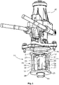
- figure 1 shows a perspective view of a flap device according to the invention.
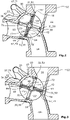
- figure 2 shows the flap device according to the invention in the axial direction of the shaft in a sectional representation in a first end position.
- figure 3 shows the flap device according to the invention in the axial direction of the shaft in a sectional view in a second end position.
- the flap device according to the invention consists of a flap housing 10, which is cylindrical in the present exemplary embodiment and is designed as a plug-in housing that can be pushed into a connection housing 12 in the axial direction.
- a central inlet duct 14 as well as a first outlet duct 16 and a second outlet duct 18 are formed on the connection housing 12, which, viewed from the inlet duct 14, are opposite to one another from a receiving opening 20 for the valve housing 10 and are offset on both sides in the direction of rotation by 90° to the inlet duct 14 extend into the continuing connection housing 12 .
- the flap housing 10 has an inlet 22 corresponding to the inlet duct 14 and into which the inlet duct 14 opens, as well as a first outlet 24 which opens into the first outlet duct 16 and a second outlet 26 which opens into the second outlet duct 18 .
- the flap housing 10 consists of a cover part 27 and a base 28, which are circular and between which four struts 30, 31, 32, 34 extend, which extend from the base 28 to the cover part 27. Webs 29 adjoin these struts 30, 31, 32, 34, which extend radially inward along the base 28 and the cover part 27.
- the stops 48, 50, 52, 54 each have a valve seat surface 56, 58, 60, 62, with the two valve seat surfaces 56, 58, 60, 62 pointing away from the outlets 24, 26, viewed in the circumferential direction, so that the respective acting valve seat surfaces 56, 58, 60, 62 are offset by 180 ° to each other and each valve seat surface 56, 58, 60, 62 to the next valve seat surface 58, 60, 62, 56 is arranged offset by 90 °.
- the flap body 44 is divided by the shaft 42 into two equal flap halves 64, 66, each flap half 64, 66 interacting with the two valve seat surfaces 56, 58, 60, 62, between which it is rotated by the flap halves 64, 66 with its Outer peripheral portion 67 perpendicular to the valve seat surfaces 56, 58, 60, 62 rest.
- the flap half 64, 66 also corresponds in shape to the valve seat surfaces 56, 58, 60, 62, the inner circumference of which is selected to be only slightly smaller than the outer circumference of the flap body 44. In the end positions, the flap body 44 extends parallel to the valve seat surfaces 56 , 58, 60, 62.
- the flap halves 64, 66 are approximately rectangular in shape with rounded corners and have a layered structure consisting of a first dimensionally stable flap plate 68 and a second dimensionally stable flap plate 70, between which there is a flexible sealing element designed as a spring steel plate 72 is arranged, which protrudes radially evenly over the peripheral edge of the flap plates 68, 70, so that two flexible U-shaped outer surfaces 74 delimit the flap body 44, which form the outer peripheral region 67 of the flap halves 64, 66.
- the two flap plates 68, 70 can be inserted with the interposition of the Sealing element 72 are connected to each other by screws or rivets or by welding.
- the two flexible U-shaped outer surfaces 74 rest perpendicularly on the valve seat surfaces 56, 58, 60, 62 in the end positions of the flap body 44.
- an exhaust gas flow can flow from the inlet duct 14 to the inlet 22 and past the flap body 44 to the first outlet duct 16, while the second outlet duct 18 is covered by the flap body 44, with a high degree of tightness being ensured by the surrounding and vertical contact of the two outer surfaces 74 of the flexible Sealing element 72 on the valve seat surfaces 56, 60 is achieved.
- the flap body 44 When the shaft 42 is actuated, the flap body 44 is turned counterclockwise away from the valve seat surfaces 56, 60 until, after about 90°, the opposite side of the outer surfaces 74 rests perpendicularly on the valve seat surfaces 58, 62, with the outer surface 74 of the first flap half 64 rests against the valve seat surface 58 at the third stop 50 and the outer surface 74 of the second flap half 66 rests against the valve seat surface 62 at the fourth stop 54 . Accordingly, in this second end position, the exhaust gas flow passes from the inlet port 14 via the inlet 22 of the flap device along the surface of the flap body 44 to the second outlet 26 and into the second outlet port 18.
- the invention is not limited to the exemplary embodiment described, but that various constructive changes are possible.
- the flap body and the valve seat surfaces can also be round or oval, in which case the shape of the struts and webs would have to be adapted to the shape of the flap in order to form a circumferential valve seat.
- An annular or U-shaped sealing element can also be clamped between the flap plates.
Claims (9)
- Dispositif de clapet pour un moteur à combustion interne comprenant un boîtier de clapet (10) dans lequel sont formées une entrée (22) et deux sorties (24, 26),et un corps de clapet (44) qui présente deux moitiés de clapet (64, 66) et qui est disposé sur un arbre (42) monté rotatif dans le boîtier de clapet (10) et duquel partent les deux moitiés de clapet (64, 66) des deux côtés, dans lequel une première butée (48) et une deuxième butée (52) sont formées dans le boîtier de clapet (10), contre chacune desquelles une moitié de clapet (64 ; 66) du corps de clapet (44) repose dans une première position d'extrémité du corps de clapet (44), et une troisième butée (50) et une quatrième butée (54) sont formées, contre chacune desquelles une demi clapet (64 ; 66) du corps de clapet (44) repose dans une deuxième position d'extrémité du corps de clapet (44), les moitiés de clapet (64, 66) reposant dans leurs deux positions d'extrémité respectivement avec toute leur zone périphérique extérieure (67) perpendiculairement sur des surfaces de siège de soupape (56, 58, 60, 62) qui sont formées sur les butées (48, 50, 52, 54), les moitiés de clapet (64, 66) s'étendant dans les positions d'extrémité essentiellement parallèlement aux surfaces de siège de soupape (56, 58, 60, 62)caractérisé en ce quele corps de clapet (44) présente une première plaque de clapet inflexible (68) et une deuxième plaque de clapet inflexible (70), entre lesquelles est serré un élément d'étanchéité flexible (72) qui fait saillie radialement sur la circonférence des deux plaques de clapet (68, 70), de sorte qu'une surface extérieure (74) de l'élément d'étanchéité (72) forme la région circonférentielle extérieure (67) du corps de clapet (44) qui, dans les deux positions d'extrémité, repose contre les surfaces de siège de soupape (56, 58, 60, 62) et en ce que le boîtier de clapet (10) est réalisé sous la forme d'un boîtier cylindrique enfichable qui, avec le corps de clapet (44) et l'arbre (42), est enfiché dans une ouverture de réception (20) d'un boîtier de raccordement (12) dans la direction axiale de l'arbre (42) et du boîtier cylindrique enfichable, de sorte qu'un canal d'entrée (14) du boîtier de raccordement (12) débouche dans l'entrée (22) du boîtier de clapet (10) et que deux canaux de sortie (16, 18) du boîtier de raccordement (12) partent des sorties (24, 26) du boîtier de clapet (10).
- Dispositif de clapet pour un moteur à combustion interne selon la revendication 1,
caractérisé en ce que
dans les positions d'extrémité, la zone périphérique extérieure (67) des demi-clapets (64, 66) formée par les surfaces extérieures (74) de l'élément d'étanchéité (72) dépassant radialement des plaques de clapet (68, 70) repose à plat sur la surface de siège de soupape (56, 58, 60, 62) respectivement associée, qui correspond à la zone périphérique extérieure (67) du corps de clapet (44). - Dispositif de clapet pour un moteur à combustion interne selon l'une des revendications 1 ou 2,
caractérisé en ce que
l'entrée (22) et les deux sorties (24, 26) sont formées de manière décalée l'une par rapport à l'autre dans le sens de rotation, l'entrée (22) étant disposée entre les deux sorties (24, 26). - Dispositif de clapet pour moteur à combustion interne selon l'une des revendications précédentes,
caractérisé en ce que
l'élément d'étanchéité souple (72) est une lamelle élastique. - Dispositif de clapet pour moteur à combustion interne selon l'une des revendications précédentes,
caractérisé en ce que
les deux clapets (68, 70) et l'élément d'étanchéité souple (72) sont fixés l'un à l'autre au moyen d'une liaison par vis. - Dispositif de clapet pour moteur à combustion interne selon l'une des revendications précédentes,
caractérisé en ce que
la première sortie (24) est disposée décalée de 90° par rapport à l'entrée (22) dans le sens de rotation, et l'entrée (22) est disposée décalée de 90° par rapport à la deuxième sortie (26). - Dispositif de clapet pour un moteur à combustion interne selon la revendication 6,
caractérisé en ce que
l'entrée (22) et les sorties (24, 26) s'étendent chacune sur des angles de rotation de 90° du corps de clapet (44). - Dispositif de clapet pour moteur à combustion interne selon l'une quelconque des revendications précédentes,
caractérisé en ce que
le corps de clapet (10) est conçu pour être fermé radialement à l'opposé de l'entrée (22). - Dispositif de clapet pour moteur à combustion interne selon l'une des revendications précédentes,
caractérisé en ce que
le carter de clapet (10) présente un fond (28) et une partie de couvercle (27) sur lesquels sont formées des nervures (29) qui, avec quatre entretoises (30, 31, 32, 34) reliant le fond (28) à la partie de couvercle (27), forment les butées (48, 50, 52, 54).
Applications Claiming Priority (1)
| Application Number | Priority Date | Filing Date | Title |
|---|---|---|---|
| DE102019105932.1A DE102019105932A1 (de) | 2019-03-08 | 2019-03-08 | Klappenvorrichtung für eine Verbrennungskraftmaschine |
Publications (2)
| Publication Number | Publication Date |
|---|---|
| EP3705696A1 EP3705696A1 (fr) | 2020-09-09 |
| EP3705696B1 true EP3705696B1 (fr) | 2022-05-04 |
Family
ID=69743113
Family Applications (1)
| Application Number | Title | Priority Date | Filing Date |
|---|---|---|---|
| EP20160373.5A Active EP3705696B1 (fr) | 2019-03-08 | 2020-03-02 | Dispositif à clapet pour un moteur à combustion interne |
Country Status (2)
| Country | Link |
|---|---|
| EP (1) | EP3705696B1 (fr) |
| DE (1) | DE102019105932A1 (fr) |
Families Citing this family (2)
| Publication number | Priority date | Publication date | Assignee | Title |
|---|---|---|---|---|
| CN112587016B (zh) * | 2020-11-19 | 2023-04-07 | 慈溪市万能电子有限公司 | 一种洗漱产品杀菌消毒器具 |
| CN113028097B (zh) * | 2021-02-25 | 2022-08-26 | 安徽同建建设集团有限公司 | 一种房屋建筑排水系统管道 |
Family Cites Families (10)
| Publication number | Priority date | Publication date | Assignee | Title |
|---|---|---|---|---|
| DE7716337U1 (de) * | 1977-05-24 | 1985-05-15 | Taake, Wilhelm, 4970 Bad Oeynhausen | Mischer mit Beipass |
| DE3700219A1 (de) * | 1987-01-07 | 1988-07-21 | Teves Gmbh Alfred | Elektromagnetisch betaetigbares 3/2-wegeventil |
| FR2790300B1 (fr) * | 1999-02-26 | 2001-04-27 | Mark Iv Systemes Moteurs Sa | Ensemble a clapet et dispositif de circulation et de distribution de fluide comprenant un tel ensemble |
| JP2002349720A (ja) * | 2001-05-31 | 2002-12-04 | Aisan Ind Co Ltd | バルブ装置 |
| JP2004239288A (ja) * | 2003-02-03 | 2004-08-26 | Aisan Ind Co Ltd | バルブ装置 |
| DE102005012842A1 (de) * | 2005-03-19 | 2006-09-21 | Daimlerchrysler Ag | Luftansaugvorrichtung für eine Brennkraftmaschine mit einsetzbarer Bypassklappeneinrichtung |
| DE102008048912B4 (de) * | 2008-09-26 | 2021-11-04 | Faurecia Emissions Control Technologies, Germany Gmbh | Abgasanlage und Abgasventil zur Steuerung eines Volumenstroms von Abgas sowie ein Verfahren zur Steuerung eines Volumenstroms |
| DE102011106744B3 (de) * | 2011-06-28 | 2012-12-27 | Pierburg Gmbh | Ventilvorrichtung zur Regelung eines Abgasstroms einer Verbrennungskraftmaschine |
| DE102013111215B4 (de) * | 2013-10-10 | 2019-11-07 | Pierburg Gmbh | Drosselklappenstutzen für eine Brennkraftmaschine sowie Verfahren zur Regelung einer Drosselklappe in einem Drosselklappenstutzen |
| WO2017174121A1 (fr) * | 2016-04-06 | 2017-10-12 | Pierburg Gmbh | Dispositif de vanne de gaz d'échappement |
-
2019
- 2019-03-08 DE DE102019105932.1A patent/DE102019105932A1/de active Pending
-
2020
- 2020-03-02 EP EP20160373.5A patent/EP3705696B1/fr active Active
Also Published As
| Publication number | Publication date |
|---|---|
| EP3705696A1 (fr) | 2020-09-09 |
| DE102019105932A1 (de) | 2020-09-10 |
Similar Documents
| Publication | Publication Date | Title |
|---|---|---|
| DE19500475C2 (de) | Absperr- oder Drosselventil mit drehbarer Ventilklappe | |
| EP1747369B1 (fr) | Dispositif soupape a deux voies reglable | |
| DE102012107908B4 (de) | Abgaswärmetauscher | |
| EP2728156B1 (fr) | Dispositif de réglage pour un moteur à combustion interne | |
| DE102011077766A1 (de) | Betätigungseinrichtung für ein Abgasstrom-Steuerelement eines Abgasturboladers | |
| DE202011109832U1 (de) | Betätigungseinrichtung für ein Abgasstrom-Steuerelement eines Abgasturboladers | |
| DE10321638A1 (de) | Schaltbarer Abgaswärmetauscher | |
| DE102016117801A1 (de) | Element einer Abgasleitung mit einem Ventil mit zusätzlichen Anschlägen | |
| EP3705696B1 (fr) | Dispositif à clapet pour un moteur à combustion interne | |
| DE102012106888A1 (de) | Abgasklappenanordnung mit integriertem Bypass | |
| EP2881634A1 (fr) | Système de clapet pour un actionneur, en particulier pour une soupape de gaz d'échappement d'un moteur à combustion interne | |
| EP2395216B1 (fr) | Dispositif de clapets pour un moteur à combustion interne | |
| DE102015122379A1 (de) | Ventilvorrichtung für eine Verbrennungskraftmaschine | |
| WO2017216241A1 (fr) | Système de clapet d'étranglement et procédé de fabrication d'un système de clapet d'étranglement | |
| DE102009012211A1 (de) | Klappenvorrichtung für eine Verbrennungskraftmaschine | |
| EP3551867B1 (fr) | Dispositif clapet | |
| EP3379070B1 (fr) | Dispositif de clapet de gaz d' échappement pour un moteur à combustion interne | |
| EP3807509B1 (fr) | Dispositif à volet pour un moteur à combustion interne | |
| DE102013107587A1 (de) | Ventil, insbesondere Abgasweiche für einen Verbrennungsmotor | |
| EP1462624A1 (fr) | Vanne d'air secondaire | |
| EP3628852B1 (fr) | Soupape et procédé de fabrication d'une soupape | |
| DE102008030785B4 (de) | Abgasrückführvorrichtung für eine Verbrennungskraftmaschine | |
| EP2130642A2 (fr) | Procédé de montage d'un clapet dans un boîtier | |
| DE102013106627B4 (de) | Klappenvorrichtung für eine Verbrennungskraftmaschine | |
| DE102015111252A1 (de) | Ventil für einen Abgasstrang einer Brennkraftmaschine |
Legal Events
| Date | Code | Title | Description |
|---|---|---|---|
| PUAI | Public reference made under article 153(3) epc to a published international application that has entered the european phase |
Free format text: ORIGINAL CODE: 0009012 |
|
| STAA | Information on the status of an ep patent application or granted ep patent |
Free format text: STATUS: THE APPLICATION HAS BEEN PUBLISHED |
|
| AK | Designated contracting states |
Kind code of ref document: A1 Designated state(s): AL AT BE BG CH CY CZ DE DK EE ES FI FR GB GR HR HU IE IS IT LI LT LU LV MC MK MT NL NO PL PT RO RS SE SI SK SM TR |
|
| AX | Request for extension of the european patent |
Extension state: BA ME |
|
| STAA | Information on the status of an ep patent application or granted ep patent |
Free format text: STATUS: REQUEST FOR EXAMINATION WAS MADE |
|
| 17P | Request for examination filed |
Effective date: 20210226 |
|
| RBV | Designated contracting states (corrected) |
Designated state(s): AL AT BE BG CH CY CZ DE DK EE ES FI FR GB GR HR HU IE IS IT LI LT LU LV MC MK MT NL NO PL PT RO RS SE SI SK SM TR |
|
| STAA | Information on the status of an ep patent application or granted ep patent |
Free format text: STATUS: EXAMINATION IS IN PROGRESS |
|
| 17Q | First examination report despatched |
Effective date: 20210429 |
|
| GRAP | Despatch of communication of intention to grant a patent |
Free format text: ORIGINAL CODE: EPIDOSNIGR1 |
|
| STAA | Information on the status of an ep patent application or granted ep patent |
Free format text: STATUS: GRANT OF PATENT IS INTENDED |
|
| GRAJ | Information related to disapproval of communication of intention to grant by the applicant or resumption of examination proceedings by the epo deleted |
Free format text: ORIGINAL CODE: EPIDOSDIGR1 |
|
| GRAP | Despatch of communication of intention to grant a patent |
Free format text: ORIGINAL CODE: EPIDOSNIGR1 |
|
| INTG | Intention to grant announced |
Effective date: 20211012 |
|
| INTG | Intention to grant announced |
Effective date: 20211026 |
|
| GRAS | Grant fee paid |
Free format text: ORIGINAL CODE: EPIDOSNIGR3 |
|
| GRAA | (expected) grant |
Free format text: ORIGINAL CODE: 0009210 |
|
| STAA | Information on the status of an ep patent application or granted ep patent |
Free format text: STATUS: THE PATENT HAS BEEN GRANTED |
|
| AK | Designated contracting states |
Kind code of ref document: B1 Designated state(s): AL AT BE BG CH CY CZ DE DK EE ES FI FR GB GR HR HU IE IS IT LI LT LU LV MC MK MT NL NO PL PT RO RS SE SI SK SM TR |
|
| REG | Reference to a national code |
Ref country code: GB Ref legal event code: FG4D Free format text: NOT ENGLISH |
|
| REG | Reference to a national code |
Ref country code: CH Ref legal event code: EP |
|
| REG | Reference to a national code |
Ref country code: AT Ref legal event code: REF Ref document number: 1489252 Country of ref document: AT Kind code of ref document: T Effective date: 20220515 |
|
| REG | Reference to a national code |
Ref country code: IE Ref legal event code: FG4D Free format text: LANGUAGE OF EP DOCUMENT: GERMAN Ref country code: DE Ref legal event code: R096 Ref document number: 502020001027 Country of ref document: DE |
|
| REG | Reference to a national code |
Ref country code: LT Ref legal event code: MG9D |
|
| REG | Reference to a national code |
Ref country code: NL Ref legal event code: MP Effective date: 20220504 |
|
| PG25 | Lapsed in a contracting state [announced via postgrant information from national office to epo] |
Ref country code: SE Free format text: LAPSE BECAUSE OF FAILURE TO SUBMIT A TRANSLATION OF THE DESCRIPTION OR TO PAY THE FEE WITHIN THE PRESCRIBED TIME-LIMIT Effective date: 20220504 Ref country code: PT Free format text: LAPSE BECAUSE OF FAILURE TO SUBMIT A TRANSLATION OF THE DESCRIPTION OR TO PAY THE FEE WITHIN THE PRESCRIBED TIME-LIMIT Effective date: 20220905 Ref country code: NO Free format text: LAPSE BECAUSE OF FAILURE TO SUBMIT A TRANSLATION OF THE DESCRIPTION OR TO PAY THE FEE WITHIN THE PRESCRIBED TIME-LIMIT Effective date: 20220804 Ref country code: NL Free format text: LAPSE BECAUSE OF FAILURE TO SUBMIT A TRANSLATION OF THE DESCRIPTION OR TO PAY THE FEE WITHIN THE PRESCRIBED TIME-LIMIT Effective date: 20220504 Ref country code: LT Free format text: LAPSE BECAUSE OF FAILURE TO SUBMIT A TRANSLATION OF THE DESCRIPTION OR TO PAY THE FEE WITHIN THE PRESCRIBED TIME-LIMIT Effective date: 20220504 Ref country code: HR Free format text: LAPSE BECAUSE OF FAILURE TO SUBMIT A TRANSLATION OF THE DESCRIPTION OR TO PAY THE FEE WITHIN THE PRESCRIBED TIME-LIMIT Effective date: 20220504 Ref country code: GR Free format text: LAPSE BECAUSE OF FAILURE TO SUBMIT A TRANSLATION OF THE DESCRIPTION OR TO PAY THE FEE WITHIN THE PRESCRIBED TIME-LIMIT Effective date: 20220805 Ref country code: FI Free format text: LAPSE BECAUSE OF FAILURE TO SUBMIT A TRANSLATION OF THE DESCRIPTION OR TO PAY THE FEE WITHIN THE PRESCRIBED TIME-LIMIT Effective date: 20220504 Ref country code: ES Free format text: LAPSE BECAUSE OF FAILURE TO SUBMIT A TRANSLATION OF THE DESCRIPTION OR TO PAY THE FEE WITHIN THE PRESCRIBED TIME-LIMIT Effective date: 20220504 Ref country code: BG Free format text: LAPSE BECAUSE OF FAILURE TO SUBMIT A TRANSLATION OF THE DESCRIPTION OR TO PAY THE FEE WITHIN THE PRESCRIBED TIME-LIMIT Effective date: 20220804 |
|
| PG25 | Lapsed in a contracting state [announced via postgrant information from national office to epo] |
Ref country code: RS Free format text: LAPSE BECAUSE OF FAILURE TO SUBMIT A TRANSLATION OF THE DESCRIPTION OR TO PAY THE FEE WITHIN THE PRESCRIBED TIME-LIMIT Effective date: 20220504 Ref country code: PL Free format text: LAPSE BECAUSE OF FAILURE TO SUBMIT A TRANSLATION OF THE DESCRIPTION OR TO PAY THE FEE WITHIN THE PRESCRIBED TIME-LIMIT Effective date: 20220504 Ref country code: LV Free format text: LAPSE BECAUSE OF FAILURE TO SUBMIT A TRANSLATION OF THE DESCRIPTION OR TO PAY THE FEE WITHIN THE PRESCRIBED TIME-LIMIT Effective date: 20220504 Ref country code: IS Free format text: LAPSE BECAUSE OF FAILURE TO SUBMIT A TRANSLATION OF THE DESCRIPTION OR TO PAY THE FEE WITHIN THE PRESCRIBED TIME-LIMIT Effective date: 20220904 |
|
| PG25 | Lapsed in a contracting state [announced via postgrant information from national office to epo] |
Ref country code: SM Free format text: LAPSE BECAUSE OF FAILURE TO SUBMIT A TRANSLATION OF THE DESCRIPTION OR TO PAY THE FEE WITHIN THE PRESCRIBED TIME-LIMIT Effective date: 20220504 Ref country code: SK Free format text: LAPSE BECAUSE OF FAILURE TO SUBMIT A TRANSLATION OF THE DESCRIPTION OR TO PAY THE FEE WITHIN THE PRESCRIBED TIME-LIMIT Effective date: 20220504 Ref country code: RO Free format text: LAPSE BECAUSE OF FAILURE TO SUBMIT A TRANSLATION OF THE DESCRIPTION OR TO PAY THE FEE WITHIN THE PRESCRIBED TIME-LIMIT Effective date: 20220504 Ref country code: EE Free format text: LAPSE BECAUSE OF FAILURE TO SUBMIT A TRANSLATION OF THE DESCRIPTION OR TO PAY THE FEE WITHIN THE PRESCRIBED TIME-LIMIT Effective date: 20220504 Ref country code: DK Free format text: LAPSE BECAUSE OF FAILURE TO SUBMIT A TRANSLATION OF THE DESCRIPTION OR TO PAY THE FEE WITHIN THE PRESCRIBED TIME-LIMIT Effective date: 20220504 Ref country code: CZ Free format text: LAPSE BECAUSE OF FAILURE TO SUBMIT A TRANSLATION OF THE DESCRIPTION OR TO PAY THE FEE WITHIN THE PRESCRIBED TIME-LIMIT Effective date: 20220504 |
|
| REG | Reference to a national code |
Ref country code: DE Ref legal event code: R097 Ref document number: 502020001027 Country of ref document: DE |
|
| PLBE | No opposition filed within time limit |
Free format text: ORIGINAL CODE: 0009261 |
|
| STAA | Information on the status of an ep patent application or granted ep patent |
Free format text: STATUS: NO OPPOSITION FILED WITHIN TIME LIMIT |
|
| PG25 | Lapsed in a contracting state [announced via postgrant information from national office to epo] |
Ref country code: AL Free format text: LAPSE BECAUSE OF FAILURE TO SUBMIT A TRANSLATION OF THE DESCRIPTION OR TO PAY THE FEE WITHIN THE PRESCRIBED TIME-LIMIT Effective date: 20220504 |
|
| 26N | No opposition filed |
Effective date: 20230207 |
|
| PG25 | Lapsed in a contracting state [announced via postgrant information from national office to epo] |
Ref country code: SI Free format text: LAPSE BECAUSE OF FAILURE TO SUBMIT A TRANSLATION OF THE DESCRIPTION OR TO PAY THE FEE WITHIN THE PRESCRIBED TIME-LIMIT Effective date: 20220504 |
|
| PGFP | Annual fee paid to national office [announced via postgrant information from national office to epo] |
Ref country code: DE Payment date: 20230320 Year of fee payment: 4 |
|
| PG25 | Lapsed in a contracting state [announced via postgrant information from national office to epo] |
Ref country code: MC Free format text: LAPSE BECAUSE OF FAILURE TO SUBMIT A TRANSLATION OF THE DESCRIPTION OR TO PAY THE FEE WITHIN THE PRESCRIBED TIME-LIMIT Effective date: 20220504 |
|
| REG | Reference to a national code |
Ref country code: CH Ref legal event code: PL |
|
| REG | Reference to a national code |
Ref country code: BE Ref legal event code: MM Effective date: 20230331 |
|
| PG25 | Lapsed in a contracting state [announced via postgrant information from national office to epo] |
Ref country code: LU Free format text: LAPSE BECAUSE OF NON-PAYMENT OF DUE FEES Effective date: 20230302 |
|
| REG | Reference to a national code |
Ref country code: IE Ref legal event code: MM4A |
|
| PG25 | Lapsed in a contracting state [announced via postgrant information from national office to epo] |
Ref country code: LI Free format text: LAPSE BECAUSE OF NON-PAYMENT OF DUE FEES Effective date: 20230331 Ref country code: IT Free format text: LAPSE BECAUSE OF FAILURE TO SUBMIT A TRANSLATION OF THE DESCRIPTION OR TO PAY THE FEE WITHIN THE PRESCRIBED TIME-LIMIT Effective date: 20220504 Ref country code: IE Free format text: LAPSE BECAUSE OF NON-PAYMENT OF DUE FEES Effective date: 20230302 Ref country code: FR Free format text: LAPSE BECAUSE OF NON-PAYMENT OF DUE FEES Effective date: 20230331 Ref country code: CH Free format text: LAPSE BECAUSE OF NON-PAYMENT OF DUE FEES Effective date: 20230331 |
|
| PG25 | Lapsed in a contracting state [announced via postgrant information from national office to epo] |
Ref country code: BE Free format text: LAPSE BECAUSE OF NON-PAYMENT OF DUE FEES Effective date: 20230331 |
|
| PGFP | Annual fee paid to national office [announced via postgrant information from national office to epo] |
Ref country code: DE Payment date: 20240321 Year of fee payment: 5 |