EP3551867B1 - Dispositif clapet - Google Patents
Dispositif clapet Download PDFInfo
- Publication number
- EP3551867B1 EP3551867B1 EP17811264.5A EP17811264A EP3551867B1 EP 3551867 B1 EP3551867 B1 EP 3551867B1 EP 17811264 A EP17811264 A EP 17811264A EP 3551867 B1 EP3551867 B1 EP 3551867B1
- Authority
- EP
- European Patent Office
- Prior art keywords
- flap
- flow channel
- opening
- cover
- limiter
- Prior art date
- Legal status (The legal status is an assumption and is not a legal conclusion. Google has not performed a legal analysis and makes no representation as to the accuracy of the status listed.)
- Active
Links
Images
Classifications
-
- F—MECHANICAL ENGINEERING; LIGHTING; HEATING; WEAPONS; BLASTING
- F02—COMBUSTION ENGINES; HOT-GAS OR COMBUSTION-PRODUCT ENGINE PLANTS
- F02D—CONTROLLING COMBUSTION ENGINES
- F02D9/00—Controlling engines by throttling air or fuel-and-air induction conduits or exhaust conduits
- F02D9/08—Throttle valves specially adapted therefor; Arrangements of such valves in conduits
- F02D9/10—Throttle valves specially adapted therefor; Arrangements of such valves in conduits having pivotally-mounted flaps
- F02D9/1065—Mechanical control linkage between an actuator and the flap, e.g. including levers, gears, springs, clutches, limit stops of the like
-
- F—MECHANICAL ENGINEERING; LIGHTING; HEATING; WEAPONS; BLASTING
- F02—COMBUSTION ENGINES; HOT-GAS OR COMBUSTION-PRODUCT ENGINE PLANTS
- F02D—CONTROLLING COMBUSTION ENGINES
- F02D9/00—Controlling engines by throttling air or fuel-and-air induction conduits or exhaust conduits
- F02D9/08—Throttle valves specially adapted therefor; Arrangements of such valves in conduits
- F02D9/10—Throttle valves specially adapted therefor; Arrangements of such valves in conduits having pivotally-mounted flaps
- F02D9/1035—Details of the valve housing
-
- F—MECHANICAL ENGINEERING; LIGHTING; HEATING; WEAPONS; BLASTING
- F02—COMBUSTION ENGINES; HOT-GAS OR COMBUSTION-PRODUCT ENGINE PLANTS
- F02M—SUPPLYING COMBUSTION ENGINES IN GENERAL WITH COMBUSTIBLE MIXTURES OR CONSTITUENTS THEREOF
- F02M26/00—Engine-pertinent apparatus for adding exhaust gases to combustion-air, main fuel or fuel-air mixture, e.g. by exhaust gas recirculation [EGR] systems
- F02M26/65—Constructional details of EGR valves
- F02M26/70—Flap valves; Rotary valves; Sliding valves; Resilient valves
-
- F—MECHANICAL ENGINEERING; LIGHTING; HEATING; WEAPONS; BLASTING
- F16—ENGINEERING ELEMENTS AND UNITS; GENERAL MEASURES FOR PRODUCING AND MAINTAINING EFFECTIVE FUNCTIONING OF MACHINES OR INSTALLATIONS; THERMAL INSULATION IN GENERAL
- F16K—VALVES; TAPS; COCKS; ACTUATING-FLOATS; DEVICES FOR VENTING OR AERATING
- F16K1/00—Lift valves or globe valves, i.e. cut-off apparatus with closure members having at least a component of their opening and closing motion perpendicular to the closing faces
- F16K1/16—Lift valves or globe valves, i.e. cut-off apparatus with closure members having at least a component of their opening and closing motion perpendicular to the closing faces with pivoted closure-members
- F16K1/18—Lift valves or globe valves, i.e. cut-off apparatus with closure members having at least a component of their opening and closing motion perpendicular to the closing faces with pivoted closure-members with pivoted discs or flaps
- F16K1/22—Lift valves or globe valves, i.e. cut-off apparatus with closure members having at least a component of their opening and closing motion perpendicular to the closing faces with pivoted closure-members with pivoted discs or flaps with axis of rotation crossing the valve member, e.g. butterfly valves
- F16K1/221—Lift valves or globe valves, i.e. cut-off apparatus with closure members having at least a component of their opening and closing motion perpendicular to the closing faces with pivoted closure-members with pivoted discs or flaps with axis of rotation crossing the valve member, e.g. butterfly valves specially adapted operating means therefor
-
- F—MECHANICAL ENGINEERING; LIGHTING; HEATING; WEAPONS; BLASTING
- F16—ENGINEERING ELEMENTS AND UNITS; GENERAL MEASURES FOR PRODUCING AND MAINTAINING EFFECTIVE FUNCTIONING OF MACHINES OR INSTALLATIONS; THERMAL INSULATION IN GENERAL
- F16K—VALVES; TAPS; COCKS; ACTUATING-FLOATS; DEVICES FOR VENTING OR AERATING
- F16K1/00—Lift valves or globe valves, i.e. cut-off apparatus with closure members having at least a component of their opening and closing motion perpendicular to the closing faces
- F16K1/32—Details
- F16K1/52—Means for additional adjustment of the rate of flow
- F16K1/523—Means for additional adjustment of the rate of flow for limiting the maximum flow rate, using a stop
-
- F—MECHANICAL ENGINEERING; LIGHTING; HEATING; WEAPONS; BLASTING
- F16—ENGINEERING ELEMENTS AND UNITS; GENERAL MEASURES FOR PRODUCING AND MAINTAINING EFFECTIVE FUNCTIONING OF MACHINES OR INSTALLATIONS; THERMAL INSULATION IN GENERAL
- F16K—VALVES; TAPS; COCKS; ACTUATING-FLOATS; DEVICES FOR VENTING OR AERATING
- F16K11/00—Multiple-way valves, e.g. mixing valves; Pipe fittings incorporating such valves
- F16K11/02—Multiple-way valves, e.g. mixing valves; Pipe fittings incorporating such valves with all movable sealing faces moving as one unit
- F16K11/04—Multiple-way valves, e.g. mixing valves; Pipe fittings incorporating such valves with all movable sealing faces moving as one unit comprising only lift valves
- F16K11/052—Multiple-way valves, e.g. mixing valves; Pipe fittings incorporating such valves with all movable sealing faces moving as one unit comprising only lift valves with pivoted closure members, e.g. butterfly valves
- F16K11/0525—Multiple-way valves, e.g. mixing valves; Pipe fittings incorporating such valves with all movable sealing faces moving as one unit comprising only lift valves with pivoted closure members, e.g. butterfly valves the closure members being pivoted around an essentially central axis
-
- F—MECHANICAL ENGINEERING; LIGHTING; HEATING; WEAPONS; BLASTING
- F02—COMBUSTION ENGINES; HOT-GAS OR COMBUSTION-PRODUCT ENGINE PLANTS
- F02D—CONTROLLING COMBUSTION ENGINES
- F02D9/00—Controlling engines by throttling air or fuel-and-air induction conduits or exhaust conduits
- F02D9/02—Controlling engines by throttling air or fuel-and-air induction conduits or exhaust conduits concerning induction conduits
- F02D2009/0201—Arrangements; Control features; Details thereof
- F02D2009/0296—Throttle control device with stops for limiting throttle opening or closing beyond a certain position during certain periods of operation
-
- F—MECHANICAL ENGINEERING; LIGHTING; HEATING; WEAPONS; BLASTING
- F02—COMBUSTION ENGINES; HOT-GAS OR COMBUSTION-PRODUCT ENGINE PLANTS
- F02M—SUPPLYING COMBUSTION ENGINES IN GENERAL WITH COMBUSTIBLE MIXTURES OR CONSTITUENTS THEREOF
- F02M26/00—Engine-pertinent apparatus for adding exhaust gases to combustion-air, main fuel or fuel-air mixture, e.g. by exhaust gas recirculation [EGR] systems
- F02M26/65—Constructional details of EGR valves
- F02M26/71—Multi-way valves
Definitions
- the invention relates to a flap device for an internal combustion engine, with a flow duct housing, which delimits a flow duct with at least one inlet opening and a first outlet opening, a flap module, which can be inserted through an opening into the flow duct housing, and at least one flap shaft rotatably mounted in the flow duct housing, a the flap body arranged on the flap shaft for regulating a flow cross section of the flow channel, a bearing element arranged in the opening, through which the flap shaft extends, and an adjusting lever, which is non-rotatably connected to the flap shaft at one end of the flap shaft projecting out of the flow channel housing, and a coupling member for coupling having an actuating drive device and/or an actuating gear.
- flap devices are generally known and are used, for example, to regulate exhaust gas recirculation in a motor vehicle internal combustion engine in order to reduce the emission of pollutants. Due to the constantly increasing reduction in pollutant emissions, the requirements regarding the functions, the response behavior and the tightness of these flaps when closed are also increasing.
- a large number of flap devices are known in which a flap position or rotational freedom of movement of the flap shaft takes place by means of a mechanical stop device arranged outside the flow channel, on an actuating drive device and/or on an actuating gear.
- anchor devices are - depending on the design - in the structure and interaction of individual limiting components designed relatively expensive and complex, so that for the arrangement of such a stop device, a relatively large mounting space is required on the outside of the flow channel housing.
- the production, assembly and adjustment of such a flap device is relatively expensive.
- a flap device with a flap module that can be inserted into a flow channel housing is known.
- the flap shaft is adjusted and moved to a possible end position via a drive unit or a coupling linkage coupled to the flap module, with no stop device being provided.
- a flap device with a flap housing comprising a flap part, a drive device and a transmission gear is known.
- a position of a flap body that closes the channel is defined by an end stop of one of the gear wheels arranged on the flap housing.
- a flap device in which several flap modules are inserted into insertion openings of the intake manifold.
- the plugs that close the openings are attached to the intake manifold.
- Levers are attached to the shaft ends of the flaps, the outer edges of which can be rotated against stops on the plug in order to limit the movement.
- the invention is therefore based on the object of providing a flap device that enables a particularly precise control of an exhaust gas mass flow in all operating states, in particular even with small exhaust gas flows, in particular a high Tightness of the flap, the most compact design possible and the most cost-effective production and assembly is to be achieved.
- At least one limiter for limiting a rotational movement of the control lever is arranged on the adjusting lever and a separate cover closing the opening is arranged on the flow channel housing, on which at least one stop element functionally interacting with the limiter is arranged, the limiter being arranged as a limiter in the axial direction of the flap shaft Projection is formed and a recess is formed on the cover, which is delimited by a peripheral wall, which serves as a stop element for a limiter projecting into the recess.
- the actuating lever with the limiter can bear against the counter-limiter of the cover in at least one setting position, for example in a setting position which completely closes the flow channel.
- the setting position can be set or adjusted from the outside in a particularly simple manner, so that a particularly high degree of tightness of the flap is made possible.
- the relatively flat structure of the cover which can be fastened to the flow channel housing for example by a clip, a screw connection or another type of fastening, enables a particularly space-saving design of a stop element on the outside of the flow channel housing.
- the projection or projections can be arranged in such a way that when the actuating lever is rotated in at least one actuating position, the projections limit the rotational movement of the adjusting lever collide and further rotation is blocked.
- the projections advantageously each have a surface aligned with one another, with which the projections can lie against one another.
- a projection can be designed as a tab, a pin or a bent section of the actuating lever or the cover.
- the recess can be, for example, an opening, bore or groove formed on the cover, in whose plane of extension the adjusting lever with the limiter—for example formed as a projection—protrudes.
- the peripheral wall of the cover facing the recess can thus serve as a lateral delimitation or stop element for the delimiter that can be moved in the plane of the recess. This enables a particularly flat, space-saving and cost-effective design.
- the bearing element is arranged in the opening of the flow channel housing and forms a closure of the flow channel from the environment.
- a first stop element is arranged on a first peripheral wall section and a second stop element is arranged on a second peripheral wall section, wherein when the limiter rests against the first peripheral wall section, in particular in a first end setting position of the actuating lever, the flap body completely releases the first outlet opening in relation to the inlet opening and when the limiter is in contact with the second peripheral wall section, in particular in a second end setting position of the setting lever, the flap body completely closes the first outlet opening in relation to the inlet opening.
- the adjusting lever can thus be freely movable in a region between the two peripheral wall sections, in particular in the region of the recess, and its freedom of movement can be limited by the peripheral wall sections. This enables a particularly flat and space-saving design of a limiting device.
- the stop elements can be arranged at an angle of approximately 90° to one another with respect to a longitudinal axis of the flap shaft, in particular an axis of rotation of the flap shaft, so that the actuating lever can be rotated through an angle of rotation of approximately 90°.
- This enables optimal freedom of movement of the adjusting lever for completely opening and closing the flow channel by means of the flap body.
- the flow channel can be fully released in a first end setting position of the setting lever and completely closed in a second end setting position in which the setting lever is arranged rotated by 90° with respect to the first end setting position.
- the projection surface of the actuating lever and the flap shaft on the cover is preferably smaller than the recess in the cover. Consequently, the recess can be of such a large surface area that the actuating lever can penetrate the recess without contact at least in one actuating position of the actuating lever in the axial direction of the flap shaft.
- the flap module including the adjusting lever, can first be inserted into the flow channel housing and then - when the cover is put on - the adjusting lever can be guided through the cover cutout and the cover placed on the flow housing and fastened to it, so that the cover is between Lever and flow channel housing is arranged. This enables a particularly flat, space-saving design that is cost-effective to manufacture and assemble.
- the cover has a fixing device for fixing the actuating drive device and/or the actuating gear.
- the fixing device can be designed, for example, as a protruding receiving section, into which a corresponding counter-section of an actuating drive device and/or an actuating gear can engage and can thus be held on the cover.
- the arrangement of an example on Flow channel housing separately arranged holder can be avoided. Consequently, a particularly space-saving and cost-effective design of a limiting device is made possible.
- a seal is preferably arranged between the cover and the flow channel housing.
- the flow channel housing can be sealed off from the environment primarily or additionally via a seal arranged on the cover.
- the seal can already be fastened or attached to the cover before final assembly, so that assembly can take place in a relatively simple manner.
- the coupling member is preferably designed as a ball coupling which preferably protrudes from the adjusting lever in the direction away from the flow channel housing.
- the coupling member and the limiter are preferably arranged opposite one another on the adjusting lever, in particular with regard to the longitudinal extension of the adjusting lever.
- the flap shaft is preferably mounted at a second free end, for example via a bushing, in a wall of the flow channel housing.
- the flap shaft can be mounted particularly precisely in the flow channel housing and a particularly high level of sealing of the flap can be achieved.
- the flow channel also has a second outlet opening, the flap body releasing a fluid flow between the inlet opening and the first outlet opening in a first position and blocking it between the inlet opening and the second outlet opening, and the flap body in a second position Fluid flow between the inlet port and the second outlet port releases and blocks between the inlet port and the first outlet port.
- both outlet openings can be released fluidically in relation to the inlet opening.
- the flap device can be used not only to regulate a flow but also to regulate a plurality of outlet openings, in particular as a valve.
- the flap device is particularly suitable for exhaust gas flap valves with a bypass channel.
- the flap body is preferably designed as a bent sheet metal and is placed radially on the flap shaft and fastened thereto.
- the flap body can be placed laterally on the shaft.
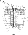
- the flap device 1 is designed as an exhaust gas recirculation valve and is used to regulate an exhaust gas flow in a flow channel 20, in particular an intake tract of a motor vehicle internal combustion engine, not shown.
- the flap device 1 has a flap module 3 which is inserted into a flow duct housing 2 delimiting the flow duct 20 .
- the flap module 3 comprises a flap shaft 30, a flap body 31 which is non-rotatably connected to the flap shaft 30, a bearing element 36 guiding the flap shaft 30 and an adjusting lever 33 for the rotary adjustment of the flap shaft 30 and the flap body 31.
- the flap module 3 forms a unit and can therefore completely pre-assembled into an opening 24 formed in the flow channel housing 2 for receiving the flap module 3 .
- the opening 24 of the flow channel housing 2 is advantageously designed to correspond to the flap module 3 , in the present case as a round recess arranged radially to the flow channel 20 .
- the flap shaft 30 has a first free end 37a which is arranged outside of the flow channel housing 2 and to which the adjusting lever 33 is attached.
- the flap shaft 30 extends through the bearing element 36 and transversely through the flow channel 20.
- the flap shaft 30 engages in a bushing 38 arranged on the flow channel housing 2 and is also mounted here.
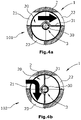
- the flap body 31 is present - as in particular in the Figures 4a and 4b is recognizable - placed radially on the flap shaft 30 as a bent rectangular sheet metal and attached thereto, in particular symmetrically to the flap shaft 30 .
- the gas pressure on the flap shaft 30 is distributed uniformly on both sides of the flap shaft 30 Flap body 31, so that to rotate the flap body 31, a relatively small actuating force is sufficient.
- the bearing element 36 is arranged in the area of the opening 24 of the flow channel housing 2 and forms a closure of the flow channel 20 with respect to the environment.
- the bearing element 36 has a sealing ring 36b on a radial inner side facing the flap shaft 30 .
- a circumferential sealing element 36a is arranged on an outside facing the flow channel housing 2 .
- the sealing elements 36a, 36b can each be designed as a lip sealing ring.
- the adjusting lever 33 for actuating the flap body 31 is arranged on the free end 37a of the flap shaft 30 protruding from the flow channel housing 2 and is connected to the flap shaft 30 in a rotationally fixed manner.
- the adjusting lever 33 has a coupling member 34 at a first end for coupling to an adjusting drive device 5 and/or an adjusting gear 51 .
- the adjusting lever 33 has a limiter 35 for limiting a rotary movement of the adjusting lever 33 .
- the limiter 35 is designed as a projection which is arranged in the axial direction of the flap shaft 30 and protrudes from the actuating lever 33 in the direction of the flow channel housing 2 .
- the limiter 35 is designed as a bent section of the adjusting lever 33 .
- a cover 4 is provided in order to secure the flap module 3 against falling out after the flap module 3 has been inserted into the opening 24 of the flow channel housing 2 .
- the cover 4 can be designed as a stamped and bent part and is attached to the outside of the flow channel housing 2 . In the present case, the cover 4 is fastened to the flow channel housing 2 via three screws 40 .
- a sealing element 44 is optionally provided between the cover 4 and the flow channel housing 2 .
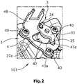
- the cover 4 has a fixing device 48, as in particular in FIG figure 2 is recognizable.
- the cover 4 has a central recess 41 through which the adjusting lever 33 can extend.
- the projected area of the actuating lever 33 and the flap shaft 30 is smaller than the recess 41.
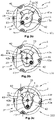
- the actuating lever 33 can be guided through the recess 41 of the cover 4 without touching it. This is advantageously done in the in Figure 3c shown third position 103 of the flap shaft 31.
- the limiter 35 arranged on the adjusting lever 33 is in the plane of the recess 41 of the cover 4, as in particular in figure 1 is recognizable.
- the freedom of movement of the limiter 35 can consequently be limited by a peripheral wall 42 surrounding the recess 41 .
- at least two peripheral wall sections 42a, 42b are formed on the peripheral wall 42 as stop elements 43a, 43b.
- a first stop element 43 is provided on a first peripheral wall section 42a
- a second stop element 43b is provided on a second peripheral wall section 42b
- the limiter 35 interacting with the first stop element 43a when the adjusting lever 33 is rotated in one direction and when the adjusting lever 33 is rotated in the other direction Direction can come into contact with the second stop element 43b.
- the limiter 35 can rest against the first stop element 43 in a first end setting position 101 and against the second stop element 43b in a second end setting position 102, as in particular in FIG Figures 3a and 3b shown.
- the flap body 31 arranged in the flow channel 20 can completely release a first outlet opening 22 in relation to an inlet opening 21, in which in Figure 3b shown second position 102 can of Flap body 31 completely close the first outlet opening 22 with respect to the inlet opening 21 .
- the flow channel housing 2 has an additional second outlet opening 23 in addition to the inlet opening 21 and the first outlet opening 22 .
- the first outlet opening 22 can be connected to a heat exchanger, not shown, and the second outlet opening 23 can be connected to a bypass line, not shown.
- the flap device 1 is provided for directing an exhaust gas flow from the inlet opening 21 to the first outlet opening 22 or to the second outlet opening 23, with a design change of the flap module 3 shown in the previous figures not being necessary.
- the flap body 31 completely uncovers the first outlet opening 22 in relation to the inlet opening 21 and closes the second outlet opening 23 in relation to the inlet opening 21.
- the flap body opens the second outlet opening 23 in relation to the inlet opening 21 and closes the first outlet opening 22 in relation to the inlet opening 21.
- the flap device 1 can in particular also serve as a 3/2-way valve.
Landscapes
- Engineering & Computer Science (AREA)
- General Engineering & Computer Science (AREA)
- Mechanical Engineering (AREA)
- Chemical & Material Sciences (AREA)
- Combustion & Propulsion (AREA)
- Physics & Mathematics (AREA)
- Fluid Mechanics (AREA)
- Lift Valve (AREA)
- Mechanically-Actuated Valves (AREA)
Claims (11)
- Dispositif de clapet (1) pour un moteur à combustion interne, avec- un boîtier de canal d'écoulement (2) qui délimite un canal d'écoulement (20) avec au moins une ouverture d'entrée (21) et une première ouverture de sortie (22),- un module de clapet (3) qui peut être inséré dans le boîtier de canal d'écoulement (2) à travers une ouverture (24) et au moins- un arbre de clapet (30) supporté de manière rotative dans le boîtier de canal d'écoulement (2),- un corps de clapet (31) disposé sur l'arbre de clapet (30) pour réguler une section transversale d'écoulement du canal d'écoulement (20),- un élément de palier (36) disposé dans l'ouverture (24), à travers lequel s'étend l'arbre de clapet (30), et- un levier de réglage (33) qui est relié de manière solidaire en rotation à l'arbre de clapet (30) à une extrémité (37a) de l'arbre de clapet (30) dépassant du boîtier de canal d'écoulement (2) et qui comprend un élément d'accouplement (34) pour l'accouplement avec un dispositif d'entraînement de réglage (5) et/ou un engrenage de réglage (51),caractérisé en ce que
au moins un limiteur (35) est disposé sur le levier de réglage (33) pour limiter un mouvement de rotation du levier de réglage (33), et un couvercle séparé (4) qui ferme l'ouverture (24) est disposé sur le boîtier de canal d'écoulement (2), sur lequel est disposé au moins un élément de butée (43a, 43b) qui coopère de manière fonctionnelle avec le limiteur (35), le limiteur (35) est réalisé sous la forme d'une saillie disposée dans la direction axiale de l'arbre de clapet (30) et un évidement (41) est réalisé sur le couvercle (4), lequel est délimité par une paroi périphérique (42, 42a, 42b) qui sert d'élément de butée (43a, 43b) pour un limiteur (35) qui fait saillie dans l'évidement (41), l'élément de palier (36) est disposé dans l'ouverture (24) du boîtier du canal d'écoulement (2) et constitue une fermeture du canal d'écoulement (20) par rapport à l'environnement. - Dispositif de clapet (1) selon la revendication 1, caractérisé en ce que
un premier élément de butée (43a) est formé par une première portion de paroi périphérique (42a) et un deuxième élément de butée (43b) est formé par une deuxième portion de paroi périphérique (42b), dans lequel, lorsque le limiteur (35) est en contact avec la première section de paroi périphérique (42a), le corps de clapet (31) libère complètement la première ouverture de sortie (22) par rapport à l'ouverture d'entrée (21) et, lorsque le limiteur (35) est en contact avec la deuxième section de paroi périphérique (42b), le corps de clapet (31) ferme complètement la première ouverture de sortie (22) par rapport à l'ouverture d'entrée (21). - Dispositif de clapet (1) selon la revendication 2, caractérisé en ce que
les éléments de butée (43a, 43b) sont disposés à un angle d'environ 90° l'un par rapport à l'autre par rapport à l'axe de rotation (A1) de l'arbre de clapet (30). - Dispositif de clapet (1) selon l'une des revendications précédentes, caractérisé en ce que
dans au moins une position de réglage (100) du levier de réglage (33), la surface de projection du levier de réglage (33) et de l'arbre de volet (30) sur le couvercle (4) est plus petite que l'évidement (41) dans le couvercle (4). - Dispositif de clapet (1) selon l'une des revendications précédentes, caractérisé en ce que
le couvercle (4) comprend un dispositif de fixation (48) pour fixer le dispositif d'actionnement (5) et/ou l'engrenage de réglage (51). - Dispositif de clapet (1) selon l'une des revendications précédentes, caractérisé en ce que
un joint d'étanchéité (44) est disposé entre le couvercle (4) et le boîtier du canal d'écoulement (2). - Dispositif de clapet (1) selon l'une des revendications précédentes, caractérisé en ce que
l'élément d'accouplement (34) est conçu comme un accouplement à billes. - Dispositif de clapet (1) selon l'une des revendications précédentes, caractérisé en ce que
l'élément d'accouplement (34) et le limiteur (35) sont disposés de manière opposée sur le levier de commande (33). - Dispositif de clapet (1) selon l'une des revendications précédentes, caractérisé en ce que
l'arbre de clapet (30) est supporté à une deuxième extrémité libre (37b) dans une paroi (25) du boîtier de canal d'écoulement (2). - Dispositif de clapet (1) selon l'une des revendications précédentes, caractérisé en ce que
le canal d'écoulement (20) comprend en plus un deuxième orifice de sortie (23), et le corps de clapet (31), dans une première position (101), libère un écoulement de fluide entre l'orifice d'entrée (21) et le premier orifice de sortie (22) et bloque entre l'orifice d'entrée (21) et le deuxième orifice de sortie (23), et dans une seconde position (102), il libère un écoulement de fluide entre l'ouverture d'entrée (21) et la seconde ouverture de sortie (23) et le bloque entre l'ouverture d'entrée (21) et la première ouverture de sortie (22). - Dispositif de clapet (1) selon l'une des revendications précédentes, caractérisé en ce que
le corps de clapet (31) est formé comme une tôle pliée et est placé et fixé radialement sur l'arbre de clapet (30).
Applications Claiming Priority (2)
| Application Number | Priority Date | Filing Date | Title |
|---|---|---|---|
| DE102016123738.8A DE102016123738B4 (de) | 2016-12-08 | 2016-12-08 | Klappenvorrichtung |
| PCT/EP2017/081201 WO2018104173A1 (fr) | 2016-12-08 | 2017-12-01 | Dispositif clapet |
Publications (2)
| Publication Number | Publication Date |
|---|---|
| EP3551867A1 EP3551867A1 (fr) | 2019-10-16 |
| EP3551867B1 true EP3551867B1 (fr) | 2023-01-25 |
Family
ID=60627611
Family Applications (1)
| Application Number | Title | Priority Date | Filing Date |
|---|---|---|---|
| EP17811264.5A Active EP3551867B1 (fr) | 2016-12-08 | 2017-12-01 | Dispositif clapet |
Country Status (3)
| Country | Link |
|---|---|
| EP (1) | EP3551867B1 (fr) |
| DE (1) | DE102016123738B4 (fr) |
| WO (1) | WO2018104173A1 (fr) |
Families Citing this family (4)
| Publication number | Priority date | Publication date | Assignee | Title |
|---|---|---|---|---|
| CN112587016B (zh) * | 2020-11-19 | 2023-04-07 | 慈溪市万能电子有限公司 | 一种洗漱产品杀菌消毒器具 |
| DE102022135029B4 (de) * | 2022-12-30 | 2025-06-26 | Pierburg Gmbh | Klappenvorrichtung für einen Verbrennungsmotor und Verfahren zur Montage eines Gleitlagerelements einer Klappenvorrichtung |
| DE102023108001B4 (de) * | 2023-03-29 | 2025-03-06 | Schaeffler Technologies AG & Co. KG | Luftklappeneinheit |
| DE102023206465A1 (de) * | 2023-06-29 | 2025-01-02 | Vitesco Technologies GmbH | Drosselklappenvorrichtung, Brennstoffzellensystem und Fahrzeug |
Citations (2)
| Publication number | Priority date | Publication date | Assignee | Title |
|---|---|---|---|---|
| DE102004051627A1 (de) * | 2004-10-23 | 2006-05-04 | Pierburg Gmbh | Abgasklappeneinrichtung |
| US20140345566A1 (en) * | 2011-12-21 | 2014-11-27 | Valeo Systemes de Control Moteur | Secured double-channel controlling device for automobile engine |
Family Cites Families (11)
| Publication number | Priority date | Publication date | Assignee | Title |
|---|---|---|---|---|
| DE4209586A1 (de) * | 1992-03-25 | 1993-09-30 | Bosch Gmbh Robert | Drosseleinrichtung |
| DE19526144B4 (de) * | 1995-07-18 | 2008-10-23 | Pierburg Gmbh | Anordnung einer Drosselklappe |
| EP1450022B1 (fr) | 1999-03-29 | 2007-07-18 | Hitachi, Ltd. | Vanne à papillon avec moteur |
| FR2793539B1 (fr) * | 1999-05-10 | 2001-07-27 | Mark Iv Systemes Moteurs Sa | Dispositif a clapet, collecteur d'admission comportant au moins un tel dispositif et son procede de fabrication |
| DE10219268C1 (de) * | 2002-04-30 | 2003-07-03 | Zeuna Staerker Kg | Drosselklappeneinheit |
| DE10240316A1 (de) | 2002-08-31 | 2004-03-11 | Pierburg Gmbh | Klappenelement und Klappenanordnung |
| DE102004040821A1 (de) * | 2004-08-24 | 2006-03-09 | Pierburg Gmbh | Abgasklappengehäuse sowie Abgasklappeneinrichtung |
| DE102006052094B3 (de) * | 2006-11-04 | 2008-07-03 | Pierburg Gmbh | Verfahren zur Herstellung und zum Einbau einer Klappenvorrichtung in ein Gehäuse und Klappenanordnung für eine Verbrennungskraftmaschine |
| DE102006054041B3 (de) * | 2006-11-16 | 2008-05-08 | Pierburg Gmbh | Regelvorrichtung für eine Verbrennungskraftmaschine |
| FR2979409B1 (fr) * | 2011-08-23 | 2013-08-23 | Valeo Sys Controle Moteur Sas | Vanne trois-voies a deux obturateurs et detection de course, notamment pour circuit d'admission de moteur d'automobile |
| KR101745068B1 (ko) * | 2015-01-30 | 2017-06-08 | 현대자동차주식회사 | 배기 브레이크 |
-
2016
- 2016-12-08 DE DE102016123738.8A patent/DE102016123738B4/de not_active Expired - Fee Related
-
2017
- 2017-12-01 WO PCT/EP2017/081201 patent/WO2018104173A1/fr not_active Ceased
- 2017-12-01 EP EP17811264.5A patent/EP3551867B1/fr active Active
Patent Citations (2)
| Publication number | Priority date | Publication date | Assignee | Title |
|---|---|---|---|---|
| DE102004051627A1 (de) * | 2004-10-23 | 2006-05-04 | Pierburg Gmbh | Abgasklappeneinrichtung |
| US20140345566A1 (en) * | 2011-12-21 | 2014-11-27 | Valeo Systemes de Control Moteur | Secured double-channel controlling device for automobile engine |
Also Published As
| Publication number | Publication date |
|---|---|
| WO2018104173A1 (fr) | 2018-06-14 |
| DE102016123738A1 (de) | 2018-06-14 |
| DE102016123738B4 (de) | 2020-11-05 |
| EP3551867A1 (fr) | 2019-10-16 |
Similar Documents
| Publication | Publication Date | Title |
|---|---|---|
| EP2245276B1 (fr) | Soupape de commande hydraulique à clapet antiretour intégré | |
| DE19500475C2 (de) | Absperr- oder Drosselventil mit drehbarer Ventilklappe | |
| EP3551867B1 (fr) | Dispositif clapet | |
| EP2017456B1 (fr) | Système de recirculation de gaz d'échappement | |
| EP2791487B1 (fr) | Dispositif de commande d'une turbine de turbocompresseur à gaz d'échappement | |
| EP2089619A1 (fr) | Dispositif de régulation pour un moteur à combustion interne | |
| EP2929166A1 (fr) | Dispositif de clapet pour un moteur à combustion interne | |
| DE102015108284A1 (de) | Turbolader | |
| EP1747369B1 (fr) | Dispositif soupape a deux voies reglable | |
| DE2941704A1 (de) | Turbolader fuer brennkraftmaschinen | |
| DE102015209042A1 (de) | Ventileinrichtung | |
| EP2881634A1 (fr) | Système de clapet pour un actionneur, en particulier pour une soupape de gaz d'échappement d'un moteur à combustion interne | |
| DE102015122379B4 (de) | Ventilvorrichtung für eine Verbrennungskraftmaschine | |
| DE102008034341A1 (de) | Doppelklappenventil | |
| DE102007033757A1 (de) | Schaltelement für ein hydraulisches Ventilspielausgleichselement im Ventilsteuertrieb einer Brennkraftmaschine | |
| EP2395216B1 (fr) | Dispositif de clapets pour un moteur à combustion interne | |
| EP3705696B1 (fr) | Dispositif à clapet pour un moteur à combustion interne | |
| EP3320202B1 (fr) | Vanne trois voies pour une ligne de recirculation des gaz d'échappement de véhicule automobile | |
| DE102011050263A1 (de) | Ventilvorrichtung für eine Verbrennungskraftmaschine | |
| EP2233729B1 (fr) | Dispositif de clapets pour un moteur à combustion interne | |
| DE102004003208A1 (de) | Verdichter im Ansaugtrakt einer Brennkraftmaschine | |
| EP2917539B1 (fr) | Dispositif à clapet pour moteur à combustion interne ou véhicule électrique | |
| DE102019219399B4 (de) | Ventilklappe zur Steuerung eines Fluiddurchflusses durch einen Strömungskanal und Ventil | |
| DE102008030785B4 (de) | Abgasrückführvorrichtung für eine Verbrennungskraftmaschine | |
| EP3807509B1 (fr) | Dispositif à volet pour un moteur à combustion interne |
Legal Events
| Date | Code | Title | Description |
|---|---|---|---|
| STAA | Information on the status of an ep patent application or granted ep patent |
Free format text: STATUS: UNKNOWN |
|
| STAA | Information on the status of an ep patent application or granted ep patent |
Free format text: STATUS: THE INTERNATIONAL PUBLICATION HAS BEEN MADE |
|
| PUAI | Public reference made under article 153(3) epc to a published international application that has entered the european phase |
Free format text: ORIGINAL CODE: 0009012 |
|
| STAA | Information on the status of an ep patent application or granted ep patent |
Free format text: STATUS: REQUEST FOR EXAMINATION WAS MADE |
|
| 17P | Request for examination filed |
Effective date: 20190618 |
|
| AK | Designated contracting states |
Kind code of ref document: A1 Designated state(s): AL AT BE BG CH CY CZ DE DK EE ES FI FR GB GR HR HU IE IS IT LI LT LU LV MC MK MT NL NO PL PT RO RS SE SI SK SM TR |
|
| STAA | Information on the status of an ep patent application or granted ep patent |
Free format text: STATUS: EXAMINATION IS IN PROGRESS |
|
| 17Q | First examination report despatched |
Effective date: 20200909 |
|
| GRAP | Despatch of communication of intention to grant a patent |
Free format text: ORIGINAL CODE: EPIDOSNIGR1 |
|
| STAA | Information on the status of an ep patent application or granted ep patent |
Free format text: STATUS: GRANT OF PATENT IS INTENDED |
|
| INTG | Intention to grant announced |
Effective date: 20220912 |
|
| GRAS | Grant fee paid |
Free format text: ORIGINAL CODE: EPIDOSNIGR3 |
|
| GRAA | (expected) grant |
Free format text: ORIGINAL CODE: 0009210 |
|
| STAA | Information on the status of an ep patent application or granted ep patent |
Free format text: STATUS: THE PATENT HAS BEEN GRANTED |
|
| AK | Designated contracting states |
Kind code of ref document: B1 Designated state(s): AL AT BE BG CH CY CZ DE DK EE ES FI FR GB GR HR HU IE IS IT LI LT LU LV MC MK MT NL NO PL PT RO RS SE SI SK SM TR |
|
| REG | Reference to a national code |
Ref country code: GB Ref legal event code: FG4D Free format text: NOT ENGLISH |
|
| REG | Reference to a national code |
Ref country code: CH Ref legal event code: EP |
|
| REG | Reference to a national code |
Ref country code: DE Ref legal event code: R096 Ref document number: 502017014380 Country of ref document: DE |
|
| REG | Reference to a national code |
Ref country code: AT Ref legal event code: REF Ref document number: 1546068 Country of ref document: AT Kind code of ref document: T Effective date: 20230215 Ref country code: IE Ref legal event code: FG4D Free format text: LANGUAGE OF EP DOCUMENT: GERMAN |
|
| REG | Reference to a national code |
Ref country code: LT Ref legal event code: MG9D |
|
| REG | Reference to a national code |
Ref country code: NL Ref legal event code: MP Effective date: 20230125 |
|
| PG25 | Lapsed in a contracting state [announced via postgrant information from national office to epo] |
Ref country code: NL Free format text: LAPSE BECAUSE OF FAILURE TO SUBMIT A TRANSLATION OF THE DESCRIPTION OR TO PAY THE FEE WITHIN THE PRESCRIBED TIME-LIMIT Effective date: 20230125 |
|
| PG25 | Lapsed in a contracting state [announced via postgrant information from national office to epo] |
Ref country code: RS Free format text: LAPSE BECAUSE OF FAILURE TO SUBMIT A TRANSLATION OF THE DESCRIPTION OR TO PAY THE FEE WITHIN THE PRESCRIBED TIME-LIMIT Effective date: 20230125 Ref country code: PT Free format text: LAPSE BECAUSE OF FAILURE TO SUBMIT A TRANSLATION OF THE DESCRIPTION OR TO PAY THE FEE WITHIN THE PRESCRIBED TIME-LIMIT Effective date: 20230525 Ref country code: NO Free format text: LAPSE BECAUSE OF FAILURE TO SUBMIT A TRANSLATION OF THE DESCRIPTION OR TO PAY THE FEE WITHIN THE PRESCRIBED TIME-LIMIT Effective date: 20230425 Ref country code: LV Free format text: LAPSE BECAUSE OF FAILURE TO SUBMIT A TRANSLATION OF THE DESCRIPTION OR TO PAY THE FEE WITHIN THE PRESCRIBED TIME-LIMIT Effective date: 20230125 Ref country code: LT Free format text: LAPSE BECAUSE OF FAILURE TO SUBMIT A TRANSLATION OF THE DESCRIPTION OR TO PAY THE FEE WITHIN THE PRESCRIBED TIME-LIMIT Effective date: 20230125 Ref country code: HR Free format text: LAPSE BECAUSE OF FAILURE TO SUBMIT A TRANSLATION OF THE DESCRIPTION OR TO PAY THE FEE WITHIN THE PRESCRIBED TIME-LIMIT Effective date: 20230125 Ref country code: ES Free format text: LAPSE BECAUSE OF FAILURE TO SUBMIT A TRANSLATION OF THE DESCRIPTION OR TO PAY THE FEE WITHIN THE PRESCRIBED TIME-LIMIT Effective date: 20230125 |
|
| PG25 | Lapsed in a contracting state [announced via postgrant information from national office to epo] |
Ref country code: SE Free format text: LAPSE BECAUSE OF FAILURE TO SUBMIT A TRANSLATION OF THE DESCRIPTION OR TO PAY THE FEE WITHIN THE PRESCRIBED TIME-LIMIT Effective date: 20230125 Ref country code: PL Free format text: LAPSE BECAUSE OF FAILURE TO SUBMIT A TRANSLATION OF THE DESCRIPTION OR TO PAY THE FEE WITHIN THE PRESCRIBED TIME-LIMIT Effective date: 20230125 Ref country code: IS Free format text: LAPSE BECAUSE OF FAILURE TO SUBMIT A TRANSLATION OF THE DESCRIPTION OR TO PAY THE FEE WITHIN THE PRESCRIBED TIME-LIMIT Effective date: 20230525 Ref country code: GR Free format text: LAPSE BECAUSE OF FAILURE TO SUBMIT A TRANSLATION OF THE DESCRIPTION OR TO PAY THE FEE WITHIN THE PRESCRIBED TIME-LIMIT Effective date: 20230426 Ref country code: FI Free format text: LAPSE BECAUSE OF FAILURE TO SUBMIT A TRANSLATION OF THE DESCRIPTION OR TO PAY THE FEE WITHIN THE PRESCRIBED TIME-LIMIT Effective date: 20230125 |
|
| REG | Reference to a national code |
Ref country code: DE Ref legal event code: R097 Ref document number: 502017014380 Country of ref document: DE |
|
| PG25 | Lapsed in a contracting state [announced via postgrant information from national office to epo] |
Ref country code: SM Free format text: LAPSE BECAUSE OF FAILURE TO SUBMIT A TRANSLATION OF THE DESCRIPTION OR TO PAY THE FEE WITHIN THE PRESCRIBED TIME-LIMIT Effective date: 20230125 Ref country code: RO Free format text: LAPSE BECAUSE OF FAILURE TO SUBMIT A TRANSLATION OF THE DESCRIPTION OR TO PAY THE FEE WITHIN THE PRESCRIBED TIME-LIMIT Effective date: 20230125 Ref country code: EE Free format text: LAPSE BECAUSE OF FAILURE TO SUBMIT A TRANSLATION OF THE DESCRIPTION OR TO PAY THE FEE WITHIN THE PRESCRIBED TIME-LIMIT Effective date: 20230125 Ref country code: DK Free format text: LAPSE BECAUSE OF FAILURE TO SUBMIT A TRANSLATION OF THE DESCRIPTION OR TO PAY THE FEE WITHIN THE PRESCRIBED TIME-LIMIT Effective date: 20230125 Ref country code: CZ Free format text: LAPSE BECAUSE OF FAILURE TO SUBMIT A TRANSLATION OF THE DESCRIPTION OR TO PAY THE FEE WITHIN THE PRESCRIBED TIME-LIMIT Effective date: 20230125 |
|
| PG25 | Lapsed in a contracting state [announced via postgrant information from national office to epo] |
Ref country code: SK Free format text: LAPSE BECAUSE OF FAILURE TO SUBMIT A TRANSLATION OF THE DESCRIPTION OR TO PAY THE FEE WITHIN THE PRESCRIBED TIME-LIMIT Effective date: 20230125 |
|
| PLBE | No opposition filed within time limit |
Free format text: ORIGINAL CODE: 0009261 |
|
| STAA | Information on the status of an ep patent application or granted ep patent |
Free format text: STATUS: NO OPPOSITION FILED WITHIN TIME LIMIT |
|
| 26N | No opposition filed |
Effective date: 20231026 |
|
| PGFP | Annual fee paid to national office [announced via postgrant information from national office to epo] |
Ref country code: GB Payment date: 20231220 Year of fee payment: 7 |
|
| PG25 | Lapsed in a contracting state [announced via postgrant information from national office to epo] |
Ref country code: SI Free format text: LAPSE BECAUSE OF FAILURE TO SUBMIT A TRANSLATION OF THE DESCRIPTION OR TO PAY THE FEE WITHIN THE PRESCRIBED TIME-LIMIT Effective date: 20230125 |
|
| PGFP | Annual fee paid to national office [announced via postgrant information from national office to epo] |
Ref country code: FR Payment date: 20231219 Year of fee payment: 7 Ref country code: DE Payment date: 20231214 Year of fee payment: 7 |
|
| PG25 | Lapsed in a contracting state [announced via postgrant information from national office to epo] |
Ref country code: IT Free format text: LAPSE BECAUSE OF FAILURE TO SUBMIT A TRANSLATION OF THE DESCRIPTION OR TO PAY THE FEE WITHIN THE PRESCRIBED TIME-LIMIT Effective date: 20230125 |
|
| REG | Reference to a national code |
Ref country code: CH Ref legal event code: PL |
|
| PG25 | Lapsed in a contracting state [announced via postgrant information from national office to epo] |
Ref country code: LU Free format text: LAPSE BECAUSE OF NON-PAYMENT OF DUE FEES Effective date: 20231201 |
|
| PG25 | Lapsed in a contracting state [announced via postgrant information from national office to epo] |
Ref country code: MC Free format text: LAPSE BECAUSE OF FAILURE TO SUBMIT A TRANSLATION OF THE DESCRIPTION OR TO PAY THE FEE WITHIN THE PRESCRIBED TIME-LIMIT Effective date: 20230125 |
|
| REG | Reference to a national code |
Ref country code: BE Ref legal event code: MM Effective date: 20231231 |
|
| PG25 | Lapsed in a contracting state [announced via postgrant information from national office to epo] |
Ref country code: MC Free format text: LAPSE BECAUSE OF FAILURE TO SUBMIT A TRANSLATION OF THE DESCRIPTION OR TO PAY THE FEE WITHIN THE PRESCRIBED TIME-LIMIT Effective date: 20230125 Ref country code: LU Free format text: LAPSE BECAUSE OF NON-PAYMENT OF DUE FEES Effective date: 20231201 |
|
| REG | Reference to a national code |
Ref country code: IE Ref legal event code: MM4A |
|
| PG25 | Lapsed in a contracting state [announced via postgrant information from national office to epo] |
Ref country code: IE Free format text: LAPSE BECAUSE OF NON-PAYMENT OF DUE FEES Effective date: 20231201 |
|
| PG25 | Lapsed in a contracting state [announced via postgrant information from national office to epo] |
Ref country code: BE Free format text: LAPSE BECAUSE OF NON-PAYMENT OF DUE FEES Effective date: 20231231 |
|
| PG25 | Lapsed in a contracting state [announced via postgrant information from national office to epo] |
Ref country code: CH Free format text: LAPSE BECAUSE OF NON-PAYMENT OF DUE FEES Effective date: 20231231 |
|
| PG25 | Lapsed in a contracting state [announced via postgrant information from national office to epo] |
Ref country code: IE Free format text: LAPSE BECAUSE OF NON-PAYMENT OF DUE FEES Effective date: 20231201 Ref country code: CH Free format text: LAPSE BECAUSE OF NON-PAYMENT OF DUE FEES Effective date: 20231231 Ref country code: BE Free format text: LAPSE BECAUSE OF NON-PAYMENT OF DUE FEES Effective date: 20231231 |
|
| PG25 | Lapsed in a contracting state [announced via postgrant information from national office to epo] |
Ref country code: BG Free format text: LAPSE BECAUSE OF FAILURE TO SUBMIT A TRANSLATION OF THE DESCRIPTION OR TO PAY THE FEE WITHIN THE PRESCRIBED TIME-LIMIT Effective date: 20230125 |
|
| PG25 | Lapsed in a contracting state [announced via postgrant information from national office to epo] |
Ref country code: BG Free format text: LAPSE BECAUSE OF FAILURE TO SUBMIT A TRANSLATION OF THE DESCRIPTION OR TO PAY THE FEE WITHIN THE PRESCRIBED TIME-LIMIT Effective date: 20230125 |
|
| REG | Reference to a national code |
Ref country code: AT Ref legal event code: MM01 Ref document number: 1546068 Country of ref document: AT Kind code of ref document: T Effective date: 20231201 |
|
| PG25 | Lapsed in a contracting state [announced via postgrant information from national office to epo] |
Ref country code: AT Free format text: LAPSE BECAUSE OF NON-PAYMENT OF DUE FEES Effective date: 20231201 |
|
| REG | Reference to a national code |
Ref country code: DE Ref legal event code: R119 Ref document number: 502017014380 Country of ref document: DE |
|
| PG25 | Lapsed in a contracting state [announced via postgrant information from national office to epo] |
Ref country code: CY Free format text: LAPSE BECAUSE OF FAILURE TO SUBMIT A TRANSLATION OF THE DESCRIPTION OR TO PAY THE FEE WITHIN THE PRESCRIBED TIME-LIMIT; INVALID AB INITIO Effective date: 20171201 |
|
| PG25 | Lapsed in a contracting state [announced via postgrant information from national office to epo] |
Ref country code: HU Free format text: LAPSE BECAUSE OF FAILURE TO SUBMIT A TRANSLATION OF THE DESCRIPTION OR TO PAY THE FEE WITHIN THE PRESCRIBED TIME-LIMIT; INVALID AB INITIO Effective date: 20171201 |
|
| GBPC | Gb: european patent ceased through non-payment of renewal fee |
Effective date: 20241201 |
|
| PG25 | Lapsed in a contracting state [announced via postgrant information from national office to epo] |
Ref country code: DE Free format text: LAPSE BECAUSE OF NON-PAYMENT OF DUE FEES Effective date: 20250701 |
|
| PG25 | Lapsed in a contracting state [announced via postgrant information from national office to epo] |
Ref country code: GB Free format text: LAPSE BECAUSE OF NON-PAYMENT OF DUE FEES Effective date: 20241201 |
|
| PG25 | Lapsed in a contracting state [announced via postgrant information from national office to epo] |
Ref country code: FR Free format text: LAPSE BECAUSE OF NON-PAYMENT OF DUE FEES Effective date: 20241231 |
|
| PG25 | Lapsed in a contracting state [announced via postgrant information from national office to epo] |
Ref country code: TR Free format text: LAPSE BECAUSE OF FAILURE TO SUBMIT A TRANSLATION OF THE DESCRIPTION OR TO PAY THE FEE WITHIN THE PRESCRIBED TIME-LIMIT Effective date: 20230125 |