EP2113467A1 - Film packaging, in particular for bulk material - Google Patents
Film packaging, in particular for bulk material Download PDFInfo
- Publication number
- EP2113467A1 EP2113467A1 EP09005048A EP09005048A EP2113467A1 EP 2113467 A1 EP2113467 A1 EP 2113467A1 EP 09005048 A EP09005048 A EP 09005048A EP 09005048 A EP09005048 A EP 09005048A EP 2113467 A1 EP2113467 A1 EP 2113467A1
- Authority
- EP
- European Patent Office
- Prior art keywords
- film
- layer
- package
- bag
- packaging
- Prior art date
- Legal status (The legal status is an assumption and is not a legal conclusion. Google has not performed a legal analysis and makes no representation as to the accuracy of the status listed.)
- Granted
Links
Images


Classifications
-
- B—PERFORMING OPERATIONS; TRANSPORTING
- B65—CONVEYING; PACKING; STORING; HANDLING THIN OR FILAMENTARY MATERIAL
- B65D—CONTAINERS FOR STORAGE OR TRANSPORT OF ARTICLES OR MATERIALS, e.g. BAGS, BARRELS, BOTTLES, BOXES, CANS, CARTONS, CRATES, DRUMS, JARS, TANKS, HOPPERS, FORWARDING CONTAINERS; ACCESSORIES, CLOSURES, OR FITTINGS THEREFOR; PACKAGING ELEMENTS; PACKAGES
- B65D75/00—Packages comprising articles or materials partially or wholly enclosed in strips, sheets, blanks, tubes, or webs of flexible sheet material, e.g. in folded wrappers
- B65D75/52—Details
- B65D75/58—Opening or contents-removing devices added or incorporated during package manufacture
- B65D75/5805—Opening or contents-removing devices added or incorporated during package manufacture for tearing a side strip parallel and next to the edge, e.g. by means of a line of weakness
- B65D75/5811—Opening or contents-removing devices added or incorporated during package manufacture for tearing a side strip parallel and next to the edge, e.g. by means of a line of weakness and defining, after tearing, a small dispensing spout, a small orifice or the like
-
- B—PERFORMING OPERATIONS; TRANSPORTING
- B65—CONVEYING; PACKING; STORING; HANDLING THIN OR FILAMENTARY MATERIAL
- B65D—CONTAINERS FOR STORAGE OR TRANSPORT OF ARTICLES OR MATERIALS, e.g. BAGS, BARRELS, BOTTLES, BOXES, CANS, CARTONS, CRATES, DRUMS, JARS, TANKS, HOPPERS, FORWARDING CONTAINERS; ACCESSORIES, CLOSURES, OR FITTINGS THEREFOR; PACKAGING ELEMENTS; PACKAGES
- B65D31/00—Bags or like containers made of paper and having structural provision for thickness of contents
- B65D31/10—Bags or like containers made of paper and having structural provision for thickness of contents with gusseted sides
-
- B—PERFORMING OPERATIONS; TRANSPORTING
- B65—CONVEYING; PACKING; STORING; HANDLING THIN OR FILAMENTARY MATERIAL
- B65D—CONTAINERS FOR STORAGE OR TRANSPORT OF ARTICLES OR MATERIALS, e.g. BAGS, BARRELS, BOTTLES, BOXES, CANS, CARTONS, CRATES, DRUMS, JARS, TANKS, HOPPERS, FORWARDING CONTAINERS; ACCESSORIES, CLOSURES, OR FITTINGS THEREFOR; PACKAGING ELEMENTS; PACKAGES
- B65D75/00—Packages comprising articles or materials partially or wholly enclosed in strips, sheets, blanks, tubes, or webs of flexible sheet material, e.g. in folded wrappers
- B65D75/52—Details
- B65D75/58—Opening or contents-removing devices added or incorporated during package manufacture
- B65D75/5861—Spouts
- B65D75/5866—Integral spouts
-
- B—PERFORMING OPERATIONS; TRANSPORTING
- B31—MAKING ARTICLES OF PAPER, CARDBOARD OR MATERIAL WORKED IN A MANNER ANALOGOUS TO PAPER; WORKING PAPER, CARDBOARD OR MATERIAL WORKED IN A MANNER ANALOGOUS TO PAPER
- B31B—MAKING CONTAINERS OF PAPER, CARDBOARD OR MATERIAL WORKED IN A MANNER ANALOGOUS TO PAPER
- B31B70/00—Making flexible containers, e.g. envelopes or bags
- B31B70/74—Auxiliary operations
- B31B70/81—Forming or attaching accessories, e.g. opening devices, closures or tear strings
-
- B—PERFORMING OPERATIONS; TRANSPORTING
- B65—CONVEYING; PACKING; STORING; HANDLING THIN OR FILAMENTARY MATERIAL
- B65D—CONTAINERS FOR STORAGE OR TRANSPORT OF ARTICLES OR MATERIALS, e.g. BAGS, BARRELS, BOTTLES, BOXES, CANS, CARTONS, CRATES, DRUMS, JARS, TANKS, HOPPERS, FORWARDING CONTAINERS; ACCESSORIES, CLOSURES, OR FITTINGS THEREFOR; PACKAGING ELEMENTS; PACKAGES
- B65D2575/00—Packages comprising articles or materials partially or wholly enclosed in strips, sheets, blanks, tubes or webs of flexible sheet material, e.g. in folded wrappers
- B65D2575/52—Details
- B65D2575/58—Opening or contents-removing devices added or incorporated during package manufacture
- B65D2575/586—Opening or contents-removing devices added or incorporated during package manufacture with means for reclosing
Definitions
- the invention relates to a film packaging, in particular for bulk material, which has formed by folding a film front surfaces and gussets and is closed by a bottom seam and a top seam.
- the film is provided with a weakening line for opening the package, along which a head-side packaging section is separable. After opening the packaging, one of the two lateral folds can be used as a chute, while an area of the packaging adjacent to the pouring opening remains closed on the upper side.
- a foil package with the features described is out WO 2005/007528 A1 known.
- the film packaging is produced from a prefabricated film bag, which is open at the top and filled in a bag filling system from above and then sealed with a transverse sealing seam which extends over the entire bag width.
- the weakening line extends parallel to the head end over the entire width of the film bag.
- a second transverse sealing seam is necessary below the weakening line, which is applied after filling the film packaging in the bag filling system and extends only over a partial width of the bag.
- the application of different length transverse sealing seams requires customized sealing tools. This is considered a disadvantage in practice, since conversions must be made to the filling system.
- the invention has for its object to provide a film packaging, which can be closed and completed after their filling in a filling with sealing tools that extend over the entire bag width.
- a release layer is arranged from a non-firmly sealable material and that about the entire width of the package extends a transverse sealing seam which is laid over the region of the film provided with the separating layer and firmly connects the two front surfaces and the inner surface of the other side fold with the respectively adjacent front surface only outside this region.
- Non-sealable materials include non-sealable materials and thermally sealable materials which, when thermally sealed, form peelable seal seams of low strength which can be purposefully separated by hand without destroying the film.
- the separating layer prevents a firm thermal welding of the foil surfaces in the area of the later pouring opening and ensures the function of this area without the length of the transverse sealing seam having to be adapted accordingly. For this reason, identical sealing tools can be used in the filling installation in order, on the one hand, to apply the top seal seam and, furthermore, to produce the sealing seam which closes a partial area of the packaging on the top side after opening the package.
- identical sealing tools can be used in the filling installation in order, on the one hand, to apply the top seal seam and, furthermore, to produce the sealing seam which closes a partial area of the packaging on the top side after opening the package.
- An embodiment of the invention provides that at least one two-layer film strip is attached to the packaging inside of the film packaging having a sealable layer connected to the inner surface of the package and a layer of a non-firmly sealable material forming the release layer.
- the film strip consists for example of a composite material with a sealable layer of a polyolefin and a release layer of a non-sealable material, for example polyester.
- the foil strip can be closed annularly.
- the Separating layer of a peelable layer so that the attached to opposite wall surfaces of the packaging portions of the film strip are superimposed and adhere to each other before the first use of the packaging by contact of the peelable layers.
- the peelable layer can consist of an exfoliating sealing wax or of a laminated foil which has corresponding peeligerishities.
- the peel layer may in particular be a polyethylene layer containing polybutene.
- the connection between the peelable layers can be easily released by hand. The connection can ensure the tightness of the bag even if the line of weakness consists of a perforation.
- the film strip is secured below the weakening line on the inside of the package and extends into an area above the line of weakness without being connected to the inside of the package above the line of weakness. After opening the package, the film strip then forms an upwardly projecting chute, which facilitates the pouring of the contents.
- an alternative embodiment of the invention provides that the separating layer consists of a release varnish applied to the film, which is not sealable and prevents through welding. If the film package is opened by severing the header, an upwardly projecting chute may be realized by having the line of weakness in the region of the film provided with the release coating having a corresponding contour, i. H. a contour that simulates an upwardly projecting chute.
- a further improvement in the function of the film packaging can be achieved by arranging a closing meeting on the inside of the packaging in the region of the separating layer, which is fastened to the film below the weakening line and with a free end above the line of weakness ends.
- the free end of the closure strip can be fastened to the outside of the packaging after the packaging has been opened - the pouring opening in cross-section.
- Adhesive strips or strips of a Kiett closure come into consideration as closure strips.
- the invention furthermore relates to a flat foil pouch according to claim 10 for use in a bag filling installation, in which the foil pouch can be filled and closed with transverse sealing seams which extend over the entire width of the pouch to a foil packaging having the features described above.
- Advantageous embodiments are described in claims 11 to 16.
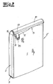
- the in the Fig. 1 to 3 illustrated film packages are suitable as packaging of bulk material, such as dry food for animals. They have front surfaces 1, 1 'formed by folding a film and side gussets 2, 2' and are closed by a bottom seam 3 and a top seam 4.
- the film is provided with a weakening line 5 for opening the package, which extends parallel to the top seam 4 over the entire bag width and also the side folds 2.
- the weakening line 5 may be a perforation or, if greater impermeability is required, a laser seam penetrating only one layer of the usually multilayer film.
- a head-side packaging section 6 is separable, wherein the tearing is facilitated by a finger lift 7 in one of the gussets 2. After opening the packaging, one of the two lateral folds can be used as a chute, while an area of the packaging adjacent to the pouring opening 8 remains closed on the upper side.
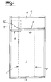
- a separating layer 9 made of a non-firmly sealable material is arranged in a region which forms the pouring opening 8 after opening the packaging.
- Parallel to the top seam 4 extends over the entire width of the package, a transverse seam 10, which is placed over the provided with the release layer 9 region of the film and only outside this area, the two front surfaces 1 and the inner surface of the other side fold 2 'with the respectively adjacent Front surface 1, 1 'firmly connects ( Fig. 2 ).
- the separating layer 9 prevents the opposite surfaces of the film packaging thermally bond under the action of the sealed seam and keeps the pouring opening 8 open.
- a at least two-layer film strip 11 is attached to the packaging inside of the film, which has a sealable connected to the inner surface of the package Layer and a separating layer 9 forming layer of a non-firmly sealable material.
- the film strip 11 consists for example of a composite material with a sealable layer of a polyolefin and a release layer 9 of a polyester.
- FIG. 1 and 2 A comparative consideration of Fig. 1 and 2 takes it that the film strip 11 is attached below the weakening line 5 on the inside of the package and extends into a region above the line of weakness 5. After opening the package, the film strip 11 forms an upwardly projecting chute 12, which facilitates the pouring of the contents.
- the release layer 9 of the film strip 11 can also be made of a peelable layer so that the portions of the film strip attached to opposite wall surfaces of the film package are superimposed and adhere to each other prior to initial use of the package by contact of their peelable layers.
- the easily peelable by hand peelable compound improves the tightness of the package, so that a good sealing effect is ensured even if the line of weakness 5 consists of a perforation.
- a closure strip 13 is disposed on the inside of the package in the region of the release layer 9, which is fastened below the weakening line 5 on the film and ends with a free end above the line of weakness 5.
- the free end of the closing meeting after opening the package - the pouring spout 8 across - attachable to the outside of the package.
- the closure strip 13 may consist of a self-adhesive adhesive strip or a Velcro strip, which cooperates with a corresponding counter-element 15 on the bag outer surface.
- the separating layer 9 consists of a separating lacquer applied in regions on the film of the packaging bag on the inside of the packaging, which barrier prevents thermal bonding of adjacent wall surfaces.
- the weakening line 5 has, in the region 16 of the film provided with the release lacquer, a contour which simulates an upwardly projecting chute 12.
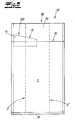
- the Fig. 5 to 8 show precursors for the production of the film packaging described.
- These are flat-lying film bags 17 for use in a bag filling plant, in which they are filled and then closed and finally formed into film packages with transverse sealing seams (4, 10) which extend over the entire width of the bag.
- the film bags each have front surfaces 1, 1 'formed by folding a film and side gussets 2, 2' and are closed on the underside by a bottom seam 3.
- the foil bags On the upper side, the foil bags have a filling opening 18 extending over the entire side of the bag.
- the film from which the film bags 17 are made is provided with a weakening line 5, along which a head-side bag section 19 can be separated from the film bag 17.
- a release layer 9 is arranged from a non-firmly sealable material.
- the release layer 9 covers a surface region 20 of the film, which is traversed by the weakening line 5.
- Fig. 5 is attached to the inside of the bag, at least a two-layer film strip 11 having a thermally firmly bonded to the film bag 17 sealable layer and the release layer 9 forming layer of a non-firmly sealable material.
- Foil strip 11 extends over the wall surface of the side fold 2 up to the front surfaces 1, 1 'and is attached over its entire length to the inside of the bag below the weakening line 5 on the inside of the foil bag 17 Fig. 6 ). Vertically, the film strip 11 extends into an area above the weakening line 5.
- the film strip 11 is closed to form an annular nozzle 21.
- the spout 21 is attached to the inner surface of the side gusset 2 and to one of the two front surfaces - here the front surface 1 '-.
- the not connected to the film bag portion 22 of the spout 21 adheres through a peelable compound 23 at the adjacent portions of the film strip 11 so that the spout 21 does not hinder the filling of the film bag.
- the spout 21 is also attached below the weakening line 5 on the inside of the film bag 17 and extends into a region above the line of weakness. 5
- the separating layer 9 consists of a release varnish applied to the film.
- the depiction also shows that the line of weakness in the region 16 of the film provided with the release lacquer has a contour which simulates an upwardly projecting chute 12.
- the in the Fig. 5 to 8 shown film bag 17 are prefabricated and then filled in a filling. After filling, the film bags 17 are closed by a top seal 4 and formed by attaching the transverse seam 10 to form a film. For attaching the head seam 4 and the transverse seam 10 same sealing tools can be used.
Landscapes
- Engineering & Computer Science (AREA)
- Mechanical Engineering (AREA)
- Bag Frames (AREA)
- Manufacture Of Macromolecular Shaped Articles (AREA)
- Wrappers (AREA)
- Packages (AREA)
Abstract
Description
Die Erfindung betrifft eine Folienverpackung, insbesondere für Schüttgut, die durch Falten einer Folie gebildete Frontflächen und Seitenfalten aufweist und durch eine Bodennaht sowie eine Kopfnaht verschlossen ist. Die Folie ist mit einer Schwächungslinie zum Öffnen der Verpackung versehen, entlang der ein kopfseitiger Verpackungsabschnitt abtrennbar ist. Nach dem Öffnen der Verpackung ist eine der beiden Seitenfalten als Schütte nutzbar, während ein an die Schüttöffnung angrenzender Bereich der Verpackung oberseitig verschlossen bleibt. Eine Folienverpackung mit den beschriebenen Merkmalen ist aus
Die Folienverpackung wird aus einem vorkonfektionierten Folienbeutel hergestellt, der oben offen ist und in einer Beutelbefüllanlage von oben befüllt sowie anschließend mit einer Quersiegelnaht, die sich über die gesamte Beutelbreite erstreckt, verschlossen wird. Bei einer aus
Der Erfindung liegt die Aufgabe zugrunde, eine Folienverpackung anzugeben, die nach ihrer Befüllung in einer Befüllanlage mit Siegelwerkzeugen, die sich über die gesamte Beutelbreite erstrecken, verschlossen und fertig gestellt werden kann.The invention has for its object to provide a film packaging, which can be closed and completed after their filling in a filling with sealing tools that extend over the entire bag width.
Ausgehend von einer Folienverpackung mit den eingangs beschriebenen Merkmalen wird die Aufgabe erfindungsgemäß dadurch gelöst, dass an der Verpackungsinnenseite der Folie in einem Bereich, der nach dem Öffnen der Verpackung die Schüttöffnung bildet, eine Trennschicht aus einem nicht fest versiegelbaren Material angeordnet ist und dass sich über die gesamte Breite der Verpackung eine Quersiegelnaht erstreckt, die über den mit der Trennschicht versehenen Bereich der Folie gelegt ist und lediglich außerhalb dieses Bereiches die beiden Frontflächen sowie die Innenfläche der anderen Seitenfalte mit der jeweils benachbarten Frontfläche fest verbindet. Unter nicht fest versiegelbare Materialien fallen nicht siegelfähige Materialien und thermisch siegelfähige Materialien, die beim thermischen Siegeln peelfähige Siegelnähte geringer Festigkeit bilden, welche bestimmungsgemäß von Hand ohne Zerstörung der Folie getrennt werden können. Die Trennschicht unterbindet eine feste thermische Verschweißung der Folienflächen im Bereich der späteren Schüttöffnung und stellt die Funktion dieses Bereiches sicher, ohne dass die Länge der Quersiegelnaht entsprechend angepasst werden muss. Daher können in der Befüllanlage gleiche Siegelwerkzeuge verwendet werden, um einerseits die Kopfsiegelnaht anzubringen und ferner diejenige Siegelnaht zu erzeugen, die nach dem Öffnen der Verpackung einen Teilbereich der Verpackung oberseitig verschließt. Es ergeben sich mehrere Möglichkeiten für die Ausgestaltung und Anordnung der Trennschicht.Starting from a film package with the features described above, the object is achieved in that on the packaging inside of the film in a region which forms the pour opening after opening the package, a release layer is arranged from a non-firmly sealable material and that about the entire width of the package extends a transverse sealing seam which is laid over the region of the film provided with the separating layer and firmly connects the two front surfaces and the inner surface of the other side fold with the respectively adjacent front surface only outside this region. Non-sealable materials include non-sealable materials and thermally sealable materials which, when thermally sealed, form peelable seal seams of low strength which can be purposefully separated by hand without destroying the film. The separating layer prevents a firm thermal welding of the foil surfaces in the area of the later pouring opening and ensures the function of this area without the length of the transverse sealing seam having to be adapted accordingly. For this reason, identical sealing tools can be used in the filling installation in order, on the one hand, to apply the top seal seam and, furthermore, to produce the sealing seam which closes a partial area of the packaging on the top side after opening the package. There are several possibilities for the design and arrangement of the separation layer.
Eine erfindungsgemäße Ausgestaltung sieht vor, dass an der Verpackungsinnenseite der Folieverpackung ein mindestens zweischichtiger Folienstreifen befestigt ist, der eine mit der Innenfläche der Verpackung verbundene siegelfähige Schicht und eine die Trennschicht bildende Schicht aus einem nicht fest versiegelbaren Material aufweist. Der Folienstreifen besteht beispielsweise aus einem Verbundmaterial mit einer siegelfähigen Schicht aus einem Polyolefin sowie einer Trennschicht aus einem nicht siegelfähigen Material, z B. Polyester. Der Folienstreifen kann ringförmig geschlossen sein. Ferner kann die Trennschicht aus einer peelfähigen Schicht bestehen, so dass die an gegenüberliegenden Wandflächen der Verpackung angebrachten Abschnitte des Folienstreifens aufeinander liegen und vor dem erstmaligen Gebrauch der Verpackung durch Kontakt der peelfähigen Schichten aufeinander haften. Die peelfähige Schicht kann aus einem peelenden Siegellack oder aus einer aufkaschierten Folie, die entsprechende Peeleigerischaften aufweist, bestehen. Die Peelschicht kann insbesondere eine Polyethylenschicht sein, die Polybuten enthält. Die Verbindung zwischen den peelfähigen Schichten lässt sich leicht von Hand lösen. Die Verbindung kann die Dichtigkeit des Beutels auch dann gewährleisten, wenn die Schwächungslinie aus einer Perforation besteht.An embodiment of the invention provides that at least one two-layer film strip is attached to the packaging inside of the film packaging having a sealable layer connected to the inner surface of the package and a layer of a non-firmly sealable material forming the release layer. The film strip consists for example of a composite material with a sealable layer of a polyolefin and a release layer of a non-sealable material, for example polyester. The foil strip can be closed annularly. Furthermore, the Separating layer of a peelable layer, so that the attached to opposite wall surfaces of the packaging portions of the film strip are superimposed and adhere to each other before the first use of the packaging by contact of the peelable layers. The peelable layer can consist of an exfoliating sealing wax or of a laminated foil which has corresponding peeligerishities. The peel layer may in particular be a polyethylene layer containing polybutene. The connection between the peelable layers can be easily released by hand. The connection can ensure the tightness of the bag even if the line of weakness consists of a perforation.
Vorzugsweise ist der Folienstreifen unterhalb der Schwächungslinie an der Innenseite der Verpackung befestigt und erstreckt sich bis in einen Bereich oberhalb der Schwächungslinie, ohne mit der Innenseite der Verpackung oberhalb der Schwächungslinie verbunden zu sein. Nach dem Öffnen der Verpackung bildet der Folienstreifen dann eine nach oben vorstehende Schütte, die das Ausschütten des Füllguts erleichtert.Preferably, the film strip is secured below the weakening line on the inside of the package and extends into an area above the line of weakness without being connected to the inside of the package above the line of weakness. After opening the package, the film strip then forms an upwardly projecting chute, which facilitates the pouring of the contents.
Eine alternative Ausgestaltung der Erfindung sieht vor, dass die Trennschicht aus einem auf die Folie aufgebrachten Trennlack besteht, der nicht siegelfähig ist und das Durchschweißen verhindert. Wenn die Folienverpackung durch Abtrennen des Kopfstückes geöffnet wird, kann eine nach oben vorstehende Schütte dadurch realisiert werden, dass die Schwächungslinie in dem mit dem Trennlack versehenen Bereich der Folie eine entsprechende Kontur aufweist, d. h. eine Kontur, die eine nach oben vorstehende Schütte nachbildet.An alternative embodiment of the invention provides that the separating layer consists of a release varnish applied to the film, which is not sealable and prevents through welding. If the film package is opened by severing the header, an upwardly projecting chute may be realized by having the line of weakness in the region of the film provided with the release coating having a corresponding contour, i. H. a contour that simulates an upwardly projecting chute.
Für alle zuvor beschriebenen Ausgestaltungen lässt sich eine weitere Funktionsverbesserung der Folienverpackung erreichen, indem an der Innenseite der Verpackung im Bereich der Trennschicht ein Verschlussstreffen angeordnet wird, der unterhalb der Schwächungslinie an der Folie befestigt ist und mit einem freien Ende oberhalb der Schwächungslinie endet. Das freie Ende des Verschlussstreifens ist nach dem Öffnen der Verpackung - die Schüttöffnung dabei übergreifend - an der Verpackungsaußenseite befestigbar. Hierbei wird der obere Rand der Schüttöffnung umgefaltet und dadurch auch verschlossen. Als Verschlussstreifen kommen Klebestreifen oder Streifen eines Kiettverschlusses in Betracht.For all embodiments described above, a further improvement in the function of the film packaging can be achieved by arranging a closing meeting on the inside of the packaging in the region of the separating layer, which is fastened to the film below the weakening line and with a free end above the line of weakness ends. The free end of the closure strip can be fastened to the outside of the packaging after the packaging has been opened - the pouring opening in cross-section. Here, the upper edge of the pouring opening is folded over and thereby closed. Adhesive strips or strips of a Kiett closure come into consideration as closure strips.
Gegenstand der Erfindung ist ferner ein flachliegender Folienbeutel nach Anspruch 10 zur Verwendung in einer Beutelbefüllanlage, in der der Folienbeutel befüllbar und mit Quersiegelnähten, die sich über die gesamte Beutelbreite erstrecken, zu einer Folienverpackung mit den zuvor beschriebenen Merkmalen schließbar ist. Vorteilhafte Ausgestaltungen sind in den Ansprüchen 11 bis 16 beschrieben.The invention furthermore relates to a flat foil pouch according to
Die Erfindung wird im Folgenden anhand einer lediglich ein Ausführungsbeispiel darstellenden Zeichnung erläutert. Es zeigen schematisch:
- Fig.1
- eine ungeöffnete Folienverpackung in perspektivischer Darstellung,
- Fig. 2
- die Folienverpackung gemäß
Fig. 1 nach dem Öffnen, - Fig. 3 und 4
- weitere Ausgestaltungen der Folienverpackung,
- Fig. 5
- einen noch unverschlossenen Folienbeutel zur Verwendung in einer Beutelbefüllanlage in einer Seitenansicht,
- Fig. 6
- den in
Fig. 5 dargestellten Folienbeutel in der Draufsicht; - Fig. 7 und 8
- weitere Ausgestaltungen des Folienbeutels.
- Fig.1
- an unopened foil packaging in perspective,
- Fig. 2
- the foil packaging according to
Fig. 1 After opening, - 3 and 4
- further embodiments of the foil packaging,
- Fig. 5
- an unopened foil pouch for use in a bag filling plant in a side view,
- Fig. 6
- the in
Fig. 5 illustrated film bag in plan view; - FIGS. 7 and 8
- further embodiments of the film bag.
Die in den
An der Verpackungsinnenseite der Folie ist in einem Bereich, der nach dem Öffnen der Verpackung die Schüttöffnung 8 bildet, eine Trennschicht 9 aus einem nicht fest versiegelbaren Material angeordnet. Parallel zur Kopfnaht 4 erstreckt sich über die gesamte Breite der Verpackung eine Quersiegelnaht 10, die über den mit der Trennschicht 9 versehenen Bereich der Folie gelegt ist und lediglich außerhalb dieses Bereiches die beiden Frontflächen 1 sowie die Innenfläche der anderen Seitenfalte 2' mit der jeweils benachbarten Frontfläche 1, 1' fest verbindet (
In dem in den
Einer vergleichenden Betrachtung der
Die Trennschicht 9 des Folienstreifens 11 kann auch aus einer peelfähigen Schicht bestehen, so dass die an gegenüberliegenden Wandflächen der Folienverpackung angebrachten Abschnitte des Folienstreifens aufeinander liegen und vor dem erstmaligen Gebrauch der Verpackung durch Kontakt ihrer peelfähigen Schichten aneinander haften. Die von Hand leicht lösbare peelfähige Verbindung verbessert die Dichtigkeit der Verpackung, so dass eine gute Dichtwirkung auch dann gewährleistet ist, wenn die Schwächungslinie 5 aus einer Perforation besteht.The
Bei dem in
Im Ausführungsbeispiel der
Die
Im Ausführungsbeispiel der
Im Ausführungsbeispiel der
Die in den
Claims (16)
wobei die Folie mit einer Schwächungslinie (5) zum Öffnen der Verpackung versehen ist, entlang der ein kopfseitiger Verpackungsabschnitt (6) abtrennbar ist, und
wobei nach dem Öffnen der Verpackung eine der beiden Seitenfalten (2) als Schütte nutzbar ist, während ein an die Schüttöffnung (8) angrenzender Bereich der Verpackung oberseitig verschlossen bleibt,
dadurch gekennzeichnet, dass an der Verpackungsinnenseite der Folie in einem Bereich, der nach dem Öffnen der Verpackung die Schüttöffnung (8) bildet, eine Trennschicht (9) aus einem nicht fest versiegelbaren Material angeordnet ist und dass sich über die gesamte Breite der Verpackung eine Quersiegelnaht (10) erstreckt, die über den mit der Trennschicht (9) versehenen Bereich der Folie gelegt ist und lediglich außerhalb dieses Bereiches die Frontflächen (1, 1') sowie die Innenfläche der anderen Seitenfalte (2') mit der jeweils benachbarten Frontfläche (1,1') verbindet.Film packaging, in particular for bulk material, which has front surfaces (1, 1 ') and side folds (2, 2') formed by folding a film and is closed by a bottom seam (3) and a top seam (4),
the film being provided with a weakening line (5) for opening the package, along which a head-side wrapping section (6) is separable, and
wherein one of the two lateral folds (2) can be used as a chute after opening the packaging, while an area of the packaging adjacent to the pouring opening (8) remains closed on the upper side,
characterized in that on the inside of the packaging film in a region which forms the pouring opening (8) after opening the package, a release layer (9) is arranged from a non-firmly sealable material and that over the entire width of the package a transverse seam (10) which is laid over the region of the film provided with the separating layer (9) and only outside this region the front surfaces (1, 1 ') and the inner surface of the other lateral folds (2') with the respectively adjacent front surface (1 , 1 ') connects.
wobei der Folienbeutel (17) durch Falten einer Folie gebildete Frontflächen (1. 1') und Seitenfalten (2, 2') aufweist sowie unterseitig durch eine Bodennaht (3) geschlossen ist und oberseitig eine sich über die gesamte Beutelbreite erstreckende Füllöffnung (18) aufweist,
wobei die Folie mit einer Schwächungslinie (5) versehen ist, entlang der ein kopfseitiger Beutelabschnitt (19) von dem Folienbeutel (17) abtrennbar ist,
dadurch gekennzeichnet, dass an der Innenfläche einer der beiden Seitenfalten (2) sowie an den zur Seitenfalte (2) benachbarten Abschnitten der beiden Frontflächen (1, 1') eine Trennschicht (9) aus einem nicht fest versiegelbaren Material angeordnet ist.Flat foil pouch for use in a bag filling line, in which the foil pouch can be filled and closed with transverse sealing seams that extend over the entire width of the pouch to form a foil packaging according to one of claims 1 to 9,
wherein the film bag (17) by folding a film formed front surfaces (1. 1 ') and gussets (2, 2') and the underside by a bottom seam (3) is closed and the top side over the entire bag width extending filling opening (18) having,
the film being provided with a weakening line (5) along which a head-side bag portion (19) is separable from the film bag (17),
characterized in that on the inner surface of one of the two side folds (2) and on the side fold (2) adjacent portions of the two front surfaces (1, 1 ') a release layer (9) is arranged from a non-firmly sealable material.
wobei die Tülle (21) nur an der Innenfläche der Seitenfalte (2) sowie an einer der beiden Frontflächen (1 oder 1') befestigt ist, und dass der mit dem Folienbeutel nicht verbundene Abschnitt der Tülle (21) durch eine peelfähige Verbindung (23) an den benachbarten Abschnitten des Folienstreifen (11) haftet.Flat foil pouch according to claim 12, characterized in that the film strip (11) is closed to form an annular spout (21),
the grommet (21) being fastened only to the inner surface of the lateral fold (2) and to one of the two front surfaces (1 or 1 '), and in that the portion of the grommet (21) not connected to the foil pouch is joined by a peelable connection (23 ) adheres to the adjacent portions of the film strip (11).
Priority Applications (1)
| Application Number | Priority Date | Filing Date | Title |
|---|---|---|---|
| PL09005048T PL2113467T3 (en) | 2008-05-03 | 2009-04-06 | Film packaging, in particular for bulk material |
Applications Claiming Priority (1)
| Application Number | Priority Date | Filing Date | Title |
|---|---|---|---|
| DE202008006099U DE202008006099U1 (en) | 2008-05-03 | 2008-05-03 | Foil packaging, especially for bulk material |
Publications (2)
| Publication Number | Publication Date |
|---|---|
| EP2113467A1 true EP2113467A1 (en) | 2009-11-04 |
| EP2113467B1 EP2113467B1 (en) | 2011-08-03 |
Family
ID=40888237
Family Applications (1)
| Application Number | Title | Priority Date | Filing Date |
|---|---|---|---|
| EP09005048A Not-in-force EP2113467B1 (en) | 2008-05-03 | 2009-04-06 | Film packaging, in particular for bulk material |
Country Status (4)
| Country | Link |
|---|---|
| EP (1) | EP2113467B1 (en) |
| AT (1) | ATE518781T1 (en) |
| DE (1) | DE202008006099U1 (en) |
| PL (1) | PL2113467T3 (en) |
Families Citing this family (1)
| Publication number | Priority date | Publication date | Assignee | Title |
|---|---|---|---|---|
| FR2973350B1 (en) * | 2011-03-30 | 2014-06-20 | Veriplast Flexible | PACKAGING BAG IN PLASTIC MATERIAL |
Citations (7)
| Publication number | Priority date | Publication date | Assignee | Title |
|---|---|---|---|---|
| US3282412A (en) * | 1963-11-06 | 1966-11-01 | Wayne V Rodgers | Valved mixing container or package |
| DE2647399A1 (en) * | 1975-10-22 | 1977-05-05 | Alusuisse | Self closing valve for plastics vessel opening - has valve opened by drinking straw and welded to main vessel |
| EP0608451A1 (en) * | 1993-01-27 | 1994-08-03 | Rovema Verpackungsmaschinen Gmbh | Folding bag |
| EP0778217A1 (en) * | 1995-12-08 | 1997-06-11 | Bayyomi, Fawzi Ali | Packaging container with flexible walls |
| JP2001206391A (en) * | 2000-01-28 | 2001-07-31 | Uni Charm Corp | Package body |
| WO2005007528A1 (en) | 2003-07-11 | 2005-01-27 | Mars, Incorporated | Food bag with pouring spout |
| DE102006029119A1 (en) | 2006-06-22 | 2007-07-05 | Nordenia Deutschland Halle Gmbh Werk Steinfeld | Film bag, has folding edges between first lateral edge and the front surface and rear surface, which are stiffends by longitudinal sealed seams, which extend up to top sealing seam |
-
2008
- 2008-05-03 DE DE202008006099U patent/DE202008006099U1/en not_active Expired - Lifetime
-
2009
- 2009-04-06 PL PL09005048T patent/PL2113467T3/en unknown
- 2009-04-06 AT AT09005048T patent/ATE518781T1/en active
- 2009-04-06 EP EP09005048A patent/EP2113467B1/en not_active Not-in-force
Patent Citations (7)
| Publication number | Priority date | Publication date | Assignee | Title |
|---|---|---|---|---|
| US3282412A (en) * | 1963-11-06 | 1966-11-01 | Wayne V Rodgers | Valved mixing container or package |
| DE2647399A1 (en) * | 1975-10-22 | 1977-05-05 | Alusuisse | Self closing valve for plastics vessel opening - has valve opened by drinking straw and welded to main vessel |
| EP0608451A1 (en) * | 1993-01-27 | 1994-08-03 | Rovema Verpackungsmaschinen Gmbh | Folding bag |
| EP0778217A1 (en) * | 1995-12-08 | 1997-06-11 | Bayyomi, Fawzi Ali | Packaging container with flexible walls |
| JP2001206391A (en) * | 2000-01-28 | 2001-07-31 | Uni Charm Corp | Package body |
| WO2005007528A1 (en) | 2003-07-11 | 2005-01-27 | Mars, Incorporated | Food bag with pouring spout |
| DE102006029119A1 (en) | 2006-06-22 | 2007-07-05 | Nordenia Deutschland Halle Gmbh Werk Steinfeld | Film bag, has folding edges between first lateral edge and the front surface and rear surface, which are stiffends by longitudinal sealed seams, which extend up to top sealing seam |
Also Published As
| Publication number | Publication date |
|---|---|
| EP2113467B1 (en) | 2011-08-03 |
| ATE518781T1 (en) | 2011-08-15 |
| DE202008006099U1 (en) | 2009-09-10 |
| PL2113467T3 (en) | 2011-12-30 |
Similar Documents
| Publication | Publication Date | Title |
|---|---|---|
| EP2186743B1 (en) | Film packaging bag | |
| EP2148820B1 (en) | Sheet-material packaging bag | |
| EP2032454B2 (en) | Film bag | |
| EP1712482B1 (en) | Bag | |
| EP2481678B1 (en) | Flat film bag for packaging bulk products | |
| EP0476428A1 (en) | Package, especially for compressed articles | |
| DE3808303A1 (en) | SQUARE FLAT GINGLE PACK AND METHOD FOR THE PRODUCTION THEREOF | |
| DE2458753A1 (en) | CARDBOARD CONTAINER | |
| EP0900746A2 (en) | Gusseted pouch | |
| DE3901503A1 (en) | EASY TO OPEN PACKING | |
| DE1486576A1 (en) | Easy to open bag | |
| DE3004940A1 (en) | ZIPPER ON A DOUBLE BAG FOR SCHUETTGUETER | |
| DE3835721C2 (en) | ||
| DE102005026903A1 (en) | Tubular bag container, for lightweight loose or solid contents, has a fixed tab to be held firmly while a cover tab is pulled to open the cover along a nominal tearing line | |
| EP0712787A1 (en) | Container with dispersing opening which is closed by a cover strip | |
| EP2368706A1 (en) | Method for producing a gusset bag | |
| DE19947296C2 (en) | Flat gable composite packaging provided with a reclosable spout and process for its production | |
| DE3336731C2 (en) | Sack preferably made of plastic film, in particular valve sack | |
| EP2113467B1 (en) | Film packaging, in particular for bulk material | |
| EP0553413B1 (en) | Recloseable bag | |
| EP0308807A2 (en) | Tearable package for foods or the like | |
| WO2016156296A1 (en) | Removable functional label for a liquid container | |
| EP1218255B1 (en) | Method for sealing a pouring opening of a container | |
| DE102015121540A1 (en) | Resealable bag | |
| AT508995B1 (en) | RE-SEALABLE PACKAGING |
Legal Events
| Date | Code | Title | Description |
|---|---|---|---|
| PUAI | Public reference made under article 153(3) epc to a published international application that has entered the european phase |
Free format text: ORIGINAL CODE: 0009012 |
|
| 17P | Request for examination filed |
Effective date: 20090820 |
|
| AK | Designated contracting states |
Kind code of ref document: A1 Designated state(s): AT BE BG CH CY CZ DE DK EE ES FI FR GB GR HR HU IE IS IT LI LT LU LV MC MK MT NL NO PL PT RO SE SI SK TR |
|
| GRAP | Despatch of communication of intention to grant a patent |
Free format text: ORIGINAL CODE: EPIDOSNIGR1 |
|
| GRAS | Grant fee paid |
Free format text: ORIGINAL CODE: EPIDOSNIGR3 |
|
| GRAA | (expected) grant |
Free format text: ORIGINAL CODE: 0009210 |
|
| AK | Designated contracting states |
Kind code of ref document: B1 Designated state(s): AT BE BG CH CY CZ DE DK EE ES FI FR GB GR HR HU IE IS IT LI LT LU LV MC MK MT NL NO PL PT RO SE SI SK TR |
|
| REG | Reference to a national code |
Ref country code: GB Ref legal event code: FG4D Free format text: NOT ENGLISH |
|
| REG | Reference to a national code |
Ref country code: CH Ref legal event code: EP |
|
| REG | Reference to a national code |
Ref country code: IE Ref legal event code: FG4D Free format text: LANGUAGE OF EP DOCUMENT: GERMAN |
|
| REG | Reference to a national code |
Ref country code: DE Ref legal event code: R096 Ref document number: 502009001012 Country of ref document: DE Effective date: 20110929 |
|
| REG | Reference to a national code |
Ref country code: NL Ref legal event code: VDEP Effective date: 20110803 |
|
| REG | Reference to a national code |
Ref country code: PL Ref legal event code: T3 |
|
| LTIE | Lt: invalidation of european patent or patent extension |
Effective date: 20110803 |
|
| PG25 | Lapsed in a contracting state [announced via postgrant information from national office to epo] |
Ref country code: PT Free format text: LAPSE BECAUSE OF FAILURE TO SUBMIT A TRANSLATION OF THE DESCRIPTION OR TO PAY THE FEE WITHIN THE PRESCRIBED TIME-LIMIT Effective date: 20111205 Ref country code: LT Free format text: LAPSE BECAUSE OF FAILURE TO SUBMIT A TRANSLATION OF THE DESCRIPTION OR TO PAY THE FEE WITHIN THE PRESCRIBED TIME-LIMIT Effective date: 20110803 Ref country code: HR Free format text: LAPSE BECAUSE OF FAILURE TO SUBMIT A TRANSLATION OF THE DESCRIPTION OR TO PAY THE FEE WITHIN THE PRESCRIBED TIME-LIMIT Effective date: 20110803 Ref country code: NO Free format text: LAPSE BECAUSE OF FAILURE TO SUBMIT A TRANSLATION OF THE DESCRIPTION OR TO PAY THE FEE WITHIN THE PRESCRIBED TIME-LIMIT Effective date: 20111103 Ref country code: FI Free format text: LAPSE BECAUSE OF FAILURE TO SUBMIT A TRANSLATION OF THE DESCRIPTION OR TO PAY THE FEE WITHIN THE PRESCRIBED TIME-LIMIT Effective date: 20110803 Ref country code: NL Free format text: LAPSE BECAUSE OF FAILURE TO SUBMIT A TRANSLATION OF THE DESCRIPTION OR TO PAY THE FEE WITHIN THE PRESCRIBED TIME-LIMIT Effective date: 20110803 Ref country code: SE Free format text: LAPSE BECAUSE OF FAILURE TO SUBMIT A TRANSLATION OF THE DESCRIPTION OR TO PAY THE FEE WITHIN THE PRESCRIBED TIME-LIMIT Effective date: 20110803 Ref country code: IS Free format text: LAPSE BECAUSE OF FAILURE TO SUBMIT A TRANSLATION OF THE DESCRIPTION OR TO PAY THE FEE WITHIN THE PRESCRIBED TIME-LIMIT Effective date: 20111203 |
|
| PG25 | Lapsed in a contracting state [announced via postgrant information from national office to epo] |
Ref country code: CY Free format text: LAPSE BECAUSE OF FAILURE TO SUBMIT A TRANSLATION OF THE DESCRIPTION OR TO PAY THE FEE WITHIN THE PRESCRIBED TIME-LIMIT Effective date: 20110803 Ref country code: GR Free format text: LAPSE BECAUSE OF FAILURE TO SUBMIT A TRANSLATION OF THE DESCRIPTION OR TO PAY THE FEE WITHIN THE PRESCRIBED TIME-LIMIT Effective date: 20111104 Ref country code: SI Free format text: LAPSE BECAUSE OF FAILURE TO SUBMIT A TRANSLATION OF THE DESCRIPTION OR TO PAY THE FEE WITHIN THE PRESCRIBED TIME-LIMIT Effective date: 20110803 Ref country code: LV Free format text: LAPSE BECAUSE OF FAILURE TO SUBMIT A TRANSLATION OF THE DESCRIPTION OR TO PAY THE FEE WITHIN THE PRESCRIBED TIME-LIMIT Effective date: 20110803 |
|
| REG | Reference to a national code |
Ref country code: IE Ref legal event code: FD4D |
|
| PG25 | Lapsed in a contracting state [announced via postgrant information from national office to epo] |
Ref country code: CZ Free format text: LAPSE BECAUSE OF FAILURE TO SUBMIT A TRANSLATION OF THE DESCRIPTION OR TO PAY THE FEE WITHIN THE PRESCRIBED TIME-LIMIT Effective date: 20110803 Ref country code: SK Free format text: LAPSE BECAUSE OF FAILURE TO SUBMIT A TRANSLATION OF THE DESCRIPTION OR TO PAY THE FEE WITHIN THE PRESCRIBED TIME-LIMIT Effective date: 20110803 Ref country code: IE Free format text: LAPSE BECAUSE OF FAILURE TO SUBMIT A TRANSLATION OF THE DESCRIPTION OR TO PAY THE FEE WITHIN THE PRESCRIBED TIME-LIMIT Effective date: 20110803 |
|
| PG25 | Lapsed in a contracting state [announced via postgrant information from national office to epo] |
Ref country code: EE Free format text: LAPSE BECAUSE OF FAILURE TO SUBMIT A TRANSLATION OF THE DESCRIPTION OR TO PAY THE FEE WITHIN THE PRESCRIBED TIME-LIMIT Effective date: 20110803 Ref country code: RO Free format text: LAPSE BECAUSE OF FAILURE TO SUBMIT A TRANSLATION OF THE DESCRIPTION OR TO PAY THE FEE WITHIN THE PRESCRIBED TIME-LIMIT Effective date: 20110803 |
|
| PLBE | No opposition filed within time limit |
Free format text: ORIGINAL CODE: 0009261 |
|
| STAA | Information on the status of an ep patent application or granted ep patent |
Free format text: STATUS: NO OPPOSITION FILED WITHIN TIME LIMIT |
|
| PG25 | Lapsed in a contracting state [announced via postgrant information from national office to epo] |
Ref country code: DK Free format text: LAPSE BECAUSE OF FAILURE TO SUBMIT A TRANSLATION OF THE DESCRIPTION OR TO PAY THE FEE WITHIN THE PRESCRIBED TIME-LIMIT Effective date: 20110803 |
|
| 26N | No opposition filed |
Effective date: 20120504 |
|
| REG | Reference to a national code |
Ref country code: DE Ref legal event code: R097 Ref document number: 502009001012 Country of ref document: DE Effective date: 20120504 |
|
| BERE | Be: lapsed |
Owner name: NORDENIA DEUTSCHLAND HALLE G.M.B.H. Effective date: 20120430 |
|
| PG25 | Lapsed in a contracting state [announced via postgrant information from national office to epo] |
Ref country code: MC Free format text: LAPSE BECAUSE OF NON-PAYMENT OF DUE FEES Effective date: 20120430 |
|
| PG25 | Lapsed in a contracting state [announced via postgrant information from national office to epo] |
Ref country code: BE Free format text: LAPSE BECAUSE OF NON-PAYMENT OF DUE FEES Effective date: 20120430 |
|
| PG25 | Lapsed in a contracting state [announced via postgrant information from national office to epo] |
Ref country code: MK Free format text: LAPSE BECAUSE OF FAILURE TO SUBMIT A TRANSLATION OF THE DESCRIPTION OR TO PAY THE FEE WITHIN THE PRESCRIBED TIME-LIMIT Effective date: 20110803 |
|
| PG25 | Lapsed in a contracting state [announced via postgrant information from national office to epo] |
Ref country code: ES Free format text: LAPSE BECAUSE OF FAILURE TO SUBMIT A TRANSLATION OF THE DESCRIPTION OR TO PAY THE FEE WITHIN THE PRESCRIBED TIME-LIMIT Effective date: 20111114 |
|
| PG25 | Lapsed in a contracting state [announced via postgrant information from national office to epo] |
Ref country code: BG Free format text: LAPSE BECAUSE OF FAILURE TO SUBMIT A TRANSLATION OF THE DESCRIPTION OR TO PAY THE FEE WITHIN THE PRESCRIBED TIME-LIMIT Effective date: 20111103 |
|
| PG25 | Lapsed in a contracting state [announced via postgrant information from national office to epo] |
Ref country code: MT Free format text: LAPSE BECAUSE OF FAILURE TO SUBMIT A TRANSLATION OF THE DESCRIPTION OR TO PAY THE FEE WITHIN THE PRESCRIBED TIME-LIMIT Effective date: 20110803 |
|
| REG | Reference to a national code |
Ref country code: CH Ref legal event code: PL |
|
| PG25 | Lapsed in a contracting state [announced via postgrant information from national office to epo] |
Ref country code: LI Free format text: LAPSE BECAUSE OF NON-PAYMENT OF DUE FEES Effective date: 20130430 Ref country code: CH Free format text: LAPSE BECAUSE OF NON-PAYMENT OF DUE FEES Effective date: 20130430 |
|
| PG25 | Lapsed in a contracting state [announced via postgrant information from national office to epo] |
Ref country code: TR Free format text: LAPSE BECAUSE OF FAILURE TO SUBMIT A TRANSLATION OF THE DESCRIPTION OR TO PAY THE FEE WITHIN THE PRESCRIBED TIME-LIMIT Effective date: 20110803 |
|
| PG25 | Lapsed in a contracting state [announced via postgrant information from national office to epo] |
Ref country code: LU Free format text: LAPSE BECAUSE OF NON-PAYMENT OF DUE FEES Effective date: 20120406 |
|
| PG25 | Lapsed in a contracting state [announced via postgrant information from national office to epo] |
Ref country code: HU Free format text: LAPSE BECAUSE OF FAILURE TO SUBMIT A TRANSLATION OF THE DESCRIPTION OR TO PAY THE FEE WITHIN THE PRESCRIBED TIME-LIMIT Effective date: 20090406 |
|
| REG | Reference to a national code |
Ref country code: FR Ref legal event code: PLFP Year of fee payment: 7 |
|
| REG | Reference to a national code |
Ref country code: AT Ref legal event code: MM01 Ref document number: 518781 Country of ref document: AT Kind code of ref document: T Effective date: 20140406 |
|
| PGFP | Annual fee paid to national office [announced via postgrant information from national office to epo] |
Ref country code: GB Payment date: 20150420 Year of fee payment: 7 Ref country code: DE Payment date: 20150422 Year of fee payment: 7 |
|
| PG25 | Lapsed in a contracting state [announced via postgrant information from national office to epo] |
Ref country code: AT Free format text: LAPSE BECAUSE OF NON-PAYMENT OF DUE FEES Effective date: 20140406 |
|
| PGFP | Annual fee paid to national office [announced via postgrant information from national office to epo] |
Ref country code: IT Payment date: 20150424 Year of fee payment: 7 Ref country code: FR Payment date: 20150421 Year of fee payment: 7 Ref country code: PL Payment date: 20150401 Year of fee payment: 7 |
|
| REG | Reference to a national code |
Ref country code: DE Ref legal event code: R119 Ref document number: 502009001012 Country of ref document: DE |
|
| GBPC | Gb: european patent ceased through non-payment of renewal fee |
Effective date: 20160406 |
|
| REG | Reference to a national code |
Ref country code: FR Ref legal event code: ST Effective date: 20161230 |
|
| PG25 | Lapsed in a contracting state [announced via postgrant information from national office to epo] |
Ref country code: FR Free format text: LAPSE BECAUSE OF NON-PAYMENT OF DUE FEES Effective date: 20160502 Ref country code: GB Free format text: LAPSE BECAUSE OF NON-PAYMENT OF DUE FEES Effective date: 20160406 Ref country code: DE Free format text: LAPSE BECAUSE OF NON-PAYMENT OF DUE FEES Effective date: 20161101 |
|
| PG25 | Lapsed in a contracting state [announced via postgrant information from national office to epo] |
Ref country code: IT Free format text: LAPSE BECAUSE OF NON-PAYMENT OF DUE FEES Effective date: 20160406 |
|
| PG25 | Lapsed in a contracting state [announced via postgrant information from national office to epo] |
Ref country code: PL Free format text: LAPSE BECAUSE OF NON-PAYMENT OF DUE FEES Effective date: 20160406 |