EP2113387B1 - Druckplattenhandhabungsvorrichtung - Google Patents
Druckplattenhandhabungsvorrichtung Download PDFInfo
- Publication number
- EP2113387B1 EP2113387B1 EP20090158841 EP09158841A EP2113387B1 EP 2113387 B1 EP2113387 B1 EP 2113387B1 EP 20090158841 EP20090158841 EP 20090158841 EP 09158841 A EP09158841 A EP 09158841A EP 2113387 B1 EP2113387 B1 EP 2113387B1
- Authority
- EP
- European Patent Office
- Prior art keywords
- printing plate
- handling device
- printing
- clamping
- manner
- Prior art date
- Legal status (The legal status is an assumption and is not a legal conclusion. Google has not performed a legal analysis and makes no representation as to the accuracy of the status listed.)
- Not-in-force
Links
- 238000005452 bending Methods 0.000 claims description 3
- 230000004323 axial length Effects 0.000 description 3
- 238000001514 detection method Methods 0.000 description 3
- 230000018109 developmental process Effects 0.000 description 2
- 230000001419 dependent effect Effects 0.000 description 1
- 230000006641 stabilisation Effects 0.000 description 1
- 238000011105 stabilization Methods 0.000 description 1
Images

Classifications
-
- B—PERFORMING OPERATIONS; TRANSPORTING
- B41—PRINTING; LINING MACHINES; TYPEWRITERS; STAMPS
- B41F—PRINTING MACHINES OR PRESSES
- B41F27/00—Devices for attaching printing elements or formes to supports
- B41F27/12—Devices for attaching printing elements or formes to supports for attaching flexible printing formes
- B41F27/1206—Feeding to or removing from the forme cylinder
-
- B—PERFORMING OPERATIONS; TRANSPORTING
- B41—PRINTING; LINING MACHINES; TYPEWRITERS; STAMPS
- B41P—INDEXING SCHEME RELATING TO PRINTING, LINING MACHINES, TYPEWRITERS, AND TO STAMPS
- B41P2227/00—Mounting or handling printing plates; Forming printing surfaces in situ
- B41P2227/60—Devices for transferring printing plates
Definitions
- the invention relates to a printing plate handling device.
- Out DE 10 2004 052 021 A1 is a printing form manipulator for mounting or unmounting a printing forme in a printing unit known.
- the printing form manipulator comprises a movable manipulator arm, a manipulator head having a holding member for a printing forme formed as a sucker, a first joint which connects the manipulator head in at least one plane pivotally or only rotatably connected to the manipulator and a second joint in which the manipulator head in the at least one plane in the longitudinal direction of the manipulator arm is translationally movably connected to the manipulator arm.
- the present invention seeks to provide a novel printing plate handling device, can be handled with the printing plates without Einknickgefahr.
- the printing plate handling device serves for detecting a printing plate adjacent to an edge thereof, in particular adjacent to a bevelled leading edge or a beveled trailing edge of the printing plate, and comprising means for surface, frictionally fixing the pressure plate to be detected on a adjacent to an edge of the printing plate extending Surface area of the printing plate.
- the printing plate handling device comprises a device for the surface, frictional fixing of a printing plate to be detected on a surface region of the same extending adjacent to an edge of the printing plate.
- the flat, frictional fixing of the pressure plate to be detected is stiffened or stabilized during handling in the printing plate handling device, so that buckling of the printing plates can be reliably avoided even with large-format printing plates with short folding legs. With the handling device according to the invention can thus be avoided that large format printing plates are damaged during transport or other handling steps.
- the printing plate handling device comprises a device for register-correct detection of a printing plate.
- the invention relates to a printing plate handling device for handling especially large-format printing plates, as they are for. B. are used on commercial printing presses.
- the printing plate handling device 10 is used to detect the printing plate 11 in the region of a folded edge 12 of the printing plate 11, wherein the edge 12 is a leading edge or a trailing edge of the printing plate 11 can act.
- the printing plate handling device 10 comprises a device for surface, frictionally fixing the pressure plate 11 to be detected on a surface region thereof extending adjacent to the edge 12 of the pressure plate 11.
- a surface region thereof extending adjacent to the edge 12 of the pressure plate 11.
- the device for surface, frictional fixing of the pressure plate 11 to be detected by two clamping legs 13, 14 is formed.
- the clamping legs 13, 14 are connected to one another via spring elements 15 in such a way that the clamping legs 13, 14 are displaced relative to one another against the spring force of the spring elements 15, namely, can be pivoted relative to one another. Then, when the clamping legs 13, 14 are pivoted against each other against the spring force provided by the spring elements 15, a defined by the clamping legs 13, 14 clamping area 16 for inserting a to be handled with the printing plate handling device 10 printing plate 11 is opened.
- the clamping region 16 can then be closed for the frictional fixing of a pressure plate 11 introduced into the clamping region 16.
- Fig. 1 are the clamping legs 13, 14 in the clamping region 16 associated elastic abutment elements 17, between which the pressure plate 11 with the clamping area 16 closed and therefore with the help of the spring elements 15 to each other moving clamping legs 13, 14 is frictionally fixed.
- Fig. 2 is also the spring elements 15 associated with an elastic contact element 18 to which the introduced into the clamping region 16 pressure plate 11 comes with the introduced into the clamping region 16 edge 12 to the plant.
- the printing plate handling device 10 handling handles 19 associated.
- the printing plate handling device 10 can be detected by a printer, namely in particular when a pressure plate 11 is frictionally fixed to the printing plate handling device 10.
- the handling handles 19 are associated with one of the clamping legs 14.
- Fig. 1 furthermore recesses 20 introduced.
- the printing plate handling device 10 together with a frictionally fixed in the same pressure plate 11 to a pressure plate transport device, not shown, for.
- a printing plate transport carriage or a printing plate lift are suspended without a pressure plate 11 fixed to the pressure plate handling device 10 frictionally engaged with the pressure plate transport device and can be damaged by the same.
- the recesses 20 are inserted into the clamping leg 14. It is also possible to introduce 13 corresponding recesses in the clamping leg.
- the printing plate handling device according to the invention is characterized by a compact design and low weight. As a result, an easy handling and space-saving arrangement of a plurality of printing plate handling devices fixed printing plates on a printing plate transport device is possible.
- the printing plate handling device 10 preferably serves to receive a printing plate immediately after the leading and trailing edges of the printing plate have been folded in the region of a bending machine.
- the printing plate remains fixed during the entire transport path until transfer of the printing plate to a printing press or until tensioning of the printing plate on a forme cylinder of the printing press in the printing plate handling device 10.
- a printing plate fixed to the same can be transferred to the page register in the correct manner to a forme cylinder of a printing unit of a printing press.
- the printing plate handling apparatus 10 includes the Fig. 3 a device for register-correct detection of the pressure plate 11, wherein the means for register-correct detection of the pressure plate 11 on both sides of the clamping legs 13, 14 formed guide pins 21 has.
- the guide pins 21 are according to Fig. 3 in guide groove 22 of a printing plate supply table 23, in particular a table 23 of a printing plate bending device, are insertable such that a prepared on the printing plate supply table 23 pressure plate 21 is recorded in the clamping legs 13, 14 in register.
- a printing plate 11 to be received by the printing plate handling apparatus 10 is aligned in register with stops 24, 25 of the printing plate supplying table 23.
- the printing plate 11 thus aligned in register with the printing plate supply table 23 is then registered in register in the printing plate handling apparatus 10, namely via the cooperation of the guide pins 21 of the printing plate handling apparatus 10 and the guide groove 22 of the printing plate supply table 23.
- a registration in the printing plate handling device 10 correctly recorded printing plate 11 remains during the entire transport path to the transfer of the printing plate 11 to a printing unit of a printing press in register registration in the printing plate handling device 10, wherein in the transfer of the printing plate 11 to a printing unit of a printing machine, the guide pins 21 of Printing plate handling device 10 in guide groove of a printing unit, not shown, are insertable such that in the clamping legs 13, 14 of the printing plate handling device 10 registered register printing plate to the printing register in the correct register, namely correct page and diagonal register correct passed.
Landscapes
- Supply, Installation And Extraction Of Printed Sheets Or Plates (AREA)
Description
- Die Erfindung betrifft eine Druckplattenhandhabungsvorrichtung.
- Aus
DE 10 2004 052 021 A1 ist ein Druckformmanipulator zum Ein- oder Aushängen einer Druckform in einem Druckwerk bekannt. Der Druckformmanipulator umfasst einen bewegbaren Manipulatorarm, einen Manipulatorkopf, der ein als Sauger gebildetes Halteorgan für eine Druckform aufweist, ein erstes Gelenk, das den Manipulatorkopf in wenigstens einer Ebene schwenkbar oder nur drehbar mit dem Manipulatorarm verbindet und ein zweites Gelenk in dem der Manipulatorkopf in der wenigstens einen Ebene in Längsrichtung des Manipulatorarms translatorisch bewegbar mit dem Manipulatorarm verbunden ist. - Insbesondere bei als Illustrationsdruckmaschinen ausgebildeten Rollendruckmaschinen werden auf Formzylindern der Druckwerke der Druckmaschine Druckplatten gespannt, die sich über die gesamte axiale Länge der Formzylinder erstrecken. Mit zunehmender axialer Länge der Formzylinder nimmt dann auch die axiale Erstreckung der Druckplatten zu, wobei mit Zunahme der axialen Erstreckung der Druckplatten die Handhabung derselben immer schwieriger wird. So besteht bei der Handhabung von Druckplatten mit einer großen axialen Länge die Gefahr, dass die Druckplatten in Folge ihres Eigengewichts einknicken und beschädigt werden. Dies muss zuverlässig vermieden werden.
- Hiervon ausgehend liegt der vorliegenden Erfindung die Aufgabe zugrunde, eine neuartige Druckplattenhandhabungsvorrichtung zu schaffen, mit der Druckplatten ohne Einknickgefahr gehandhabt werden können.
- Diese Aufgabe wird durch eine Druckplattenhandhabungsvorrichtung gemäß Anspruch 1 gelöst. Die erfindungsgemäße Druckplattenhandhabungsvorrichtung dient dem Erfassen einer Druckplatte benachbart zu einer Kante derselben, insbesondere benachbart zu einer abgekanteten Vorlaufkante oder einer abgekanteten Nachlaufkante der Druckplatte, und umfasst eine Einrichtung zum flächigen, reibschlüssigen Fixieren der zu erfassenden Druckplatte an einem sich benachbart zu einer Kante der Druckplatte erstreckenden Oberflächenbereich der Druckplatte.
- Die erfindungsgemäße Druckplattenhandhabungsvorrichtung umfasst eine Einrichtung zum flächigen, reibschlüssigen Fixieren einer zu erfassenden Druckplatte an einem sich benachbart zu einer Kante der Druckplatte erstreckenden Oberflächenbereich derselben. Durch das flächige, reibschlüssige Fixieren der zu erfassenden Druckplatte wird dieselbe bei der Handhabung in der Druckplattenhandhabungsvorrichtung versteift bzw. stabilisiert, sodass selbst bei großformatigen Druckplatten mit kurzen Abkantschenkeln ein Einknicken der Druckplatten sicher vermieden werden kann. Mit der erfindungsgemäßen Handhabungsvorrichtung kann demnach vermieden werden, dass großformatige Druckplatten beim Transport oder sonstigen Handhabungsschritten beschädigt werden.
- Nach einer vorteilhaften Weiterbildung der Erfindung umfasst die Druckplattenhandhabungsvorrichtung eine Einrichtung zum registerrichtigen Erfassen einer Druckplatte.
- Bevorzugte Weiterbildungen der Erfindung ergeben sich aus den Unteransprüchen und der nachfolgenden Beschreibung. Ausführungsbeispiele der Erfindung werden, ohne hierauf beschränkt zu sein, an Hand der Zeichnung näher erläutert. Dabei zeigt:
- Fig. 1:
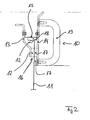
- eine perspektivische Ansicht einer erfindungsgemäßen Druckplattenhandhabungsvorrichtung;
- Fig. 2:
- die Druckplattenhandhabungsvorrichtung der
Fig. 1 in Seitenansicht; und - Fig. 3:
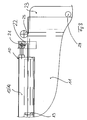
- eine ausschnittsweise Seitenansicht einer weiteren erfindungsgemäßen Druckplattenhandhabungsvorrichtung zusammen mit einem Druckplattenbereitstellungstisch.
- Die Erfindung betrifft eine Druckplattenhandhabungsvorrichtung zur Handhabung von insbesondere großformatigen Druckplatten, wie sie z. B. an Illustrationsdruckmaschinen zum Einsatz kommen.
-
Fig. 1 und2 zeigen eine erfindungsgemäße Druckplattenhandhabungsvorrichtung 10 zusammen mit einer von der Druckplattenhandhabungsvorrichtung 10 aufgenommenen Druckplatte 11. Die Druckplattenhandhabungsvorrichtung 10 dient dem Erfassen der Druckplatte 11 im Bereich einer abgekanteten Kante 12 der Druckplatte 11, wobei es sich bei der Kante 12 um eine Vorlaufkante oder eine Nachlaufkante der Druckplatte 11 handeln kann. - Die Druckplattenhandhabungsvorrichtung 10 umfasst eine Einrichtung zum flächigen, reibschlüssigen Fixieren der zu erfassenden Druckplatte 11 an einem sich benachbart zur Kante 12 der Druckplatte 11 erstreckenden Oberflächenbereich derselben. Durch dieses flächige, reibschlüssige Fixieren wird eine Versteifung und damit Stabilisierung der Druckplatte 11 im Bereich der Druckplattenhandhabungsvorrichtung 10 gewährleistet, sodass keine Gefahr besteht, dass beim Handhaben der Druckplatte 11 mit der Druckplattenhandhabungsvorrichtung 10 die Druckplatte 11 in Folge ihres Eigengewichts einknickt.
- Im gezeigten Ausführungsbeispiel der
Fig. 1 und2 wird die Einrichtung zum flächigen, reibschlüssigen Fixieren der zu erfassenden Druckplatte 11 von zwei Klemmschenkeln 13, 14 gebildet. Die Klemmschenkel 13, 14 sind über Federelemente 15 derart miteinander verbunden, dass die Klemmschenkel 13, 14 entgegen der Federkraft der Federelemente 15 zueinander verlagert, nämlich zueinander verschwenkt, werden können. Dann, wenn die Klemmschenkel 13, 14 entgegen der von den Federelementen 15 bereitgestellten Federkraft zueinander verschwenkt werden, wird ein von den Klemmschenkeln 13, 14 definierter Klemmbereich 16 zum Einführen einer mit der Druckplattenhandhabungsvorrichtung 10 handzuhabenden Druckplatte 11 geöffnet. - Durch die Federkraft der Federelemente 15 ist der Klemmbereich 16 dann zum reibschlüssigen Fixieren einer in den Klemmbereich 16 eingeführten Druckplatte 11 schließbar.
- Gemäß
Fig. 1 sind den Klemmschenkeln 13, 14 im Klemmbereich 16 elastische Anlageelemente 17 zugeordnet, zwischen denen die Druckplatte 11 bei geschlossenem Klemmbereich 16 und demnach bei mit Hilfe der Federelemente 15 aufeinander zu bewegten Klemmschenkeln 13, 14 reibschlüssig fixiert wird. GemäßFig. 2 ist ebenfalls den Federelementen 15 ein elastisches Anlageelement 18 zugeordnet, an welchem die in den Klemmbereich 16 eingeführte Druckplatte 11 mit der in den Klemmbereich 16 eingeführten Kante 12 zur Anlage kommt. - Gemäß
Fig. 1 ,2 sind der Druckplattenhandhabungsvorrichtung 10 Handhabungsgriffe 19 zugeordnet. Über die Handhabungsgriffe 19 kann die erfindungsgemäße Druckplattenhandhabungsvorrichtung 10 von einem Drucker erfasst werden, nämlich insbesondere dann, wenn an der Druckplattenhandhabungsvorrichtung 10 eine Druckplatte 11 reibschlüssig fixiert ist. Im Ausführungsbeispiel derFig. 1 und2 sind die Handhabungsgriffe 19 einem der Klemmschenkel 14 zugeordnet. - In die Druckplattenhandhabungsvorrichtung 19 sind gemäß
Fig. 1 weiterhin Ausnehmungen 20 eingebracht. Über die Ausnehmungen 20 kann die Druckplattenhandhabungsvorrichtung 10 zusammen mit einer in derselben reibschlüssig fixierten Druckplatte 11 an einer nicht gezeigten Druckplattentransporteinrichtung, z. B. einem Druckplattentransportwagen oder einem Druckplattenlift, eingehängt werden, ohne dass eine an der Druckplattenhandhabungsvorrichtung 10 reibschlüssig fixierte Druckplatte 11 mit der Druckplattentransporteinrichtung in Kontakt kommt und von derselben beschädigt werden kann. Im gezeigten Ausführungsbeispiel sind die Ausnehmungen 20 in den Klemmschenkel 14 eingebracht. Ebenso ist es möglich, auch in den Klemmschenkel 13 entsprechende Ausnehmungen einzubringen. - Zusätzlich zum reibschlüssigen Fixieren der Druckplatte 11 in der Druckplattenhandhabungseinrichtung 10 erfolgt eine formschlüssige Absicherung der Druckplatte 11 in der Druckplattenhandhabungsvorrichtung 10, nämlich über die in den Klemmbereich 16 hineinragende Kante 12 der Druckplatte 11. Hierdurch kann vermieden werden, dass eine Druckplatte 11 aus der Druckplattenhandhabungsvorrichtung 10 herausfällt.
- Die erfindungsgemäße Druckplattenhandhabungseinrichtung zeichnet sich durch eine kompakte Bauform und ein geringes Gewicht aus. Hierdurch ist eine leichte Handhabung und platzsparende Anordnung mehrerer an Druckplattenhandhabungsvorrichtungen fixierter Druckplatten auf einer Druckplattentransporteinrichtung möglich.
- Die erfindungsgemäße Druckplattenhandhabungsvorrichtung 10 dient vorzugsweise dem Aufnehmen einer Druckplatte unmittelbar nach dem Abkanten von Vorlaufende und Nachlaufende der Druckplatte im Bereich einer Biegemaschine. Vorzugsweise bleibt die Druckplatte während des gesamten Transportwegs bis zur Übergabe der Druckplatte an einer Druckmaschine bzw. bis zum Spannen der Druckplatte an einem Formzylinder der Druckmaschine in der Druckplattenhandhabungsvorrichtung 10 fixiert.
- Im gezeigten Ausführungsbeispiel der
Fig. 1 und2 erfolgt das reibschlüssige Fixieren der Druckplatte 11 in der Druckplattenhandhabungsvorrichtung 10 mit Hilfe der Klemmschenkel 13, 14, die über Federelemente 15 zusammengedrückt werden. Im Unterschied hierzu ist es auch möglich, die Erzeugung des Reibschlusses zum Fixieren einer Druckplatte in der Druckplattenhandhabungsvorrichtung 10 über eine als Vakuumsauger ausgebildete Ansaugeinrichtung bereitzustellen. - Mit der erfindungsgemäßen Druckplattenhandhabungsvorrichtung 10 kann eine an derselben fixierte Druckplatte seitenregisterrichtig an einen Formzylinder eines Druckwerks einer Druckmaschine übergeben werden.
-
Fig. 3 zeigt eine vorteilhafte Weiterbildung der Druckplattenhandhabungsvorrichtung 10 derFig. 1 und2 . So umfasst die Druckplattenhandhabungsvorrichtung 10 derFig. 3 eine Einrichtung zum registerrichtigen Erfassen der Druckplatte 11, wobei die Einrichtung zum registerrichtigen Erfassen der Druckplatte 11 zu beiden Seiten der Klemmschenkel 13, 14 ausgebildete Führungsstifte 21 aufweist. Die Führungsstifte 21 sind gemäßFig. 3 in Führungsnute 22 eines Druckplattenbereitstellungstischs 23, insbesondere eines Tischs 23 einer Druckplattenbiegeinrichtung, derart einführbar sind, dass eine am Druckplattenbereitstellungstisch 23 bereitgehaltene Druckplatte 21 in den Klemmschenkeln 13, 14 registerrichtig aufgenommen wird. - So wird gemäß
Fig. 3 eine mit der Druckplattenhandhabungsvorrichtung 10 aufzunehmende Druckplatte 11 an Anschlägen 24, 25 des Druckplattenbereitstellungstischs 23 registerrichtig ausgerichtet. Die so am Druckplattenbereitstellungstisch 23 registerrichtig ausgerichtete Druckplatte 11 wird dann in der Druckplattenhandhabungsvorrichtung 10 registerrichtig aufgenommen, nämlich über das Zusammenwirken der Führungsstifte 21 der Druckplattenhandhabungsvorrichtung 10 und der Führungsnute 22 des Druckplattenbereitstellungstischs 23. - Ein in der Druckplattenhandhabungsvorrichtung 10 registerrichtig aufgenommene Druckplatte 11 verbleibt während des gesamten Transportwegs bis zur Übergabe der Druckplatte 11 an ein Druckwerk einer Druckmaschine in der registerrichtigen Ausrichtung in der Druckplattenhandhabungsvorrichtung 10, wobei bei der Übergabe der Druckplatte 11 an ein Druckwerk einer Druckmaschine die Führungsstifte 21 der Druckplattenhandhabungsvorrichtung 10 in Führungsnute eines nicht gezeigten Druckwerks derart einführbar sind, dass eine in den Klemmschenkeln 13, 14 der Druckplattenhandhabungsvorrichtung 10 registerrichtig aufgenommene Druckplatte an das Druckwerk registerrichtig, nämlich seitenregisterrichtig und diagonalregisterrichtig, übergeben wird.
-
- 10
- Druckplattenhandhabungsvorrichtung
- 11
- Druckplatte
- 12
- Kante
- 13
- Klemmschenkel
- 14
- Klemmschenkel
- 15
- Federelement
- 16
- Klemmbereich
- 17
- Anlageelement
- 18
- Anlageelement
- 19
- Handhabungsgriff
- 20
- Ausnehmung
- 21
- Führungsstift
- 22
- Führungsnut
- 23
- Druckplattenbereitstellungstisch
- 24
- Anschlag
- 25
- Anschlag
Claims (10)
- Druckplattenhandhabungsvorrichtung zum Erfassen einer Druckplatte (11) benachbart zu einer Kante (12) derselben mit einer Einrichtung zum flächigen, reibschlüssigen Fixieren der zu erfassenden Druckplatte (11) an einem sich benachbart zu einer Kante (12) der Druckplatte erstreckenden Oberflächenbereich der Druckplatte, dadurch gekennzeichnet, dass die Einrichtung zum flächigen, reibschlüssigen Fixieren der zu erfassenden Druckplatte (11) zwei Klemmschenkel (13, 14) umfasst, die über Federelemente (15) derart miteinander verbunden sind, dass die Klemmschenkel entgegen der Federkraft der Federelemente (15) derart zueinander verschwenkbar sind, dass ein von den Klemmschenkel (13, 14) definierter Klemmbereich zum Einführen einer Druckplatte geöffnet wird, und dass die Klemmschenkel durch die Federkraft der Federelemente (15) derart zueinander verschwenkbar sind, dass der Klemmbereich zum reibschlüssigen Fixieren einer in den Klemmbereich eingeführten Druckplatte geschlossen wird.
- Druckplattenhandhabungsvorrichtung nach Anspruch 1, dadurch gekennzeichnet, dass die Druckplatte (11) benachbart zu einer abgekanteten Vorlaufkante oder einer abgekanteten Nachlaufkante erfasst wird.
- Druckplattenhandhabungsvorrichtung nach Anspruch 1 oder 2, dadurch gekennzeichnet, dass den Klemmschenkeln (13, 14) im Klemmbereich elastische Anlageelemente (17) zugeordnet sind, zwischen denen die Druckplatte bei geschlossenem Klemmbereich reibschlüssig fixiert wird.
- Druckplattenhandhabungsvorrichtung nach einem der Ansprüche 1 bis 3, dadurch gekennzeichnet, dass derselben Handhabungsgriffe (19) zugeordnet sind, welche einem der Klemmschenkel (14) zugeordnet sind.
- Druckplattenhandhabungsvorrichtung nach einem der Ansprüche 1 bis 4, dadurch gekennzeichnet, dass derselben Ausnehmungen (20) zugeordnet sind, über welche die Druckplattenhandhabungsvorrichtung derart an einer Druckplattentransporteinrichtung einhängbar ist, dass eine an der Druckplattenhandhabungsvorrichtung reibschlüssig fixierte Druckplatte nicht mit der Druckplattentransporteinrichtung in Kontakt kommt.
- Druckplattenhandhabungsvorrichtung nach Anspruch 5, dadurch gekennzeichnet, dass die Ausnehmungen (20) mindestens einem der Klemmschenkel (13, 14) zugeordnet sind.
- Druckplattenhandhabungsvorrichtung nach einem der Ansprüche 1 bis 6, dadurch gekennzeichnet, dass eine reibschlüssig fixierte Druckplatte (11) zusätzlich formschlüssig abgesichert ist.
- Druckplattenhandhabungsvorrichtung nach Anspruch 7, dadurch gekennzeichnet, dass die formschlüssige Absicherung über die in den Klemmbereich hineinragende abgekantete Vorlaufkante oder die in den Klemmbereich hineinragende abgekantete Nachlaufkante erfolgt.
- Druckplattenhandhabungsvorrichtung nach einem der Ansprüche 1 bis 8, dadurch gekennzeichnet, dass dieselbe eine Einrichtung zum registerrichtigen Erfassen einer Druckplatte umfasst.
- Druckplattenhandhabungsvorrichtung nach Anspruch 9, dadurch gekennzeichnet, dass die Einrichtung zum registerrichtigen Erfassen einer Druckplatte zu beiden Seiten der Klemmschenkel (13, 14) ausgebildete Führungsstifte (21) aufweist, wobei die Führungsstifte (21) einerseits in Führungsnute eines Druckplattenbereitstellungstischs, insbesondere eines Tischs einer Druckplattenbiegeinrichtung, derart einführbar sind, dass eine am Druckplattenbereitstellungstisch bereitgehaltene Druckplatte in den Klemmschenkeln (13, 14) registerrichtig aufgenommen wird, und wobei die Führungsstifte (21) andererseits in Führungsnute eines Druckwerks derart einführbar sind, dass eine in den Klemmschenkeln registerrichtig aufgenommene Druckplatte an das Druckwerk registerrichtig, nämlich seitenregisterrichtig und diagonalregisterrichtig, übergeben wird.
Applications Claiming Priority (2)
| Application Number | Priority Date | Filing Date | Title |
|---|---|---|---|
| DE102008021316 | 2008-04-29 | ||
| DE102008024403A DE102008024403A1 (de) | 2008-04-29 | 2008-05-20 | Druckplattenhandhabungsvorrichtung |
Publications (2)
| Publication Number | Publication Date |
|---|---|
| EP2113387A1 EP2113387A1 (de) | 2009-11-04 |
| EP2113387B1 true EP2113387B1 (de) | 2014-03-05 |
Family
ID=40897403
Family Applications (1)
| Application Number | Title | Priority Date | Filing Date |
|---|---|---|---|
| EP20090158841 Not-in-force EP2113387B1 (de) | 2008-04-29 | 2009-04-27 | Druckplattenhandhabungsvorrichtung |
Country Status (2)
| Country | Link |
|---|---|
| EP (1) | EP2113387B1 (de) |
| DE (1) | DE102008024403A1 (de) |
Family Cites Families (9)
| Publication number | Priority date | Publication date | Assignee | Title |
|---|---|---|---|---|
| US4727807A (en) * | 1985-09-30 | 1988-03-01 | Tokyo Kikai Seisakusho | Apparatus for automatically mounting and removing printing plates in rotary printing press |
| DE4219822C2 (de) * | 1992-06-17 | 1998-08-20 | Roland Man Druckmasch | Verfahren und Vorrichtung zur Montage und Demontage einer flexiblen Druckplatte |
| DE19934271A1 (de) * | 1998-11-13 | 2000-05-25 | Heidelberger Druckmasch Ag | Verschwenkbare Druckformwechseleinrichtung |
| DE29822104U1 (de) * | 1998-12-14 | 1999-02-18 | AGRAMA Logistik+Materialfluß-Technik GmbH & Co. KG, 86167 Augsburg | Transportvorrichtung für eine Druckmaschine |
| DE10261981A1 (de) * | 2002-08-21 | 2004-03-04 | Koenig & Bauer Ag | Vorrichtung zum Montieren einer Druckform auf einen Formzylinder einer Druckmaschine |
| DE10338373A1 (de) * | 2003-08-21 | 2005-03-17 | Koenig & Bauer Ag | Vorrichtung zum Wechseln von Druckplatten |
| DE10338374A1 (de) * | 2003-08-21 | 2005-03-17 | Koenig & Bauer Ag | Vorrichtung zum Zuführen von Druckplatten zu einer Druckplattenwechsel-Einrichtung |
| DE10338372A1 (de) * | 2003-08-21 | 2005-03-17 | Koenig & Bauer Ag | Verfahren zum Zuführen von Druckplatten zum Plattenzylinder einer Druckmaschine |
| DE102004052021A1 (de) * | 2004-10-26 | 2006-05-04 | Maschinenfabrik Wifag | Druckformmanipulator |
-
2008
- 2008-05-20 DE DE102008024403A patent/DE102008024403A1/de not_active Withdrawn
-
2009
- 2009-04-27 EP EP20090158841 patent/EP2113387B1/de not_active Not-in-force
Also Published As
| Publication number | Publication date |
|---|---|
| EP2113387A1 (de) | 2009-11-04 |
| DE102008024403A1 (de) | 2009-11-05 |
Similar Documents
| Publication | Publication Date | Title |
|---|---|---|
| DE102014210276B4 (de) | Blattbearbeitungvorrichtung und Bilderzeugungsvorrichtung | |
| DE102008043687A1 (de) | Aufnahmeeinrichtung für Druckplatten | |
| DE10047395A1 (de) | Bogentransportsystem für eine Rotationsdruckmaschine | |
| EP0933207B1 (de) | Verfahren und Vorrichtung zur registergenauen Vorpositionierung einer Druckplatte | |
| DE4219822C2 (de) | Verfahren und Vorrichtung zur Montage und Demontage einer flexiblen Druckplatte | |
| DE2722439C2 (de) | Vorrichtung zum seitlichen Ausrichten von Bogen an Druckmaschinen o.dgl. | |
| EP2123456B1 (de) | Verfahren zur Handhabung von Druckplatten | |
| DE102015226328B4 (de) | Auslage für eine bogenverarbeitende Maschine und Verfahren zum Ablegen von Bogen | |
| EP2113387B1 (de) | Druckplattenhandhabungsvorrichtung | |
| DE19803725A1 (de) | Vorrichtung zur registergenauen Positionierung einer Druckplatte | |
| EP1530514B1 (de) | Verfahren zum montieren eines aufzugs auf einem zylinder einer druckmaschine | |
| DE202008005809U1 (de) | Druckplattentransportwagen | |
| EP2338683B1 (de) | Plattenrevolver | |
| DE102017201161B4 (de) | Verfahren zum Aufziehen einer Platte auf einen Zylinder einer Druckmaschine und eine Vorrichtung zum Aufziehen einer Platte in einer Druckmaschine | |
| EP2110246B1 (de) | Druckplattenwechselvorrichtung | |
| DE19647068A1 (de) | Verschiebbarer Anschlag an produktführenden Zylindern in Rotationsdruckmaschinen | |
| DE3612371C1 (en) | Paper feed device, in particular for output printers | |
| DE3220530C2 (de) | Vorrichtung zum Aufspannen von Tiefdruckplatten | |
| DE2607986C3 (de) | Einspannvorrichtung | |
| DE10256236A1 (de) | Druckformladevorrichtung | |
| DE102020109842A1 (de) | Druckmaschine mit einer Vorrichtung zur Kontrolle einer Fehlstellung einer Auftragsform und Verfahren zur Kontrolle eines Befestigungsvorgangs einer Auftragsform | |
| EP1332872A2 (de) | Falzapparat einer Rotationsdruckmaschine | |
| DE19824835A1 (de) | Vorrichtung zum seitlichen Ausrichten von Bogen | |
| WO2013000505A1 (de) | Vereinzelung einer druckplatte aus einem plattenbündel | |
| DE1124973B (de) | Vorrichtung zum Falten von Papierbogen oder Folien |
Legal Events
| Date | Code | Title | Description |
|---|---|---|---|
| PUAI | Public reference made under article 153(3) epc to a published international application that has entered the european phase |
Free format text: ORIGINAL CODE: 0009012 |
|
| AK | Designated contracting states |
Kind code of ref document: A1 Designated state(s): AT BE BG CH CY CZ DE DK EE ES FI FR GB GR HR HU IE IS IT LI LT LU LV MC MK MT NL NO PL PT RO SE SI SK TR |
|
| 17P | Request for examination filed |
Effective date: 20100430 |
|
| 17Q | First examination report despatched |
Effective date: 20100601 |
|
| 19U | Interruption of proceedings before grant |
Effective date: 20120201 |
|
| 19W | Proceedings resumed before grant after interruption of proceedings |
Effective date: 20131001 |
|
| GRAP | Despatch of communication of intention to grant a patent |
Free format text: ORIGINAL CODE: EPIDOSNIGR1 |
|
| RAP1 | Party data changed (applicant data changed or rights of an application transferred) |
Owner name: MANROLAND WEB SYSTEMS GMBH |
|
| INTG | Intention to grant announced |
Effective date: 20131031 |
|
| RIN1 | Information on inventor provided before grant (corrected) |
Inventor name: HELLER, ALBERT Inventor name: KIESSWETTER, RAINER Inventor name: KAESSMAIR, GEORG Inventor name: SCHOLZ, MICHAEL Inventor name: GLUNZ, WOLFGANG |
|
| GRAS | Grant fee paid |
Free format text: ORIGINAL CODE: EPIDOSNIGR3 |
|
| GRAA | (expected) grant |
Free format text: ORIGINAL CODE: 0009210 |
|
| AK | Designated contracting states |
Kind code of ref document: B1 Designated state(s): AT BE BG CH CY CZ DE DK EE ES FI FR GB GR HR HU IE IS IT LI LT LU LV MC MK MT NL NO PL PT RO SE SI SK TR |
|
| REG | Reference to a national code |
Ref country code: GB Ref legal event code: FG4D Free format text: NOT ENGLISH |
|
| REG | Reference to a national code |
Ref country code: CH Ref legal event code: EP Ref country code: CH Ref legal event code: NV Representative=s name: E. BLUM AND CO. AG PATENT- UND MARKENANWAELTE , CH |
|
| REG | Reference to a national code |
Ref country code: AT Ref legal event code: REF Ref document number: 654559 Country of ref document: AT Kind code of ref document: T Effective date: 20140315 |
|
| REG | Reference to a national code |
Ref country code: IE Ref legal event code: FG4D Free format text: LANGUAGE OF EP DOCUMENT: GERMAN |
|
| REG | Reference to a national code |
Ref country code: DE Ref legal event code: R096 Ref document number: 502009008911 Country of ref document: DE Effective date: 20140410 |
|
| REG | Reference to a national code |
Ref country code: NL Ref legal event code: VDEP Effective date: 20140305 |
|
| PG25 | Lapsed in a contracting state [announced via postgrant information from national office to epo] |
Ref country code: LT Free format text: LAPSE BECAUSE OF FAILURE TO SUBMIT A TRANSLATION OF THE DESCRIPTION OR TO PAY THE FEE WITHIN THE PRESCRIBED TIME-LIMIT Effective date: 20140305 Ref country code: NO Free format text: LAPSE BECAUSE OF FAILURE TO SUBMIT A TRANSLATION OF THE DESCRIPTION OR TO PAY THE FEE WITHIN THE PRESCRIBED TIME-LIMIT Effective date: 20140605 |
|
| PGFP | Annual fee paid to national office [announced via postgrant information from national office to epo] |
Ref country code: GB Payment date: 20140422 Year of fee payment: 6 |
|
| REG | Reference to a national code |
Ref country code: LT Ref legal event code: MG4D |
|
| PG25 | Lapsed in a contracting state [announced via postgrant information from national office to epo] |
Ref country code: CY Free format text: LAPSE BECAUSE OF FAILURE TO SUBMIT A TRANSLATION OF THE DESCRIPTION OR TO PAY THE FEE WITHIN THE PRESCRIBED TIME-LIMIT Effective date: 20140305 Ref country code: SE Free format text: LAPSE BECAUSE OF FAILURE TO SUBMIT A TRANSLATION OF THE DESCRIPTION OR TO PAY THE FEE WITHIN THE PRESCRIBED TIME-LIMIT Effective date: 20140305 Ref country code: FI Free format text: LAPSE BECAUSE OF FAILURE TO SUBMIT A TRANSLATION OF THE DESCRIPTION OR TO PAY THE FEE WITHIN THE PRESCRIBED TIME-LIMIT Effective date: 20140305 |
|
| PGFP | Annual fee paid to national office [announced via postgrant information from national office to epo] |
Ref country code: CH Payment date: 20140418 Year of fee payment: 6 |
|
| PG25 | Lapsed in a contracting state [announced via postgrant information from national office to epo] |
Ref country code: HR Free format text: LAPSE BECAUSE OF FAILURE TO SUBMIT A TRANSLATION OF THE DESCRIPTION OR TO PAY THE FEE WITHIN THE PRESCRIBED TIME-LIMIT Effective date: 20140305 Ref country code: LV Free format text: LAPSE BECAUSE OF FAILURE TO SUBMIT A TRANSLATION OF THE DESCRIPTION OR TO PAY THE FEE WITHIN THE PRESCRIBED TIME-LIMIT Effective date: 20140305 |
|
| PG25 | Lapsed in a contracting state [announced via postgrant information from national office to epo] |
Ref country code: RO Free format text: LAPSE BECAUSE OF FAILURE TO SUBMIT A TRANSLATION OF THE DESCRIPTION OR TO PAY THE FEE WITHIN THE PRESCRIBED TIME-LIMIT Effective date: 20140305 Ref country code: BG Free format text: LAPSE BECAUSE OF FAILURE TO SUBMIT A TRANSLATION OF THE DESCRIPTION OR TO PAY THE FEE WITHIN THE PRESCRIBED TIME-LIMIT Effective date: 20140605 Ref country code: IS Free format text: LAPSE BECAUSE OF FAILURE TO SUBMIT A TRANSLATION OF THE DESCRIPTION OR TO PAY THE FEE WITHIN THE PRESCRIBED TIME-LIMIT Effective date: 20140705 Ref country code: EE Free format text: LAPSE BECAUSE OF FAILURE TO SUBMIT A TRANSLATION OF THE DESCRIPTION OR TO PAY THE FEE WITHIN THE PRESCRIBED TIME-LIMIT Effective date: 20140305 Ref country code: CZ Free format text: LAPSE BECAUSE OF FAILURE TO SUBMIT A TRANSLATION OF THE DESCRIPTION OR TO PAY THE FEE WITHIN THE PRESCRIBED TIME-LIMIT Effective date: 20140305 Ref country code: NL Free format text: LAPSE BECAUSE OF FAILURE TO SUBMIT A TRANSLATION OF THE DESCRIPTION OR TO PAY THE FEE WITHIN THE PRESCRIBED TIME-LIMIT Effective date: 20140305 |
|
| PG25 | Lapsed in a contracting state [announced via postgrant information from national office to epo] |
Ref country code: ES Free format text: LAPSE BECAUSE OF FAILURE TO SUBMIT A TRANSLATION OF THE DESCRIPTION OR TO PAY THE FEE WITHIN THE PRESCRIBED TIME-LIMIT Effective date: 20140305 Ref country code: PL Free format text: LAPSE BECAUSE OF FAILURE TO SUBMIT A TRANSLATION OF THE DESCRIPTION OR TO PAY THE FEE WITHIN THE PRESCRIBED TIME-LIMIT Effective date: 20140305 Ref country code: SK Free format text: LAPSE BECAUSE OF FAILURE TO SUBMIT A TRANSLATION OF THE DESCRIPTION OR TO PAY THE FEE WITHIN THE PRESCRIBED TIME-LIMIT Effective date: 20140305 Ref country code: MC Free format text: LAPSE BECAUSE OF FAILURE TO SUBMIT A TRANSLATION OF THE DESCRIPTION OR TO PAY THE FEE WITHIN THE PRESCRIBED TIME-LIMIT Effective date: 20140305 |
|
| REG | Reference to a national code |
Ref country code: DE Ref legal event code: R097 Ref document number: 502009008911 Country of ref document: DE |
|
| PG25 | Lapsed in a contracting state [announced via postgrant information from national office to epo] |
Ref country code: PT Free format text: LAPSE BECAUSE OF FAILURE TO SUBMIT A TRANSLATION OF THE DESCRIPTION OR TO PAY THE FEE WITHIN THE PRESCRIBED TIME-LIMIT Effective date: 20140707 |
|
| PLBE | No opposition filed within time limit |
Free format text: ORIGINAL CODE: 0009261 |
|
| STAA | Information on the status of an ep patent application or granted ep patent |
Free format text: STATUS: NO OPPOSITION FILED WITHIN TIME LIMIT |
|
| REG | Reference to a national code |
Ref country code: IE Ref legal event code: MM4A |
|
| PG25 | Lapsed in a contracting state [announced via postgrant information from national office to epo] |
Ref country code: DK Free format text: LAPSE BECAUSE OF FAILURE TO SUBMIT A TRANSLATION OF THE DESCRIPTION OR TO PAY THE FEE WITHIN THE PRESCRIBED TIME-LIMIT Effective date: 20140305 |
|
| 26N | No opposition filed |
Effective date: 20141208 |
|
| REG | Reference to a national code |
Ref country code: DE Ref legal event code: R097 Ref document number: 502009008911 Country of ref document: DE Effective date: 20141208 |
|
| PG25 | Lapsed in a contracting state [announced via postgrant information from national office to epo] |
Ref country code: IE Free format text: LAPSE BECAUSE OF NON-PAYMENT OF DUE FEES Effective date: 20140427 |
|
| PG25 | Lapsed in a contracting state [announced via postgrant information from national office to epo] |
Ref country code: SI Free format text: LAPSE BECAUSE OF FAILURE TO SUBMIT A TRANSLATION OF THE DESCRIPTION OR TO PAY THE FEE WITHIN THE PRESCRIBED TIME-LIMIT Effective date: 20140305 |
|
| REG | Reference to a national code |
Ref country code: AT Ref legal event code: MM01 Ref document number: 654559 Country of ref document: AT Kind code of ref document: T Effective date: 20140427 |
|
| PG25 | Lapsed in a contracting state [announced via postgrant information from national office to epo] |
Ref country code: AT Free format text: LAPSE BECAUSE OF NON-PAYMENT OF DUE FEES Effective date: 20140427 |
|
| REG | Reference to a national code |
Ref country code: CH Ref legal event code: PL |
|
| GBPC | Gb: european patent ceased through non-payment of renewal fee |
Effective date: 20150427 |
|
| PG25 | Lapsed in a contracting state [announced via postgrant information from national office to epo] |
Ref country code: GB Free format text: LAPSE BECAUSE OF NON-PAYMENT OF DUE FEES Effective date: 20150427 Ref country code: CH Free format text: LAPSE BECAUSE OF NON-PAYMENT OF DUE FEES Effective date: 20150430 Ref country code: LI Free format text: LAPSE BECAUSE OF NON-PAYMENT OF DUE FEES Effective date: 20150430 |
|
| PG25 | Lapsed in a contracting state [announced via postgrant information from national office to epo] |
Ref country code: MT Free format text: LAPSE BECAUSE OF FAILURE TO SUBMIT A TRANSLATION OF THE DESCRIPTION OR TO PAY THE FEE WITHIN THE PRESCRIBED TIME-LIMIT Effective date: 20140305 |
|
| REG | Reference to a national code |
Ref country code: FR Ref legal event code: PLFP Year of fee payment: 8 |
|
| PG25 | Lapsed in a contracting state [announced via postgrant information from national office to epo] |
Ref country code: GR Free format text: LAPSE BECAUSE OF FAILURE TO SUBMIT A TRANSLATION OF THE DESCRIPTION OR TO PAY THE FEE WITHIN THE PRESCRIBED TIME-LIMIT Effective date: 20140606 |
|
| PG25 | Lapsed in a contracting state [announced via postgrant information from national office to epo] |
Ref country code: HU Free format text: LAPSE BECAUSE OF FAILURE TO SUBMIT A TRANSLATION OF THE DESCRIPTION OR TO PAY THE FEE WITHIN THE PRESCRIBED TIME-LIMIT; INVALID AB INITIO Effective date: 20090427 Ref country code: TR Free format text: LAPSE BECAUSE OF FAILURE TO SUBMIT A TRANSLATION OF THE DESCRIPTION OR TO PAY THE FEE WITHIN THE PRESCRIBED TIME-LIMIT Effective date: 20140305 Ref country code: BE Free format text: LAPSE BECAUSE OF FAILURE TO SUBMIT A TRANSLATION OF THE DESCRIPTION OR TO PAY THE FEE WITHIN THE PRESCRIBED TIME-LIMIT Effective date: 20140430 Ref country code: LU Free format text: LAPSE BECAUSE OF NON-PAYMENT OF DUE FEES Effective date: 20140427 |
|
| REG | Reference to a national code |
Ref country code: FR Ref legal event code: PLFP Year of fee payment: 9 |
|
| REG | Reference to a national code |
Ref country code: FR Ref legal event code: PLFP Year of fee payment: 10 |
|
| PG25 | Lapsed in a contracting state [announced via postgrant information from national office to epo] |
Ref country code: MK Free format text: LAPSE BECAUSE OF FAILURE TO SUBMIT A TRANSLATION OF THE DESCRIPTION OR TO PAY THE FEE WITHIN THE PRESCRIBED TIME-LIMIT Effective date: 20140305 |
|
| REG | Reference to a national code |
Ref country code: DE Ref legal event code: R081 Ref document number: 502009008911 Country of ref document: DE Owner name: MANROLAND GOSS WEB SYSTEMS GMBH, DE Free format text: FORMER OWNER: MANROLAND WEB SYSTEMS GMBH, 86153 AUGSBURG, DE |
|
| PGFP | Annual fee paid to national office [announced via postgrant information from national office to epo] |
Ref country code: MC Payment date: 20190520 Year of fee payment: 14 |
|
| PGFP | Annual fee paid to national office [announced via postgrant information from national office to epo] |
Ref country code: FR Payment date: 20190424 Year of fee payment: 11 |
|
| PG25 | Lapsed in a contracting state [announced via postgrant information from national office to epo] |
Ref country code: FR Free format text: LAPSE BECAUSE OF NON-PAYMENT OF DUE FEES Effective date: 20200430 |
|
| PG25 | Lapsed in a contracting state [announced via postgrant information from national office to epo] |
Ref country code: IT Free format text: LAPSE BECAUSE OF NON-PAYMENT OF DUE FEES Effective date: 20200427 |
|
| PGFP | Annual fee paid to national office [announced via postgrant information from national office to epo] |
Ref country code: DE Payment date: 20230420 Year of fee payment: 15 |
|
| REG | Reference to a national code |
Ref country code: DE Ref legal event code: R119 Ref document number: 502009008911 Country of ref document: DE |
|
| PG25 | Lapsed in a contracting state [announced via postgrant information from national office to epo] |
Ref country code: DE Free format text: LAPSE BECAUSE OF NON-PAYMENT OF DUE FEES Effective date: 20241105 |
|
| PG25 | Lapsed in a contracting state [announced via postgrant information from national office to epo] |
Ref country code: DE Free format text: LAPSE BECAUSE OF NON-PAYMENT OF DUE FEES Effective date: 20241105 |