EP2113222A1 - Film pour impression dentaire et procédé de production de film pour impression dentaire - Google Patents
Film pour impression dentaire et procédé de production de film pour impression dentaire Download PDFInfo
- Publication number
- EP2113222A1 EP2113222A1 EP08845308A EP08845308A EP2113222A1 EP 2113222 A1 EP2113222 A1 EP 2113222A1 EP 08845308 A EP08845308 A EP 08845308A EP 08845308 A EP08845308 A EP 08845308A EP 2113222 A1 EP2113222 A1 EP 2113222A1
- Authority
- EP
- European Patent Office
- Prior art keywords
- impression
- film
- dental impression
- silicone
- dental
- Prior art date
- Legal status (The legal status is an assumption and is not a legal conclusion. Google has not performed a legal analysis and makes no representation as to the accuracy of the status listed.)
- Withdrawn
Links
Images


Classifications
-
- A—HUMAN NECESSITIES
- A61—MEDICAL OR VETERINARY SCIENCE; HYGIENE
- A61C—DENTISTRY; APPARATUS OR METHODS FOR ORAL OR DENTAL HYGIENE
- A61C9/00—Impression cups, i.e. impression trays; Impression methods
-
- A—HUMAN NECESSITIES
- A61—MEDICAL OR VETERINARY SCIENCE; HYGIENE
- A61K—PREPARATIONS FOR MEDICAL, DENTAL OR TOILETRY PURPOSES
- A61K6/00—Preparations for dentistry
- A61K6/90—Compositions for taking dental impressions
Definitions
- This invention relates to a dental impression film for use in combined impression which combines two types of dental impression materials of different qualities, and to a method of manufacturing the dental impression film.
- impression material having soluble salt of alginate as a main ingredient
- silicone impression material a precision impression material having silicone rubber as a main ingredient
- an agar/alginate combined impression which combines two types of dental impression materials
- an agar/alginate combined impression is well known. Its characteristic is that both contain a large quantity of water. This poses a problem that a delay in injecting a mold material after removing an impression will result in deformation of the impression due to contraction accompanying evaporation of the water. Further, a good bonding between agar and alginate is an important point. Since the method combines the two types of unhardened materials, it is necessary to press the two materials together while they have sufficient fluidity.
- the object of this invention is to provide a dental impression film and a method of manufacturing the dental impression film, which has been made by focusing attention on combining two types of dental impression materials of different qualities, which has not been considered in conventional combined impression, making the two types of dental impression materials of different qualities joinable at a time of impression taking, and which no longer require the timing of hardening of the respective impression materials to be matched, and can take precise impressions at low cost.
- the dental impression film according to this invention is a dental impression film for use in a combined impression which overlaps two types of dental impression materials different in quality, wherein the two types of dental impression materials different in quality are made joinable by laminating a layer having bonding capability, or attaching projections having bonding capability, between the dental impression materials having hardened, on opposite surfaces of the dental impression film at a time of impression taking.
- the dental impression materials may comprise a combination of a silicone impression material and an alginate impression material.
- the dental impression film may comprise films of polyethylene and polyester having bonding capability between silicone impression material and alginate impression material, laminated by thermal adhesion on opposite surfaces of a polyethylene film.
- the dental impression film may comprise a layer of silicone impression material fixed to one surface of a film having bonding capability between silicone impression material and alginate impression material.
- the dental impression film may comprise looped projections, which will become rigidly and inseparably entwined when permeated by and hardened with the alginate impression material, attached to a surface, to be bonded to the alginate impression material, of the film having bonding capability with respect to the silicone impression material.
- the method of manufacturing a dental impression film comprises laying nonwoven resin fabrics on opposite surfaces of a resin film, respectively, to form three layers, laying a virgin pulp under a lowermost nonwoven resin fabric, then winding these around a roll to form a rolled whole, and subsequently heating at a predetermined temperature with a heating device, thereby causing the nonwoven resin fabrics to thermally adhere to the opposite surfaces of the resin film.
- the resin film may be a polyethylene film
- the nonwoven resin fabrics may be a double structure fiber of polyethylene/polyester.
- the heating temperature by the heating device may be set to or above a heatproof temperature of the resin film and within a range of 118 to 135°C.
- the heating device may be a high-pressure steam sterilizer.
- the dental impression film for use in a combined impression for joining a dental impression material to a solid has a permeation surface to which the dental impression material is applied and an attachment surface for attaching to the solid, the permeation surface having, laminated thereon a layer having bonding capability, or attached thereto, projections having bonding capability with respect to the dental impression material having hardened, the attachment surface being coated with an adhesive material to be attachable to the solid, thereby being capable of joining the dental impression material to the solid.
- the dental impression film of this invention as described above, two types of dental impression materials different in quality are combined and made joinable, which has not been considered in the conventional combined impression, by laminating a layer having bonding capability, or attaching projections having bonding capability, between the dental impression materials having hardened at a time of impression taking, on opposite surfaces of the dental impression film.
- This enables a precise impression to be taken at low cost using the characteristic of each dental impression material.
- By interposing the dental impression film there is no need to match timing of hardening of the dental impression materials.
- the nonwoven resin fabrics while retaining their three-dimensional fiber structure, can be made to thermally adhere to the opposite surfaces of the resin film simply and reliably. This facilitates manufacture of goods at a time of mass production, and can supply goods of stable quality at low cost.
- the "two types of dental impression materials of different qualities" of this invention are not limited to a combination of a silicone impression material and an alginate impression material, but any combination of dental impression materials conforming to the purport of this invention can be selected.
- a rubber impression material, an agar impression material and so on may be employed.
- Fig. 1 is an explanatory view showing Embodiment 1 of dental impression film according to this invention.
- the dental impression film in this embodiment is formed of a polyethylene film 10 and polyethylene/polyester films 20.
- the polyethylene film 10 has, laminated by thermal adhesion on opposite surfaces thereof, respectively, the polyethylene/polyester films 20 having bonding capability between a silicone impression material and an alginate impression material. This forms a laminated object having three layers.
- the quality of material of the surfaces forming the laminated object of dental impression film is not limited to the above. It is possible to employ materials having bonding capability between the silicone impression material and alginate impression material, respectively, and having a structure and thickness not easily separable when hardened.
- the structure not easily separable in the laminated object of dental impression film is, for example, a structure having voids permeable by the silicone impression material and alginate impression material, and a structure having entwined fibers.
- the thickness not easily separable is, for example, such that one layer of polyethylene/polyester film 20 desirably is about 0.1mm - 0.4mm, and more desirably about 0.15mm - 0.25mm. Most desirably, a thickness of 0.2mm can be employed.
- the thickness of polyethylene film 10 is in the order of 10 ⁇ m.
- the thickness of dental impression film according to Embodiment 1 is substantially determined by the thickness of polyethylene/polyester films 20.
- the dental impression film having bonding capability is interposed between the dental impression materials, i.e. the silicone impression material 100 and alginate impression material 200 (see Fig. 1 ).
- the silicone impression material 100 and alginate impression material 200 This enables joining of the silicone impression material 100 and alginate impression material 200, which has been impossible heretofore, and allows a precise impression at low cost using a small amount of silicone impression material 100.
- the alginate impression material 200 can be applied to the other surface of the dental impression film.
- silicone impression material 100 and alginate impression material 200 can be hardened separately and independently, there is no need to match the timing of hardening of the silicone impression material 100 and alginate impression material 200 when forming an impression. It becomes easy to carry out a series of operations from malaxation to completion of the impression.
- the polyethylene film 10 sandwiched between the polyethylene/polyester films 20 in the dental impression film has a function to prohibit permeation of the impression materials, and prevents permeation of the impression materials between the front surface and back surface of the dental impression film. For example, even if the silicone impression material 100 is first applied to one surface of the dental impression film, the silicone impression material 100 is obstructed by the polyethylene film 10, and cannot reach the other surface of the dental impression film. When, in this state, the alginate impression material 200 is applied to the other surface of the dental impression film, the alginate impression material 200 can easily permeate the dental impression film since the polyethylene film 10 has voids permeable by the alginate impression material 200.
- Fig. 2 is an explanatory view showing Embodiment 2 of dental impression film according to this invention.
- the dental impression film in this embodiment is formed of a silicone impression material layer 30 and an adhesive film 40. As shown in Fig. 2 , the silicone impression material layer 30 is fixed beforehand to one surface of the adhesive film 40 having bonding capability between silicone impression material and alginate impression material.
- the quality of the material employed to form the adhesive film 40 of the dental impression film has bonding capability between silicone impression material and alginate impression material, respectively, and has a quality and thickness not easily separable when hardened.
- a silicone impression material 100 is applied to one surface of the adhesive film 40 to which the silicone impression material 30 has been fixed.
- the silicone impression material 100 hardens in the state of being joined to the silicone impression material 30, and sticks to the dental impression film reliably.
- the adhesive film 40 has a function to bond an alginate impression material 200.
- the silicone impression material 100 and alginate impression material 200 are reliably joined through the dental impression film according to Embodiment 2.
- the silicone impression material 100 when hardened, rigidly joins the silicone impression material layer 30, the alginate impression material 200, when hardened, adheres to the adhesive film 40, and the above dental impression film is interposed therebetween (see Fig. 2 ).
- this enables joining of the silicone impression material 100 and alginate impression material 200, which has been impossible heretofore, and allows a precise impression at low cost using a small amount of silicone impression materials 100.
- the alginate impression material 200 can be applied to the other surface of the dental impression film. Since the silicone impression material 100 and alginate impression material 200 can be hardened separately and independently, there is no need to match the timing of hardening of the silicone impression material 100 and alginate impression material 200 when forming an impression. It becomes easy to carry out a series of operations from malaxation to completion of the impression.
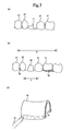
- Fig. 3 is an explanatory view showing Embodiment 3 of dental impression film according to this invention.
- the dental impression film in this embodiment is formed of an adhesive film 50 and looped projections 60.
- the adhesive film 50 having bonding capability with respect to a silicone impression material has, attached to the surface thereof to be bonded to an alginate impression material, numerous looped projections 60 which will become rigidly and inseparably entwined when permeated by and hardened with the alginate impression material.
- the surface of the adhesive film 50 to which the looped projections 60 are attached will be called the mounting surface, and the other surface of the adhesive film 50 the surface to be treated.
- the quality of the material employed to form the adhesive film 50 of the dental impression film has bonding capability with respect to the silicone impression material, and has a quality and thickness not easily separable when hardened.
- the alginate impression material 200 is applied to the mounting surface of the adhesive film 50, and the silicone impression material 100 to the surface to be treated of the adhesive film 50.
- the silicone impression material 100 when hardening, permeates the surface to be treated, and adheres to the adhesive film 50.
- the alginate impression material 200 when hardening, becomes entangled inseparably with the numerous looped projections 60 on the mounting surface.
- the alginate impression material 200 can be applied to the other surface of the dental impression film. Since the silicone impression material 100 and alginate impression material 200 can be hardened separately and independently, the silicone impression material 100 and alginate impression material 200 can be bonded at a time of forming an impression, which has been impossible heretofore, and which allows a precise impression to be taken at low cost using a small amount of silicone impression materials 100. As in Embodiment 1 and Embodiment 2, there is no need to match the timing of hardening of the silicone impression material 100 and alginate impression material 200. It becomes easy to carry out a series of operations from malaxation to completion of the impression.
- Fig. 4 is an explanatory view showing Embodiment 4 of dental impression film according to this invention.
- the dental impression film in this embodiment is formed of a silicone impression material film 70 and looped projections 80.
- the silicone impression material film 70 has, attached to the surface thereof to be bonded to an alginate impression material, numerous looped projections 80 which will become rigidly and inseparably entwined when permeated by and hardened with the alginate impression material.
- the surface of the silicone impression material film 70 to which the looped projections 60 are attached will be called the mounting surface, and the other surface of the silicone impression material film 70 the surface to be treated.
- the alginate impression material 200 is applied to the mounting surface of the silicone impression material film 70, and the silicone impression material 100 to the surface to be treated of the silicone impression material film 70.
- the silicone impression material 100 when hardened, rigidly joins the silicone impression material film 70, the alginate impression material 200, when hardened.
- the alginate impression material 200 when hardened, becomes entangled inseparably with the numerous looped projections 80 on the mounting surface.
- the silicone impression material 100 and alginate impression material 200 can be bonded, which has been impossible heretofore, and which allows a precise impression to be taken at low cost using a small amount of silicone impression materials 100.
- the alginate impression material 200 can be applied to the other surface of the dental impression film. Since the silicone impression material 100 and alginate impression material 200 can be hardned separately and independently, there is no need to match the timing of hardening of the silicone impression material 100 and alginate impression material 200 when forming an impression. It becomes easy to carry out a series of operations from malaxation to completion of the impression.
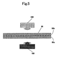
- Fig. 5 is an explanatory view showing Embodiment 5 of dental impression film according to this invention.
- the dental impression film in this embodiment is formed of an adhesive film 90 having bonding capability between silicone impression material and alginate impression material, respectively, and having a quality and thickness not easily separable when hardened.
- the silicone impression material 100 when hardened, adheres to a lower half region of the adhesive film 90
- the alginate impression material 200 when hardened, adheres to an upper half region of the adhesive film 90.
- the silicone impression material 100 and alginate impression material 200 can be hardened separately and independently, the silicone impression material 100 and alginate impression material 200 can be bonded at a time of forming an impression, which has been impossible heretofore, and which allows a precise impression to be taken at low cost using a small amount of silicone impression materials 100. As in Embodiment 1 and others, there is no need to match the timing of hardening of the silicone impression material 100 and alginate impression material 200. It becomes easy to carry out a series of operations from malaxation to completion of the impression.
- silicone impression materials such as addition type silicone and condensed type silicone.
- bonding with the dental impression film is based on the chemical property of material, only impression materials of the same type (added type or condensed type) can be bonded.
- the dental impression film not relying on chemical bonding (Embodiment 1, Embodiment 3 or Embodiment 5 described above), the impression material is not limited by bonding property.
- the method of manufacturing the dental impression film according to this invention is a method of manufacturing the dental impression film in which nonwoven resin fabrics are laid on opposite surfaces of a resin film, respectively, to form three layers, a virgin pulp is laid under the lowermost nonwoven resin fabric, then these are wound around a roll to form a rolled whole, and subsequently they are heated at a predetermined temperature with a heating device, thereby causing the nonwoven resin fabrics to thermally adhere to the opposite surfaces of the resin film.
- the method of manufacturing the dental impression film according to this invention is not limited to the following embodiments, but the specific contents of constituent elements can be varied as appropriate within a range corresponding to the purport of this invention.
- nonwoven resin fabrics are laid on opposite surfaces of a resin film, respectively, to form three layers.
- polyethylene film is employed as the resin film, and a double structure fiber of polyethylene/polyester as the nonwoven resin fabrics.
- the nonwoven resin fabrics are formed by mixing two types of yarn.
- the first yarn to mix has a fineness of 7.8dt, while the second yarn has a fineness of 3.3dt.
- As the dental impression film it is desirable to use a mixture of the first yarn in 70% - 50% and the second yarn in 30% - 50% as the material for the nonwoven resin fabrics.
- the dt indicating fineness stands for decitex.
- polyethylene film is, for example, the polyethylene film (brand name "Antibacterial One-Wrap (registered trademark) 220m", heatproof temperature of 110°C) manufactured by Nippon Paper-Pak Co., Ltd.
- the double structure fiber of polyethylene/polyester is, for example, a nonwoven fabric (part number "MF-1") manufactured by Shinwa Corp. This material has a feature that heat seal is easy, and its bonding strength is excellent.
- the width of the nonwoven resin fabric is set shorter than the width of the resin film. Then, when the two are overlapped, the nonwoven resin fabric is completely fitted inward of the resin film, thereby preventing poor bonding of impression materials.
- the surface of the nonwoven resin fabric can be protected, at the same time, impurities are prevented from adhering to the nonwoven resin fabric, and the nonwoven resin fabrics are prevented from adhering to each other.
- impurities are prevented from adhering to the nonwoven resin fabric, and the nonwoven resin fabrics are prevented from adhering to each other.
- uneven pressure is prevented from being applied between the resin film and the nonwoven resin fabrics. This allows the nonwoven resin fabrics to thermally adhere to the opposite surfaces of the resin film without breaking the three-dimensional fiber structure of the nonwoven fabrics.
- the width of the virgin pulp is set larger than the width of the resin film.
- the heating temperature by the heating device it is preferred to set it to or above the heatproof temperature of the resin film and within a range of 118 to 135°C. Specifically, it is appropriate to set the heating temperature to 118 to 121°C and carry out heating for about five minutes where the polyethylene film (brand name "Antibacterial One-Wrap (registered trademark) 220m", heatproof temperature of 110°C) manufactured by Nippon Paper-Pak Co., Ltd. is employed as polyethylene film, and the nonwoven fabric (part number "MF-1") manufactured by Shinwa Corp. is employed as the double structure fiber of polyethylene/polyester.
- the polyethylene film brand name "Antibacterial One-Wrap (registered trademark) 220m", heatproof temperature of 110°C
- the nonwoven fabric part number "MF-1" manufactured by Shinwa Corp.
- the heating device it is preferred to use a high-pressure steam sterilizer.
- This high-pressure steam sterilizer refers to an instrument that carries out saturated vapor sterilization under a pressure exceeding atmospheric pressure.
- This is an optimal heating device for manufacture of the dental impression film, which causes the nonwoven resin fabrics to thermally adhere to the opposite surfaces of the resin film by setting a predetermined sterilization temperature and sterilization time.
- the heating device is not limited to this.
- a handheld heater can be used. This type of heater has two arms which may be used to pinch the polyethylene film and polyethylene/polyester therebetween while being heated, thereby achieving thermal adhesion of the two materials.
- a stand When heating what is made in many winds and thickly into a roll form, adjustment may be made to set a long heating time and a somewhat high temperature, and a stand may be used to hold the roll in a floating state, since there is a possibility of causing thermo compression bonding due to its own weight acting on the lower end portion contacting the support surface of the heating device. Further, it is preferable to use a stand that can hold the roll in an upstanding state, in order to avoid an adhesion failure due to vapor becoming water drops in the film.
- Embodiment 6 A flow chart of an impression technique (two-step process) using the dental impression film according to this invention (hereinafter called registered trademark "miracle fit") will be described hereinafter as Embodiment 6.
- a method of using the dental impression films according to Embodiment 1 to Embodiment 5 this invention includes a step of preparing a wax tray and an impression step for taking impressions. Each of these steps will be described in the order of operations.
- the method of using the dental impression films will be described taking an example of forming a crown. This crown is, in this prosthesis production, attached to a position between teeth not to be treated.
- a wax tray is produced through the following substeps (1) - (3):
- the operation of pressing the paraffin wax (tray) in the oral cavity described in (3) may be carried out by warming and softening the paraffin wax in two plies with a dental gas torch or burner, which will cause little pain on the patient and simplify the production.
- a line is marked with a dental instrument or the like to indicate a tooth reference point. This tooth reference point is a mark used at a time of inserting the wax tray in the patient.
- the wax tray is cooled with tap water or the like, whereby the wax hardens to complete a firm wax tray. Since the temperature of the locality and the temperature of tap water are variable, chilled water may be used or hard type paraffin wax of high melting point may be used according to circumstances.
- the length of this wax tray will be described. Desirably, the length of the wax tray should cover a tray at a time of secondary impression described hereinafter.
- a wax tray for the teeth including the formation tooth and its required contact (contact point) is required. That is, the wax tray is required to have at least a size to protrude from the crown and cover part adjacent teeth adjoining the crown.
- impression of the patient's tooth is carried out. This step is executed through the following substeps (4) - (16). It is assumed for this example that, for the reason of one of the patient's teeth being eroded by decay as indicated by sign 11 in Fig. 7 (a) , the toothtop substance has been lost, and a crown is to be produced to replace the missing substance. Sign 21 in Fig. 7 (a) denotes teeth not to be treated.
- Bite taking can be carried out using the wax tray detached.
- Gypsum is poured into the silicone alginate impression material in accordance with a common method.
- the crown is produced based on the mold of gypsum obtained. Since accuracy near a silicone impression is taken, a temporary crown may be attached in order to prevent tooth movement until completion and attachment of a prosthesis, which will enable attachment of the prosthesis in a short time.
- Embodiment 7 relating to production of a plate denture will be described.
- a plate denture is different from what is called a crown (covering) like the crown in Embodiment 6, and is a set of false teeth or a partial denture with artificial gums.
- the dental impression film in Embodiment 1, Embodiment 3 or Embodiment 4 according to this invention can be used.
- Embodiment 7 assumes a patient who has had a plate denture produced.
- the construction of Embodiment 7 is effective where, even if a plate denture is once produced, a new plate denture needs to be produced after the gums become thin, for example. This embodiment is very significant in that a plate denture needs to be replaced with a new one in several years.
- the plate denture according to Embodiment 7 is produced by performing an adhesive liquid applying step S1, a film attaching step S2, an adhesive applying step S3, a silicone applying step S4, a mucosal surface impression step S5 and a tooth surface impression step S6. Details of these steps will be described in order.
- an adhesive liquid is applied to the dental impression film in Embodiment 1.
- the adhesive liquid is applied to one surface of the polyethylene polyester films 20 shown in Fig. 1 .
- the surface to which the adhesive liquid is applied becomes adhesive. This surface will be called the bonding surface.
- the dental impression film in Embodiment 1 has the opposite surfaces formed of the same material, the surface to which the adhesive liquid is applied is not limited to a particular surface.
- the adhesive liquid will be applied to the untreated surface of the adhesive film 50 when the dental impression film of Embodiment 3 is used, and to the untreated surface of the silicone impression material film 70 when the dental impression film of Embodiment 4 is used.
- a mucosa regulator to contact surfaces of the gums of the plate denture, as a measure of accommodating the shape of the inner surface of the original plate denture to the shape of the patient's gums to some extent.
- an acrylic adhesive is applied to contact portions 32 and their peripheries of the gums of the original plate denture 31.
- the meaning of applying this adhesive will be described hereinafter.
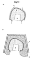
- the silicone 16 is coated thereon. In this way, the contact portions 32 of the gums in the form of a U-shaped recess is filled up with the silicone 16 as shown in Fig. 11 (b) .
- the patient After fitting the original plate denture 31 in the patient's oral cavity, the patient is asked to make tongue movement and jaw movement within the operate time of silicone 16. Once the retention time of silicone 16 starts, and before the silicone hardens, the patient is asked to keep still with the upper and lower jaws engaged. In this way, a dynamic impression (also called a functional impression) of the patient's gums can be taken, thereby providing a plate denture more suitable for use.
- a dynamic impression also called a functional impression
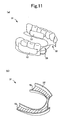
- Fig. 12 shows up to the step of putting the wax tray 15 on the remaining teeth 21.
- the wax tray 15 appears to have a cutout, this is provided for the purpose of illustrating the interior of wax tray 15. In practice, no such cutout exists.
- the length of this wax tray 15 is set to an extent of covering all the remaining teeth 21 pinched by the resin teeth reproduced on the plate denture 31.
- the wax tray 15 has a construction to protrude from the end of the remaining teeth 21 adjoining the plate denture.
- Fig. 13 shows up to the step of pressing on the patient's teeth the metal tray 19 filled with the alginate 26.
- the metal tray 19 appears to have a cutout exposing the alginate 26, this is provided for the purpose of illustrating the interior of metal tray 19. In practice, no such cutout exists.
- Embodiment 7 how a step corresponding to (16) in Embodiment 6 is executed will be described.
- the hardened alginate 26 placed in the metal tray 19 is taken out of the patient's oral cavity in a state of the original plate denture 31 buried therein.
- the hardened alginate 26 has, exposed on the impression surface thereof, the silicone 16 covering the surfaces of the contact portions 32 of the original plate denture 31, and the silicone 16 covering the surfaces of the miracle fits 13.
- a mold of the patient's gums is accurately transferred to the silicone 16 covering the surfaces of the contact portions 32, while a mold of the patient's remaining teeth 21 is accurately transferred to the silicone 16 covering the surfaces of the miracle fits 13.
- This preparation method can use an existing method using gypsum.
- the alginate 26 covers the entire jaw, portions of the plate denture not covered by the miracle fits 13, i.e. the occlusal portions of the plate denture, have also been transferred. Since the silicone 16 is not applied to such portions at all, when the metal tray 19 is pressed, the occlusal portions of the plate denture directly contact the alginate 26, and the occlusal portions of the plate denture are transferred onto the alginate 26. Such occlusal portions of the plate denture contacting the alginate 26 are necessary for reproducing an occlusion situation of false teeth. In order to inhibit wobbling in the oral cavity, the plate denture has a clasp 33 for fastening to a remaining tooth 21 [see Fig. 11 (a) ].
- the tooth to which the clasp 33 is fastened is called a hinge tooth. Since a mold of this hinge tooth is taken with the silicone 16, this clasp 33 can be produced precisely.
- the device for fastening the plate denture to the remaining tooth is not limited to this clasp 33.
- the construction of Embodiment 7 can be adapted to other devices than the clasp 33.
- the patient's gums and teeth can be transferred faithfully while saving on the expensive silicone 16. That is, the patient's plate denture is used in transferring the patient's gums. Since the shape of the plate denture is produced according to the patient, it is almost an imitation of the shape of the patient's gums.
- This plate denture may be regarded as a tray (support for the impression material), and the silicone 16 may be placed therein. Then, the amount of silicone 16 used can be reduced to a minimum.
- the miracle fits 13 are applied to the original plate denture. This allows the original plate denture to be collected. That is, the original plate denture is buried in the hardened alginate 26. However, the miracle fits 13 are arranged in positions between the original plate denture and hardened alginate 26. Therefore, the original plate denture and hardened alginate 26 do not adhere to each other. Since the miracle fits 13 can be stripped from the original plate denture simply, the original plate denture can be collected easily even after carrying out Embodiment 7.
- the dental impression film and the method of manufacturing the dental impression film according to this invention are suitable for the medical field.
Applications Claiming Priority (4)
| Application Number | Priority Date | Filing Date | Title |
|---|---|---|---|
| JP2007284405A JP4111250B1 (ja) | 2007-10-31 | 2007-10-31 | 歯科印象用フィルム及びそれを使用した印象採得方法 |
| JP2007311652A JP5108483B2 (ja) | 2007-11-30 | 2007-11-30 | 歯科印象用フィルムの製造方法 |
| PCT/JP2008/065053 WO2009057371A1 (fr) | 2007-10-31 | 2008-08-13 | Film pour impression dentaire et procédé de production de film pour impression dentaire |
| PCT/JP2008/069547 WO2009057591A1 (fr) | 2007-10-31 | 2008-10-28 | Film pour impression dentaire et procédé de production de film pour impression dentaire |
Publications (2)
| Publication Number | Publication Date |
|---|---|
| EP2113222A1 true EP2113222A1 (fr) | 2009-11-04 |
| EP2113222A4 EP2113222A4 (fr) | 2012-05-02 |
Family
ID=40590773
Family Applications (1)
| Application Number | Title | Priority Date | Filing Date |
|---|---|---|---|
| EP08845308A Withdrawn EP2113222A4 (fr) | 2007-10-31 | 2008-10-28 | Film pour impression dentaire et procédé de production de film pour impression dentaire |
Country Status (5)
| Country | Link |
|---|---|
| US (1) | US20100119988A1 (fr) |
| EP (1) | EP2113222A4 (fr) |
| AU (1) | AU2008319910B2 (fr) |
| CA (1) | CA2672305C (fr) |
| WO (2) | WO2009057371A1 (fr) |
Cited By (10)
| Publication number | Priority date | Publication date | Assignee | Title |
|---|---|---|---|---|
| WO2012016635A3 (fr) * | 2010-08-04 | 2012-04-19 | Charité - Universitätsmedizin Berlin | Procédé pour générer une topologie dentaire numérique pour une structure dentaire ainsi que procédé de mesure |
| US8851722B2 (en) | 2010-12-03 | 2014-10-07 | Docter Optics Se | Headlight lens for a vehicle headlight |
| US8899802B2 (en) | 2010-12-03 | 2014-12-02 | Docter Optics Se | Optical component for illumination purposes |
| US8905757B2 (en) | 2012-12-03 | 2014-12-09 | E. Kats Enterprises Ltd. | Method and apparatus for measuring a location and orientation of a plurality of implants |
| US8944649B2 (en) | 2010-12-03 | 2015-02-03 | Doctor Optics SE | Vehicle headlight |
| US9447939B2 (en) | 2012-05-15 | 2016-09-20 | Docter Optics Se | Headlight lens |
| US9599302B2 (en) | 2011-11-11 | 2017-03-21 | Docter Optics Se | Headlight lens for a vehicle headlight |
| US9719645B2 (en) | 2012-05-26 | 2017-08-01 | Docter Optics Se | Motor vehicle headlight having a complex headlight lens |
| US10018323B2 (en) | 2011-11-11 | 2018-07-10 | Docter Optics Se | Vehicle headlight |
| US10107466B2 (en) | 2010-12-03 | 2018-10-23 | Docter Optics Se | Headlight lens for a vehicle headlight |
Families Citing this family (4)
| Publication number | Priority date | Publication date | Assignee | Title |
|---|---|---|---|---|
| DK2720862T3 (en) | 2011-06-17 | 2016-09-19 | Fiberweb Inc | Vapor permeable, water impervious TOTAL MAJOR MULTI-LAYER ARTICLE |
| WO2012178027A2 (fr) | 2011-06-23 | 2012-12-27 | Fiberweb, Inc. | Article multicouches perméable à la vapeur d'eau, mais essentiellement imperméable à l'eau |
| DK2723568T3 (en) | 2011-06-23 | 2017-10-23 | Fiberweb Llc | Vapor permeable, essentially all water impermeable, multilayer |
| US9765459B2 (en) | 2011-06-24 | 2017-09-19 | Fiberweb, Llc | Vapor-permeable, substantially water-impermeable multilayer article |
Citations (3)
| Publication number | Priority date | Publication date | Assignee | Title |
|---|---|---|---|---|
| EP0557659A2 (fr) * | 1991-12-27 | 1993-09-01 | Mitsui Petrochemical Industries, Ltd. | Etoffe non-tissée stratifiée et procédé pour sa fabrication |
| US6042557A (en) * | 1998-06-10 | 2000-03-28 | K.R. Ferguson Technologies, Inc. | Orthopedic splints and methods of making same |
| EP1042994A1 (fr) * | 1998-09-24 | 2000-10-11 | Nissan Digital Process Ltd. | Element de prelevement des empreintes de la forme de dents et procede associe |
Family Cites Families (8)
| Publication number | Priority date | Publication date | Assignee | Title |
|---|---|---|---|---|
| JP2757048B2 (ja) * | 1989-11-13 | 1998-05-25 | 前田工繊株式会社 | 遮水シートの端末固定方法 |
| US5997989A (en) * | 1992-02-03 | 1999-12-07 | Bba Nonwovens Simpsonville, Inc. | Elastic nonwoven webs and method of making same |
| US5499917A (en) * | 1993-06-29 | 1996-03-19 | Minnesota Mining And Manufacturing Company | Dental isolation dam |
| US5616408A (en) * | 1995-12-22 | 1997-04-01 | Fiberweb North America, Inc. | Meltblown polyethylene fabrics and processes of making same |
| JPH1080434A (ja) * | 1996-09-10 | 1998-03-31 | Masahiro Tasaka | 歯科用印象用トレー |
| ATE504262T1 (de) * | 2002-07-17 | 2011-04-15 | Proxy Biomedical Ltd | Membrane für medizinische implantation |
| US8287275B2 (en) * | 2005-08-11 | 2012-10-16 | Eric Jon Knutson | Occlusal indicator tray and processes therefor |
| ITTO20070621A1 (it) * | 2007-09-03 | 2009-03-04 | Major Prod Dentari Spa | Prodotto composito per rilevare l'impronta di un'arcata edentula |
-
2008
- 2008-08-13 WO PCT/JP2008/065053 patent/WO2009057371A1/fr active Application Filing
- 2008-10-28 WO PCT/JP2008/069547 patent/WO2009057591A1/fr active Application Filing
- 2008-10-28 CA CA2672305A patent/CA2672305C/fr not_active Expired - Fee Related
- 2008-10-28 EP EP08845308A patent/EP2113222A4/fr not_active Withdrawn
- 2008-10-28 AU AU2008319910A patent/AU2008319910B2/en not_active Ceased
- 2008-10-28 US US12/530,197 patent/US20100119988A1/en not_active Abandoned
Patent Citations (3)
| Publication number | Priority date | Publication date | Assignee | Title |
|---|---|---|---|---|
| EP0557659A2 (fr) * | 1991-12-27 | 1993-09-01 | Mitsui Petrochemical Industries, Ltd. | Etoffe non-tissée stratifiée et procédé pour sa fabrication |
| US6042557A (en) * | 1998-06-10 | 2000-03-28 | K.R. Ferguson Technologies, Inc. | Orthopedic splints and methods of making same |
| EP1042994A1 (fr) * | 1998-09-24 | 2000-10-11 | Nissan Digital Process Ltd. | Element de prelevement des empreintes de la forme de dents et procede associe |
Non-Patent Citations (1)
| Title |
|---|
| See also references of WO2009057591A1 * |
Cited By (16)
| Publication number | Priority date | Publication date | Assignee | Title |
|---|---|---|---|---|
| WO2012016635A3 (fr) * | 2010-08-04 | 2012-04-19 | Charité - Universitätsmedizin Berlin | Procédé pour générer une topologie dentaire numérique pour une structure dentaire ainsi que procédé de mesure |
| US9458975B2 (en) | 2010-12-03 | 2016-10-04 | Docter Optics Se | Headlight lens for a vehicle headlight |
| US9599303B2 (en) | 2010-12-03 | 2017-03-21 | Docter Optics Se | Vehicle headlight |
| US10107466B2 (en) | 2010-12-03 | 2018-10-23 | Docter Optics Se | Headlight lens for a vehicle headlight |
| US8944649B2 (en) | 2010-12-03 | 2015-02-03 | Doctor Optics SE | Vehicle headlight |
| US9243769B2 (en) | 2010-12-03 | 2016-01-26 | Docter Optics Se | Motor vehicle |
| US9732925B2 (en) | 2010-12-03 | 2017-08-15 | Docter Optics Se | Headlight lens with two tunnel sections for separate light entry surfaces for a vehicle headlight |
| US8899802B2 (en) | 2010-12-03 | 2014-12-02 | Docter Optics Se | Optical component for illumination purposes |
| US8851722B2 (en) | 2010-12-03 | 2014-10-07 | Docter Optics Se | Headlight lens for a vehicle headlight |
| US9453628B2 (en) | 2010-12-03 | 2016-09-27 | Docter Optics Se | Headlight lens for a vehicle headlight |
| US9677732B2 (en) | 2010-12-03 | 2017-06-13 | Docter Optics Se | Headlight lens for a vehicle headlight |
| US9599302B2 (en) | 2011-11-11 | 2017-03-21 | Docter Optics Se | Headlight lens for a vehicle headlight |
| US10018323B2 (en) | 2011-11-11 | 2018-07-10 | Docter Optics Se | Vehicle headlight |
| US9447939B2 (en) | 2012-05-15 | 2016-09-20 | Docter Optics Se | Headlight lens |
| US9719645B2 (en) | 2012-05-26 | 2017-08-01 | Docter Optics Se | Motor vehicle headlight having a complex headlight lens |
| US8905757B2 (en) | 2012-12-03 | 2014-12-09 | E. Kats Enterprises Ltd. | Method and apparatus for measuring a location and orientation of a plurality of implants |
Also Published As
| Publication number | Publication date |
|---|---|
| US20100119988A1 (en) | 2010-05-13 |
| AU2008319910B2 (en) | 2010-06-24 |
| CA2672305A1 (fr) | 2009-05-07 |
| CA2672305C (fr) | 2010-07-06 |
| AU2008319910A1 (en) | 2009-05-07 |
| WO2009057371A1 (fr) | 2009-05-07 |
| EP2113222A4 (fr) | 2012-05-02 |
| WO2009057591A1 (fr) | 2009-05-07 |
Similar Documents
| Publication | Publication Date | Title |
|---|---|---|
| CA2672305C (fr) | Film pour impression dentaire et procede de production de film pour impression dentaire | |
| US6379147B1 (en) | Dental impression tray assembly with removable liner | |
| AU640588B2 (en) | Dental filling band | |
| US4504229A (en) | Dental placement devices and methods | |
| JPS5838544A (ja) | 歯科印象トレイの製作方法とそのブランク | |
| ATE444027T1 (de) | Verfahren zur herstellung einer zahnmedizinischen transfervorrichtung | |
| US20100203480A1 (en) | Dental crown shell and method of use | |
| US20140038130A1 (en) | System for Maintaining Tooth Contact During Interproximal Dental Restoration | |
| NO129831B (fr) | ||
| EP3146934B1 (fr) | Tampons pour boitiers orthodontiques et boitiers orthodontiques et procédés de fabrication de boitiers orthodontiques | |
| Orsborn | Bonded lingual retainers | |
| JP4500357B2 (ja) | 歯科印象用フィルム | |
| US20120100501A1 (en) | Preformed provisional crowns and methods for constructing temporary dental crowns and bridges | |
| JP6369858B2 (ja) | 咬合採得用義歯 | |
| WO1999060946A1 (fr) | Instrument dentaire | |
| US20030044748A1 (en) | Variable rigidity impression tray | |
| JPH1160425A (ja) | 繊維補強合成樹脂床義歯 | |
| JP2648856B2 (ja) | 有床義歯の作製方法 | |
| JP2010131181A (ja) | マウスガードの製造方法 | |
| EP2594223B1 (fr) | Fibre dentaire et procédé de fabrication d'une fibre dentaire | |
| CN220275745U (zh) | 一种前牙修复体的固定装置 | |
| JP5653463B2 (ja) | 歯の咬合再構成方法 | |
| Eade | A modified direct bond lingual retainer technique | |
| US810842A (en) | Artificial denture. | |
| JP4875944B2 (ja) | 義歯のチェックバイト法 |
Legal Events
| Date | Code | Title | Description |
|---|---|---|---|
| PUAI | Public reference made under article 153(3) epc to a published international application that has entered the european phase |
Free format text: ORIGINAL CODE: 0009012 |
|
| 17P | Request for examination filed |
Effective date: 20090620 |
|
| AK | Designated contracting states |
Kind code of ref document: A1 Designated state(s): AT BE BG CH CY CZ DE DK EE ES FI FR GB GR HR HU IE IS IT LI LT LU LV MC MT NL NO PL PT RO SE SI SK TR |
|
| DAX | Request for extension of the european patent (deleted) | ||
| A4 | Supplementary search report drawn up and despatched |
Effective date: 20120330 |
|
| RIC1 | Information provided on ipc code assigned before grant |
Ipc: A61C 9/00 20060101AFI20120326BHEP Ipc: A61K 6/10 20060101ALI20120326BHEP |
|
| 17Q | First examination report despatched |
Effective date: 20141218 |
|
| STAA | Information on the status of an ep patent application or granted ep patent |
Free format text: STATUS: THE APPLICATION IS DEEMED TO BE WITHDRAWN |
|
| 18D | Application deemed to be withdrawn |
Effective date: 20160112 |